

Page 1
G60
ENABLING BRIGHT OUTCOMES
User Guide
Page 2

Barco NV
Beneluxpark 21, 8500 Kortrijk, Belgium
www.barco.com/en/support
www.barco.com
Registered office: Barco NV
President Kennedypark 35, 8500 Kortrijk, Belgium
www.barco.com/en/support
www.barco.com
Page 3

Copyright ©
All rights reserved. No part of this document may be copied, reproduced or translated. It shall not otherwise be
recorded, transmitted or stored in a retrieval system without the prior written consent of Barco.
Changes
Barco provides this manual 'as is' without warranty of any kind, either expressed or implied, including but not
limited to the implied warranties or merchantability and fitness for a particular purpose. Barco may make
improvements and/or changes to the product(s) and/or the program(s) described in this publication at any time
without notice.
This publication could contain technical inaccuracies or typographical errors. Changes are periodically made
to the information in this publication; these changes are incorporated in new editions of this publication.
The latest edition of Barco manuals can be downloaded from the Barco web site www.barco.com or from the
secured Barco web site https://www.barco.com/en/signin.
Trademarks
Brand and product names mentioned in this manual may be trademarks, registered trademarks or copyrights
of their respective holders. All brand and product names mentioned in this manual serve as comments or
examples and are not to be understood as advertising for the products or their manufacturers.
Trademarks
• Crestron is a registered trademark of Crestron Electronics, Inc. of the United States.
• Extron is a registered trademark of Extron Electronics, Inc. of the United States.
• AMX is a registered trademark of AMX LLC of the United States.
• PJLink applied for trademark and logo registration in Japan, the United States of America, and other
countries by JBMIA.
Guarantee and Compensation
Barco provides a guarantee relating to perfect manufacturing as part of the legally stipulated terms of
guarantee. On receipt, the purchaser must immediately inspect all delivered goods for damage incurred during
transport, as well as for material and manufacturing faults Barco must be informed immediately in writing of
any complaints.
The period of guarantee begins on the date of transfer of risks, in the case of special systems and software on
the date of commissioning, at latest 30 days after the transfer of risks. In the event of justified notice of
complaint, Barco can repair the fault or provide a replacement at its own discretion within an appropriate
period. If this measure proves to be impossible or unsuccessful, the purchaser can demand a reduction in the
purchase price or cancellation of the contract. All other claims, in particular those relating to compensation for
direct or indirect damage, and also damage attributed to the operation of software as well as to other services
provided by Barco, being a component of the system or independent service, will be deemed invalid provided
the damage is not proven to be attributed to the absence of properties guaranteed in writing or due to the
intent or gross negligence or part of Barco.
If the purchaser or a third party carries out modifications or repairs on goods delivered by Barco, or if the
goods are handled incorrectly, in particular if the systems are operated incorrectly or if, after the transfer of
risks, the goods are subject to influences not agreed upon in the contract, all guarantee claims of the
purchaser will be rendered invalid. Not included in the guarantee coverage are system failures which are
attributed to programs or special electronic circuitry provided by the purchaser, e.g. interfaces. Normal wear
as well as normal maintenance are not subject to the guarantee provided by Barco either.
The environmental conditions as well as the servicing and maintenance regulations specified in this manual
must be complied with by the customer.
Federal Communications Commission (FCC Statement)
This equipment has been tested and found to comply with the limits for a class A digital device, pursuant to
Part 15 of the FCC rules. These limits are designed to provide reasonable protection against harmful
interference when the equipment is operated in a commercial environment. This equipment generates, uses,
and can radiate radio frequency energy and, if not installed and used in accordance with the instruction
manual, may cause harmful interference to radio communications. Operation of this equipment in a residential
Page 4

area may cause harmful interference, in which case the user will be responsible for correcting any interference
at his own expense
Changes or modifications not expressly approved by the party responsible for compliance could void the
user's authority to operate the equipment
FCC responsible: Barco Inc.
3059 Premiere Parkway Suite 400
30097 Duluth GA, United States
Tel: +1 678 475 8000
Patent protection
Please refer to www.barco.com/about-barco/legal/patents
EMC notices
EN55032/CISPR32 Class A MME (MultiMedia Equipment)
Warning : This equipment is compliant with Class A of CISPR 32. In a residential environment this equipment
may cause radio interference.
GB/T 9254 Class A ITE (Information Technology Equipment)
Warning : This is a class A product. In a domestic environment this product may cause radio interference in
which case the user may be required to take adequate measures.
BSMI Taiwan Class A statement:
警告使用者 : 此為甲類資訊技術設備,於居住環境中使用 ,可能會造成射頻擾動,在此情況下,使用者會被要
求採取某些適當的對策。
Page 5

Table of contents
1 Safety.........................................................................................................................................................................................................................7
1.1 General considerations ....................................................................................................................................................................8
1.2 Important safety instructions ......................................................................................................................................................10
1.3 Product safety labels.......................................................................................................................................................................13
1.4 Risk Group 3 Safety ........................................................................................................................................................................14
1.4.1 General considerations ..............................................................................................................................................14
1.4.2 High Brightness precautions: Hazard Distance ............................................................................................ 15
1.4.3 HD for fully enclosed projection systems ......................................................................................................... 17
2 Product overview ...........................................................................................................................................................................................19
2.1 Main unit.................................................................................................................................................................................................20
2.2 Input/Output (I/O) Panel ................................................................................................................................................................21
2.3 Control panel .......................................................................................................................................................................................22
2.4 Remote Control Unit (RCU) ........................................................................................................................................................23
3 Powering On/Off the projector..............................................................................................................................................................25
3.1 Powering On the projector...........................................................................................................................................................26
3.2 Powering Off the Projector...........................................................................................................................................................26
4 User controls.....................................................................................................................................................................................................29
4.1 On-Screen Display Menus...........................................................................................................................................................30
4.2 Picture Menu .......................................................................................................................................................................................31
4.3 Screen Menu .......................................................................................................................................................................................34
4.4 Settings Menu.....................................................................................................................................................................................38
4.5 Light Source Menu ...........................................................................................................................................................................39
4.6 Options Menu......................................................................................................................................................................................40
4.7 3D Menu.................................................................................................................................................................................................42
4.8 Communications Menu..................................................................................................................................................................43
4.9 Controlling the projector over network ..................................................................................................................................44
4.10 Using the web control center......................................................................................................................................................45
4.11 Using RS232 command by Telnet ...........................................................................................................................................47
5 Troubleshooting..............................................................................................................................................................................................49
5.1 LED indication chart ........................................................................................................................................................................50
5.2 Projector Problems .......................................................................................................................................................................... 51
A Specifications...................................................................................................................................................................................................53
A.1 Product specification of the G60-W7 .....................................................................................................................................54
A.2 Product specification of the G60-W8 .....................................................................................................................................55
A.3 Product specification of the G60-W10 ..................................................................................................................................56
A.4 Compatibility modes........................................................................................................................................................................57
R5910888 /05 G60
5
Page 6

A.5 Dimensions of the G60 ..................................................................................................................................................................61
A.6 Ceiling mount ......................................................................................................................................................................................62
B Environmental information .....................................................................................................................................................................65
B.1 China RoHS compliance...............................................................................................................................................................66
B.2 Taiwan RoHS compliance ............................................................................................................................................................ 67
B.3 Turkey RoHS compliance ............................................................................................................................................................68
B.4 Disposal information........................................................................................................................................................................68
B.5 Production address..........................................................................................................................................................................69
B.6 Contact information .........................................................................................................................................................................69
B.7 Download Product Manual ..........................................................................................................................................................69
Glossary.................................................................................................................................................................................................................71
Index.........................................................................................................................................................................................................................73
R5910888 /05 G606
Page 7
Safety 1
About this document
Read this document attentively. It contains important information to prevent personal injury while installing and
using the G60 projector. Furthermore, it includes several cautions to prevent damage to the G60 projector.
Ensure that you understand and follow all safety guidelines, safety instructions and warnings mentioned in this
chapter before installing the G60 projector.
Clarification of the term “G60” used in this document
When referring in this document to the term “G60” means that the content is applicable for following Barco
products:
• G60-W7, G60-W8, G60-W10
Model certification name
• G60
Barco provides a guarantee relating to perfect manufacturing as part of the legally stipulated terms
of guarantee. Observing the specification mentioned in this chapter is critical for projector
performance. Neglecting this can result in loss of warranty.
Overview
•
General considerations
• Important safety instructions
• Product safety labels
• Risk Group 3 Safety
R5910888 /05 G60
7
Page 8

Safety
1.1 General considerations
General safety instructions
• Before operating this equipment please read this manual thoroughly and retain it for future reference.
• Installation and preliminary adjustments should be performed by qualified Barco personnel or by
authorized Barco service dealers.
• All warnings on the projector and in the documentation manuals should be adhered to.
• All instructions for operating and use of this equipment must be followed precisely.
• All local installation codes should be adhered to.
• IEC 60825-1: 2014 Class 1 RG2
• IEC 62471-5:2015 RG2
• Additional instructions to supervise children, no staring, and not use optical aids.
• Additional instructions to install above the reach of children.
• Notice is given to supervise children and to never allow them to stare into the projector beam at any
distance from the projector.
• Notice is given to use caution when using the remote control for starting the projector while in front of the
projection lens.
• Notice is given to the user to avoid the use of optical aids such as binoculars or telescopes inside the
beam.
• “As with any bright light source, do not stare into the beam, RG2 IEC 62471-5:2015”.
• “WARNING: MOUNT ABOVE THE HEADS OF CHILDREN. The use of a ceiling mount is recommended
with this product to place it above the eyes of children.
Notice on safety
This equipment is built in accordance with the requirements of the international safety standards IEC60950-1,
EN60950-1, UL60950-1 and CAN/CSA C22.2 No.60950-1, which are the safety standards of information
technology equipment including electrical business equipment. These safety standards impose important
requirements on the use of safety critical components, materials and insulation, in order to protect the user or
operator against risk of electric shock and energy hazard and having access to live parts. Safety standards
also impose limits to the internal and external temperature rises, radiation levels, mechanical stability and
strength, enclosure construction and protection against the risk of fire. Simulated single fault condition testing
ensures the safety of the equipment to the user even when the equipment's normal operation fails.
Laser safety precautions for G60-W7 series
This product is classified as Class 1 Laser Product-Risk Group 2 of IEC 60825-1 : 2014 and Class 3R Laser
product of IEC 60825-1:2007, complying with 21 CFR 1040.10 and 1040.11 except for deviations pursuant to
Laser Notice No.50, dated June 24, 2007.
To ensure safety operation, read all laser safety precautions before installing and operating the projector.
• Class 3R Laser product. Do NOT deliberately look into or stare into the beam, which can cause injury to
the retina in the back of the eye.
• This projector uses extremely high brightness laser. Never attempt to look directly into the lens or into the
light beam. The bright light may result in permanent eye damage. (Risk Group 2 of IEC 62471-5:2015).
• When turning on the projector, make sure no one within projection range is looking into the lens.
• Keep any reflective objects out of the light path of the projector. Glass and shiny surfaces can reflect the
light beam from the lens as the light path is extensive, and the reflective beam can cause unpredictable
incident such as fire hazards or eye injuries.
• Any operation or adjustment not specifically instructed by the user’s guide creates the risk of hazardous
laser radiation exposure.
• Do not open or disassemble the projector as this may cause damage by the exposure of laser radiation.
• Failure to follow the control, adjustment or operation procedures may cause damage by the exposure of
laser radiation.
Laser safety precautions for G60-W8 series
This product is classified as CLASS 1 LASER PRODUCT - RISK GROUP 2 of IEC 60825-1 : 2014 and also
complies with 21 CFR 1040.10 and 1040.11 except for conformance as a Risk Group 2 LIP as defined in IEC
62471-5:Ed. 1.0. For more information see Laser Notice No. 57, dated May 8, 2019.
R5910888 /05 G608
Page 9

Safety
According to IEC 60825-1:2014 and IEC 62471-5:2015, this projector may be CLASS 1 LASER PRODUCT RISK GROUP 2 product.
To ensure safety operation, read all laser safety precautions before installing and operating the projector.
• This projector uses extremely high brightness laser. Never attempt to look directly into the lens or into the
light beam. The bright light may result in permanent eye damage. (Risk Group 2 of IEC 62471-5:2015).
• No direct exposure to the beam shall be permitted.
• Possibly hazardous optical radiation emitted from this product.
• This projector has a built-in Class 4 laser module. Never attempt to disassemble or modify the laser
module.
• Any operation or adjustment not specifically instructed in the User manual creates the risk of hazardous
laser radiation exposure.
• Do not stare into beam when the projector is on. When turning on the projector, make sure no one within
projection range is looking into the lens.
• Follow the control, adjustment, or operation procedures to avoid damage or injury from exposure of laser
radiation.
• The instructions for the assembly, operation, and maintenance include clear warnings concerning
precautions to avoid possible exposure to hazardous laser radiation.
Laser safety precautions for G60-W10 series
This product is classified as Class 1 Laser Product-Risk Group 2 (RG2 ) of IEC 60825-1: 2014 and Class 3R
Laser product of IEC 60825-1:2007, complying with 21 CFR 1040.10 and 1040.11 except for deviations
pursuant to Laser Notice No.50, dated June 24, 2007.
When installed with G LENS (2.90 - 5.50 : 1) lens (throw ratio 2.90-5.50), this projector may become Class 1
Laser Product-Risk Group 3 (RG3) according to IEC 60825-1:2014, IEC 62471-5: 2015, and also make a
variance approvals under 21 CFR 1010.4 for RG3 LIP according to Classification and Requirements for Laser
Illuminated Projectors (LIPs) (Laser Notice No. 57).
To ensure safety operation, read all laser safety precautions before installing and operating the projector.
• This projector uses extremely high brightness laser. Do not stare into the direct light beam, as the
extremely high brightness may cause permanent eye damage. (Risk Group 2 of IEC 62471-5:2015).
• No direct exposure to the beam shall be permitted. (Risk Group 3 of IEC 62471-5:2015).
• This product is not for household use.
• Possibly hazardous optical radiation emitted from this product.
• This projector has a built-in Class 4 laser module. Never attempt to disassemble or modify the laser
module.
• Any operation or adjustment not specifically instructed in the User manual creates the risk of hazardous
laser radiation exposure.
• Do not stare into beam when the projector is on. When turning on the projector, make sure no one within
projection range is looking into the lens.
• Follow the control, adjustment, or operation procedures to avoid damage or injury from exposure of laser
radiation.
• The instructions for the assembly, operation, and maintenance include clear warnings concerning
precautions to avoid possible exposure to hazardous laser radiation.
Light Intensity Hazard Distance for G60-W10 series
This projector may become Class 1 Laser Product-Risk Group 3 (RG3) when installed with G LENS (2.90 -
5.50 : 1) lens (throw ratio 2.90-5.50). Permanent eye injury is possible when exposed to the high intensity light
beam within the hazard distance (HD).
Projection Lens
G LENS (2.90 - 5.50 : 1) 2.90-5.50 World wide except US
Throw Ratio
Classification and Requirements for Laser
Illuminated Projectors (LIPs)
World wide include US
(IEC 60825-1:2014)
CLASS 1 RISK GROUP 3
(IEC 62471-5: 2015)
HD: 3.0 meters
R5910888 /05 G60 9
Page 10

Safety
Follow the precautions to avoid light intensity hazard.
• NEVER look into the lens! High intensity light beam.
• Permanent eye injury is possible when exposed to the high intensity light beam within the hazard distance.
• Operators shall control access to the light beam within the hazard distance or install the product at a height
that will prevent eye exposure within the hazard distance.
• Do not place any reflective objects in the light path of the projector.
User definition
Throughout this manual, the term SERVICE PERSONNEL refers to Barco authorized persons having
appropriate technical training and experience necessary to be knowledgeable of potential hazards to which
they are exposed (including, but not limited to HIGH VOLTAGE ELECTRIC and ELECTRONIC CIRCUITRY
and HIGH BRIGHTNESS PROJECTORS) in performing a task, and of measures to minimize the potential risk
to themselves or other persons. Only Barco authorized SERVICE PERSONNEL, knowledgeable of such risks,
are allowed to perform service functions inside the product enclosure. The term USER and OPERATOR refers
to any person other than SERVICE PERSONNEL. When installing an interchangeable lens with a throw ratio
that make the projector become RG3, refer to chapter “Risk Group 3 Safety”, page 9. Such combination of
projector and lens are intended for professional use only, and are not intended for consumer use.
FOR PROFESSIONAL USE ONLY means installation can only be carried out by Barco AUTHORIZED
PERSONNEL familiar with potential hazards associated with high intensity light beams.
1.2 Important safety instructions
To prevent the risk of electrical shock
• This product should be operated from a mono phase AC power source.
• This apparatus must be grounded (earthed) via the supplied 3 conductor AC power cable. If none of the
supplied power cables are the correct one, consult your dealer. If you are unable to insert the plug into the
outlet, contact your electrician to replace your obsolete outlet. Do not defeat the purpose of the groundingtype plug.
• Do not allow anything to rest on the power cord. Do not locate this product where persons will walk on the
cord. To disconnect the cord, pull it out by the plug. Never pull the cord itself.
• Use only the power cord supplied with your device. While appearing to be similar, other power cords have
not been safety tested at the factory and may not be used to power the device. For a replacement power
cord, contact your dealer.
• Do not operate the projector with a damaged cord. Replace the cord.
• Do not operate the projector if the projector has been dropped or damaged until it has been examined and
approved for operation by a qualified service technician. Position the cord so that it will not be tripped over,
pulled, or contact hot surfaces.
• If an extension cord is necessary, a cord with a current rating at least equal to that of the projector should
be used. A cord rated for less amperage than the projector may overheat.
• Never push objects of any kind into this product through cabinet slots as they may touch dangerous
voltage points or short out parts that could result in a risk of fire or electrical shock.
• Do not expose this projector to rain or moisture.
• Do not immerse or expose this projector in water or other liquids.
• Do not spill liquid of any kind on this projector.
• Should any liquid or solid object fall into the cabinet, unplug the set and have it checked by qualified
service personnel before resuming operations.
• Do not disassemble this projector, always take it to an authorized trained service person when service or
repair work is required.
• Do not use an accessory attachment which is not recommended by the manufacturer.
• Lightning - For added protection for this video product during a lightning storm, or when it is left unattended
and unused for long periods of time, unplug it from the wall outlet. This will prevent damage to the device
due to lightning and AC power-line surges.
To prevent personal injury
• To prevent injury and physical damage, always read this manual and all labels on the system before
connecting to the wall outlet or adjusting the projector.
R5910888 /05 G6010
Page 11

Safety
• To prevent injury, take note of the weight of the projector.
• To prevent injury, ensure that the lens and all covers are correctly installed. See installation procedures.
• Warning: high intensity light beam. NEVER look into the lens ! High luminance could result in damage to
the eye.
• Warning: extremely high brightness laser: This projector uses extremely high brightness laser. Never
attempt to look directly into the lens or at the laser.
• Before attempting to remove any of the projector’s covers, you must turn off the projector and disconnect
from the wall outlet.
• When required to switch off the projector, to access parts inside, always disconnect the power cord from
the power net.
• The power input at the projector side is considered as the disconnect device. When required to switch off
the projector, to access parts inside, always disconnect the power cord at the projector side. In case the
power input at the projector side is not accessible (e.g. ceiling mount), the socket outlet supplying the
projector shall be installed nearby the projector and be easily accessible, or a readily accessible general
disconnect device shall be incorporated in the fixed wiring.
• Do not place this equipment on an unstable cart, stand, or table. The product may fall, causing serious
damage to it and possible injury to the user.
• It is hazardous to operate without lens or shield. Lenses, shields or ultra violet screens shall be changed if
they have become visibly damaged to such an extent that their effectiveness is impaired. For example by
cracks or deep scratches.
• Exposure to UV radiation: Some medications are known to make individuals extra sensitive to UV
radiation. The American Conference of Governmental Industrial Hygienists (ACGIH) recommends
occupational UV exposure for an-8 hour day to be less than 0,1 micro-watts per square centimeters of
effective UV radiation. An evaluation of the workplace is advised to assure employees are not exposed to
cumulative radiation levels exceeding these government guidelines. The exposer of this UV radiation is
allowed for only 1 hour per day for maintenance and service persons.
To prevent fire hazard
• Do not place flammable or combustible materials near the projector!
• Barco large screen projection products are designed and manufactured to meet the most stringent safety
regulations. This projector radiates heat on its external surfaces and from ventilation ducts during normal
operation, which is both normal and safe. Exposing flammable or combustible materials into close
proximity of this projector could result in the spontaneous ignition of that material, resulting in a fire. For this
reason, it is absolutely necessary to leave an “exclusion zone” around all external surfaces of the projector
whereby no flammable or combustible materials are present. The exclusion zone must be not less than
100 cm (39.4”) for all DLP projectors. The exclusion zone on the lens side must be at least 5 m. Do not
cover the projector or the lens with any material while the projector is in operation. Keep flammable and
combustible materials away from the projector at all times. Mount the projector in a well-ventilated area
away from sources of ignition and out of direct sun light. Never expose the projector to rain or moisture. In
the event of fire, use sand, CO2 or dry powder fire extinguishers. Never use water on an electrical fire.
Always have service performed on this projector by authorized Barco service personnel. Always insist on
genuine Barco replacement parts. Never use non- Barco replacement parts as they may degrade the
safety of this projector.
• Slots and openings in this equipment are provided for ventilation. To ensure reliable operation of the
projector and to protect it from overheating, these openings must not be blocked or covered. The openings
should never be blocked by placing the projector too close to walls, or other similar surface. This projector
should never be placed near or over a radiator or heat register. This projector should not be placed in a
built-in installation or enclosure unless proper ventilation is provided.
• Projection rooms must be well ventilated or cooled in order to avoid build up of heat.
• Let the projector cool down completely before storing. Remove cord from the projector when storing.
To prevent projector damage
• Always remove lens cap before switching on the projector. If the lens cap is not removed, it may melt due
to the high energy light emitted through the lens. Melting the lens cap may permanently damage the
surface of the projection lens.
• The air filters of the projector must be cleaned or replaced on a regular basis. Cleaning the booth area
would be monthly minimum. Neglecting this could result in disrupting the air flow inside the projector,
causing overheating. Overheating may lead to the projector shutting down during operation.
• The projector must always be installed in a manner which ensures free flow of air into its air inlets and
unimpeded evacuation of the hot air from its cooling system.
R5910888 /05 G60 11
Page 12
100 cm
(39.4”)
100 cm
(39.4”)
100 cm
(39.4”)
100 cm
(39.4”)
30 mm
(1.2”)
10.1 mm
(0.4”)
1 2
Safety
• If more than one projector is installed in a common projection booth, the exhaust air flow requirements are
valid for EACH individual projector system. Note that inadequate air extraction or cooling will result in
decreased life expectancy of the projector as a whole as well as causing premature failure of the lasers.
• In order to ensure that correct airflow is maintained, and that the projector complies with Electromagnetic
Compatibility (EMC) requirements, it should always be operated with all of its covers in place.
• Slots and openings in the cabinet are provided for ventilation. To ensure reliable operation of the product
and to protect it from overheating, these openings must not be blocked or covered. The openings should
never be blocked by placing the product on a bed, sofa, rug, or other similar surface. This product should
never be placed near or over a radiator or heat register. The device should not be placed in a built-in
installation or enclosure unless proper ventilation is provided.
• Ensure that nothing can be spilled on, or dropped inside the projector. If this does happen, switch off and
unplug the mains supply immediately. Do not operate the projector again until it has been checked by
qualified service personnel.
• Do not block the projector cooling fans or free air movement around the projector.
• Do not use this equipment near water.
• Special care for Laser Beams: Special care should be used when DLP projectors are used in the same
room as high power laser equipment. Direct or indirect hitting of a laser beam on to the lens can severely
damage the Digital Mirror Devices™ in which case there is a loss of warranty.
• Never place the projector in direct sun light. Sun light on the lens can severely damage the Digital Mirror
Devices™ in which case there is a loss of warranty.
• Save the original shipping carton and packing material. They will come in handy if you ever have to ship
your equipment. For maximum protection, repack your set as it was originally packed at the factory.
• Unplug this product from the wall outlet before cleaning. Do not use liquid cleaners or aerosol cleaners.
Use a damp cloth for cleaning. Never use strong solvents, such as thinner or benzine, or abrasive
cleaners, since these will damage the cabinet. Stubborn stains may be removed with a cloth lightly
dampened with mild detergent solution.
• To ensure the highest optical performance and resolution, the projection lenses are specially treated with
an anti-reflective coating, therefore, avoid touching the lens. To remove dust on the lens, use a soft dry
cloth. Do not use a damp cloth, detergent solution, or thinner.
• Rated operating ambient temperature: ta= 5 °C (41 °F) to 40 °C (104 °F).
• Rated operating humidity: 10% RH to 85% RH (non-condensing). This projector can be set to any angle
within 360° range.
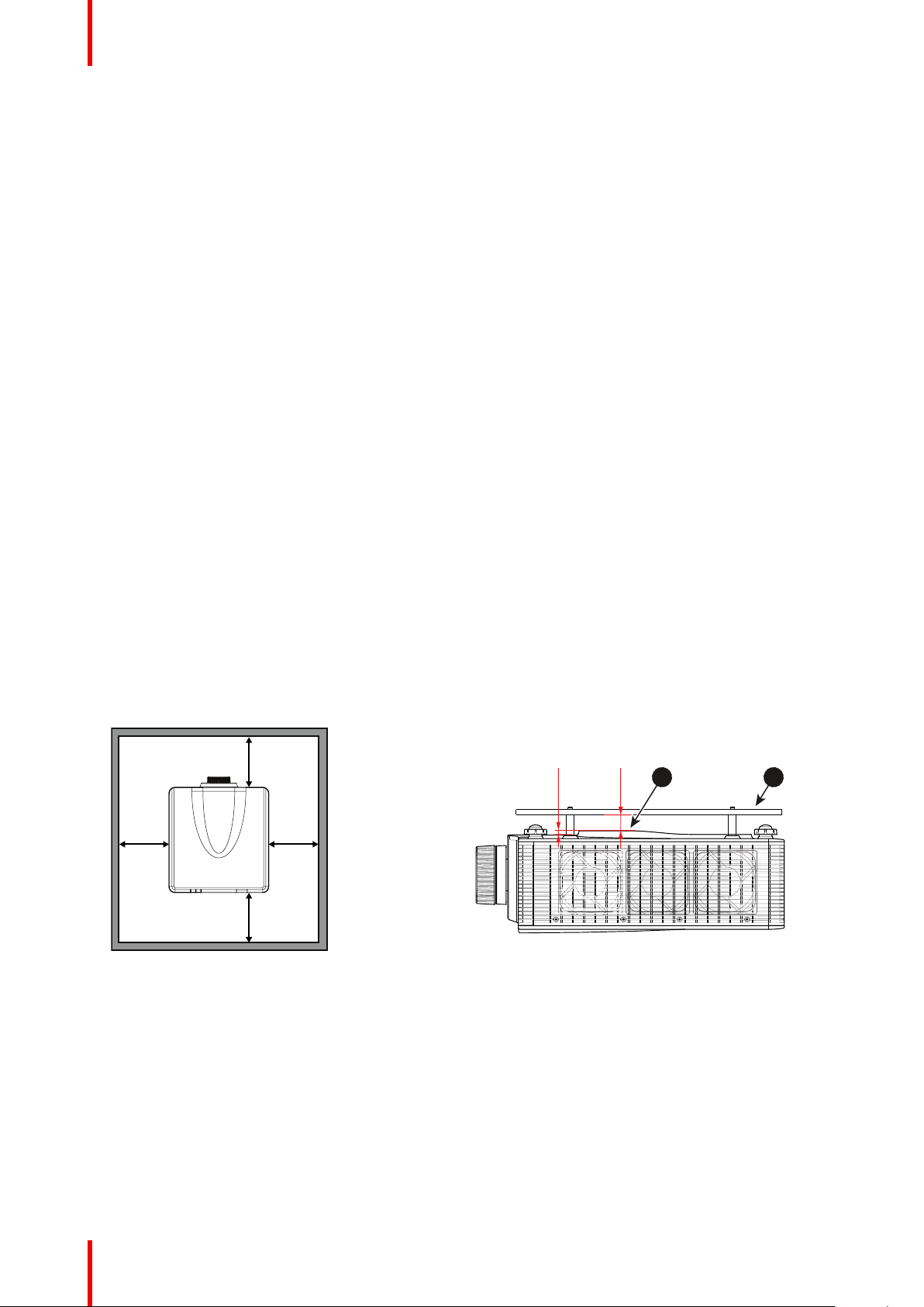
• Allowing proper space around the projector is critical for proper air circulation and cooling of the unit. The
dimensions shown here indicate the minimum space required.
Image 1-1
1 Bottom intake vents.
2 Ceiling mount plate.
• For ceiling mounted installations, make sure to leave 30 mm (1.2”) between the ceiling mount and the
bottom intake vents of the projector.
To prevent battery explosion
• Danger of explosion if battery is incorrectly installed.
• Replace only with the same or equivalent type recommended by the manufacturer.
• For disposal of used batteries, always consult federal, state, local and provincial hazardous waste disposal
rules and regulations to ensure proper disposal.
R5910888 /05 G6012
Page 13
RG 2
COMPLIES WITH
21 CFR 1040.10AND
1040.11 E
XCEPT FOR
DEVIATIONS PURSUANT
TO LASER NOTICE No. 50,
DATED JUNE 24, 2007.
IEC/EN 60825-1:2007
IEC/EN 60825-1 : 2007
LASER RADIATION -AVOID DIRECT EYE EXPOSURE - CLASS 3R LASER PRODUCT
Wave length : 449-461 nm / Max. Pulse energy : 0.52mJ / Pulse duration : 1.06 ms
IEC/EN 60825-1 : 2014 CLASS 1 LASER PRODUCT/ RISK GROUP 2
WARNING : Possibly hazardous optical radiation emitted from this product.
Do not stare into the beam, May be harmful to the eyes.
IEC/EN 60825-1 : 2007
IEC/EN 60825-1 : 2014
IEC/EN 60825-1 : 2007
RAYONNEMENTLASER - ÉVITEZ TOUTE EXPOSITION DIRECTE DES YEUX PRODUITLASER DE CLASSE 3R
Longueur d'ondes : 449 - 461 nm / Max.impulsion d'énergie : 0.52 mJ /
Durée impulsions 1.06 ms
IEC/EN 60825-1 : 2014 PRODUITLASER DE CLASSE 1 / GROUPE A RISQUE 2
AVERTISSEMENT: Risquse possibles de rayonnements optiques émis par ce produit.
Ne pas regarder dans le faisceau. Peut être dangereux pour les yeux.
IEC/EN 60825-1 : 2007
IEC/EN 60825-1 : 2014
Safety
On servicing
• Do not attempt to service this product yourself, as opening or removing covers may expose you to
dangerous voltage potentials and risk of electric shock.
• Refer all servicing to qualified service personnel.
• Attempts to alter the factory-set internal controls or to change other control settings not specially discussed
in this manual can lead to permanent damage to the projector and cancellation of the warranty.
• Remove all power from the projector and refer servicing to qualified service technicians under the following
conditions:
- When the power cord or plug is damaged or frayed.
- If liquid has been spilled into the equipment.
- If the product has been exposed to rain or water.
- If the product does not operate normally when the operating instructions are followed. Adjust only those
controls that are covered by the operating instructions since improper adjustment of the other controls
may result in damage and will often require extensive work by a qualified technician to restore the
product to normal operation.
- If the product has been dropped or the cabinet has been damaged.
- If the product exhibits a distinct change in performance, indicating a need for service.
• Replacement parts: When replacement parts are required, be sure the service technician has used original
Barco replacement parts or authorized replacement parts which have the same characteristics as the
Barco original part. Unauthorized substitutions may result in degraded performance and reliability, fire,
electric shock or other hazards. Unauthorized substitutions may void warranty.
• Safety check: Upon completion of any service or repairs to this projector, ask the service technician to
perform safety checks to determine that the product is in proper operating condition.
Safety Data Sheets for Hazardous Chemicals
For safe handling information on chemical products, consult the Safety Data Sheet (SDS). SDSs are available
upon request via safetydatasheets@barco.com.
1.3 Product safety labels
Light beam related safety labels for G60-W7 series
Label image Label description
Risk Group 2 of IEC60825-1:2014 and Class 3R Laser product of
IEC 60825-1:2007. Do not look into the laser light. The extremely
high brightness may cause permanent eye damage.
This product is classified as Class 1 Laser Product-Risk Group 2 of
IEC 60825-1 : 2014 and Class 3R Laser product of IEC 608251:2007, complying with 21 CFR 1040.10 and 1040.11 except for
deviations pursuant to Laser Notice No.50, dated June 24, 2007.
R5910888 /05 G60 13
Page 14

Thi s produ ct comp lies wi th perf orman ce stan dards f or lase r
pro ducts u nder 21 C FR Part 1 040 exc ept wit h respe ct to tho se
cha racte risti cs auth orize d by Varia nce Num ber XXX X-X-X XXX
effe ctive [ inser t the da te of the v arian ce appr oval]
BAR CO INC
305 9 Premi ere Par kway Su ite 400 , Dulut h, GA 3009 7, USA
U.S .A. Onl y
Safety
Light beam related safety labels for G60-W8 series
Label image Label description
Risk Group 2, IEC60825-1:2014. Do not look into the laser light. The
extremely high brightness may cause permanent eye damage.
This product is classified as Class 1 Laser Product-Risk Group 2 of
IEC 60825-1:2014 and also complies with 21 CFR 1040.10 and
1040.11 as a Risk Group 2, LIP ( Laser Illuminated Projector) as
defined in IEC 62471-5:Ed.1.0. For more information see Laser
Notice No. 507, dated May 8, 2019.
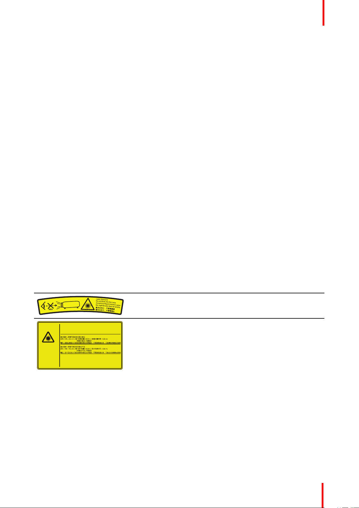
Light beam related safety labels for G60-W10 series
Label image Label description
FDA laser variance (US projectors only)
This product is classified as Class 1 Laser Product-Risk Group 2 of
IEC/EN 60825-1:2014 and Class 3R Laser product of IEC/EN
60825-1:2007, complying with 21 CFR 1040.10 and 1040.11 except
for deviations pursuant to Laser Notice No.50, dated June 24, 2007.
This projector may become Risk Group 3 product when an
interchangeable lens with throw ratio greater than 2.9 (G lens - Ultra
Long Zoom) is installed. Refer to the manual for the lens list and
hazard distance before operation. Such combinations of projector
and lens are intended for professional use only, and are not intended
for consumer use.
Not for household use.
No direct exposure to beam shall be permitted, which can cause
injury to the retina in the back of the eye.
1.4 Risk Group 3 Safety
1.4.1 General considerations
Notice on optical radiation from G60 Projector when it becomes Risk Group 3.
• For RG3, no direct exposure to the beam shall be permitted.
For RG3, operators shall control access to the beam within the hazard distance or install the product at a
height that will prevent eye exposure within the hazard distance.
• This projector has one or several built-in Class 4 laser clusters. Disassembly or modification is very
dangerous and should never be attempted.
• Any operation or adjustment not specifically instructed by the user’s guide creates the risk of hazardous
laser radiation exposure.
• Do not open or disassemble the projector as this may cause damage by the exposure of laser radiation.
FOR PROFESSIONAL USE ONLY means installation can only be carried out by Barco AUTHORIZED
PERSONNEL familiar with potential hazards associated with high intensity light beams.
R5910888 /05 G6014
Page 15
Safety
WARNING: No direct exposure to the beam within the hazard distance shall be permitted, RG3
(Risk Group 3) IEC EN 62471-5:2015
CAUTION: Use of controls or adjustments or performance of procedures other than those specified
herein may result in hazardous radiation exposure.
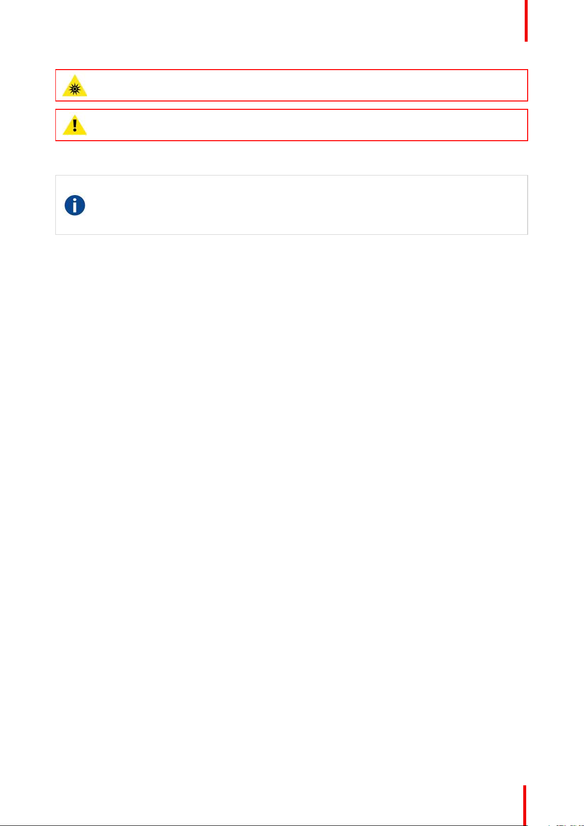
1.4.2 High Brightness precautions: Hazard Distance
HD
Hazard Distance (HD) is the distance measured from the projection lens at which the intensity or the
energy per surface unit becomes lower than the applicable exposure limit on the cornea or on the
skin. The light beam is considered (to be) unsafe for exposure if the distance from a person to the
light source is less than the HD.
Restriction Zone (RZ) based on the HD
The HD depends on the amount of lumens produced by the projector and the type of lens installed. See
chapter “General considerations”, page 8.
To protect untrained end users (as cinema visitors, spectators) the installation shall comply with the following
installation requirements: Operators shall control access to the beam within the hazard distance or install the
product at the height that will prevent spectators' eyes from being in the hazard distance. Radiation levels in
excess of the limits will not be permitted at any point less than 2.0 meter (SH) above any surface upon which
persons other than operators, performers, or employees are permitted to stand or less than 1.0 meter (SW)
lateral separation from any place where such persons are permitted to be. In environments where
unrestrained behavior is reasonably foreseeable, the minimum separation height should be greater than or
equal to 3.0 meter to prevent potential exposure, for example by an individual sitting on another individual's
shoulders, within the HD.
These values are minimum values and are based on the guidance provided in IEC 62471-5:2015 section
6.6.3.5.
The installer and user must understand the risk and apply protective measures based upon the hazard
distance as indicated on the label and in the user information. Installation method, separation height, barriers,
detection system or other applicable control measure shall prevent hazardous eye access to the radiation
within the hazard distance.
For example, projectors that have a HD greater than 1 m and emit light into an uncontrolled area where
persons may be present should be positioned in accordance with “the fixed projector installation” parameters,
resulting in a HD that does not extend into the audience area unless the beam is at least 2.0 meter above the
floor level. In environments where unrestrained behavior is reasonably foreseeable, the minimum separation
height should be greater than or equal to 3.0 meter to prevent potential exposure, for example by an individual
sitting on another individual's shoulders, within the HD. Sufficiently large separation height may be achieved
by mounting the image projector on the ceiling or through the use of physical barriers.
R5910888 /05 G60 15
Page 16
RA
TH
PR
RZ
HD
SW
1m
SW
SW
SW
HD
EXIT
SH
RA
TH
RZ
SH
(B) TOP VIEW(A) SIDE VIEW
PR
RESTRICTED
AREA
RESTRICTED
AREA
Safety
Image 1-2
A Side view.
B Top view.
RA Restricted Access location (boot area of
projector).
TH Theater.
RZ Restriction Zone in the theater.
SH Separation Height.
SWSeparation Width.
PR Projector.
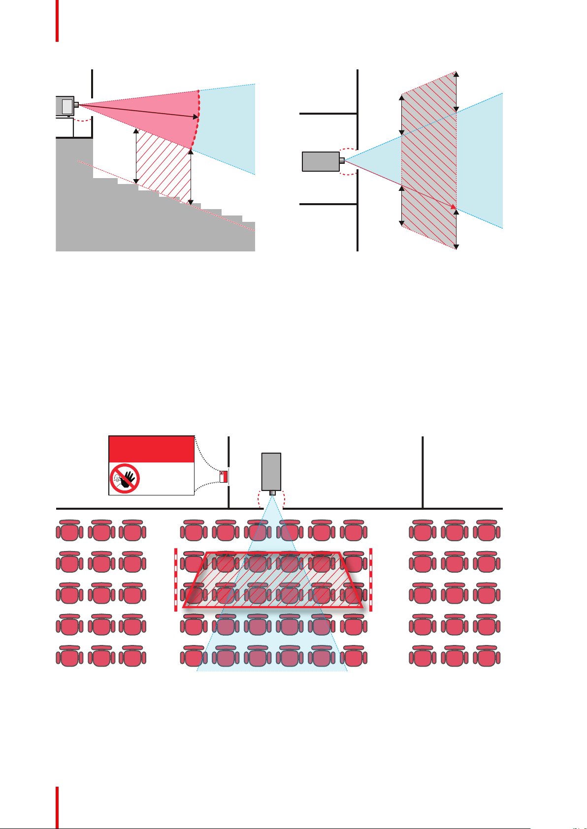
Based on national requirements, no person is allowed to enter the projected beam within the zone between
the projection lens and the related hazard distance (HD). This shall be physically impossible by creating
sufficient separation height or by placing barriers. The minimum separation height takes into account the
surface upon which persons other than operator, performers or employees are permitted to stand.
On Image 1-3 a typical setup is displayed. It must be verified if these minimum requirements are met. If
required a restricted zone (RZ) in the theater must be established. This can be done by using physical barrier,
like a red rope as illustrated in Image 1-3.
The restricted area sticker can be replaced by a sticker with only the symbol.
Image 1-3
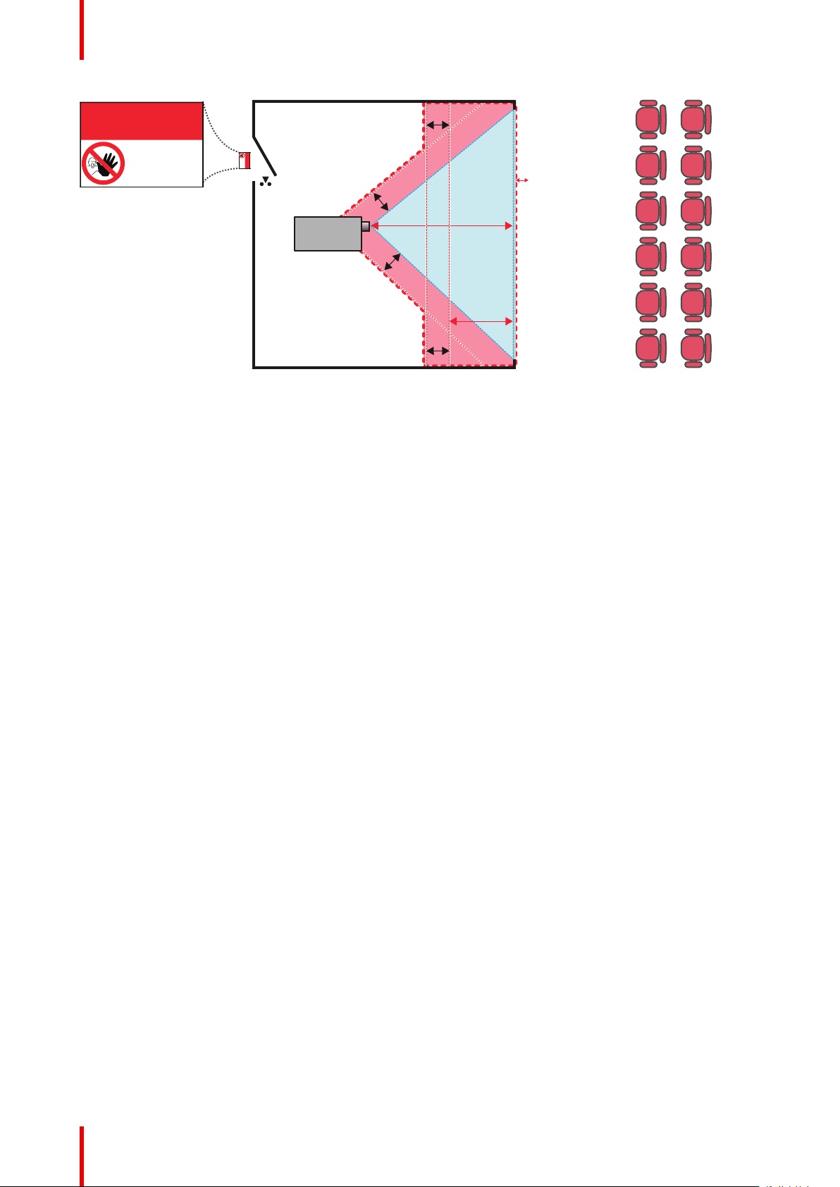
USA market
For LIPs (Laser Illuminated Projectors) installed in the USA market other restriction zone conditions apply.
LIPs for installation in restrained environment (cinema theaters, business rooms, class rooms, museums ...)
shall be installed at height vertically above the floor such that the bottom plane of the hazard distance zone
R5910888 /05 G6016
Page 17
Safety
shall be no lower than 2.5 meters above the floor. Horizontal clearance to the hazard distance zone shall be
not less than 1 meter. Alternatively, in case the height of the separation barrier for the horizontal clearance is
at least 1 meter high then the horizontal clearance (SW) can be reduced to:
• 0 meter if the height of the hazard zone is minimum 2.5 meter.
• 0.1 meter if the height of the hazard zone is minimum 2.4 meter.
• 0.6 meter if the height of the hazard zone is minimum 2.2 meter.
LIPs for installations in unrestrained environment (concerts, ...) shall be installed at a height vertically above
the floor such that the bottom plane of the Hazard distance Zone shall be no lower than 3 meters above the
floor. Horizontal clearance to the hazard distance zone shall be not less than 2.5 meters. Any human access
horizontally to the Hazard Zone, if applicable, shall be restricted by barriers. If human access is possible in an
unsupervised environment, the horizontal or vertical clearances shall be increased to prevent exposure to the
hazard distance zone.
The LIP shall be installed by Barco or by a trained and Barco-authorized installer or shall only be transferred to
laser light show variance holders. This is applicable for dealers and distributors since they may need to install
the LIP (demo install) and/or they transfer (sell, rent, lease) the LIP. Variance holders may currently hold a
variance for production of Class IIIB and IV laser light shows and/or for incorporating RG3 LIPs. Laser light
show variance can be requested via the FDA online eSubmitter portal or via FDA Form 3147 referencing to
Barco’s variance approval xxxx-xx-xxx.
The installation checklist for laser illuminated RG3 projectors must be fully completed after the installation.
The installation checklist can be downloaded from the Barco website. The last variance holder in the
distribution chain is responsible to maintain the installation checklist and to make it available on request of the
FDA. In case Barco is the last variance holder the checklist must be sent to pvg@barco.com.
In addition to temporary installations (e.g.: rental and staging, lease, events …) the following requirements
apply:
• Rental companies shall have a laser light show variance because they have direct relationship with the
installers of the rented equipment.
• This product shall be located in such a way that all propagating beam paths within the Restriction Zone,
and the audience can be directly observed at all times.
• Communication shall be maintained with other personnel assisting in surveillance of the LIP projection.
• In the event of any unsafe condition, immediately terminates (or designate the termination) of LIP
projection light.
Install one or more readily accessible controls to immediately terminate LIP projection light. The power input at
the projector side is considered as a reliable disconnect device. When required to switch off the projector,
disconnect the power cord at the projector side. In case the power input at the projector side is not accessible
(e. g. truss mount), the socket outlet supplying the projector shall be installed nearby the projector and be
easily accessible, or a readily accessible general disconnect device shall be incorporated in the fixed wiring.
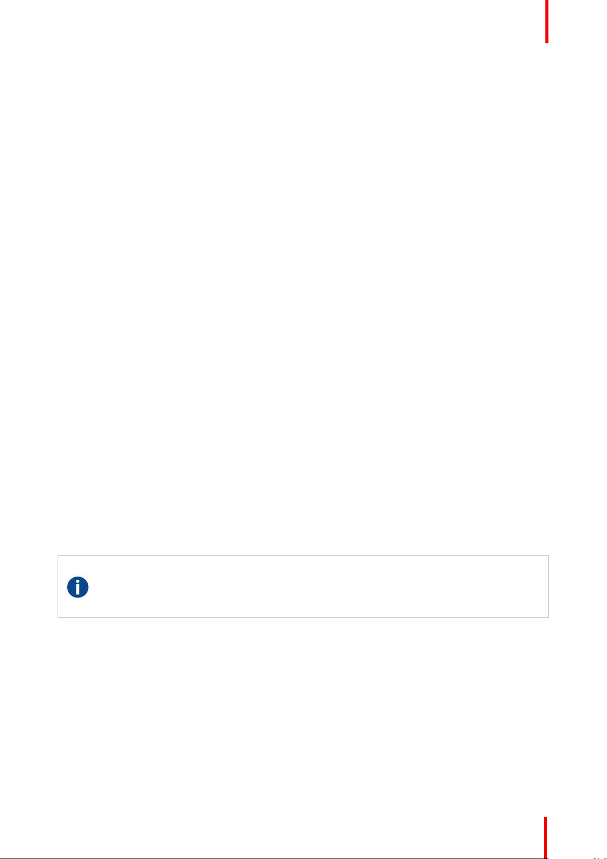
1.4.3 HD for fully enclosed projection systems
HD
Hazard Distance (HD) is the distance measured from the projection lens at which the intensity or the
energy per surface unit becomes lower than the applicable exposure limit on the cornea or on the
skin. The light beam is considered (to be) unsafe for exposure if the distance from a person to the
light source is less than the HD.
Restriction Zone (RZ) based on the HD
The projector is also suitable for rear projection applications; projecting a beam onto a defuse coated
projection screen. As displayed in Image 1-4 two areas should be considered: the restricted enclosed
projection area (RA) and the observation area (TH).
R5910888 /05 G60 17
Page 18
RA TH
sw
PD
HD
DIFFUSE
sw
RZ
sw
sw
PR
HD
REFLECTION
RESTRICTED
AREA
RESTRICTED
AREA
Safety
Image 1-4
RA Restricted Access location (enclosed projection
area).
PR Projector.
RZ Restriction Zone.
PD Projection Distance.
SWSeparation Width. Must be minimum 1 meter.
TH Theater (observation area).
For this type of setup 3 different HD shall be considered:
• HD as discussed in “High Brightness precautions: Hazard Distance”, page 15, relevant for intrabeam
exposure.
• HD
: the distance that has to be kept restrictive related to the reflected light from the rear projection
reflection
screen.
• HD
: the relevant distance to be considered while observing the diffuse surface of the rear projection
diffuse
screen.
As described in “High Brightness precautions: Hazard Distance”, page 15, it is mandatory to create a
restricted zone within the beam areas closer than any HD. In the enclosed projection area the combination of
two restricted zones are relevant: The restricted zone of the projected beam toward the screen; taking into
account 1 meter Separation Width (SW) from the beam onward. Combined with the restricted zone related to
the rear reflection from the screen (HD
The HD
reflection
distance equals 25% of the difference between the determined HD distance and the projection
); also taking into account a 1 meter lateral separation.
reflection
distance to the rear projection screen. To determine the HD distance for the used lens and projector model see
chapter “General considerations”, page 8.
HD
reflection
= 25% (HD – PD)
The light emitted from the screen within the observation shall never exceed the RG2 exposure limit,
determined at 10 cm. The HD
can be neglected if the measured light at the screen surface is below 5000
diffuse
cd/m² or 15000 LUX.
R5910888 /05 G6018
Page 19

Product overview 2
Overview
•
Main unit
• Input/Output (I/O) Panel
• Control panel
• Remote Control Unit (RCU)
R5910888 /05 G60
19
Page 20
1
2
76 6 68 9
3 54
Product overview
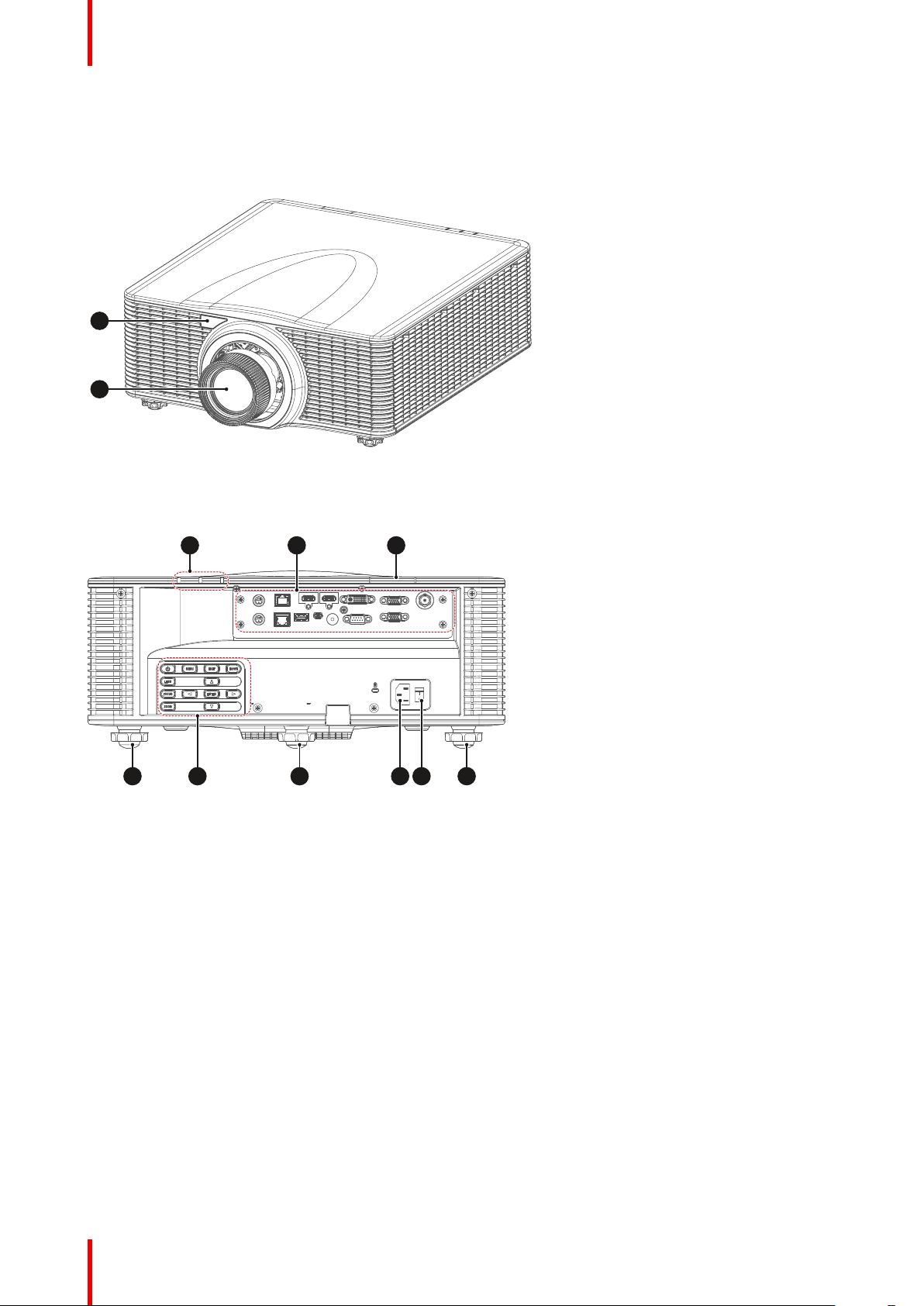
2.1 Main unit
Component location
Image 2-1
1 Remote receiver (Front)
2 Projection lens
Image 2-2
3 LED Status Indicator
4 Input/Output (I/O) Panel
5 Remote receiver (Top)
6 Adjustable feet
R5910888 /05 G6020
7 Control panel
8 Power socket (AC100-
240V, 50-60Hz)
9 Power switch
Page 21
Airflow
VGA-OUT
VGA-I N
DVI-D
HDMI-1
HDMI-2
3D SYNC OUT
3D SYNC I N
LAN
HDBas eT
RE MOTE IN
USB T ype-A
mini USB
3G-S DI
RS -232
1 2 4 5 6
7 8 9 10 11 12 13
3
Image 2-3
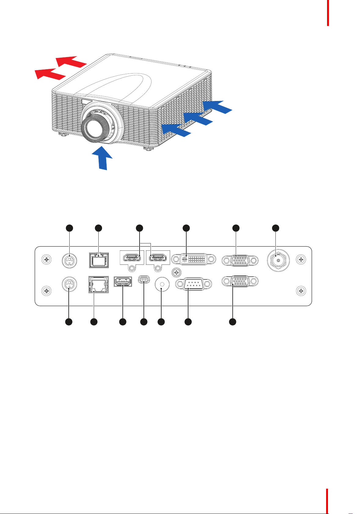
2.2 Input/Output (I/O) Panel
Product overview
Input and output ports location
Image 2-4
1 3D SYNC IN
2 HDBaseT connector
3 HDMI connector
4 DVI-D input connector
5 VGA-IN connector
6 3D-SDI connector
7 3D SYNC OUT
8 Networking connector RJ45
9 USB Type-A (Power out 5V, 0.5A)
10 Mini USB (Service)
11 Wired remote connector
12 RS232 connector
13 VGA-OUT connector
R5910888 /05 G60 21
Page 22
Z
IN PU TEX IT
ME NU
LE NS
FO CU S
OO M
EN TE R
1 2 3 6
7 8 9
11
10
5
12
4
Product overview
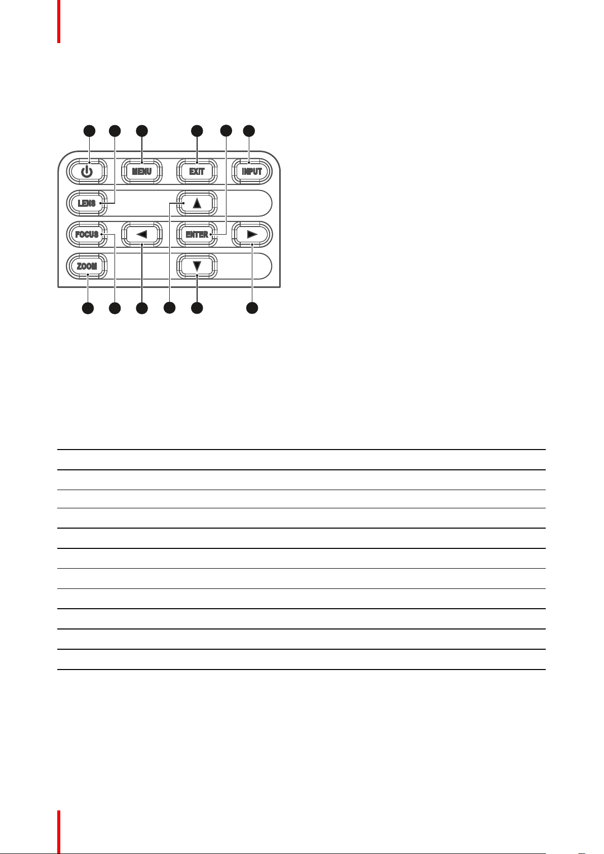
2.3 Control panel
Button location
Image 2-5
1 POWER
2 LENS
3 MENU
4 EXIT
5 ENTER
6 INPUT
7 ZOOM
8 FOCUS
9 LEFT
10 UP
11 DOWN
12 RIGHT
Button function
Button Function
POWER Turn the projector on or off.
LENS Adjust lens position.
MENU Show the main menu on screen.
EXIT Return to previous menu or exit menu if at top level.
ENTER Confirm the settings.
INPUT Select an input source.
ZOOM Adjust the image size.
FOCUS Adjust the image focus.
LEFT Navigate left through the menu.
UP Navigate up through the menu.
DOWN Navigate down through the menu.
RIGHT Navigate right through the menu.
R5910888 /05 G6022
Page 23
2.4 Remote Control Unit (RCU)
ON OFF
21 3
54 6
87 9
Gamma Bright Cont. PIP
0
Info
Mode
Auto Input
Menu Exit
Hot Key
Shutter
(AV Mute)
Pattern
Focus
Lens H
Lens V
Keystone H
Keystone V
Zoom
Enter
1
4
3
6
10
12
14
2
8
9
16
17
19
20
22
23
5
7
11
13
15
18
21
24
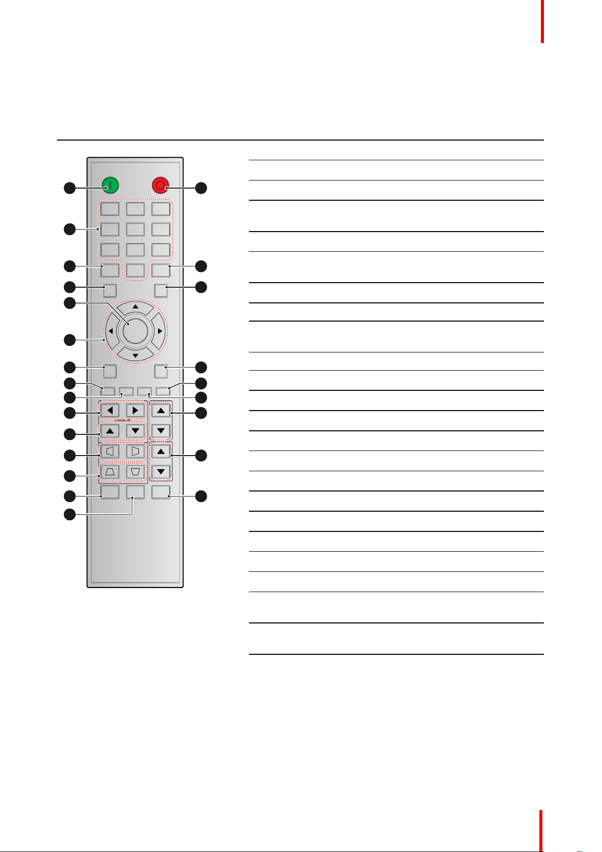
Button identification
Button location No. Button Function
1 ON Turn on the projector.
2 OFF Turn off the projector.
3 Number Input numbers (0-9).
4 Info Displays information on the source
image.
5 Mode Select a preset picture mode.
6 Auto Automatically synchronize the projector
to an input source.
7 Input Select an input source manually.
8 Enter Confirm an selection.
9 Arrow keys Use arrow keys to navigate through the
menu or select the appropriate settings.
Product overview
10 Menu Show the main menu on the screen.
11 Exit Back to previous Menu.
12 Gamma Set the gamma of the image.
13 PIP Set up the picture in picture (PIP) mode.
14 Brightness Set the brightness of the image.
15 Contrast Set the contrast of the image.
16 Lens H Adjust the image position horizontally.
17 Lens V Adjust the image position vertically.
18 Focus Adjust the image focus.
19 Keystone H Adjust a horizontally keystone image.
20 Keystone V Adjust a vertically keystone image.
21 Zoom Adjust the image size.
22 Shutter Momentarily turn off/on the screen (AV
Mute).
Setting the address
Before the RCU can be used, the projector address must be entered in the RCU.
To enter the address, handle as follow:
1. Press for at least 3 seconds on Hot Key (reference 23).
2. Enter the address with the numeric keys (reference 3). Always enter 2 digits.
23 Hot Key Select a specific function set as the hot
key.
24 Pattern Display test patterns.
E.g. for address 2, enter 02.
R5910888 /05 G60 23
Page 24

Product overview
Address 00 = broadcast address
Projector address can be set in Options → Remote settings → Projector address.
R5910888 /05 G6024
Page 25

Powering On/Off the projector
This chapter assumes that the power cord and (all) signal cables are securely connected. For
detailed instructions see installation manual.
Overview
•
Powering On the projector
• Powering Off the Projector
3
R5910888 /05 G60
25
Page 26

1
IN PU TEX IT
ME NU
LE NS
FO CU S EN TE R
ON OFF
21 3
54 6
2 3
4
Powering On/Off the projector
3.1 Powering On the projector
How to power On the projector
1. Power on the AC switch (1) and wait until the power button on the control panel is solid red.
Image 3-1
2. Turn on the projector by pressing the POWER button (2) on the control panel or the ON key (3) on the remote
control.
Image 3-2
The status LED (4) will flash orange. The startup screen will display and the status LED will turn to solid green.
Image 3-3
3. Turn on your source. The projector detects the source you selected and displays the image.
Note: If you connect multiple sources at the same time, press “Input” key on the control panel or on
the remote control to switch inputs.
WARNING: Do not look directly into the lens when the projector is turned on. The strong light might
cause permanent eye damage.
3.2 Powering Off the Projector
How to power Off the projector
1. Press the POWER button (2) on the control panel or the OFF key (5) on the remote control, a message
displays on the screen.
R5910888 /05 G6026
Page 27

IN PU TEX IT
ME NU
LE NS
FO CU S EN TE R
ON OFF
21 3
54 6
2 5
Powering On/Off the projector
Image 3-4
2. Press the POWER button or OFF key again to confirm, otherwise the message disappears after 5 seconds
and the projector remains on.
CAUTION: Don’t turn on the projector immediately after entering Standby mode.
R5910888 /05 G60 27
Page 28

Powering On/Off the projector
R5910888 /05 G6028
Page 29

User controls 4
Overview
•
On-Screen Display Menus
• Picture Menu
• Screen Menu
• Settings Menu
• Light Source Menu
• Options Menu
• 3D Menu
• Communications Menu
• Controlling the projector over network
• Using the web control center
• Using RS232 command by Telnet
R5910888 /05 G60
29
Page 30

1 2 3
User controls
4.1 On-Screen Display Menus
About OSD
The projector has On-Screen Display (OSD) menus that allow you to make image adjustments and change a
variety of settings.
Follow the steps below to use the OSD menu to configure the projector settings.
How to operate
1. To open the OSD menu, press Menu key on the control panel or remote control.
2. Use arrow keys to navigate through the menus and select appropriate settings.
3. Press Enter to enter the submenu or confirm a setting.
4. Press Exit to return to the previous menu or exit OSD menu if at top level.
Image 4-1
1 Main menu
2 Sub-menus
3 Settings
R5910888 /05 G6030
Page 31

4.2 Picture Menu
Overview
User controls
Image 4-2
Display Mode
Set the display mode to optimize the image performances for different display content.
• Bright : Best for high brightness applications.
• Presentation : Best for presentations when connected to a PC.
• Movie : Best for playing videos.
• sRGB : Best for high definition televisions.
• Blending : Best for multiple projector applications.
• DICOM SIM : Best for projecting monochrome medical images, such as X-ray diagram.
• User : The mode for the image settings saved by the user.
Wall Color
Set the wall color of the projector to achieve best color perfomance for a specific wall. The available options
are White and Gray 130.
Brightness
Adjust the luminous brightness of the projected image.
Contrast
Adjust the contrast of the projected image.
Sharpness
Adjust the clarity of detail in the projected image.
Color
Transform a video image from black and white to fully saturated color.
R5910888 /05 G60 31
Page 32

User controls
Tint
Adjust the color balance of red and green in video images.
Gamma
Select appropriate gamma value to optimize the image conformance to different applications.
• Video : Best for video or TV sources.
• Film : Best for home theater applications.
• Bright : Best for emphasizing brightness.
• CRT : Best for CRT monitors.
• DICOM : Best for medical images, such as X-ray diagram.
White Peaking
Adjust the brightness of whites in the projected image, with 0 being the minimal level and 100 being the
maximum.
Color Temperature
Adjust the color temperature of the projected image. The available options are Warm, Normal, and Cool.
Color Wheel Speed
The speed of the phosphor color wheel determines the image performance and the service life of the
projector.
• 2x : Extends the projector’s service life and reduces the noise level during operation.
• 3x : Increases the speed to eliminate the color artifacts for best image quality.
HSG Adjustment
HSG adjustment uses hue, saturation, and gain (HSG) to adjust the image’s primary colors (red, green and
blue) and secondary colors (cyan, magenta, and yellow). It helps calibrate the projected image to achieve
better color conformance to the surroundings, in consideration of factors such as screen size, ambient lighting,
and multiple projector applications.
Image 4-3
• Colors : Select the color for further adjustment.
• Hue : Adjust the hue of the selected color. The value reflects the number of degrees of rotation around the
chromaticity diagram from the original color. Increasing value indicates clockwise rotation, and decreasing
value, counterclockwise rotation.
R5910888 /05 G6032
Page 33

User controls
Image 4-4
• Saturation : Adjust the saturation of the selected color. The value indicates the color shifts from or towards
the white in the center of the chromaticity diagram.
• Gain : Adjust the gain of the selected color. Increase the value to brighten the image (add white to a color)
or decrease the value to darken the image (add black to a color).
• Reset to Default : Reset the color settings to factory default values.
Contrast Enhancement
Optimize the contrast ratio for different input sources.
• Off : Disable the contrast enhancement.
• Dynamic Black : Automatically adjust the contrast ratio for video sources.
• Extreme Black : Automatically increase the contrast ratio for blank (black) images.
Color Space
Select a color space that has been specifically tuned for the input signal. Use only for analog signals and
certain digital sources. The available options are Auto, RGB (0-255), RGB (16-235), and YUV.
Save to User
Save the user settings.
R5910888 /05 G60 33
Page 34

User controls
4.3 Screen Menu
Overview
Image 4-5
Aspect Ratio
Set the aspect ratio of the projected image. The available options are Auto, 4:3, 16:9, 16:10. Select Auto to
display the detected image size.
Pixel Phase
Adjust the phase of the pixel-sampling clock relative to the input signal. It helps to improve the quality of the
image that shows shimmer or noise after being optimized with pixel tracking. This function applies to analog
RGB signals only.
Pixel Track
Flickering or vertical stripes across the image indicates poor pixel tracking. Adjust the pixel track to optimize
the image quality across the screen. This function applies to analog RGB signals only.
Horz Position
Adjust the horizontal position of the display area within the lens offset range.
Vert Position
Adjust the vertical position of the display area within the lens offset range.
Digital Horz Zoom
Change the horizontal size of the projected area. After re-sizing the image with this function, use Digital Horz
Shift and Digital Vert Shift to move the image.
Digital Vert Zoom
Change the vertical size of the projected area. After re-sizing the image with this function, use Digital Horz
Shift and Digital Vert Shift to move the image.
R5910888 /05 G6034
Page 35

User controls
Digital Horz Shift
Adjust the horizontal position of the display area if it is resized through Digital Horz Zoom setting.
Digital Vert Shift
Adjust the vertical position of the display area if it is resized through Digital Vert Zoom setting.
Ceiling Mount
Flips the image upside down to project from a ceiling mount.
Rear Projection
Reverse the image to project behind a translucent screen.
Geometric Correction
Configure the geometric settings to reshape the image for different projection surface.
Image 4-6
• H. Keystone : Adjust the left and right side of the projected image to make it an even rectangle. It is used
for the images with unequal left and right sides.
Image 4-7
• V. Keystone : Adjust the top and bottom side of the projected image to make it an even rectangle. It is
used for the images with unequal top and bottom sides.
Image 4-8
• 4 - corner : Position the 4 corners of the image to have it fit a specific projection surface.
R5910888 /05 G60 35
Page 36

B C
D
E
A
H
FG
PPP
PPP
User controls
Image 4-9
• Grid Color : Set the grid color for 4-corner adjustment. The available options are purple or green.
• Reset : Reset geometric settings to factory default values.
• PC Mode : Enable PC mode to use PC software for more complicated geometric configuration.
PIP/PBP
PIP/PBP (picture in picture/picture by picture) mode allows displaying two images from two independent
sources. For more information on the PIP/PBP compatibility, See “Compatibility modes”, page 57.
Image 4-10
• PIP/PBP Enable : Select the appropriate PIP/PBP mode.
- Off : Disable PIP/PBP mode.
- PBP : Display two input sources simultaneously on the left and right sides of the screen.
- PIP : Display one input source on the main screen and the other input source in an inset window.
• Main Source : Select an input source for the main image.
• Sub Source : Select an input source for the second image.
• Layout : Adjust the layout of two images. In the layout chart below, the “P” indicates the main image:
PIP Size
PIP Layout
Small Medium
Large
PIP, Bottom Right
PIP, Bottom Left
R5910888 /05 G6036
Page 37

PPP
PPP
P
P
User controls
PIP Layout
Small Medium
PIP, Top Left
PIP, Top Right
PBP Layout
PBP, Main Left
• Size : Change the display size of the sub source in PIP mode.
• Swap : Swap the main source and sub source.
Source Key
Configure the source settings.
• Change Sources : Change the input source.
• List All Sources : List all input sources.
• Auto Source : Automatically detect and select input source.
PIP Size
Large
PBP, Main Right
Auto Image
Select the timing detection mode to support input signal with marginal quality. After the selection, the projector
will reacquire and lock the signal.
• Normal : Best for 4:3 input source.
• Wide : Best for 16:9 input source and most 4:3 input source.
Source Info
Display the information of the current input source.
R5910888 /05 G60 37
Page 38

User controls
4.4 Settings Menu
Overview
Image 4-11
Language
Select the language of the OSD menu. The available languages are English, Simplified Chinese, French,
German, Italian, Japanese, Korean, Russian, Spanish, Portuguese, Indonesian, Dutch.
Menu Location
Adjust the location of the OSD menu. The available positions are Left Top, Right Top, Center, Left Bottom and
Right Bottom.
Standby Power Mode
Select the power mode for the projector in standby status.
• Standby Mode : Minimum power consumption (0,5 Watt) which does not allow controlling the projector
over the network.
• Network Standby Mode : Low power consumption (< 2W) which allows the LAN module to enter sleep
mode and supports to be woken by Wake on LAN (WoL). When the LAN module is woken by WoL, the
projector is ready to receive commands over the network.
• Communication Mode : More power consumption that allows controlling the projector over the network.
Test Pattern
Select a test pattern. The available options are None, Grid, White, Black, Checkerboard, and Color Bars.
Direct Power On
Turn on this function to have the projector automatically turning on when connected to AC power.
Source in Power On
Turn on this function to have the projector automatically turning on when connected to HDMI input sources. It
only applies to the standby projector set to Communication Mode.
R5910888 /05 G6038
Page 39

User controls
Hot-Key Settings
Assign a specific function to the “Hot Key” button on the remote control. It allows you to use the function easily
without going through the OSD menus. The available functions for “Hot Key“ button are Blank Screen, Aspect
Ratio, Freeze Screen, and Projector Info.
Reset to Default
Reset all settings to the factory default values.
Service
The service menu is only available to Barco qualified service technitians.
4.5 Light Source Menu
Overview
Image 4-12
Light Source Mode
Set up the light source mode depending on the installations.
• Constant Power : Enable the Constant Power to meet different installation requirements.
• Constant Intensity : Select to maintain the current constant brightness and color settings. It is used after
the Constant Power is enabled.
• ECO : Set the projector to 50% constant brightness and color settings.
Constant Power
Select a value for the laser diode power. The value ranges from 0 to 99, which covers the power level from
30% to 100%. The power level can be managed to obtain the brightest image or longest service life.
Light Source Info
Display the total used hours of the laser diode and information on light sensor calibration
R5910888 /05 G60 39
Page 40

User controls
4.6 Options Menu
Overview
Image 4-13
Background Color
Select the background color when no signal is detected. The available options are Logo, Blue, Black, and
White.
Auto Shutdown
Set a time value for the projector to automatically turn off if no signal is detected within the specified time
period.
Sleep Timer
Set a time value for the projector to automatically turn off after operating for the specified amount of time.
Lens Function
Configure the lens settings.
R5910888 /05 G6040
Page 41

User controls
Image 4-14
• Focus : Use up and down arrow keys to adjust the focus of the projected image.
• Zoom : Use up or down arrow keys to zoom in or zoom out the projected image.
• Lens Shift : Use arrow keys to adjust the lens position to shift the projected area.
• Lens Memory : Save or apply the current lens position. The projector can save up to five records.
• Lens Lock : Lock the lens to prevent the lens motors from moving.
• Lens Calibration : Calibrate the lens to return it to the center position.
High Altitude
When the projector is operated at the altitude over 5,000ft (1,500m), enable this funtion to have the projector
fans operating at high speed to ensure proper air circulation.
PIN
Set a PIN number to protect the projector.
• PIN Protect : Enable PIN Protect to protect the project. A PIN number is required once this function is
enabled. (Default: 12345)
• Change PIN : Change the PIN number.
Remote Settings
Set up the remote receiver to control the communication between the projector and the remote control.
• Top : Enable or disable the top remote receiver.
• Front : Enable or disable the front remote receiver.
• HDBaseT : Select On to set the HDBaseT terminal as the remote receiver.
• Projector Address : Set a specific number for the projector as its address. The projector will only
responds to the remote control set with the same address.
Show Messages
Turning on or off the on screen messages showing the projector status information, such as input source, IP
address, and gamma.
LED Settings
Configure the status LED indicators to help identify the projector status. The definitions of the status LED are
discussed in the chapter “LED indication chart”, page 50.
• Keypad LED : Turn on or off the keypad backlight.
• Status LED : Turn on or off the status LED indicators, or select Warning/Errors Only to enable the
indicators for warning and error only.
Information
Display the projector information, such as model name, firmware version, and main input.
R5910888 /05 G60 41
Page 42

User controls
4.7 3D Menu
Overview
Image 4-15
3D
Enable the 3D function.
• Auto : The projector automatically enables 3D function when receiving the 3D input in 1.4a format.
• On : Turn on the 3D function manually.
3D Invert
3D video files and images combine two slightly different images (frames) of the same scene representing the
different views that the left and right eyes see. When these frames are displayed fast enough and viewed with
3D glasses synchronized with the left and right frames, the viewer’s brain then assembles the separate
images into a single 3D image. When the 3D image does not appear correctly, invert the sequence of the left
and right frames.
3D Format
Select a proper 3D format for the 3D input signal. The available options are Frame Packing, Side-by-Side
(Half), Top and Bottom, and Frame Sequential.
3D Sync Out
Set up the transmission of the 3D sync output signal.
• To Emitter : Send the 3D sync output signal to the emitter connected to the projector’s 3D sync out port.
• To Next Projector : For multiple projector applications, send the 3D sync output signal to next projector.
Frame Delay
Set a frame delay value for the projector to correct the time difference between the 3D signal being given and
the result being executed. This function works only when L/R Reference is set to Field GPIO.
When performing 3D blending on multiple projectors, set the frame delay for each projector to correct the none
synchronous images.
R5910888 /05 G6042
Page 43

User controls
L/R Reference
Select the reference for left and right (L/R) frames.
• 1ST Frame : When the projector generates 3D sync signal internally, select this option to set the first frame
of the input source as the projector’s left reference. If the 3D image does not appear correctly, use 3D
Invert function to swap the left and right frames.
• Field GPIO : When the projector receives external 3D sync signal through a 3D sync in cable, select this
option to have the projector’s L/R reference synchronizing with the 3D sync signal from the 3D sync in
cable.
DLP Link
Enable or disable the DLP Link function according to how the 3D sync signal is processed.
• On : Turn on DLP Link when the 3D sync signal is generated by the DLP Link technology built-in the
projector. DLP Link works only with the glasses that are compatible with DLP 3D technology and the 3D
function is enabled.
• Off : Turn off DLP Link when the 3D sync out signal is sent to an emitter or another projector through the
3D sync out port.
4.8 Communications Menu
Overview
Image 4-16
LAN
Configure the LAN settings for network communications.
• DHCP : Turn on DHCP to automatically acquire IP address, subnet mask, gateway, and DNS. If it is turned
off, manually enter the values for the network.
• IP Address : Set the projector’s IP address.
• Subnet Mask : Set the projector’s subnet mask.
• Default Gateway : Set the projector’s gateway.
• MAC Address : Display the MAC address.
• Apply : Apply the network settings.
R5910888 /05 G60 43
Page 44

User controls
Network
View and configure the projector’s network settings.
• Projector Name : Display the projector name.
• Show Network Messages : Select On to display network information as on screen messages.
• Network Factory Reset : Reset the network settings to factory default settings.
Serial Port Baud Rate
Select a serial port and baud rate. The available options include 1200, 2400, 4800, 9600, 14400, 19200,
38400, 57600, and 115200.
Serial Port Echo
When set to On, the projector will return the serial command it receives. The user can view the command that
has been sent to the projector.
Serial Port Path
Select the serial port path for the serial commands. The available options are RS232 or HDBaseT.
4.9 Controlling the projector over network
About controlling
This projector can be controlled remotely by a computer or other external devices through network connection.
It allows the user to control one or more projectors from a distant control center, such as powering the
projector on or off, and adjusting the image brightness or contrast. This projector is compatible with following
control devices and commands.
Image 4-17
• Crestron: The projector can be controlled with Crestron controller and related software, for example
Room- View®. (Port: 41794)
For more information, please visit http://www.crestron.com.
• Extron: The projector can be controlled with Extron devices. (Port: 3023)
For more information, please visit http://www.extron.com.
• PJ Link: The projector can be controlled with PJLink v1.0 commands. (Port: 4352)
For more information, please visit http://pjlink.jbmia.or.jp/english.
• AMX Device Discovery: The projector can be controlled with AMX devices. (Port: 9131)
For more information, please visit http://www.amx.com.
• Telnet: Support using RS232 commands via Telnet connection. (Port: 23)
For more information, see “Using RS232 command by Telnet”, page 47.
• HTTP: The projector can be controlled with a web page control center. (Port: 80)
For more information, see “Using the web control center”, page 45.
R5910888 /05 G6044
Page 45

1 2
User controls
For more information about the various types of external devices which can be connected to the
LAN / RJ45 port and remotely control the projector, as well as the supported commands for these
external devices, please contact the Support-Service directly.
4.10 Using the web control center
About web control center
Web control panel allows the user to configure various projector settings using a web browser from any
personal computer or mobile devices.
System requirement
To use the web control panel, make sure your devices and software meet the minimum system requirements.
• RJ45 cable (CAT-5e) or wireless dongle
• PC, laptop, mobile phone, or tablet installed with a web browser
• Compatible web browsers:
- Internet Explorer 11 or higher version
- Microsoft Edge 40 or higher version
- Firefox 57 or higher version
- Chrome 63 or higher version
- Safari 11 or higher version
• Operating system of the mobile devices:
- iOS 10 or higher version
- Android 5 or higher version
Overview of the web control center
Configure the projector settings using web browser.
Image 4-18
1 Menu
2 Settings
Menu Submenu
HOME Information View the projector information and firmware version details.
Main • Select the projector input sources.
Description
• Enable or disable the projector power, shutter, and messages.
R5910888 /05 G60 45
Page 46

User controls
Menu Submenu
Network • Configure the LAN settings.
Upgrade Upgrade the projector firmware.
MENU Picture Adjust the basic image settings, such as brightness and contrast.
Settings Enable ceiling mount projection and set up the standby mode.
Light
Source
Test Pattern Select a test pattern.
Description
• Set up the Crestron Control System (CCS) connection.
Select a light source mode and set the power level for constant power.
Accessing the web control panel
When network is available, connect the projector and the computer to the same network. Use the projector
address as the web URL to open the web control panel in a browser.
1. Check the projector address using the OSD menu.
• In a wired network, select Network > LAN > IP Address.
Make sure DHCP is enabled.
• In a wireless network, select Network > WLAN > Gateway.
2. Open a web browser and type the projector address in the address bar.
The web page redirects to the web control panel.
When network is not available, see Directly connect the projector to a computer.
Directly connect the projector to a computer
When network is not available, connect the projector to the computer directly using a RJ-45 cable, and
configure the network settings manually.
1. Assign IP address to the projector
• From the OSD menu, select Network > LAN.
• Turn off DHCP, and manually set the projector’s IP Address, Subnet Mask, and Gateway.
• Press Enter to confirm the settings.
Image 4-19
2. Assign IP address to the computer
• Set the Default Gateway and Subnet Mask of the computer to match the projector.
• Set the IP address of the computer to match the first three numbers of the projector.
For example, if the projector IP address is 192.168.000.100, set the computer IP address to 192.168.000.
xxx, where xxx is not 100.
R5910888 /05 G6046
Page 47

User controls
3. Open a web browser and type the projector address in the address bar.
The web page redirects to the web control panel.
4.11 Using RS232 command by Telnet
How to use
This projector supports using RS232 commands through Telnet connection.
1. Set up direct connection between the projector and computer. See block Directly connect the projector to a
computer, in “Controlling the projector over network”, page 44
2. Disable the firewall on the computer.
3. Open the command dialogue on the computer. For Windows 7 operating system, select Start > All Programs >
Accessories > Command Prompt.
4. Input the command “telnet ttt.xxx.yyy.zzz 23”.
Replace “ttt.xxx.yyy.zzz” with the projector IP address.
5. Press Enter on the computer keyboard.
Specification for RS232 by Telnet
• Telnet: TCP
• Telnet port: 23 (contact service team for more details)
• Telnet utility: Windows “TELNET.exe” (console mode).
• Disconnection for RS232-by-Telnet control normally: Close
• Below are the limitations for using Windows Telnet utility directly after TELNET connection is ready:
- There is less than 50 bytes for successive network payload for Telnet-Control application.
- There is less than 26 bytes for one complete RS232 command for Telnet-Control.
- Minimum delay for next RS232 command must be more than 200 (ms).
R5910888 /05 G60 47
Page 48

User controls
R5910888 /05 G6048
Page 49

Troubleshooting 5
If you experience a problem with your projector, please refer to the following information. If a
problem persists, please contact your local re-seller or service center.
Overview
•
LED indication chart
• Projector Problems
R5910888 /05 G60
49
Page 50

1 2 3
Troubleshooting
5.1 LED indication chart
Overview
Image 5-1
1 Light LED
2 Status LED
3 AV Mute LED
Explanation
Message
Green
Standby State
Power on
(Warm up)
Power on & Laser
diode on
AV mute is off
(Image is displayed)
AV mute is on
(Image is black)
Projector
communication
Firmware upgrade Flash-
Laser diode time has
expired
Steady Steady Steady
Steady Steady Steady
Steady Steady Steady
Steady Flash-
Light LED
Orange
Steady
Red Green
ing
ing
Status LED AV Mute LED
Orange
Flash-
ing
Flash-
ing
Red Green
Steady
Orange
Unit loses over 60%
initial luminance
Error
(Over temperature)
Error
(Fan failure)
Power key of the keypad is in steady red light when the projector enters standby mode.
R5910888 /05 G6050
Steady
Flash-
ing
Page 51

Troubleshooting
5.2 Projector Problems
No image appears on-screen
• Check if all the cables and the AC power are correctly connected. For more details, refer to the installation
manual.
• Check if the pins of the connectors are not crooked or broken.
• Check if the “Shutter (AV Mute)” function is disabled.
Partial, scrolling or incorrectly displayed image
• Press “Auto” on the remote control to detect input signal automatically.
• If you are using a PC, set the PC’s resolution lower or equal to WUXGA (1920 × 1200).
• If you are using a Notebook:
- Set the resolution lower or equal to WUXGA (1920 × 1200).
- Press the appropriate keys listed below for your notebook manufacturer to send signal out from
notebook to projector. Example: [Fn]+[F4]
Acer [Fn]+[F5]
Asus [Fn]+[F8]
Dell [Fn]+[F8]
Gateway [Fn]+[F4]
BM/Lenovo [Fn]+[F7]
HP/Compaq [Fn]+[F4]
NEC [Fn]+[F3]
Toshiba Fn]+[F5]
Mac Apple System Preference > Display > Arrangement > Mirror display
• If you experience difficulty changing resolutions or your monitor freezes, restart all equipments including
the projector.
Image is flickering and shimmering
• Adjust the pixel phase and pixel track of the projector. See “Pixel Phase“ and “Pixel Track“ in chapter
“Screen Menu”, page 34.
Image is fuzzy and blurry
• Press the “Focus ▲” or “Focus ▼” button on the remote control or control panel to adjust the image focus
until it is sharp and clear. To adjust focus from OSD menu, select “Options > Lens function > Focus“.
• Make sure the projection screen is in proper distance with the projector. For projection distances of each
lens, see chapter installation manual.
Stretched when displaying 16:10 DVD videos
• Set appropriate aspect ratio for the projector by selecting “Screen > Aspect Ratio“ from the OSD menu.
• Set the aspect ratio to 16:10 on the DVD player.
Image is too small or too large
• Adjust the image size by pressing the “Zoom ▲” or “Zoom ▼” button on the remote control or control panel,
or selecting “Options > Lens function > Zoom“ from the OSD menu.
• Adjust the distance between the projector and the screen.
• Adjust the aspect ratio by selecting “Screen > Aspect Ratio“ from the OSD menu.
R5910888 /05 G60 51
Page 52

Troubleshooting
Image is not an even rectangle
• Perform keystone correction by pressing the “Keystone H“ and “Keystone V“ button on the remote control,
or using “Screen > Geometric Correction > V. Keystone or “H. Keystone” from the OSD menu.
Image is reversed
• To reverse the image, enable rear projection by selecting “Screen > Rear Projection > On” from the OSD
menu.
The projector stops responding to all controls
• If possible, turn off the projector, then unplug the power cord and wait at least 60 seconds before
reconnecting power.
If the remote control does not work
• Check if the operating angle of the remote control is pointed within ±30° (front and back) to the remote
receivers on the projector. Make sure there are any obstructions between the remote control and the
projector.
• Check the remote batteries. Make sure batteries are inserted correctly. Replace the batteries if they are
used up.
• Ensure you have set the correct IR code to the remote control. See “Remote Settings“ in the chapter
“Options Menu”, page 40.
R5910888 /05 G6052
Page 53

Specifications A
Overview
•
Product specification of the G60-W7
• Product specification of the G60-W8
• Product specification of the G60-W10
• Compatibility modes
• Dimensions of the G60
• Ceiling mount
R5910888 /05 G60
53
Page 54

Specifications
A.1 Product specification of the G60-W7
Specifictions
Projector type Single chip DLP laser phosphor projector
Resolution 1,920 x 1,200 (WUXGA)
Brightness 6,300 ANSI lumens 6,600 center lumens 7,000 ISO lumens
Contrast ratio 1,200:1 sequential; 6,000:1 dynamic; Extreme black: 100,000:1
Brightness uniformity 85%
Aspect ratio 16:10
Lens type G-lenses - 0.36:1 / 0.75-0.95:1 / 0.95-1.22:1 / 1.22-1.52:1 / 1.52-2.92:1 /
2.90-5.50:1
Optical lens shift Vertical up to 100%, depending on lens
Horizontal up to 30%, depending on lens
Motorized zoom and focus
Motorized lens shift
Color correction Yes
CLO (constant light output) Yes
Light source Laser phosphor
Light source lifetime Up to 20,000hrs
Sealed DLP™ core Yes
Orientation 360° rotation, no restrictions
3D Active stereoscopic 3D
Image processing Embedded warp & blend possible via Ptoolset
Keystone correction Yes
Inputs 2x HDMI 1.4 / DVI-D / HDBaseT / 3G-SDI / VGA (D-Sub 15 pin) / RJ 45
Ethernet / RS232 in
Input resolutions Up to 1,920 x 1,200 @ 60Hz
refresh rates:
24Hz to 120Hz for 720p (1280x720) and 24Hz to 60Hz for WUXGA
(1920x1200)
Software tools Projector Toolset
Control IR, RS232, RJ45, 3.5mm phone jack for wired remote
Network connection 10/100 Ethernet, RJ45
Power requirements 100-240V / 50-60Hz
Power consumption 520W nominal, 600W maximum
BTU per hour 1,780 BTU/h nominal; 2,050 BTU/h maximum
Standby power less than 0.5W
Noise level (typical at 25°C/
77°F)
Operating temperature 5 - 40 °C (sea level)
R5910888 /05 G6054
36dB(A) - 40dB(A) depending on the used mode
Page 55

Specifications
Storage temperature -10 to 60 °C
Operating humidity 10 - 85% RH, non-condensing
Storage humidity 5 - 90% RH, non-condensing
Dimensions (WxLxH) without feet: 484 x 529 x 195 mm / 19.06 x 20.83 x 7.68 in
Weight without lens: 16.9 kg / 37.3 lbs
Standard accessories Power cord, wireless remote control
Certifications CE, FCC Class A, cTUVUS, CCC, EAC, KCC, RCM, BIS, BSMI
Warranty Limited 3 years parts and labor
A.2 Product specification of the G60-W8
Specifictions
Projector type Single chip DLP laser phosphor projector
Resolution 1,920 x 1,200 (WUXGA)
Brightness 7,300 ANSI lumens 7,700 center lumens 8,200 ISO lumens
Contrast ratio 1,200:1 sequential; 6,000:1 dynamic; Extreme black: 100,000:1
Brightness uniformity 85%
Aspect ratio 16:10
Lens type G-lenses - 0.36:1 / 0.75-0.95:1 / 0.95-1.22:1 / 1.22-1.52:1 / 1.52-2.92:1 /
2.90-5.50:1
Optical lens shift Vertical up to 100%, depending on lens
Horizontal up to 30%, depending on lens
Motorized zoom and focus
Motorized lens shift
Color correction Yes
CLO (constant light output) Yes
Light source Laser phosphor
Light source lifetime Up to 20,000hrs
Sealed DLP™ core Yes
Orientation 360° rotation, no restrictions
3D Active stereoscopic 3D
Image processing Embedded warp & blend possible via Ptoolset
Keystone correction Yes
Inputs 2x HDMI 1.4 / DVI-D / HDBaseT / 3G-SDI / VGA (D-Sub 15 pin) / RJ 45
Ethernet / RS232 in
Input resolutions Up to 1,920 x 1,200 @ 60Hz
refresh rates:
24Hz to 120Hz for 720p (1280x720) and 24Hz to 60Hz for WUXGA
(1920x1200)
Software tools Projector Toolset
R5910888 /05 G60 55
Page 56

Specifications
Control IR, RS232, RJ45, 3.5mm phone jack for wired remote
Network connection 10/100 Ethernet, RJ45
Power requirements 100-240V / 50-60Hz
Power consumption 635W nominal, 730W maximum
BTU per hour 2,170 BTU/h nominal; 2,500 BTU/h maximum
Standby power less than 0.5W
Noise level (typical at 25°C/
77°F)
Operating temperature 5 - 40 °C (sea level)
Storage temperature -10 to 60 °C
Operating humidity 10 - 85% RH, non-condensing
Storage humidity 5 - 90% RH, non-condensing
Dimensions (WxLxH) without feet: 484 x 529 x 195 mm / 19.06 x 20.83 x 7.68 in
Weight without lens: 17.4 kg / 38.4 lbs
Standard accessories Power cord, wireless remote control
Certifications CE, FCC Class A, cTUVUS, CCC, EAC, KCC, RCM, BIS, BSMI
Warranty Limited 3 years parts and labor
36dB(A) - 40dB(A) depending on the used mode
A.3 Product specification of the G60-W10
Specifictions
Projector type Single chip DLP laser phosphor projector
Resolution 1,920 x 1,200 (WUXGA)
Brightness 9,000 ANSI lumens 9,500 center lumens 10,200 ISO lumens
Contrast ratio 1,200:1 sequential; 6,000:1 dynamic; Extreme black: 100,000:1
Brightness uniformity 85%
Aspect ratio 16:10
Lens type G-lenses - 0.36:1 / 0.75-0.95:1 / 0.95-1.22:1 / 1.22-1.52:1 / 1.52-2.92:1 /
2.90-5.50:1
Optical lens shift Vertical up to 100%, depending on lens
Horizontal up to 30%, depending on lens
Motorized zoom and focus
Motorized lens shift
Color correction Yes
CLO (constant light output) Yes
Light source Laser phosphor
Light source lifetime Up to 20,000hrs
Sealed DLP™ core Yes
Orientation 360° rotation, no restrictions
R5910888 /05 G6056
Page 57

Specifications
3D Active stereoscopic 3D
Image processing Embedded warp & blend possible via Ptoolset
Keystone correction Yes
Inputs 2x HDMI 1.4 / DVI-D / HDBaseT / 3G-SDI / VGA (D-Sub 15 pin) / RJ 45
Ethernet / RS232 in
Input resolutions Up to 1,920 x 1,200 @ 60Hz
refresh rates:
24Hz to 120Hz for 720p (1280x720) and 24Hz to 60Hz for WUXGA
(1920x1200)
Software tools Projector Toolset
Control IR, RS232, RJ45, 3.5mm phone jack for wired remote
Network connection 10/100 Ethernet, RJ45
Power requirements 100-240V / 50-60Hz
Power consumption 935W nominal, 1080W maximum
BTU per hour 3,190 BTU/h nominal; 3,690 BTU/h maximum
Standby power less than 0.5W
Noise level (typical at 25°C/
77°F)
Operating temperature 5 - 40 °C (sea level)
Storage temperature -10 to 60 °C
Operating humidity 10 - 85% RH, non-condensing
Storage humidity 5 - 90% RH, non-condensing
Dimensions (WxLxH) without feet: 484 x 529 x 195 mm / 19.06 x 20.83 x 7.68 in
Weight without lens: 22.7 kg / 50.1 lbs
Standard accessories Power cord, wireless remote control
Certifications CE, FCC Class A, cTUVUS, CCC, EAC, KCC, RCM, BIS, BSMI
Warranty Limited 3 years parts and labor
36dB(A) - 40dB(A) depending on the used mode
A.4 Compatibility modes
Timing table
Signal type
PC 640x350 85 V V V
Resolution
640x400 85 V V V V
640x480 59 V V V
640x480 60 V V V V
640x480 72 V V V V
640x480 75 V V V V
640x480 85 V V V V
720x400 60 V V V V
720x400 85 V
Frame rate
(Hz)
VGA HDMI1/2 DVI
HDBa-
seT
R5910888 /05 G60 57
3G-SDI
Page 58

Specifications
Signal type
Resolution
Frame rate
(Hz)
VGA HDMI1/2 DVI
HDBa-
768x480 60 V V V
768x480 75 V V V
768x480 85 V V V
800x600 50 V V V
800x600 56 V V V V
800x600 60 V V V V
800x600 72 V V V V
800x600 75 V V V V
800x600 85 V V V V
848x480 50 V V V
848x480 60 V V V
848x480 75 V V V
848x480 85 V V V
960x600 50 V V V
960x600 60 V V V
960x600 75 V V V
960x600 85 V V V
1024x768 60 V V V V
1024x768 75 V V V V
1024x768 85 V V V V
1024x768 120 V V V V
1064x600 50 V V V
1064x600 60 V V V
1064x600 75 V V V
1064x600 85 V V V
1152x720 50 V V V
1152x720 60 V V V
1152x720 75 V V V
1152x720 85 V V V
1152x864 60 V V V V
1152x864 70 V V V V
1152x864 75 V V V V
1152x864 85 V V V V
1224x768 50 V V V
1224x768 60 V V V
1224x768 85 V V V
1280x720 50 V V V
1280x720 60 V V V V
1280x720 75 V V V V
1280x720 85 V V V V
1280x720 120 V V V
1280x768 60 V V V V
1280x768 75 V V V V
1280x768 85 V V V V
1280x800 50 V V V V
1280x800 60 V V V V
1280x800 75 V V V V
1280x800 85 V V V V
1280x960 50 V V V
1280x960 60 V V V V
1280x960 75 V V V V
1280x960 85 V V V V
seT
3G-SDI
R5910888 /05 G6058
Page 59

Specifications
Signal type
Resolution
Frame rate
(Hz)
VGA HDMI1/2 DVI
1280x1024 50 V V V
1280x1024 60 V V V V
1280x1024 75 V V V V
1280x1024 85 V V V V
1360x768 50 V V V
1360x768 60 V V V
1360x768 75 V V V
1360x768 85 V V V
1366x768 60 V V V V
1400x900 60 V V
1400x1050 50 V V V
1400x1050 60 V V V V
1400x1050 75 V V V V
1440x900 60 V V V V
1440x900 75 V V V
1600x900 60 V V V
1600x1200 50 V V V
1600x1200 60 V V V V
1680x1050 50 V V V
1680x1050 60 V V V V
1704x960 50 V V V
1704x960 60 V V V
1728x1080 50 V V V
1728x1080 60 V V V
1864x1050 50 V V V
1864x1050 60 V V V
1920X1080 50 V V V
1920X1080 60 V V V V
1920X1200RB 60 V V V V
1920X1200RB 50 V V V V
SDTV 480i 60 V V V V
576i 50 V V V V
EDTV 480p 60 V V V V
576p 50 V V V V
HDTV 1080i 25 V V V V
1080i 29 V V V V
1080i 30 V V V V
720p 50 V V V V
720p 59 V V V V
720p 60 V V V V
1080s 23 V
1080s 24 V
1080p 23 V V V V
1080p 24 V V V V
1080p 25 V V V V
1080p 29 V V V V
1080p 30 V V V V
1080p 50 V V V V
1080p 59 V V V V
1080p 60 V V V V
HDBa-
seT
3G-SDI
R5910888 /05 G60 59
Page 60

Specifications
Signal type
Mandatory3DFrame Packing 1080p 24 V V V
Frame
Sequential
3D (single
and
multiple)
SD-SDI 480i YcbCr422 10bit 59.94 V
HD-SDI 720p Ycb-Cr422 10bit 50 V
3GA-SDI 1080p Ycb-Cr422
3GB-SDI 1080p Ycb-Cr422
Resolution
Frame Packing 720p 50 V V V
Side by Side 1080i 50 V V V
Top and Bottom 720p 50 V V V
Top and Bottom 1080p 24 V V V
800x600 120 V V V
1024x768 120 V V V
1280x720 120 V V V
576i YcbCr422 10bit 50 V
720p Ycb-Cr422 10bit 59.94 V
720p Ycb-Cr422 10bit 60 V
1080i Ycb-Cr422 10bit 50 V
1080i Ycb-Cr422 10bit 59.94 V
1080i Ycb-Cr422 10bit 60 V
1080p Ycb-Cr422
10bit
1080p Ycb-Cr422
10bit
1080p Ycb-Cr422
10bit
1080p Ycb-Cr422
10bit
1080p Ycb-Cr422
10bit
1080sF Ycb-Cr422
10bit
1080sF Ycb-Cr422
10bit
1080sF Ycb-Cr422
10bit
10bit
10bit
With 352M Payload ID
Frame rate
(Hz)
60 V V V
60 V V V
60 V V V
23.98 V
24 V
25 V
29.97 V
30 V
25 V
29.97 V
30 V
50 V
59.94 V
60 V
50 V
59.94 V
60 V
VGA HDMI1/2 DVI
HDBa-
seT
3G-SDI
PIP/PBP Compatibility
PIP/PBP
Matrix
VGA V V V V V
DVI-D V V V V V
HDMI-1 V V V V V
HDMI-2 V V V V V
R5910888 /05 G6060
VGA DVI-D HDMI-1 HDMI-2 3G-SDI HDBaseT
Page 61

242.0
111.3
73.6
195.0
184.3
206.3
Specifications
PIP/PBP
Matrix
3G-SDI V V V V V
HDBaseT V V V V V
PIP/PBP does not support 3D input.
VGA DVI-D HDMI-1 HDMI-2 3G-SDI HDBaseT
A.5 Dimensions of the G60
CAUTION: Avoid installing the projector near a heat source.
Front view
Image A-1: Dimensions given in millimeters.
Rear view
Image A-2: Dimensions given in millimeters.
R5910888 /05 G60 61
Page 62

484.0
529.0
509.0
Specifications
Top view
Image A-3: Dimensions given in millimeters.
A.6 Ceiling mount
About ceiling mount
CAUTION: Be sure to use the correct screw size. Screw Length will vary depending on the
thickness of the mounting plate.
CAUTION: Be sure to keep at least 30 mm gap between the ceiling and the bottom of the projector.
R5910888 /05 G6062
Page 63

Projector mounting holes
280.0
140.0
100.0
100.0
310.0
310.0
99.0
99.0
280.0
4 - M6 x1.0P L10
Specifications
Image A-4: Dimensions given in millimeters.
R5910888 /05 G60 63
Page 64

Specifications
R5910888 /05 G6064
Page 65

Environmental
information
Overview
•
China RoHS compliance
• Taiwan RoHS compliance
• Turkey RoHS compliance
• Disposal information
• Production address
• Contact information
• Download Product Manual
B
R5910888 /05 G60
65
Page 66

10
Environmental information
B.1 China RoHS compliance
中国大陆 RoHS (Information for China ROHS compliance)
根据中国大陆《电器电子产品有害物质限制使用管理办法》(也称为中国大陆RoHS), 以下部分列出了
Barco产品中可能包含的有毒和/或有害物质的名称和含量。中国大陆RoHS指令包含在中国信息产业部MCV标
准:“电子信息产品中有毒物质的限量要求”中。
According to the “Management Methods for the Restriction of the Use of Hazardous Substances in Electrical
and Electronic Products” (Also called RoHS of Chinese Mainland), the table below lists the names and
contents of toxic and/or hazardous substances that Barco’s product may contain. The RoHS of Chinese
Mainland is included in the MCV standard of the Ministry of Information Industry of China, in the section “Limit
Requirements of toxic substances in Electronic Information Products”.
零件项目(名称)
Component name
外壳
Shell
主板
Motherboard
引擎模块
Engine module
雷射光源模组
Laser light source module
风扇
Fan
铁件
Iron frame
线材
Wire
遥控器
Remote control
包装
Package
有毒有害物质或元素
Hazardous substances and elements
铅
(Pb)
X O X O O O
X O O O O O
X O O O O O
X O O O O O
X O O O O O
X O O O O O
X O X O O O
X O O O O O
O O O O O O
汞
(Hg)
镉
(Cd)
六价铬
(Cr6+)
多溴联苯
(PBB)
多溴二苯
醚
(PBDE)
本表格依据SJ/T 11364的规定编制
This table is prepared in accordance with the provisions of SJ/T 11364.
O: 表示该有毒有害物质在该部件所有均质材料中的含量均在 GB/T 26572 标准规定的限量要求以下.
O: Indicates that this toxic or hazardous substance contained in all of the homogeneous materials for this
part is below the limit requirement in GB/T 26572.
X: 表示该有毒有害物质至少在该部件的某一均质材料中的含量超出 GB/T 26572 标准规定的限量要求.
X: Indicates that this toxic or hazardous substance contained in at least one of the homogeneous materials
used for this part is above the limit requirement in GB/T 26572.
在中国大陆销售的相应电子信息产品(EIP)都必须遵照中国大陆《电子电气产品有害物质
限制使用标识要求》标准贴上环保使用期限(EFUP)标签。Barco产品所采用的EFUP标签
(请参阅实例,徽标内部的编号使用于指定产品)基于中国大陆的《电子信息产品环保使用
期限通则》标准。
R5910888 /05 G6066
Page 67

Environmental information
All Electronic Information Products (EIP) that are sold within Chinese Mainland must
comply with the “Marking for the restriction of the use of hazardous substances in electrical
and electronic product” of Chinese Mainland, marked with the Environmental Friendly Use
Period (EFUP) logo. The number inside the EFUP logo that Barco uses (please refer to the
photo) is based on the “General guidelines of environment-friendly use period of electronic
information products” of Chinese Mainland.
B.2 Taiwan RoHS compliance
限用物質含有情況標示聲明書 (Declaration of the Presence Condition of the Restricted
Substances Marking)
限用物質及其化學符號
Restricted substances and its chemical symbols
單元
Unit
塑膠外殼
Plastic shell
電源供應器
Power supply
印刷電路板
Printed circuit board
絕緣墊片
Insulating gasket
光學鏡片
Optical lenses
雷射模組
Laser module
風扇模組
Fan module
鐵件
Iron frame
線材
wire (interlock switch/power cord)
鉛
Lead
(Pb)
— O O O O O
— O O O O O
— O O O O O
O O O O O O
— O O O O O
— O O O O O
— O O O O O
—
— O — O O O
汞
Mercu-
ry
(Hg)
O O O O O
鎘
Cadmi-
um
(Cd)
六價鉻
Hexava-
lent
chromi-
um
(Cr6+)
多溴聯苯
Polybromi-
nated
biphenyls
(PBB)
多溴二苯醚
Polybromi-
diphenyl
nated
ethers
(PBDE)
喇叭
Speaker
馬達
Motor
自復式保險絲
Resettable fuse (polyswitch)
— O O O O O
— O O O O O
O O O O O O
R5910888 /05 G60 67
Page 68

Environmental information
限用物質及其化學符號
Restricted substances and its chemical symbols
單元
Unit
配件(如:遙控器等)
Accessories (remote control, etc.)
備考1.〝超出0.1 wt %〞及〝超出0.01 wt %〞係指限用物質之百分比含量超出百分比含量基準值。
Note 1:“Exceeding 0.1 wt %” and “exceeding 0.01 wt %” indicate that the percentage content of the
restricted substance exceeds the reference percentage value of presence condition.
備考2.〝〇〞係指該項限用物質之百分比含量未超出百分比含量基準值。
Note 2:“〇” indicates that the percentage content of the restricted substance does not exceed the
percentage of reference value of presence.
備考3.〝—〞係指該項限用物質為排除項目。
Note 3:The “—” indicates that the restricted substance corresponds to the exemption.
備註: 此RoHS表格適用於以下產品型號: G60-W7, G60-W8, G60-W10
Hint: This RoHS table is suitable for following models: G60-W7, G60-W8, G60-W10
鉛
Lead
(Pb)
— O O O O O
汞
Mercu-
ry
(Hg)
鎘
Cadmi-
um
(Cd)
六價鉻
Hexava-
lent
chromi-
um
(Cr6+)
多溴聯苯
Polybromi-
nated
biphenyls
(PBB)
多溴二苯醚
Polybromi-
B.3 Turkey RoHS compliance
nated
diphenyl
ethers
(PBDE)
Turkey RoHS compliance
Türkiye Cumhuriyeti: AEEE Yönetmeliğine Uygundur.
[Republic of Turkey: In conformity with the WEEE Regulation]
B.4 Disposal information
Disposal Information
Waste Electrical and Electronic Equipment
This symbol on the product indicates that, under the European Directive 2012/19/EU governing waste
from electrical and electronic equipment, this product must not be disposed of with other municipal waste.
Please dispose of your waste equipment by handing it over to a designated collection point for the recycling of
waste electrical and electronic equipment. To prevent possible harm to the environment or human health from
uncontrolled waste disposal, please separate these items from other types of waste and recycle them
responsibly to promote the sustainable reuse of material resources.
For more information about recycling of this product, please contact your local city office or your municipal
waste disposal service.
For details, please visit the Barco website at: http://www.barco.com/AboutBarco/weee
R5910888 /05 G6068
Page 69

Environmental information
Disposal of batteries in the product
This product contains batteries covered by the Directive 2006/66/EC which must be collected and
disposed of separately from municipal waste.
If the battery contains more than the specified values of lead (Pb), mercury (Hg) or cadmium (Cd), these
chemical symbols will appear below the crossed-out wheeled bin symbol.
By participating in separate collection of batteries, you will help to ensure proper disposal and to prevent
potential negative effects on the environment and human health.
B.5 Production address
Producer
Barco NV (BELGIUM) Entertainment Division
Beneluxpark 21, 8500 Kortrijk, Belgium
Made in information
The made in country is indicated on the product ID label on the product itself.
Production date
The month and year of production is indicated on the product ID label on the product itself.
B.6 Contact information
Barco contact information
Registered office address: President Kennedypark 35, 8500 Kortrijk, Belgium
Contact address: Beneluxpark 21, 8500 Kortrijk, Belgium
Importers contact information
To find your local importer, contact Barco directly or one of Barco's regional offices via the contact information
given on Barco's web site, www.barco.com.
B.7 Download Product Manual
Download Product Manual
Product manuals and documentation are available online at www.barco.com/td.
Registration may be required; follow the instructions given on the website.
IMPORTANT! Read Installation Instructions before connecting equipment to the mains power supply.
R5910888 /05 G60 69
Page 70

Environmental information
R5910888 /05 G6070
Page 71

Glossary
HD
Hazard Distance (HD) is the distance measured from the projection lens at which the intensity or the energy
per surface unit becomes lower than the applicable exposure limit on the cornea or on the skin. The light beam
is considered (to be) unsafe for exposure if the distance from a person to the light source is less than the HD.
R5910888 /05 G60
71
Page 72

Glossary
R5910888 /05 G6072
Page 73

Index
Numbers/Symbols
3D Menu 42
A
Address 69
C
Ceiling mount
Holes 62
Communications Menu 43
Compatibility modes 57
Control panel 22
D
Dimensions 61
Download
Product manual 69
E
Electrical shock 10
Enclosed projection 17
Environmental information 65
Disposal information 68
RoHS compliance
China 66
Taiwan 67
Turkey 68
H
Hazard Distance 15, 17
Hazardous Chemicals 13
HD for G60-W10
Safety 9
High Brightness precautions 15
I
Importer 69
Input/Output 21
Instructions
Safety 10
L
Labels
Safety 13
Safety G60-W10 14
Safety G60-W7 13
Safety G60-W8 14
Laser safety precautions G60-W10
Safety 9
Laser safety precautions G60-W7
Safety 8
Laser safety precautions G60-W8
Safety 8
LED Indication chart 50
Light Source Menu 39
M
Main unit 20
F
Fire hazard 11
G
General considerations 14
Safety 8
N
Network
Controlling projector 44
Notice on safety 8
O
On/Off 25
R5910888 /05 G60 73
Page 74

Index
Options Menu 40
OSD 30
P
Personal injury 10
Picture Menu 31
Power 25
Power Off 26
Power On 26
Product overview 19
Production 69
Projector damage 11
Projector Problems 51
R
RCU 23
Rear projection 17
RG3 14
S
Safety 7
Battery explosion 12
General considerations 8
Hazard Distance 15, 17
Hazardous Chemicals 13
HD for G60-W10 9
Instructions 10
Labels 13
Labels G60-W10 14
Labels G60-W7 13
Labels G60-W8 14
Laser safety precautions G60-W10 9
Laser safety precautions G60-W7 8
Laser safety precautions G60-W8 8
Prevent electrical shock 10
Prevent fire hazard 11
Prevent personal injury 10
Prevent projector damage 11
Safety Data Sheet (SDS) 13
Servicing 13
User definition 10
Safety Data Sheet (SDS) 13
Screen Menu 34
Settings Menu 38
Specifications 53
G60-W10 56
G60-W7 54
G60-W8 55
User definition
Safety 10
W
Web control center 45
T
Telnet
RS232 command 47
Troubleshooting 49
U
User controls 29
R5910888 /05 G6074
Page 75

R5910888 /05 G60 75
Page 76

R5910888 /05 | 2019-12-03
Barco NV | Beneluxpark 21, 8500 Kortrijk, Belgium
Registered office: Barco NV | President Kennedypark 35, 8500 Kortrijk, Belgium
www.barco.com
 Loading...