

Page 1
auJTMM
rлЙкЫл=dмбЗЙ
• Manual #: 26-0601000-00
• Revision: 02
Page 2

auJTMM=√=rлЙкЫл=dмбЗЙ
`зйукбЦЬн
© Barco. May 19, 2010
All rights reserved. No part of this document may be copied, reproduced or translated. It
shall not otherwise be recorded, transmitted or stored in a retrieval system without the prior
written consent of Barco.
kзнбЕЙ
Barco provides this manual “as is” without warranty of any kind, either expressed or
implied, including but not limited to the implied warranties or merchantability and fitness for
a particular purpose. Barco may make improvements and/or changes to the product(s) and/
or the program(s) described in this publication at any time without notice.
This publication could contain technical inaccuracies or typographical errors. Changes are
periodically made to the information in this publication; these changes are incorporated in
new editions of this publication.
cЙЗЙк~д=`зггмебЕ~нбзел=`зггбллбзе=Ec``F=pн~нЙгЙен
This equipment has been tested and found to comply with the limits for a class A digital
device, pursuant to Part 15 of the FCC rules. These limits are designed to provide
reasonable protection against harmful interference when the equipment is operated in a
commercial environment. This equipment generates, uses, and can radiate radio frequency
energy and, if not installed and used in accordance with the instruction manual, may cause
harmful interference to radio communications. Operation of this equipment in a residential
area may cause harmful interference, in which case the user will be responsible for
correcting any interference.
dм~к~енЙЙ=~еЗ=`згйЙел~нбзе
Barco provides a guarantee relating to perfect manufacturing as part of the legally
stipulated terms of guarantee. On receipt, the purchaser must immediately inspect all
delivered goods for damage incurred during transport, as well as for material and
manufacturing faults Barco must be informed immediately in writing of any complaints.
The period of guarantee begins on the date of transfer of risks, in the case of special
systems and software on the date of commissioning, at latest 30 days after the transfer of
risks. In the event of justified notice of compliant, Barco can repair the fault or provide a
replacement at its own discretion within an appropriate period. If this measure proves to be
impossible or unsuccessful, the purchaser can demand a reduction in the purchase price or
cancellation of the contract. All other claims, in particular those relating to compensation for
direct or indirect damage, and also damage attributed to the operation of software as well
as to other services provided by Barco, being a component of the system or independent
service, will be deemed invalid provided the damage is not proven to be attributed to the
absence of properties guaranteed in writing or due to the intent or gross negligence or part
of Barco.
If the purchaser or a third party carries out modifications or repairs on goods delivered by
Barco, or if the goods are handled incorrectly, in p articular if the systems are commissioned
operated incorrectly or if, after the transfer of risks, the goods are subject to influences not
2 DX-700 • User’s Guide • Rev 02
Page 3
agreed upon in the contract, all guarantee claims of the purchaser will be rendered invalid.
Not included in the guarantee coverage are system failures which are attributed to
programs or special electronic circuitry provided by the purchaser, e.g. interfaces. Normal
wear as well as normal maintenance are not subject to the guarantee provided by Barco
either.
The environmental conditions as well as the servicing and maintenance regulations
specified in this manual must be complied with by the customer.
qê~ÇÉã~êâë
Brand and product names mentioned in this manual may be trademarks, registered
trademarks or copyrights of their respective holders. All brand and product names
mentioned in this manual serve as comments or examples and are not to be understood as
advertising for the products or their manufactures.
`згй~еу=^ЗЗкЙлл
Barco, Inc.
11101 Trade Center Drive
Rancho Cordova, California 95670
USA
• Phone: (916) 859-2500
• Fax: (916) 859-2515
• Website: www.barco.com
Barco N.V.
Noordlaan 5
8520 Kuurne
BELGIUM
• Phone: +32 56.36.82.11
• Fax: +32 56.35.16.51
T echnical Support
• Customer Service Portal — www.barco.com/esupport
• (866) 374-7878 — Events (24/7)
• (866) 469-8036 — Digital Cinema (24/7)
DX-700 • User’s Guide • Rev 02 3
Page 4

léÉê~íçêë=p~ÑÉíó=pìãã~êó
The general safety information in this summary is for operating personnel.
aз=kзн=oЙгзоЙ=`зоЙкл=зк=m~еЙдл
There are no user-serviceable parts within the unit. Removal of the top cover will expose
dangerous voltages. To avoid personal injury, do not remove the top cover. Do not operate
the unit without the cover installed.
mзпЙк=pзмкЕЙ
This product is intended to operate from a power source that will not apply more than 230
volts rms between the supply conductors or between both supply conductor and ground. A
protective ground connection by way of grounding conductor in the power cord is essential
for safe operation.
dкзмеЗбеЦ=нЬЙ=mкзЗмЕн
This product is grounded through the grounding conductor of the power cord. To avoid
electrical shock, plug the power cord into a properly wired receptacle before connecting to
the product input or output terminals. A protective-ground connection by way of the
grounding conductor in the power cord is essential for safe operation.
rлЙ=нЬЙ=mкзйЙк=mзпЙк=`зкЗ
Use only the power cord and connector specified for your product. Use only a power cord
that is in good condition. Refer cord and connector changes to qualified service personnel.
rлЙ=нЬЙ=mкзйЙк=cмлЙ
To avoid fire hazard, use only the fuse having identical type, voltage rating, and current
rating characteristics. Refer fuse replacement to quali fied service personnel.
aз=kзн=lйЙк~нЙ=бе=bсйдзлбоЙ=^нгзлйЬЙкЙл
To avoid explosion, do not operate this product in an explosive atmosphere.
4 DX-700 • User’s Guide • Rev 02
Page 5
qЙкгл=fе=qЬбл=j~ем~д=~еЗ=bимбйгЙен=j~квбеЦ=
t^okfkd
Highlights an operating procedure, practice, condition, statement, etc., which, if not strictly
observed, could result in injury to or death of personnel.
Note
Highlights an essential operating procedure, condition or
statement.
`^rqflk
The exclamation point within an equilateral triangle is intended to alert the user to the
presence of important operating and maintenance (servicing) instructions in the literature
accompanying the appliance.
^sboqfppbjbkq>
Le point d´exclamation dans un triangle equilatéral signale à alerter l´utilisateur qu´il y a
des instructions d´operation et d´entretien tres importantes dans la litérature qui
accompagne l´appareil.
slopf`eq
Ein Ausrufungszeichen innerhalb eines gleichwinkeligen Dreiecks dient dazu, den
Benutzer auf wichtige Bedienungs-und Wartungsanweisungen in der Dem Great
beiliegenden Literatur aufmerksam zu machen.
DX-700 • User’s Guide • Rev 02 5
Page 6
`Ь~еЦЙ=eблнзку
The table below lists the changes to the DX-700 User’s Guide.
Table 0-1. Change History
Rev Date ECP # Description Approved By
A 6/14/07 (ECO) 1846 DX-700 User’s Guide Kent Vogel
02 5/19/10 578655 DX-700 User’s Guide Revisions:
• Addition of Genlock options
• Addition of the Expert Menu
• Implementation of stacking
• Implementation of output grouping
• Implementation of new delay features
• Revision of all menu trees
Kent Vogel
6 DX-700 • User’s Guide • Rev 02
Page 7

q~ДдЙ=зС=`зенЙенл
`Ü~éíÉê=N fенкзЗмЕнбзе =K=K=K=K=K=K=K=K=K=K=K=K=K=K=K=K=K=K=K=K=K=K=K=K=K=K=K=K=K=K=K=K=K=K=K=K=K=K=K=K=K=NP
In This Chapter. . . . . . . . . . . . . . . . . . . . . . . . . . . . . . . . . . . . . . . . . . . . . . . . 13
Firmware Version . . . . . . . . . . . . . . . . . . . . . . . . . . . . . . . . . . . . . . . . . . . . . . 14
Chapter Structure. . . . . . . . . . . . . . . . . . . . . . . . . . . . . . . . . . . . . . . . . . . . . . 14
How to Use This Guide. . . . . . . . . . . . . . . . . . . . . . . . . . . . . . . . . . . . . . . . . . 15
Navigating . . . . . . . . . . . . . . . . . . . . . . . . . . . . . . . . . . . . . . . . . . . . . . 15
Table of Contents and Index . . . . . . . . . . . . . . . . . . . . . . . . . . . . . . . . 15
Conventions . . . . . . . . . . . . . . . . . . . . . . . . . . . . . . . . . . . . . . . . . . . . . . . . . . 15
About the DX-700. . . . . . . . . . . . . . . . . . . . . . . . . . . . . . . . . . . . . . . . . . . . . . 16
Overview . . . . . . . . . . . . . . . . . . . . . . . . . . . . . . . . . . . . . . . . . . . . . . . 16
Basic Features. . . . . . . . . . . . . . . . . . . . . . . . . . . . . . . . . . . . . . . . . . . 17
New Features . . . . . . . . . . . . . . . . . . . . . . . . . . . . . . . . . . . . . . . . . . . 18
Firmware Version 2.10 Features. . . . . . . . . . . . . . . . . . . . . . 18
Firmware Version 2.30 Features. . . . . . . . . . . . . . . . . . . . . . 19
Theory of Operation. . . . . . . . . . . . . . . . . . . . . . . . . . . . . . . . . . . . . . . 20
Introduction to the Canvas . . . . . . . . . . . . . . . . . . . . . . . . . . 20
Introduction to the Wizards . . . . . . . . . . . . . . . . . . . . . . . . . . 21
Sample DVI Output Module Configurations . . . . . . . . . . . . . 21
Sample NNI Output Module Configurations . . . . . . . . . . . . . 23
Understanding Banks . . . . . . . . . . . . . . . . . . . . . . . . . . . . . . . . . . . . . 24
Single Bank Configurations. . . . . . . . . . . . . . . . . . . . . . . . . . 24
Multiple Bank Configurations. . . . . . . . . . . . . . . . . . . . . . . . . 25
Grouping Outputs . . . . . . . . . . . . . . . . . . . . . . . . . . . . . . . . . . . . . . . . 26
DX-700 Stacking . . . . . . . . . . . . . . . . . . . . . . . . . . . . . . . . . . . . . . . . . 26
External Stacking . . . . . . . . . . . . . . . . . . . . . . . . . . . . . . . . . 26
Cross-bank Stacking. . . . . . . . . . . . . . . . . . . . . . . . . . . . . . . 26
Stacking and Video Delay. . . . . . . . . . . . . . . . . . . . . . . . . . . 27
Expansion Links . . . . . . . . . . . . . . . . . . . . . . . . . . . . . . . . . . 27
DX-700 Scaling . . . . . . . . . . . . . . . . . . . . . . . . . . . . . . . . . . . . . . . . . . 27
DX-700 Video Processing Delay . . . . . . . . . . . . . . . . . . . . . . . . . . . . . 28
DX-700 Input Identification . . . . . . . . . . . . . . . . . . . . . . . . . . . . . . . . . 29
DX-700 Input Switching. . . . . . . . . . . . . . . . . . . . . . . . . . . . . . . . . . . . 29
Firmware Upgrades. . . . . . . . . . . . . . . . . . . . . . . . . . . . . . . . . . . . . . . 29
Application Questions . . . . . . . . . . . . . . . . . . . . . . . . . . . . . . . . . . . . . 29
Connectivity Diagrams . . . . . . . . . . . . . . . . . . . . . . . . . . . . . . . . . . . . . . . . . . 30
Single Bank, Single Input Source, Single Output . . . . . . . . . . . . . . . . 30
Single Bank, Triple Input Sources, Ungrouped Output . . . . . . . . . . . . 31
Single Bank, Single Input Source, Grouped Output . . . . . . . . . . . . . . 32
`Ü~éíÉê=O e~кЗп~кЙ=lкбЙен~нбзе =K=K=K=K=K=K=K=K=K=K=K=K=K=K=K=K=K=K=K=K=K=K=K=K=K=K=K=K=K=K=K=K=PP
In This Chapter. . . . . . . . . . . . . . . . . . . . . . . . . . . . . . . . . . . . . . . . . . . . . . . . 33
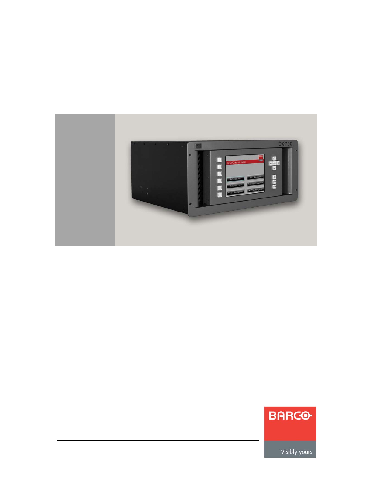
DX-700 Front Panel . . . . . . . . . . . . . . . . . . . . . . . . . . . . . . . . . . . . . . . . . . . . 34
Touch Screen . . . . . . . . . . . . . . . . . . . . . . . . . . . . . . . . . . . . . . . . . . . 36
DX-700 • User’s Guide • Rev 02 7
Page 8

Table of Contents
Touch Screen Conventions. . . . . . . . . . . . . . . . . . . . . . . . . . 36
Test Patterns . . . . . . . . . . . . . . . . . . . . . . . . . . . . . . . . . . . . . . . . . . . . 38
DX-700 Rear Panel . . . . . . . . . . . . . . . . . . . . . . . . . . . . . . . . . . . . . . . . . . . . 40
Input Module . . . . . . . . . . . . . . . . . . . . . . . . . . . . . . . . . . . . . . . . . . . . 41
Input Module Block Diagram . . . . . . . . . . . . . . . . . . . . . . . . . 41
Input Module Description. . . . . . . . . . . . . . . . . . . . . . . . . . . . 41
Output Modules . . . . . . . . . . . . . . . . . . . . . . . . . . . . . . . . . . . . . . . . . . 45
Output Module Description . . . . . . . . . . . . . . . . . . . . . . . . . . 45
Output Module Block Diagrams. . . . . . . . . . . . . . . . . . . . . . . 46
DVI Output Module . . . . . . . . . . . . . . . . . . . . . . . . . . . . . . . . 47
NNI Output Module . . . . . . . . . . . . . . . . . . . . . . . . . . . . . . . . 49
System Module . . . . . . . . . . . . . . . . . . . . . . . . . . . . . . . . . . . . . . . . . . 51
DX-700 Monitor Outputs . . . . . . . . . . . . . . . . . . . . . . . . . . . . 54
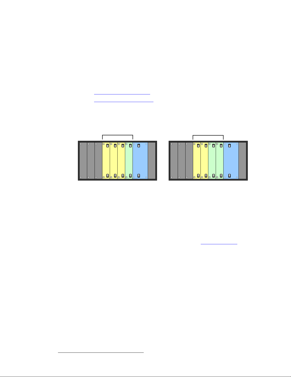
Module Installation and Configuration . . . . . . . . . . . . . . . . . . . . . . . . . . . . . . 55
Module Configuration Rules . . . . . . . . . . . . . . . . . . . . . . . . . . . . . . . . 55
Module Insertion and Extraction . . . . . . . . . . . . . . . . . . . . . . . . . . . . . 57
Module Insertion . . . . . . . . . . . . . . . . . . . . . . . . . . . . . . . . . . 57
Module Extraction . . . . . . . . . . . . . . . . . . . . . . . . . . . . . . . . . 59
Storing Spare Modules . . . . . . . . . . . . . . . . . . . . . . . . . . . . . . . . . . . . 59
`Ü~éíÉê=P fåëí~ää~íáçå =K=K=K=K=K=K=K=K=K=K=K=K=K=K=K=K=K=K=K=K=K=K=K=K=K=K=K=K=K=K=K=K=K=K=K=K=K=K=K=K=K=K=SN
In This Chapter. . . . . . . . . . . . . . . . . . . . . . . . . . . . . . . . . . . . . . . . . . . . . . . . 61
Safety Precautions . . . . . . . . . . . . . . . . . . . . . . . . . . . . . . . . . . . . . . . . . . . . . 62
Unpacking and Inspection . . . . . . . . . . . . . . . . . . . . . . . . . . . . . . . . . . . . . . . 62
Site Preparation . . . . . . . . . . . . . . . . . . . . . . . . . . . . . . . . . . . . . . . . . . . . . . . 62
Cable and Adapter Information. . . . . . . . . . . . . . . . . . . . . . . . . . . . . . . . . . . . 62
Rack-Mount Installation . . . . . . . . . . . . . . . . . . . . . . . . . . . . . . . . . . . . . . . . . 63
Power Installation. . . . . . . . . . . . . . . . . . . . . . . . . . . . . . . . . . . . . . . . . . . . . . 63
Power Cord/Line Voltage Selection. . . . . . . . . . . . . . . . . . . . . . . . . . . 64
Signal Connection . . . . . . . . . . . . . . . . . . . . . . . . . . . . . . . . . . . . . . . . . . . . . 65
Format Connection Table. . . . . . . . . . . . . . . . . . . . . . . . . . . . . . . . . . . . . . . . 68
`Ü~éíÉê=Q léÉê~íáçåK=K=K=K=K=K=K=K=K=K=K=K=K=K=K=K=K=K=K=K=K=K=K=K=K=K=K=K=K=K=K=K=K=K=K=K=K=K=K=K=K=K=K=K=SV
In This Chapter. . . . . . . . . . . . . . . . . . . . . . . . . . . . . . . . . . . . . . . . . . . . . . . . 69
Quick Setup and Operations . . . . . . . . . . . . . . . . . . . . . . . . . . . . . . . . . . . . . 70
Quick Function Reference . . . . . . . . . . . . . . . . . . . . . . . . . . . . . . . . . . . . . . . 72
Controlling the DX-700. . . . . . . . . . . . . . . . . . . . . . . . . . . . . . . . . . . . . . . . . . 76
Power-Up Initialization . . . . . . . . . . . . . . . . . . . . . . . . . . . . . . . . . . . . . . . . . . 77
Using the Home Menu . . . . . . . . . . . . . . . . . . . . . . . . . . . . . . . . . . . . . . . . . . 78
Output Table Description . . . . . . . . . . . . . . . . . . . . . . . . . . . . . . . . . . . . . . . . 79
Using the Setup Wizard . . . . . . . . . . . . . . . . . . . . . . . . . . . . . . . . . . . . . . . . . 80
Setup Wizard Menu Trees. . . . . . . . . . . . . . . . . . . . . . . . . . . . . . . . . . 81
Setup Wizard Operations. . . . . . . . . . . . . . . . . . . . . . . . . . . . . . . . . . . 83
Group Color Scheme. . . . . . . . . . . . . . . . . . . . . . . . . . . . . . . . . . . . . . 92
Using the Input Wizard. . . . . . . . . . . . . . . . . . . . . . . . . . . . . . . . . . . . . . . . . . 93
Input Wizard Menu Tree . . . . . . . . . . . . . . . . . . . . . . . . . . . . . . . . . . . 93
Input Wizard Operations . . . . . . . . . . . . . . . . . . . . . . . . . . . . . . . . . . . 94
Using the Preset Management Menu. . . . . . . . . . . . . . . . . . . . . . . . . . . . . . 103
Preset Management Menu Tree . . . . . . . . . . . . . . . . . . . . . . . . . . . . 103
Preset Management Operations . . . . . . . . . . . . . . . . . . . . . . . . . . . . 104
8 DX-700 • User’s Guide • Rev 02
Page 9

Table of Contents
Recall a Preset . . . . . . . . . . . . . . . . . . . . . . . . . . . . . . . . . . 104
Rename a Preset . . . . . . . . . . . . . . . . . . . . . . . . . . . . . . . . 105
Delete a Preset . . . . . . . . . . . . . . . . . . . . . . . . . . . . . . . . . . 106
Delete All Presets . . . . . . . . . . . . . . . . . . . . . . . . . . . . . . . . 106
Using the Input Management Menu . . . . . . . . . . . . . . . . . . . . . . . . . . . . . . . 107
Input Management Menu Tree . . . . . . . . . . . . . . . . . . . . . . . . . . . . . 107
Input Management Operations Overview . . . . . . . . . . . . . . . . . . . . . 108
Input Management Menu Operations . . . . . . . . . . . . . . . . . . . . . . . . 109
Global Input Management Functions . . . . . . . . . . . . . . . . . 109
Changing Z-Order . . . . . . . . . . . . . . . . . . . . . . . . . . . . . . . . 110
Adjusting Window Settings . . . . . . . . . . . . . . . . . . . . . . . . . 112
Adjusting Viewport Settings. . . . . . . . . . . . . . . . . . . . . . . . . 114
Adjusting Image Processing Parameters . . . . . . . . . . . . . . 115
Adjusting Input Balance. . . . . . . . . . . . . . . . . . . . . . . . . . . . 118
Adjusting Video Effects . . . . . . . . . . . . . . . . . . . . . . . . . . . . 119
Adjusting Color Effects . . . . . . . . . . . . . . . . . . . . . . . . . . . . 120
Adjusting Input Timing. . . . . . . . . . . . . . . . . . . . . . . . . . . . . 121
Saving Input Management Settings . . . . . . . . . . . . . . . . . . 123
Using the Display Management Menu . . . . . . . . . . . . . . . . . . . . . . . . . . . . . 124
Display Management Menu Tree. . . . . . . . . . . . . . . . . . . . . . . . . . . . 125
Display Management Operations . . . . . . . . . . . . . . . . . . . . . . . . . . . 126
Managing LED. . . . . . . . . . . . . . . . . . . . . . . . . . . . . . . . . . . 126
Managing Fiberlink Settings . . . . . . . . . . . . . . . . . . . . . . . . 130
Forcing the Display . . . . . . . . . . . . . . . . . . . . . . . . . . . . . . . 133
Using the DX-700 Management Menu . . . . . . . . . . . . . . . . . . . . . . . . . . . . . 134
DX-700 Management Menu Tree. . . . . . . . . . . . . . . . . . . . . . . . . . . . . . . . . 135
DX-700 Management Menu Operations. . . . . . . . . . . . . . . . . . . . . . . . . . . . 136
Using the DX-700 Status Menu. . . . . . . . . . . . . . . . . . . . . . . . . . . . . 138
Viewing Test Pattern Status . . . . . . . . . . . . . . . . . . . . . . . . 139
Viewing Tile Power Status. . . . . . . . . . . . . . . . . . . . . . . . . . 140
Naming the DX-700 Unit . . . . . . . . . . . . . . . . . . . . . . . . . . . 141
Using the Ethernet Menu. . . . . . . . . . . . . . . . . . . . . . . . . . . . . . . . . . 142
Using the Diagnostics Menu . . . . . . . . . . . . . . . . . . . . . . . . . . . . . . . 143
Using the Front Panel Display Adjustments Menu . . . . . . . . . . . . . . 145
Resetting the System. . . . . . . . . . . . . . . . . . . . . . . . . . . . . . . . . . . . . 145
Rebooting the System. . . . . . . . . . . . . . . . . . . . . . . . . . . . . 145
Performing a Factory Reset . . . . . . . . . . . . . . . . . . . . . . . . 146
Using the Test Pattern Menu. . . . . . . . . . . . . . . . . . . . . . . . . . . . . . . 148
Using the Monitor Output Menu. . . . . . . . . . . . . . . . . . . . . . . . . . . . . 150
Using the EDID Menu . . . . . . . . . . . . . . . . . . . . . . . . . . . . . . . . . . . . 151
Understanding Genlock Options . . . . . . . . . . . . . . . . . . . . . . . . . . . . 153
Setting Genlock Using the Bank Sync Menu. . . . . . . . . . . . 153
Setting the Master Sync Source . . . . . . . . . . . . . . . . . . . . . 156
Using the Expert Menu . . . . . . . . . . . . . . . . . . . . . . . . . . . . . . . . . . . 158
Pre-selecting the Delay Mode . . . . . . . . . . . . . . . . . . . . . . 159
Refreshing the Canvas Size . . . . . . . . . . . . . . . . . . . . . . . . 160
Setting Output Timing . . . . . . . . . . . . . . . . . . . . . . . . . . . . . 161
Saving DX-700 Management Settings. . . . . . . . . . . . . . . . . . . . . . . . 164
Front Panel Lockout . . . . . . . . . . . . . . . . . . . . . . . . . . . . . . . . . . . . . . . . . . . 165
DX-700 • User’s Guide • Rev 02 9
Page 10

Table of Contents
`Ü~éíÉê=R réÖê~ÇáåÖ=cáêãï~êÉ=K=K=K=K=K=K=K=K=K=K=K=K=K=K=K=K=K=K=K=K=K=K=K=K=K=K=K=K=K=K=K=KNST
In This Chapter. . . . . . . . . . . . . . . . . . . . . . . . . . . . . . . . . . . . . . . . . . . . . . . 167
Firmware Upgrade Overview . . . . . . . . . . . . . . . . . . . . . . . . . . . . . . . . . . . . 168
Hardware Requirements. . . . . . . . . . . . . . . . . . . . . . . . . . . . . . . . . . . . . . . . 168
Computer and Download Requirements . . . . . . . . . . . . . . . . . . . . . . . . . . . 168
Upgrading Firmware. . . . . . . . . . . . . . . . . . . . . . . . . . . . . . . . . . . . . . . . . . . 168
^ййЙеЗбс=^= pйЙЕбСбЕ~нбзелK=K=K=K=K=K=K=K=K=K=K=K=K=K=K=K=K=K=K=K=K=K=K=K=K=K=K=K=K=K=K=K=K=K=K=K=K=K=KNTN
In This Appendix. . . . . . . . . . . . . . . . . . . . . . . . . . . . . . . . . . . . . . . . . . . . . . 171
Input Specifications . . . . . . . . . . . . . . . . . . . . . . . . . . . . . . . . . . . . . . . . . . . 172
Output Specifications . . . . . . . . . . . . . . . . . . . . . . . . . . . . . . . . . . . . . . . . . . 174
DVI Output Module . . . . . . . . . . . . . . . . . . . . . . . . . . . . . . . . . . . . . . 174
NNI Output Module . . . . . . . . . . . . . . . . . . . . . . . . . . . . . . . . . . . . . . 175
Genlock Specifications. . . . . . . . . . . . . . . . . . . . . . . . . . . . . . . . . . . . . . . . . 175
Physical and Electrical Specifications . . . . . . . . . . . . . . . . . . . . . . . . . . . . . 176
Communications Specifications . . . . . . . . . . . . . . . . . . . . . . . . . . . . . . . . . . 177
Agency Specifications . . . . . . . . . . . . . . . . . . . . . . . . . . . . . . . . . . . . . . . . . 177
Delay Specifications. . . . . . . . . . . . . . . . . . . . . . . . . . . . . . . . . . . . . . . . . . . 178
Delay Table 50 Hz. . . . . . . . . . . . . . . . . . . . . . . . . . . . . . . . . . . . . . . 178
Delay Table 60 Hz. . . . . . . . . . . . . . . . . . . . . . . . . . . . . . . . . . . . . . . 178
Pinouts . . . . . . . . . . . . . . . . . . . . . . . . . . . . . . . . . . . . . . . . . . . . . . . . . . . . . 179
Analog 15-pin D Connector . . . . . . . . . . . . . . . . . . . . . . . . . . . . . . . . 179
DVI-I Connector Pinouts . . . . . . . . . . . . . . . . . . . . . . . . . . . . . . . . . . 180
Standard DVI-I Connector. . . . . . . . . . . . . . . . . . . . . . . . . . 181
Proprietary DVI-I Connector . . . . . . . . . . . . . . . . . . . . . . . . 182
Ethernet Connector . . . . . . . . . . . . . . . . . . . . . . . . . . . . . . . . . . . . . . 183
Diagnostic Connector . . . . . . . . . . . . . . . . . . . . . . . . . . . . . . . . . . . . 183
DMX Connector . . . . . . . . . . . . . . . . . . . . . . . . . . . . . . . . . . . . . . . . . 184
NNI Connector. . . . . . . . . . . . . . . . . . . . . . . . . . . . . . . . . . . . . . . . . . 184
^ййЙеЗбс=_= oЙгзнЙ=`зенкзд=mкзнзЕздK=K=K=K=K=K=K=K=K=K=K=K=K=K=K=K=K=K=K=K=K=K=K=K=K=K=K=K=KNUR
In This Appendix. . . . . . . . . . . . . . . . . . . . . . . . . . . . . . . . . . . . . . . . . . . . . . 185
Remote Commands . . . . . . . . . . . . . . . . . . . . . . . . . . . . . . . . . . . . . . . . . . . 186
Command Structure. . . . . . . . . . . . . . . . . . . . . . . . . . . . . . . . . . . . . . 186
Overview . . . . . . . . . . . . . . . . . . . . . . . . . . . . . . . . . . . . . . . 186
Update/Set Command Format . . . . . . . . . . . . . . . . . . . . . . 186
Query Command Format. . . . . . . . . . . . . . . . . . . . . . . . . . . 187
DX-700 Response to Commands . . . . . . . . . . . . . . . . . . . . 187
Important Notes. . . . . . . . . . . . . . . . . . . . . . . . . . . . . . . . . . 189
Establishing Communications . . . . . . . . . . . . . . . . . . . . . . . . . . . . . . 189
DX-700 Remote Command Table . . . . . . . . . . . . . . . . . . . . . . . . . . . . . . . . 190
DX-700 Remote Command List . . . . . . . . . . . . . . . . . . . . . . . . . . . . . . . . . . 191
Output LED Commands. . . . . . . . . . . . . . . . . . . . . . . . . . . . . . . . . . . 191
SCRPWR . . . . . . . . . . . . . . . . . . . . . . . . . . . . . . . . . . . . . . 191
WALLCONTR . . . . . . . . . . . . . . . . . . . . . . . . . . . . . . . . . . . 191
WALLGAMMA. . . . . . . . . . . . . . . . . . . . . . . . . . . . . . . . . . . 192
WALLOSD. . . . . . . . . . . . . . . . . . . . . . . . . . . . . . . . . . . . . . 193
WALLOSDLIST?. . . . . . . . . . . . . . . . . . . . . . . . . . . . . . . . . 194
10 DX-700 • User’s Guide • Rev 02
Page 11

Table of Contents
Output Fiberlink Commands . . . . . . . . . . . . . . . . . . . . . . . . . . . . . . . 194
FIBERRXPWR . . . . . . . . . . . . . . . . . . . . . . . . . . . . . . . . . . 194
FIBERKEYREF . . . . . . . . . . . . . . . . . . . . . . . . . . . . . . . . . . 195
FIBERFILTER . . . . . . . . . . . . . . . . . . . . . . . . . . . . . . . . . . . 195
FIBERSN. . . . . . . . . . . . . . . . . . . . . . . . . . . . . . . . . . . . . . . 196
FIBERPCB . . . . . . . . . . . . . . . . . . . . . . . . . . . . . . . . . . . . . 196
FIBERSOFT . . . . . . . . . . . . . . . . . . . . . . . . . . . . . . . . . . . . 197
FIBERFIRM. . . . . . . . . . . . . . . . . . . . . . . . . . . . . . . . . . . . . 197
FIBERRTIME. . . . . . . . . . . . . . . . . . . . . . . . . . . . . . . . . . . . 197
Monitor Output Commands . . . . . . . . . . . . . . . . . . . . . . . . . . . . . . . . 198
MORES. . . . . . . . . . . . . . . . . . . . . . . . . . . . . . . . . . . . . . . . 198
MSAVE . . . . . . . . . . . . . . . . . . . . . . . . . . . . . . . . . . . . . . . . 198
MOBANK. . . . . . . . . . . . . . . . . . . . . . . . . . . . . . . . . . . . . . . 198
Preset Commands. . . . . . . . . . . . . . . . . . . . . . . . . . . . . . . . . . . . . . . 199
PSCALL. . . . . . . . . . . . . . . . . . . . . . . . . . . . . . . . . . . . . . . . 199
PSNUM . . . . . . . . . . . . . . . . . . . . . . . . . . . . . . . . . . . . . . . . 199
PSPRN . . . . . . . . . . . . . . . . . . . . . . . . . . . . . . . . . . . . . . . . 199
PTRANS . . . . . . . . . . . . . . . . . . . . . . . . . . . . . . . . . . . . . . . 200
Miscellaneous Commands. . . . . . . . . . . . . . . . . . . . . . . . . . . . . . . . . 200
DISCOVERY. . . . . . . . . . . . . . . . . . . . . . . . . . . . . . . . . . . . 200
WHOAREYOU . . . . . . . . . . . . . . . . . . . . . . . . . . . . . . . . . . 201
CLOSE . . . . . . . . . . . . . . . . . . . . . . . . . . . . . . . . . . . . . . . . 201
BANK. . . . . . . . . . . . . . . . . . . . . . . . . . . . . . . . . . . . . . . . . . 201
^ййЙеЗбс=`= `зен~Ен=fеСзкг~нбзе=K=K=K=K=K=K=K=K=K=K=K=K=K=K=K=K=K=K=K=K=K=K=K=K=K=K=K=K=K=K=K=K=KOMP
In This Appendix. . . . . . . . . . . . . . . . . . . . . . . . . . . . . . . . . . . . . . . . . . . . . . 203
Warranty. . . . . . . . . . . . . . . . . . . . . . . . . . . . . . . . . . . . . . . . . . . . . . . . . . . . 203
Customer Service Portal. . . . . . . . . . . . . . . . . . . . . . . . . . . . . . . . . . . . . . . . 203
Return Material Authorization (RMA) . . . . . . . . . . . . . . . . . . . . . . . . . . . . . . 204
Contact Information . . . . . . . . . . . . . . . . . . . . . . . . . . . . . . . . . . . . . . . . . . . 204
^ййЙеЗбс=a= cбДЙкдбев=kkf=fелн~дд~нбзеK=K=K=K=K=K=K=K=K=K=K=K=K=K=K=K=K=K=K=K=K=K=K=K=K=K=K=K=KOMR
In This Appendix. . . . . . . . . . . . . . . . . . . . . . . . . . . . . . . . . . . . . . . . . . . . . . 205
Overview. . . . . . . . . . . . . . . . . . . . . . . . . . . . . . . . . . . . . . . . . . . . . . . . . . . . 206
Fiberlink NNI Hardware . . . . . . . . . . . . . . . . . . . . . . . . . . . . . . . . . . . . . . . . 208
Fiberlink NNI Transmitter. . . . . . . . . . . . . . . . . . . . . . . . . . . . . . . . . . 208
Fiberlink NNI Receiver. . . . . . . . . . . . . . . . . . . . . . . . . . . . . . . . . . . . 210
LED Error Conditions. . . . . . . . . . . . . . . . . . . . . . . . . . . . . . . . . . . . . 211
Installation . . . . . . . . . . . . . . . . . . . . . . . . . . . . . . . . . . . . . . . . . . . . . . . . . . 212
Unpacking and Inspection . . . . . . . . . . . . . . . . . . . . . . . . . . . . . . . . . 212
Site Preparation. . . . . . . . . . . . . . . . . . . . . . . . . . . . . . . . . . . . . . . . . 212
Cable and Adapter Information . . . . . . . . . . . . . . . . . . . . . . . . . . . . . 213
Securing the Dust Cap on the Fiber Optic Cable. . . . . . . . . . . . . . . . 213
Installing the Fiberlink NNI Modules . . . . . . . . . . . . . . . . . . . . . . . . . 214
Signal Connection . . . . . . . . . . . . . . . . . . . . . . . . . . . . . . . . . . . . . . . 214
Power Handling . . . . . . . . . . . . . . . . . . . . . . . . . . . . . . . . . . . . . . . . . . . . . . 215
Proper Fiber Optic Cable Maintenance . . . . . . . . . . . . . . . . . . . . . . . . . . . . 216
Laser Safety . . . . . . . . . . . . . . . . . . . . . . . . . . . . . . . . . . . . . . . . . . . . . . . . . 217
Technical Specifications. . . . . . . . . . . . . . . . . . . . . . . . . . . . . . . . . . . . . . . . 218
DX-700 • User’s Guide • Rev 02 11
Page 12

Table of Contents
fåÇÉñ =K=K=K=K=K=K=K=K=K=K=K=K=K=K=K=K=K=K=K=K=K=K=K=K=K=K=K=K=K=K=K=K=K=K=K=K=K=K=K=K=K=K=K=K=K=K=K=K=K=K=K=KONV
12 DX-700 • User’s Guide • Rev 02
Page 13

NK==fенкзЗмЕнбзе
få=qÜáë=`Ü~éíÉê
This chapter is designed to introduce you to the DX-700 User’s Guide. Areas to be
covered are:
• Firmware Version
• Chapter Structure
• How to Use This Guide
• Conventions
• About the DX-700
• Connectivity Diagrams
• Application Questions
DX-700 • User’s Guide • Rev 02 13
Page 14

NK==fенкзЗмЕнбзе
Firmware Version
cбкгп~кЙ=sЙклбзе
This version of the DX-700 User’s Guide is based on firmware version 2.30.
`Ь~йнЙк=pнкмЕнмкЙ
The following chapters provide instructions for all aspects of DX-700 operations:
• Chapter 1, “Introduction” provides a system overview, a list of features, and a
system connectivity diagram.
• Chapter 2, “Hardware Orientation” on page 33 provides detailed diagrams of the
DX-700’s front and rear panels.
• Chapter 3, “Installation” on page 61 provides comprehensive system installation
instructions.
• Chapter 4, “Operation” on page 69 provides menu trees, plus comprehensive
DX-700 operating instructions.
• Chapter 5, “Upgrading Firmware” on page 167 outlines procedures for
upgrading DX-700 firmware.
• Appendix A, “Specifications” on page 171 lists the DX-700’s specifications.
• Appendix B, “Remote Control Protocol” on page 185 provides information
regarding remote control commands and protocol.
• Appendix C, “Contact Information” on page 203 lists important Barco contact,
RMA, warranty and technical support details.
• Appendix D, “Fiberlink NNI Installati on ” on page 205 provides setup and
operating instructions for the optional Fiberlink NNI Multi-mode Transmitter and
Receiver.
14 DX-700 • User’s Guide • Rev 02
Page 15
eçï=íç=rëÉ=qÜáë=dìáÇÉ
This section provides important tips for streamlining the use of this User’s Guide in its
electronic PDF form.
k~îáÖ~íáåÖ
Use Acrobat Reader’s “bookmarks” to navigate to the desired location. All chapter files
have the same bookmark structure for instant navigation to any section. Please note:
• Extensive hyperlinks are provided within the chapters.
• Use Acrobat’s “Go to Previous View” and “Return to Next View” buttons to trace
your complete navigational path.
• Use the “Previous Page” and “Next Page” buttons to go to the previous or next
page within a file.
• Use Acrobat’s extensive search capabilities, such as the “Find” tool and “Search
Index” tool to perform comprehensive searches as required.
NK==fенкзЗмЕнбзе
How to Use This Guide
q~ДдЙ=зС=`зенЙенл=~еЗ=fеЗЙс
Use the Table of Contents bookmarks to navigate a desired topic. Click any item to
instantly jump to that section of the guide. You can also use the Index to jump to specific
topics within a chapter. Each page number in the Index is a hyperlink.
`зеоЙенбзел=
The following conventions are used throughout this guide:
• The symbol denotes an operations procedure.
• The symbol S denotes an example.
• Entries written in bold-face capital letters denote physical buttons or connectors.
S Press ENTER to ...
• Button labels on the Touch Screen are shown in bold letters between braces.
S Press {Input Wizard} to …
• A sequence of steps is represented by the menu names, separated by arrows (>).
S Press {DX-700 Management} > {Test Patterns} > {Bank 2}
... indicates the following sequence:
a. From the Home Menu, press {DX-700 Management}.
b. On the DX-700 Management Menu, press {Test Patterns}.
c. On the Output Selection Menu, select {Bank 2}.
DX-700 • User’s Guide • Rev 02 15
Page 16

NK==fенкзЗмЕнбзе
About the DX-700
^Äçìí=íÜÉ=auJTMM
The following topics are discussed in this section:
• Overview
• Basic Features
• New Features
• Theory of Operation
• Understanding Banks
• Grouping Outputs
• DX-700 Stacking
• DX-700 Scaling
• DX-700 Video Processing Delay
• DX-700 Input Identification
• DX-700 Input Switching
• Firmware Upgrades
• Application Questions
lоЙкобЙп
The DX-700 is a multi-window video processor designed as a versatile front-end to all
Barco LED products.
• Current LED products such as MiPIX, MiTRIX, MiSTRIP, DLite, OLite, SLite and
ILite are supported via the DVI LED interface on the DVI output module.
• Next generation LED products such as NX-4 are supported via the NNI LED
interface on the DX-700’s NNI output module.
Image processing and LED wall configuration and control functions are adjusted from the
DX-700 front panel, or from Barco’s Director Toolset. Refer to the “Basic Features
section on page 17 for additional details.
Important
Please note:
Director Toolset version 2.0 or later is required.
• To ensure trouble-free installation and operation of your DX-700, please follow all
procedures in the following two sections:
~ Chapter 3, “Installation” on page 61.
~ Chapter 4, “Operation” on page 69.
• Should you have any questions regarding the installation or operation of the
DX-700, please consult with the factory. Refer to Appendix C, “Contact
Information” on page 203 for contact details.
”
16 DX-700 • User’s Guide • Rev 02
Page 17

_~лбЕ=cЙ~нмкЙл
Basic features of the DX-700=system are listed below:
• System Features
~ Basic configuration is performed using front panel controls on the DX-
700. Advanced configuration is performed using Director Toolset.
~ Seven rear panel slots are provided for input and output modules. All
modules are fully shielded and field-installable.
~ Input and output modules can be configured into “banks” of functionality
— essentially, independent video processors capable of driving one or
more LED walls.
~ The System Module provides Ethernet, diagnostic, DMX and genlock
ports. Analog and digital monitor outputs are provided. DX-700 can be
genlocked to an external reference, to a selected input, or set to free-run.
~ Rack-mountable chassis (5RU).
• Input Features
~ Input modules provide “universal” connections for DVI (RGB or YCbCr),
Dual-DVI (RGB), Component Analog (RGB or YPbPr), NTSC/PAL,
CVBS or Y/C, SD-SDI, HD-SDI, and Dual HD-SDI formats. Multiple
input modules can be assigned to a bank.
~ All inputs except DVI provide a minimum 10-bit color depth, in either
4:4:4 or 4:2:2 format. An advanced motion-adaptive de-interlacer
converts interlaced or progressive segmented frame (PSF) inputs to
progressive format.
~ Processing is performed with a 12-bit minimum color depth.
~ Input balancing can be applied to any input.
• Output Features
~ Output modules are available in two formats: DVI (for legacy Barco tiles),
and NNI (for next-generation Barco tiles).
~ Each output module has three output connections that can be driven
independently or “grouped.” When there are two output modules in a
bank, all six output connections can be driven independently or grouped.
~ Up to two output modules can be included in a bank. Refer to the
“Understanding Banks” section on page 24 fo r details.
~ Video layers can be alpha-blended (e.g., assigned an attribute of
invisible, opaque, or any level in between), regardless of layer priority.
~ Color-keying is supported, using any input module as a key source.
~ A variety of digital video effects are supported, including freeze, strobe,
and linear color transformations (e.g., monochrome and inverted video).
• Operational Modes
~ Setup and Input wizards
~ Preset save and recall
~ Input, display and system management
~ Input source adjustments (saturation, input balance, sharpness, etc.)
NK==fенкзЗмЕнбзе
About the DX-700
DX-700 • User’s Guide • Rev 02 17
Page 18

NK==fенкзЗмЕнбзе
About the DX-700
kЙп=cЙ~нмкЙл
The following topics are discussed in this section:
cбкгп~кЙ=sЙклбзе=OKNM=cЙ~нмкЙл
The following features and functions were implemented in firmware version 2.10:
• Firmware Version 2.10 Features
• Firmware Version 2.30 Features
• External Stacking — This mode enables multiple DX-700 units to be joined
together to increase the overall canvas size, either horizontally or vertically. For
details, refer to the “E
xternal Stacking” section on page 26.
• Cross-bank Stacking — This mode enables multiple banks to be connected
together within a single DX-700 chassis, using the expansion links on an input
module. Cross-bank stacking supports synchronizing inputs in multiple banks.
For more information, refer to the “Cross-bank Stacking
” section on page 26.
• Input Formats — The following additional input formats are now detected:
~ 1920 x 1080pSF @ 30 and 29.97
~ 1280 x 720 @ 60
~ 1280 x 800 @ 60
~ 1360 x 768 @ 60
~ 1440 x 900 @ 60, 75 and 85
~ 1680 x 1050 @ 60
• Autosave — a check box has been added on the Expert Menu to turn the
Autosave mode on or off. In Chapter 4, refer to the “Using the Expert Menu”
section on page 15 8.
• Tiles and Modules — Support has been added for the following LED tiles and
modules:
~ TF-20
~ T-20
~ I6 BK
• Apply Over Black — On the Preset Recall Menu, an Apply over Black
checkbox has been added. In Chapter 4, refer to the “Pre set Management
Operations” section on page 104.
• Z-Order Support — On the Input Management Menu, support has been added
for Z-Order. In Chapter 4, refer to the “I
section on page 10 9.
nput Management Menu Operations”
• Luma Keying — The luma keying function has been implemented for control by
Director Toolset only. Refer to the “Director Toolset User’s Guide.”
• Input Sharpness — On Image Processing Tab 1 (I.P. 1 ), a sharpness
adjustment has been implemented. In Chapter 4, refer to the “Adjusting Image
Processing Parameters” section on page 115.
• Cable Equalization — On Image Processing Tab 1 (I.P. 1), a cable equalization
adjustment has been implemented. In Chapter 4, refer to the “Adjusting Image
Processing Parameters” section on page 115.
• Soft Reset — Users can now perform both Factory and Soft system resets. In
Chapter 4, refer to the “R
esetting the System” section on page 145 for details.
18 DX-700 • User’s Guide • Rev 02
Page 19

NK==fенкзЗмЕнбзе
About the DX-700
• Output Timing — Controls for output timing have been added to the Expert
Menu. In Chapter 4, refer to the “Using the Expert Menu” section on page 158.
• A Minimum Delay Mode has been added. Refer to the “DX-700 Video
Processing Delay” section on page 28 for details.
• Restore Scaling — In the Output Display Menu, buttons have been added to
allow users to reset tile H/V scaling parameters. In Chapter 4, refer to the
“Display Management Operations
• PTRANS Command — This remote command allows users to select the Preset
transition type. In Appendix B, refer to the “Remote Commands
page 186 for details.
cбкгп~кЙ=sЙклбзе=OKPM=cЙ~нмкЙл
The following features have been implemented in firmware version 2.30:
• A Reduced Delay Mode has been added, which provides a significant reduction
in video processing delay. Refer to the “DX-700 V ideo Processing Delay”
section on page 28 for details.
• Tiles and Modules — support has been added for the following LED tiles and
modules:
~ T-16 tiles
~ TF-16 tiles
~ FLX series modules
” section on page 126 for details.
” section on
DX-700 • User’s Guide • Rev 02 19
Page 20
NK==fенкзЗмЕнбзе
About the DX-700
qЬЙзку=зС=lйЙк~нбзе
The following topics are discussed in this section:
fенкзЗмЕнбзе=нз=нЬЙ=`~ео~л
The DX-700 processor enables you to set up video walls, and define input sources and
LED outputs with precision. The DX-700's input and output modules are configured into
"banks," consisting of one or more input modules, and either one or two output modules.
Each bank enables you to combine inputs and outputs into independent video processors,
capable of driving one or more LED walls. Refer to the “Understanding Banks
page 24 for additional information on banks.
The DX-700's overall workspace is called the "canvas," the region in which you configure
inputs and outputs. Each bank provides a maximum canvas size of 2048 x 1080 pixels (or
1080 x 2048 pixels). By default, the canvas appears as a black background in both th e
LED and monitor outputs.
• Introduction to the Canvas
• Introduction to the Wizards
• Sample DVI Output Module Configurations
• Sample NNI Output Module Configurations
” section on
1080
pixels
2048 pixels
2048
pixels
1080
pixels
Figure 1-1. DX-700 Canvas Examples
Within the canvas, you can place up to six output regions, provided that the selected bank
includes two output modules. For input flexibility, you can scale input sources to fit LED
outputs precisely, or you can select just a portion of an input to fit a wall.
Output modules are extremely versatile:
• Each module’s three outputs can be driven independently — each connected to a
different type of LED wall.
• Two or more outputs can be grouped together, in order to form a larger overall
video wall comprised of the same type of tiles.
20 DX-700 • User’s Guide • Rev 02
Page 21

NK==fенкзЗмЕнбзе
About the DX-700
Please note:
• When using DVI output modules, the maximum output resolution (e.g., 2048 x
1080) is achieved with two DVI output modules. With NNI output modules, only
one module is required.
• In a dual-bank system, two canvases are available for use — but each bank does
not have knowledge of the other bank’s configuration.
fенкзЗмЕнбзе=нз=нЬЙ=tбт~кЗл
The DX-700 includes two special “wizards” that facilitate the overall setup:
• When you run the Setup Wizard, the DX-700 detects all tiles that are connected
to each output module, and then takes you through the output setup and grouping
steps. Once each output is set up, the DX-700 places its rectangular “pixel
region” on the canvas. At the conclusion of the Setup Wizard, you can
automatically enter the Input Wizard.
• When you run the Input Wizard, the DX-700 asks you to choose an output,
choose an input module, and then choose a specific input. Next, the system leads
you through the setup and scaling steps. When complete, you will store a
“preset,” and then repeat the procedure for all remaining inputs.
Note
If the Setup Wizard is used, the placement of output “regions” on the canvas is automatic.
If Director Toolset is used, outputs can be placed anywhere on the canvas. The DX-700
starts output placement at coordinate H0, V0, and continues by placing each subsequent
region based on the previous output’s horizontal width and vertical size — without
overlapping, and without leaving gaps. If the DX-700 can’t place output regions adjacent
horizontally, it attempts to place them vertically. This canvas placement is visible on the
monitor output.
Important
Output modules have a limited pixel capacity per output, as outlined in the following two
sections.
A DX-700 “preset” is a non-volatile file that stores bankspecific configurations for all inputs and outputs, including
LED wall settings.
If the DX-700 determines that the canvas’ available pixel
space will be exceeded, you are asked to use the Director
Toolset for further configuration. Similarly, if “creative” LEDs
are used (such as MiTRIX and MiSTRIP), you will also be
asked to use the Director Toolset.
p~гйдЙ=asf=lмнймн=jзЗмдЙ=`зеСбЦмк~нбзел
For DVI output modules, each output is limited to the following parameters:
• A rectangular shape
• Up to 480,000 pixels
• Any orientation up to 2048 pixels on a side
DX-700 • User’s Guide • Rev 02 21
Page 22
NK==fенкзЗмЕнбзе
About the DX-700
Using one DVI output module (3 outputs), the following sample configurations are possible,
without exceeding pixel capacity:
• Example 1: 3 x (600 x 800 pixels)
• Example 2: 3 x (230 x 2048 pixels)
2048 pixels
1080
pixels
1080
pixels
Module 1
Output 1
600 x 800
Module 1
Output 2
600 x 800
Module 1, Output 1
230 x 2048
Module 1, Output 3
230 x 2048
Module 1, Output 3
230 x 2048
Module 1
Output 3
600 x 800
1
2
Figure 1-2. Sample DVI canvases that use one output module
In the following illustration, using two DVI output modules (with 6 available outputs), the
following sample configurations are possible without exceeding pixel capacity:
• Example 1: 4 x different resolutions and aspect ratios
• Example 2: 6 x (340 x 1080 pixels)
2048 pixels
Module 2
Output 1
600 x 250
Output 3
500 x 700
1
1080
pixels
Module 1
Output 1
600 x 500
Module 1,
340 x 900
Module 1, Output 2
1080
pixels
340 x 1080
340 x 1080
340 x 1080
340 x 1080
340 x 1080
Module 1, Output 1
Module 1, Output 2
Module 1, Output 3
Module 2, Output 1
Module 2, Output 2
2
340 x 1080
Module 2, Output 3
Figure 1-3. Sample DVI canvases that use two output modules
Note
Remember that LED walls do not have to be the same size
and aspect ratio, and that the outputs can be used individually
or grouped to form larger walls.
22 DX-700 • User’s Guide • Rev 02
Page 23
NK==fенкзЗмЕнбзе
About the DX-700
p~гйдЙ=kkf=lмнймн=jзЗмдЙ=`зеСбЦмк~нбзел
For NNI output modules, each output is limited to the following parameters:
• A rectangular shape
• Up to 786,432 pixels
• Any orientation up to 2048 pixels on a side
Using one NNI output module (3 outputs), the following sample configuration is possible,
without exceeding pixel capacity:
2048 pixels
Module 1
1080
pixels
Figure 1-4. Sample canvas using one NNI output module
Please note the following important points regarding the canvas:
Output 1
1024 x 768
Module 1
Output 2
1024 x 768
• For both NNI and DVI output modules, if smaller tile arrays are used, more output
regions can be placed on the canvas — up to the maximum of 6 outputs.
• You cannot mix tile categories (DVI interface and NNI interface) within a bank.
• If your specific tile configuration exceeds the capacity of DX-700’s wizards, you
must use the
Toolset User’s Guide.”
Director Toolset. For more information, refer to the “Director
DX-700 • User’s Guide • Rev 02 23
Page 24
NK==fенкзЗмЕнбзе
About the DX-700
rеЗЙклн~еЗбеЦ=_~евл
DX-700 supports a wide number of flexible system configurations. Input and output
modules are installed in “banks,” consisting of one or more input modules and either one or
two output modules (with two being the maximum allowed in a bank). By definition, a
is a way of combining inputs and outputs into independent video processors that are
capable of driving one or more LED walls.
A single DX-700
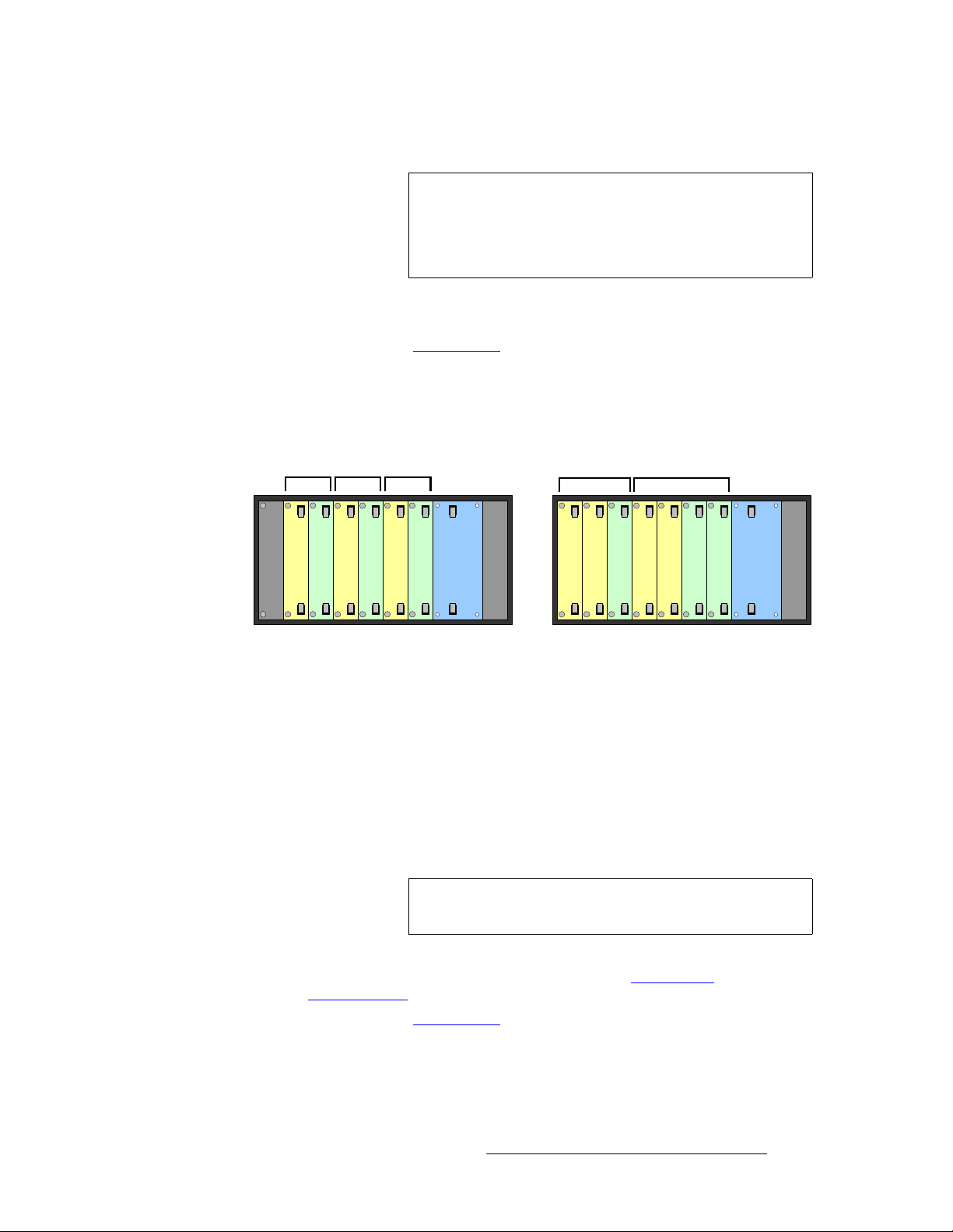
pбеЦдЙ=_~ев=`зеСбЦмк~нбзел
The figure below illustrates two examples of single bank configurations:
bank
=supports both single and multi-bank configurations, as detailed below.
• Single Bank Configurations
• Multiple Bank Configurations
Bank 1
Input
Input
Blank
Blank
Blank
Multi-input, single output
Figure 1-5. Single bank configuration examples
Please note the following points regarding single bank configurations:
Input
Output
Power
System
Blank
Blank
Bank 1
Input
Input
Blank
Multi-input, dual output
Output
Output
Power
System
• A single bank has a maximum “canvas” size of 2048 x 1080 pixels (or 1080 x
2048 pixels). This overall region can be divided as required betw een three
outputs (using one output module), or six outputs (using two output modules).
• From two to six physical outputs can be “grouped” electronically to form a larger
“logical” output. This grouping enables you to control a larger LED display —
larger than is possible with a single output. Refe r to the “
section on page 26 of this chapter for more information.
Grouping Outputs”
• Based on seven slots for input and output modules, you can use up to six input
modules in a bank with one output module, or up to five input modules in a bank
with two output modules.
Numerous output combinations are possible within a single bank — because each output
can be driven independently or grouped with other outputs. Remember that a maximum of
two output modules can be included in a bank.
• A single output module can drive up to three attached displays from any portion of
the canvas.
• The LED displays driven by the outputs can be configured with any type of tile
within a single tile category. For example:
~ All legacy tiles used: Output 1 (MiPIX), Output 2 (DLite 7), Output 3
(OLite 612)
24 DX-700 • User’s Guide • Rev 02
Page 25
~ All new tiles used: Outputs 1, 2 and 3 (NX-4)
NK==fенкзЗмЕнбзе
About the DX-700
Important
You cannot mix tile categories within a bank. Thus, the
following combination is
not allowed:
• Output Module 1: MiPIX, DLite 7
• Output Module 2: NX-4
• Remember that output “grouping” is supported within a single bank. This means
that each output can be configured to drive a portion of a larger overall di splay.
In Chapter 2, refer to the “
Input Module” section on page 41 for important information on
the configuration of modules and banks.
jмднбйдЙ=_~ев=`зеСбЦмк~нбзел
The figure below illustrates two examples of multi-bank configurations:
Bank 1
Blank
Bank 2 Bank 3
Input
Input
Output
Output
Triple bank, single input
Bank 1
Input
Output
System
Power
Input
Input
Bank 2
Input
Output
Dual bank, multi-input
Input
Output
Output
System
Power
Figure 1-6. Multi-bank configuration examples
Please note the following points regarding multi-bank DX-700 configurations:
• Each bank in a multi-bank configuration has a maximum canvas size of 2048 x
1080 pixels. Each canvas can be divided as required between three outputs
(using one output module), or six outputs (using two output modules).
• Each input module within a bank can add its video image to that bank's canvas.
• A single output module within a bank can drive one or more attached displays
from any portion of that bank’s canvas. The displays can be any type of tile within
the “new” or “legacy” categories, but you cannot mix tile categories within a bank.
Note
One bank can be assigned to drive NNI interface tiles, while
another bank can be assigned to drive DVI interface tiles.
• Numerous output combinations are possible within a multi-bank system, similar to
those combinations described and illustrated in the “
Configurations” section on page 24.
In Chapter 2, refer to the “
Input Module” section on page 41 for important information on
the configuration of modules and banks.
Single Bank
DX-700 • User’s Guide • Rev 02 25
Page 26

NK==fенкзЗмЕнбзе
About the DX-700
dкзмйбеЦ=lмнймнл
Within a single bank of a DX-700, you can group up to six physical outputs in a bank to
form a larger logical output display. This grouping enables you to control an LED display
that is larger than can be controlled with a single output.
The
you have set up two or more outputs in a single bank. In Chapter 4, refer to the “
Setup Wizard” section on page 80 for more information about grouping outputs.
auJTMM=pн~ЕвбеЦ
Stacking is the practice of increasing the canvas size in order to display video output across
a larger area, either horizontally or vertically. The DX-700 provides two types of stacking:
The following topics are discussed in this section:
Display Layout Menu within the Setup Wizard is used to implement grouping, after
Using the
• “External” stacking occurs across DX-700 machines. In this configuration, you
create physical connections across two or more DX-700s. Each machine’s inputs
are made available to the next DX-700(s). A "lock" signal must also be sent from
the "master" frame to all "slave" frames in the stack.
• “Cross-bank” stacking occurs across banks in a single DX-700 unit. In this
type of stacking, one bank’s input connectors are linked to the corresponding input
connectors of another bank. This function allows a single input source to be
visible on the canvas of both banks.
• External Stacking
• Cross-bank Stacking
• Stacking and Video Delay
• Expansion Links
bснЙке~д=pн~ЕвбеЦ
The external stacking function enables multiple DX-700 units to be joined together in order
to increase the overall canvas size — either horizontally or vertically. When working in this
mode, all DX-700 units must have the same configuration, as follows:
• Video sources are all connected to input modules of the “master” DX-700.
• On each of the master’s input modules, the Expansion Out DVI port is connected
to the
DVI Input port on the first slave unit’s input modules. Similarly, the first
slave connects to the second, etc.
• A Sync output on the master unit’s System module allows slave units to genlock.
This signal can also be daisy-chained to several DX-700
Note
Use Director Toolset to set up external stacking.
=units.
`кзллJД~ев=pн~ЕвбеЦ
The expansion links on a DX-700 input module can be used to connect multiple banks
together within a single DX-700 chassis — a feature called cross-bank stacking. The
advantage is that a single input can be displayed across multiple banks.
For cross-bank stacking, the linked banks must all have the same configuration, as follows:
• Video sources are all connected to the first bank’s input modules.
26 DX-700 • User’s Guide • Rev 02
Page 27

NK==fенкзЗмЕнбзе
About the DX-700
• For input modules in the first bank, expansion link cables from the Expansion Out
DVI ports are connected to the second bank’s DVI inputs.
Note
Use Director Toolset to set up cross-bank stacking.
pн~ЕвбеЦ=~еЗ=sбЗЙз=aЙд~у
An additional benefit of both cross-bank and external stacking is that a system
configuration requiring vertical output stacking (in a single bank) can be built wi thout
incurring video delay.
S Consider a configuration that uses two outputs within a bank, each driving a
wall section, and the two wall sections comprise the overall image. If the two
sections are oriented horizontally, there is no additional delay. If the two
sections are vertically oriented, extra delay is added. Here, moving to either
a cross-bank or external stacking configuration may alleviate the extra delay.
bсй~елбзе=iбевл
When multiple DX-700 units (or multiple DX-700 banks) are linked to create a final output
image that’s larger than is possible using only one unit, all DX-700 units must process each
input
identically. This guarantees that there are no discontinuities in color balance, sample
phase and other parameters at boundaries between each DX-700 output image.
To satisfy this requirement, the input module in the first DX-700 unit (or bank) receives the
original video source and processes it in preparation for scaling. The video stream is then
digitally transmitted via the input module’s
(or banks) — exactly as presented to the first module’s scaler.
Please note:
Expansion Port to the remaining DX-700 units
• The input module’s dedicated Expansion Output is a standard dual-link DVI-I
connector.
• The input module’s DVI Input port doubles as the Expansion Input, using a
standard dual-link DVI-I connector.
• Dual-link DVI-I cables (customer-supplied) are required for these connect ions.
Contact your Barco sales representative for details.
auJTMM=pÅ~äáåÖ
The DX-700 utilizes scalers on each input module and on the System module. Each scaler
uses a triple-buffered frame memory to minimize motion artifacts such as frame tearing due
to asynchronous frame rates.
• On the input module, the scaler output provides a maximum horizontal active size
of 2048 pixels and a maximum vertical active size of 2048 lines.
~ The maximum input to the scaler cannot exceed 2048 x 1536 pixels.
~ The scaler’s output cannot exceed the DX-700’s overall canvas size of
2048 x 1080 (or 1080 x 2048) pixels.
• On the System module, the scaler receives the image on the canvas. For
monitoring purposes, this scaler enables you to size the output to the resolution of
your selected monitor (DVI or analog). You can monitor individual LED outputs,
groups or the full canvas. Video from output modules is not affected.
DX-700 • User’s Guide • Rev 02 27
Page 28

NK==fенкзЗмЕнбзе
About the DX-700
auJTMM=sбЗЙз=mкзЕЙллбеЦ=aЙд~у
The DX-700 has three video processing delay modes:
Please note the following important points:
In Chapter 4, refer to the “
instructions on setting and changing the delay mode. In Appendix A, refer to the “
Specifications” section on page 178 for delay specifications at 50 Hz and 60 Hz.
• Minimum Delay Mode
Use this mode when you require the absolute minimum delay, and you are willing
to forego some quality. The mode is very good for content that contains low
details. Please note:
~ Delay: 2ms for interlaced sources and 2ms for progressive sources.
~ Image Quality: There is a slight loss in quality compared to the
Reduced and Standard delay modes.
~ Functionality: The DX-700 processes only one input field of video
versus two input fields (that compose a full frame). One field is stil l
greater than the resolution of the LED wall, and all pixels on the wall are
functioning.
• Reduced Delay Mode
Use this recommended mode for most applications. This mode creates no
processing artifacts and is best suited for live events. Please note
~ Delay: 23ms for interlaced sources and 2ms for progressive sources.
~ Image Quality: This mode provides the highest and best image quality.
~ Functionality: The DX-700 processes both input fields using Barco’s
proprietary scaling technology, thus producing the best image quality.
• Standard Delay Mode
Use this mode for very large LED walls. Please note:
~ Delay: 80ms for interlaced sources and 40-60ms for progressive
sources.
~ Image Quality: This mode also provides the highest and best image
quality, identical to the
Reduced Delay Mode.
~ Functionality: The DX-700 processes both input fields using Barco’s
proprietary scaling technology, thus producing the best image quality.
• To select the delay mode via the DX-700 front panel, you must first “pre-select”
the desired mode on the
accessed via the
mode is selected, you must use the
Expert Menu under the DX-700 Management Menu. Once the
Reduced/Minimum Delay Menu. This menu is
Setup Wizard to activate the selected mode.
• T o select the delay mode via Director T oolset, use the Synchronization Section
on the
Configuration Menu.
• All delay modes are set up on a “per bank” basis. This means that one bank can
be set to
DX-700 front panel for setup, the “pre-selection” and
to apply (or change) modes for any bank.
Standard, while another can be set to Reduced. If you are using the
Setup Wizard must be used
• On a particular output module, If you set output 1 to the minimum or reduced
delay mode, the remaining outputs default to standard mode. However, if you
group outputs, the assigned delay mode applies to the entire group.
Pre-selecting the Delay Mode” section on page 159 for
Delay
28 DX-700 • User’s Guide • Rev 02
Page 29

NK==fенкзЗмЕнбзе
About the DX-700
auJTMM=fеймн=fЗЙенбСбЕ~нбзе
With digital inputs (DVI or SDI), the DX-700 can accurately identify the source’s format and
resolution. Typically, no user adjustments will be required to fully acquire the image.
Please note:
• DVI inputs are typically RGB; however, some sources can provide DVI in the
colorspace. Because there is no clear way to distinguish between RGB
YC
bCr
and YC
and YC
can select the correct colorspace.
• Analog inputs cannot always be accurately identified, but the DX-700 will
sufficiently acquire any valid source and provide a visible image at the output.
User input may be required to set the exact input timing and colorspace details.
DVI inputs, the colorspace defaults to RGB for computer resolutions,
bCr
for HD video resolutions. If the default colorspace is incorrect, the user
bCr
Note
The HD-15 (RGB IN) connector on the input module only
supports computer resolutions. It does not support SD / HD
resolutions. The three BNC connectors (
composite, S-Video or Component input.
YUV) can accept
• Automatic input identification may not always be accurate for some modes of dual
HD-SDI input. In this configuration, user selection will be required.
auJTMM=fеймн=pпбнЕЬбеЦ
The DX-700 enables you to switch inputs. Please note:
• Using the internal mixer on each input module, seamless transitions can be
performed between inputs, as long as the new (incoming) source is valid and
stable. Transitions through black can also be performed.
• External source switching can also be performed:
~ During the “external” switching process, any video output derived fro m
the source goes black if the sources being switched are asynchronous.
~ When sources are synchronous (such as genlocked cameras), the
switch through black will be minimal.
cáêãï~êÉ=réÖê~ÇÉë
The DX-700 enables you to upgrade its operating firmware via the Director Toolset. For
details, refer to Chapter 5, “
Upgrading Firmware” on page 167.
^ййдбЕ~нбзе=nмЙлнбзел
At Barco, we take pride in offering unique solutions to demanding technical problems. If
you have application questions, require further information or would like to discuss your
application requirements in more detail, please call (916) 859-2500. Our Customer
Support Engineers will be happy to supply you with the support you need. Refer to
Appendix C, “
DX-700 • User’s Guide • Rev 02 29
Contact Information” on page 203 for details.
Page 30
NK==fенкзЗмЕнбзе
Connectivity Diagrams
`зееЙЕнбобну=aб~Цк~гл
This section provides several sample “single bank” connectivity diagrams.
• Single Bank, Single Input Source, Single Output
• Single Bank, Triple Input Sources, Ungrouped Output
• Single Bank, Single Input Source, Grouped Output
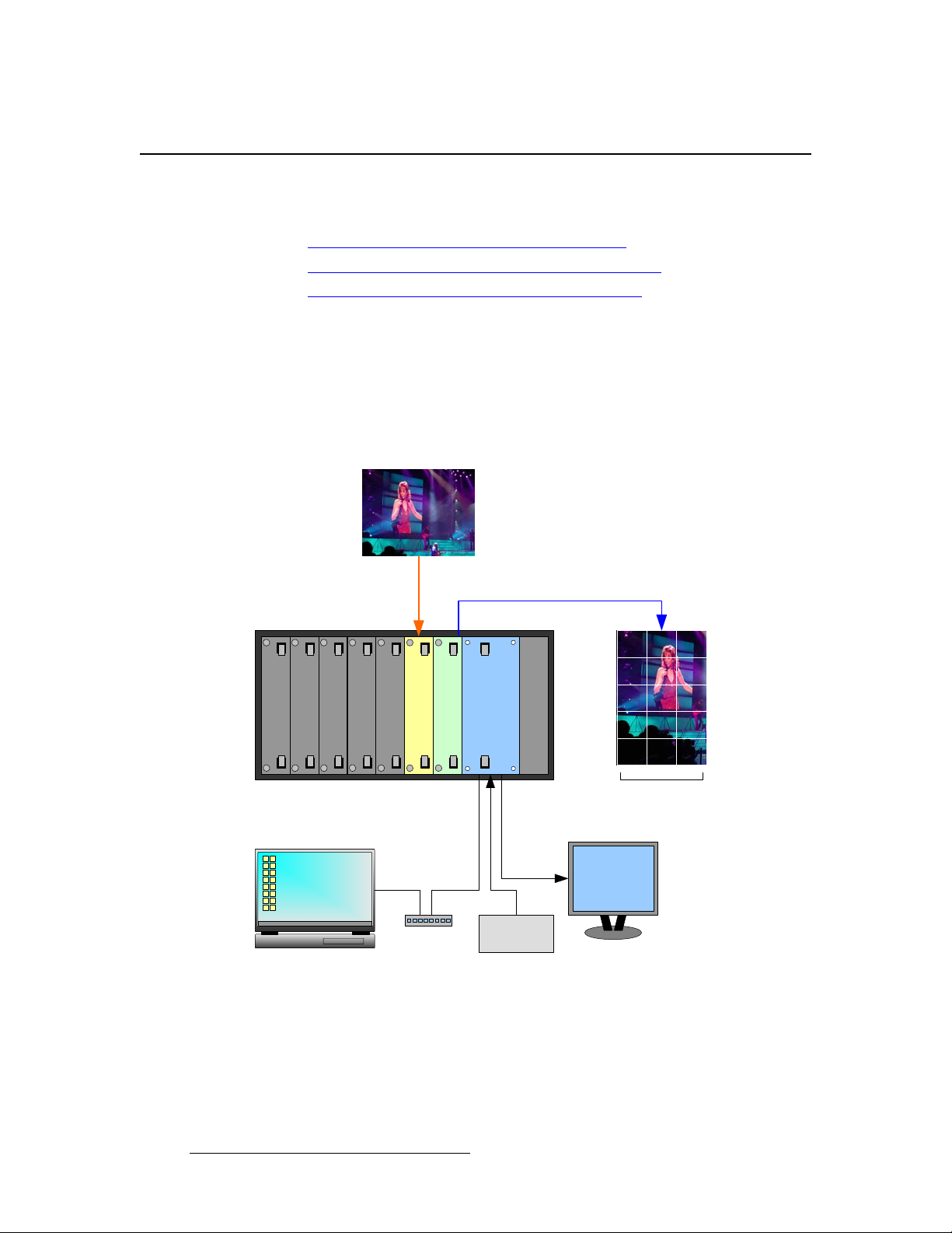
pбеЦдЙ=_~евI=pбеЦдЙ=fеймн=pзмкЕЙI=pбеЦдЙ=lмнймн
The figure below illustrates a sample DX-700 “single bank” configuration. In this
configuration, the bank consists of a single input module and a single output module. One
input source is mapped to one of the output module’s three output connectors, and is used
to drive a single video wall.
Source 1
Blank Panel
Blank Panel
Blank Panel
Blank Panel
Blank Panel
Input Module
Output Module
Laptop PC
(Director Toolset)
Ethernet
Switch
Figure 1-7. Sample system configuration: single input, single output
System Module
Sync
Generator
Power Supply
LED Wall 1
OLite
DVI or RGB
Monitor
30 DX-700 • User’s Guide • Rev 02
Page 31

pбеЦдЙ=_~евI=qкбйдЙ=fеймн=pзмкЕЙлI=rеЦкзмйЙЗ=lмнймн
The figure below illustrates another sample DX-700 “single bank” configuration. In this
diagram, the bank consists of one output module and three input modules. Three different
input sources are mapped to the output module’s three output connections, and are used to
drive three video walls of different sizes and aspect ratios.
Source 1 Source 2 Source 3
NK==fенкзЗмЕнбзе
Connectivity Diagrams
LED Wall 3
MiTRIX
Blank Panel
Blank Panel
Blank Panel
Laptop PC
(Director Toolset)
Input Module
Input Module
Input Module
Ethernet
Switch
Output Module
System Module
Sync
Generator
Power Supply
LED Wall 2
ILite
LED Wall 1
OLite
DVI or RGB
Monitor
Figure 1-8. Sample system configuration: triple input, triple output (ungrouped)
DX-700 • User’s Guide • Rev 02 31
Page 32

NK==fенкзЗмЕнбзе
Connectivity Diagrams
pбеЦдЙ=_~евI=pбеЦдЙ=fеймн=pзмкЕЙI=dкзмйЙЗ=lмнймн
The figure below illustrates a sample DX-700 “single bank” configuration. In this diagram,
the bank consists of a single input module and a single output module. A single input
source is mapped to all three of the output module’s output connectors. These outputs are
grouped to display three LED walls simultaneously, creating one large canvas on which to
display the video.
Source 1
Blank Panel
Blank Panel
Blank Panel
Laptop PC
(Director Toolset)
Blank Panel
Blank Panel
Input Module
Ethernet
Switch
Output Module
System Module
Sync
Generator
Power Supply
DVI or RGB
Monitor
LED Wall 1
NX-4
LED Wall 2
NX-4
Figure 1-9. Sample system configuration: single input, triple output (grouped)
LED Wall 3
NX-4
32 DX-700 • User’s Guide • Rev 02
Page 33

OK==e~кЗп~кЙ=lкбЙен ~нбзе
få=qÜáë=`Ü~éíÉê
This chapter provides detailed diagrams of the DX-700’s front and rear panels, along wit h
comprehensive explanations of each.
The following topics are discussed:
• DX-700 Front Panel
• DX-700 Rear Panel
• Module Installation and Configuration
DX-700 • User’s Guide • Rev 02 33
Page 34

2. Hardware Orientation
DX-700 Front Panel
auJTMM=cêçåí=m~åÉä
The figure below illustrates the DX-700 front panel:
31 52 1
ENTER
TEST
PAT
PRESETS
BLACK
Figure 2-1. DX-700 Front Panel, with Home Menu
1) Handles 4) Focus
2) Softkeys 5) Navigation Section
3) Touch Screen 6) Function Section
Following are descriptions of each front panel section:
1) Handles
The front panel includes two recessed handles that enable you to easily insert or
withdraw the chassis from a rack. Chassis weight varies depending on the
number of input and output modules installed. In Appendix A, refer to the
“
Physical and Electrical Specifications” section on page 176 for details.
2) Softkeys
Six un-labeled buttons called “softkeys” are located to the left of the Touch
Screen. Softkey labels (when present) appear as
blue buttons in the Touch
Screen’s left-hand column, indicating an associated function. To activate the
function or access the indicated menu, press the blue button on the T ouch Screen,
or press the adjacent softkey.
64
34 DX-700 • User’s Guide • Rev 02
Page 35

2. Hardware Orientation
DX-700 Front Panel
3) Touch Screen
The Touch Screen is the DX-700’s primary user interface, which enables you to
access (or activate) all menus and functions in a variety of ways. Refer to the
“
Touch Screen” section on page 36 for details.
4) Focus
The cyan-colored “focus” highlight indicates a button that can be activated by
pressing
used to move the focus. Refer to the Navigation Section below for details.
5) Navigation Section
The Navigation Section includes four “arrow” buttons (left, right, up and down),
plus a central
ENTER
ENTER in the Navigation Section. The Navigation buttons are also
ENTER button.
Figure 2-2. Navigation Section
On screen, the arrow buttons are used to move the “focus” from button to button,
and they are also used to scroll lists up and down. T o activate a function using the
navigation keys, move the focus to the desired button and press
6) Function Section
The Function Section includes three buttons dedicated to single functions.
TEST
PAT
PRESETS
BLACK
Figure 2-3. Function Section
~ Press TEST PAT to access the Test Pattern Menu, which enables you
to assign an internal test pattern to selected outputs. Refer to the “
Patterns” section on page 38 for additional details.
~ Press PRESETS to access the Preset Management Menu, which
allows you to recall and manage presets. In Chapter 4, refer to the
“
Using the Preset Management Menu” section on page 103 for details.
ENTER.
Test
Important
The TEST PAT and PRESETS buttons are not accessible
from all menus (e.g., when you are in a Wizard).
~ The BLACK button is a toggle. Press once to take all outputs to black.
The button lights when pressed, and the DX-700 displays a black test
pattern on all enabled outputs. Press again to restore the previous
output video configuration.
DX-700 • User’s Guide • Rev 02 35
Page 36

2. Hardware Orientation
DX-700 Front Panel
qзмЕЬ=pЕкЙЙе
The Touch Screen is a 640 x 480 color LCD that shows all menus and functions. Y ou can use the Touch Screen in a variety of ways:
• Press the desired button on the Touch Screen itself.
• Press a softkey that is directly adjacent to a blue Touch Screen button.
• Use the four arrow buttons in the Navigation Section to move the cyan-colored
“focus” highlight to a particular button on screen. Then, press
the highlighted menu or activate the selected function.
qзмЕЬ=pЕкЙЙе=`зеоЙенбзел
The following conventions apply to the Touch Screen:
• Black buttons are used to activate functions and access various menus and
“wizards.” These buttons can only be pressed on the Touch Screen, or accessed
via the navigation keys.
ENTER to access
Figure 2-4. Sample Black Button
• Blue buttons are softkey labels only. These buttons can either be pressed on the
Touch Screen, or activated by pressing the adjacent softkey.
Figure 2-5. Sample Blue “Softkey” Button
• Green buttons appear in pop-up menus or dialogs. These buttons typically offer
a choice (
Figure 2-6. Sample Green “Choice” Button
Yes or No), or a confirmation such as OK.
• Red backgrounds in a pop-up indicate a warning, cauti on, or error condition.
Figure 2-7. Sample Warning Pop-up
36 DX-700 • User’s Guide • Rev 02
Page 37

2. Hardware Orientation
DX-700 Front Panel
• Lists are used to display a variety of stored information, including Presets and
resolution formats.
Figure 2-8. Sample Preset List
• Sliders are used to adjust various display parameters, and each includes a
variety of individual controls:
a
cb
Figure 2-9. Sample Slider
a) Arrows c) Slider Bar
b) Slider Button d) Value Box
Following are descriptions of each slider section:
a) Arrows
Press the left or right Arrows to increase or decrease the selected value (or
parameter) by one digit with each press. This is a “fine” adjustment.
b) Slider Button
Press and drag the Slider button left or right to increment or decrement the
selected value. This is a “course” adjustment.
c) Slider Bar
Touch the Slider Bar at any location (to the left or right of the Slider Button) to
instantly move the button to that location. This is also a “course” adjustment.
d
DX-700 • User’s Guide • Rev 02 37
Page 38

2. Hardware Orientation
DX-700 Front Panel
d) Value Box
The Value Box always displays the selected parameter’s current value, and the
box updates as you make adjustments. For
Box to display a keypad, a sample of which is shown below:
Figure 2-10. Sample keypad
direct numeric entry, press the Value
~ Press the desired number buttons for the selected parameter. Entries
shift left in the register.
~ Press Clear to clear the entire register.
~ Press < Bksp to clear the last digit entered.
~ Press Cancel to cancel numeric entry, and clear the keypad from the
screen. The previous value is retained.
~ Press OK to accept the new value and clear the keypad.
qЙлн=m~ннЙкел
The DX-700 includes several locations where internal test patterns can be enabled:
• In the Input Management Menu, select an input card, then select the {Window
Settings Tab}
. These patterns are used to test a source within its assigned output region
Menu
on the canvas.
• In the DX-700 Management Menu, press {Monitor Setup} to display the Monitor
Output Menu
patterns enable you to display a test pattern on the monitor (that is connected to
the System Module).
• In the DX-700 Management Menu, press {Test Patterns} to display the Output
Selection Menu. Next, select an output to display the Output Test Pattern
. This menu enables you to display a test pattern for the selected output (or
Menu
group of outputs).
. Next, press {Test Pattern} to display the Input Test Pattern
. Next, press {Test Pat} to display the Test Pattern Menu. These
Note
38 DX-700 • User’s Guide • Rev 02
Within the Display Management Menu, a wall’s internal test
patterns can be enabled, but these patterns are not
generated by DX-700.
Page 39

2. Hardware Orientation
DX-700 Front Panel
The following internal test patterns are provided:
• H Gray Ramp
• V Gray Ramp
• Color Bars
• 16 x 16 Grid
• 32 x 32 Grid
• Burst
• 75% Bars
• 50% Gray
• H Gray Steps
• V Gray Steps
• Adj (Adjust) Grid
• Black
• White
• Adj (Adjust) Color
Test patterns can be programmed in any of three forms:
• Each output port contains a test pattern sized to that port's output resolution.
• A single test pattern is created that fills the entire area of all stacked outputs within
an output bank.
• A single test pattern is created that fills the entire area of all outputs when stacking
multiple DX-700 units.
Please note the following additional points:
• The test pattern generator can also be programmed to individually enable or
disable each RGB primary. This feature allows the programmable gray level
pattern to generate any intensity of any primary.
• Any test pattern can be put into diagonal motion.
• The test pattern generator can create raster boxes, which encompass an
individual output's pixel area, the entire stacked output or the source’s perimeter.
In Chapter 4, refer to the “
additional information.
Using the Test Pattern Menu” section on page 148 for
DX-700 • User’s Guide • Rev 02 39
Page 40

2. Hardware Orientation
DX-700 Rear Panel
auJTMM=oÉ~ê=m~åÉä
The figure below illustrates the DX-700 rear panel:
1 2 3
EXP OUT DVI / EXP IN
1 - HD/SDI - 2
EXP OUT DVI / EXP IN
RGBHV
1 - HD/SDI - 2
Y / COMP C / Pb Pr
EXP OUT DVI / EXP IN
RGBHV
1 - HD/SDI - 2
Y / COMP C / Pb Pr
RGBHV
Y / COMP C / Pb Pr
LED OUT 1 LED OUT 2 LED OUT 3
Figure 2-1. DX-700 Rear Panel, with sample DVI I/O configuration
1) Input / Output Section 3) Power Supply
2) System Module
Following are descriptions of each rear panel connector:
1) Input / Output Section
The Input / Output Section provi des seven slots for both input and output
modules, which can be arranged in a variety of configurations and “banks.” Each
module is fully shielded and field-installable.
~ A single “universal” input module is available. Refer to the “Input
Module” section on page 41 f or details.
~ Two different output modules are availab l e (DVI and NNI). Refer to the
“
Output Modules” section on page 45 for details.
~ Refer to the “Input Module” section on page 41 for important rules
governing the configuration and placement of modules.
2) System Module
The System Module is standard on all DX-700 units. It provides connections for
synchronization, monitoring, control and diagnostics. Refer to the “
Module” section on page 51 for details.
GENLOCK EXP
V INH / CS IN LOCK
MONITOR
DIAGNOSTICETHERNETDMX THRUDMX IN
100-240V
50-60 Hz, 5.0 A
System
40 DX-700 • User’s Guide • Rev 02
Page 41

2. Hardware Orientation
DX-700 Rear Panel
3) Power Supply
The Power Supply connects the DX-700 to your facility’s AC power source. The
integral switch turns the unit on and off. Twin fans are provided for cooling. In
Appendix A, refer to the “
page 176 for power details.
Physical and Electrical Specifications” section on
fеймн=jзЗмдЙ
The following topics are discussed in this section:
• Input Module Block Diagram
• Input Module Description
fеймн=jзЗмдЙ=_дзЕв=aб~Цк~г
The figure below illustrates a simplified block diagram of the Input Module:
Input Module
DVI or Dual DVI In
RGB In
SD-SDI, HD-SDI, or
Dual HD-SDI In
YUV In (Composite,
S-Video, Component)
Figure 2-2. Block Diagram - Input Module
Connections
Bus
Expansion Out
Video Out
to next Input Module
or Output Module
fеймн=jзЗмдЙ=aЙлЕкбйнбзе
DX-700 Input Modules provide the system’s input, scaling, and mixing functions. Within
each module, the input source is selected from among the various input connectors and
scaled to the required size and position in the final display. The module is fully shielded
and field-installable.
DX-700 • User’s Guide • Rev 02 41
Page 42

2. Hardware Orientation
DX-700 Rear Panel
The figure below illustrates the DX-700’s universal Input Modul e.
1
2
EXP OUT DVI / EXP IN
3
RGBHV
4
1 - HD/SDI - 2
Y / COMP C / Pb Pr
5
6
7
2
1
Figure 2-3. DX-700 Input Module
1) Thumb Screws 5) HD / SDI Input
2) Latches 6) Component Input
3) Expansion Out 7) DVI / Expansion Input
4) RGBHV Input
1) Thum b Screws
Two captive, spring-loaded Thumb Screws are provided to secure the module to
the DX-700 chassis.
2) Latches
Two Latches are provided to ensure precise module insertion and extraction.
Care is required when inserting or removing modules. Refer to the “
Module
Insertion and Extraction” section on page 57 for instructions.
3) Expansion Out
One DVI-I connector is provided for the EXP OUT (Expansion Out) port, which is
used only with external and cross-bank stacking configurations. The port
connects input modules together, guaranteeing that inputs are identical across
banks or units. Input 1 on the “master” must connect to input 1 on the slave, etc.
42 DX-700 • User’s Guide • Rev 02
Page 43

2. Hardware Orientation
DX-700 Rear Panel
~ For external stacking configurations between units, the EXP OUT port
(on the “master”) connects to the
unit’s input module. Additional units can be stacked in this manner.
DVI / EXP IN port on the first slave
Unit 1
Input Module 1
EXP OUT DVI / EXP IN
RGBHV
Pr
Input
Input
Blank
Blank
Blank
Input
Output
System
Master
Power
Slave
Input
Input
Input
System
Power
Output
Unit 2
Input Module 1
Blank
Blank
Blank
Figure 2-4. Sample Expansion Port configuration, external stacking
~ For cross-bank stacking configurations in one unit, the EXP OUT port
(on bank 1) connects to the
banks can be stacked in this manner.
DVI / EXP IN port (on bank 2). Additional
Bank 1 Bank 2
Unit 1
Input Module 1
EXP OUT
RGBHV
DVI / EXP IN
Input Module 1
Pr
Unit 2
Input
Input
Blank
Input
Input
Output
Output
Power
System
Figure 2-5. Sample Expansion Port configuration, cross-bank stacking
In Chapter 1, refer to the “DX-700 Stacking” section on page 26 for additional
information about stacking and expansion links. In Appendix A, refer to the “
Connector Pinouts” section on page 180 for pinout information.
DVI-I
DX-700 • User’s Guide • Rev 02 43
Page 44

2. Hardware Orientation
DX-700 Rear Panel
4) RGBHV Input
One 15-pin D connector is provided for the RGBHV input. This port accepts
RGBHV inputs up to QXGA, with a maximum 240 MHz pixel clock. The pixel
clock is the speed at which pixels are drawn or refreshed. In Appendix A, refer to
the “
Analog 15-pin D Connector” section on page 179 for pinout information.
5) HD / SDI Input
Two BNC connectors (labelled 1 and 2) are provided for the HD / SDI input. A
variety of input combinations are possible:
~ 2 x SD-SDI — Connect one SD-SDI source to connector 1, and a second
~ 2 x HD-SDI — Connect one HD-SDI source to connector 1, and a
~ 1 x SD-SDI, 1 x HD-SDI — Connect one SD-SDI source to either
~ 1 x Dual HD-SDI — Connect the (two-wire) Dual HD-SDI source to
In all cases, the DX-700 auto-detects which inputs have video present.
6) Component Input
Three BNC connectors (Y / Comp, C / Pb and Pr) are provided for either a
composite, S-Video or Component input. In Chapter 3, refer to the “
Connection Table” section on page 68 for a table of format combinations.
7) DVI / Expansion Input
One DVI-I connector is provided for the DVI / EXP IN port. This port accepts
single or dual DVI inputs, with resolutions up to QXGA (2048 x 1536) with a
maximum 240 MHz pixel clock. In Appendix A, refer to the “
Pinouts” section on page 180 for pinout information.
SD-SDI source to the connector
second HD-SDI source to connector
connector
connectors
1 or 2, and one HD-SDI source to the other connector.
1 and 2.
2.
2.
Format
DVI-I Connector
44 DX-700 • User’s Guide • Rev 02
Page 45

2. Hardware Orientation
DX-700 Rear Panel
lмнймн=jзЗмдЙл
The following topics are discussed in this section:
• Output Module Description
• Output Module Block Diagrams
• DVI Output Module
• NNI Output Module
lмнймн=jзЗмдЙ=aЙлЕкбйнбзе
The DX-700 offers two output modules:
• The DVI Output Module is designed for existing (legacy) LED products such as
MiPIX, DLite 7 and OLite 612.
• The NNI Output Module is designed for next generation LED products, such as
the NX-4, NX-6, FLX, and any future NNI-based LED tiles.
Each output module (regardless of type), provides three outputs. These outputs can drive
one or more attached displays from any portion of a selected source image. In Chapter 1,
refer to the “
module is fully shielded and field-installable.
Please note:
• A maximum of two output modules is allowed per bank.
• Each individual output is limited to a maximum resolution, depending on the type
• If a single output exceeds the maximum parameter, outputs can be “grouped” in
Understanding Banks” section on page 24 for more information. Each output
of module:
~ For DVI output modules, each output is limited to 800x600 pixels.
~ For NNI output modules, each output is limited to 1024x768 pixels.
order to increase the size of the output image. In Chapter 1, refer to the “
of Operation” section on page 20 for additional information on maximum output
resolution and the DX-700’s “canvas.”
Theory
Note
Important
The output aspect ratio is flexible. For example, for DVI
modules, you can set the ratio to 800 x 600, 600 x 800,
300 x 1600, etc.
You cannot mix tile categories within a bank. Thus, the
following combination is
not allowed:
• Output Module 1: MiPIX, DLite 7 (legacy tiles)
• Output Module 2: NX-4 (next generation tiles)
DX-700 • User’s Guide • Rev 02 45
Page 46

2. Hardware Orientation
DX-700 Rear Panel
lмнймн=jзЗмдЙ=_дзЕв=aб~Цк~гл
The figure below illustrates a simplified block diagram of the DVI Output Module:
DVI Output Module
DVI Out 1
DVI Out 2
DVI Out 3
from Input Module(s)
Video In
Figure 2-6. Block Diagram - DVI Output Module
Bus
Connections
Connections
Bus
Video Out
to System Module
The figure below illustrates a simplified block diagram of the NNI Output Module:
NNI Output Module
NNI Out 1
NNI Out 2
NNI Out 3
from Input Module(s)
Video In
Figure 2-7. Block Diagram - NNI Output Module
Bus
Connections
Connections
Bus
Video Out
to System Module
46 DX-700 • User’s Guide • Rev 02
Page 47

2. Hardware Orientation
asf=lмнймн=jзЗмдЙ
The figure below illustrates the DX-700’s DVI Output Module.
1
2
LED OUT 1 LED OUT 2 LED OUT 3
3
DX-700 Rear Panel
2
1
Figure 2-8. DX-700 DVI Output Module
1) Thumb Screws 3) DVI Outputs
2) Latches
1) Thum b Screws
Two captive, spring-loaded Thumb Screws are provided to secure the module
into the DX-700 chassis.
2) Latches
Two Latches are provided to ensure precise module insertion and extraction.
Care is required when inserting or removing modules. Refer to the “
Insertion and Extraction” section on page 57 for instructions.
3) DVI Outputs
Three DVI-I connectors are provided for DVI Outputs, which connect to existing
(legacy) LED products such as MiPIX and OLite 612. Each output can drive one
attached display from any portion of a selected source image. Each output is
Module
DX-700 • User’s Guide • Rev 02 47
Page 48

2. Hardware Orientation
DX-700 Rear Panel
limited to a maximum resolution of 800 x 600. In Appendix A, refer to the “DVI-I
Connector Pinouts” section on page 180 for pinouts.
Warning
The DVI-I connectors on the DVI output module use
proprietary signals and pinouts.
Do not connect the output of a DVI output module to anything
other than the input of a Barco DVI LED tile. Even though the
connector is a DVI-I type connector, it is not a DVI signal, and
serious damage could result if, for example, the output was
plugged into a DVI-type monitor.
48 DX-700 • User’s Guide • Rev 02
Page 49

2. Hardware Orientation
kkf=lмнймн=jзЗмдЙ
The figure below illustrates the DX-700’s NNI Output Module.
1
2
LED OUT 1 LED OUT 2 LED OUT 3
3
DX-700 Rear Panel
2
1
Figure 2-9. DX-700 NNI Output Module
1) Thumb Screws 3) NNI Outputs
2) Latches
1) Thum b Screws
Two captive, spring-loaded Thumb Screws are provided to secure the module
into the DX-700 chassis.
2) Latches
Two Latches are provided to ensure precise module insertion and extraction.
Care is required when inserting or removing modules. Refer to the “
Insertion and Extraction” section on page 57 for instructions.
3) NNI Outputs
Three HDMI-type connectors are provided for NNI Outputs, which connect to new
LED products such as NX-4. Each output can drive one attached display from any
portion of a selected source image, and each output is limited to a maximum
resolution of 1024 x 768.
Module
DX-700 • User’s Guide • Rev 02 49
Page 50

2. Hardware Orientation
DX-700 Rear Panel
In Appendix A, refer to the “NNI Connector” section on page 184 for pinout
information.
Warning
The HDMI-type connectors on the NNI Output Module use
proprietary signals and pinouts.
Do not connect the output of an NNI Output Module to
anything other than the input of a Barco NNI LED tile. Even
though the connector is an HDMI-type connector, it is not an
HDMI signal, and serious damage could result if, for example,
the output was plugged into an HDMI monitor.
50 DX-700 • User’s Guide • Rev 02
Page 51

2. Hardware Orientation
DX-700 Rear Panel
pулнЙг=jзЗмдЙ
One System Module is a requirement in all DX-700 units, and its location is always to the left of the well as connections for synchronization, monitoring, control and diagnostics.
The figure below illustrates the System Module:
Power Supply. The module provides the real-time OS (Operating System), as
1
2
GENLOCK EXP
3
V INH / CS IN LOCK
7
4
8
5
MONITOR
DIAGNOSTICETHERNETDMX THRUDMX IN
9
6
10
2
1
Figure 2-10. DX-700 System Module
1) Screws 6) DVI Monitor Out
2) Latches 7) DMX In
3) Genlock Inputs 8) DMX Thru
4) Expansion Lock Output 9) Ethernet
5) RGBHV Monitor Out 10) Diagnostic Port
1) Screws
Four standard Screws are provided to secure the module into the DX-700
chassis. The System Module does not use thumb screws.
DX-700 • User’s Guide • Rev 02 51
Page 52

2. Hardware Orientation
DX-700 Rear Panel
2) Latches
Two Latches are provided to ensure precise module insertion and extraction.
Care is required when inserting or removing modules. Refer to the “
Insertion and Extraction” section on page 57 for instructions.
3) Genlock Inputs
Two BNC connectors are provided for the DX-700’s Genlock Inputs, one each for
H / CS IN and V IN. These connections enable the DX-700 to lock to an external
black burst or composite sync signal.
4) Expansion Lock Output
One BNC connector is provided for the DX-700’s Expansion Lock Output (EXP
LOCK), a signal that enables the DX-700 to synchronize additional DX-700 units
— when external stacking is used. The
connects to the
synchronized in this manner.
Genlock
Source
V INH / CS IN LOCK
Module
EXP LOCK port (on the “master”)
H / CS IN connector on the first slave unit. Additional units can be
Unit 1
System Module
Master
GENLOCK EXP
Input
Input
Blank
Blank
Blank
DMX THRUDMX IN
Input
System
Power
Output
GENLOCK EXP
V INH / CS IN LOCK
Input
Input
DMX THRUDMX IN
Unit 2
System Module
Blank
Blank
Blank
Input
Output
System
Figure 2-11. Sample genlock configuration, external stacking
Note that when the EXP LOCK signal connects to a slave DX-700, it also serves
as a serial communication link between units to provide real-time command
execution across all connected DX-700s.
5) RGBHV Monitor Out
One 15-pin D connector is provided for the RGBHV Monitor Output. In
Appendix A, refer to the “
RGB connector pinouts. Refer to the “
Analog 15-pin D Connector” section on page 179 for
DX-700 Monitor Outputs” section on
page 54 for additional information on both monitor output ports.
Slave
Power
52 DX-700 • User’s Guide • Rev 02
Page 53

2. Hardware Orientation
DX-700 Rear Panel
6) DVI Monitor Out
One DVI-I connector is provided for the DVI Monitor Output. In Appendix A,
refer to the “
pinouts. Refer to the “
information on both monitor output ports.
7) DMX In
One XLR5 connector is provided for DMX Input. This port enables you to control
the DX-700 from a lighting console or other DMX-capable device. In Appendix A,
refer to the “
DVI-I Connector Pinouts” section on page 180 for DVI-I connector
DX-700 Monitor Outputs” section on page 54 for additional
DMX Connector” section on page 184 for pinouts.
Note
8) DMX Thru
One XLR5 connector is provided for DMX Thru. This port enables you to loop
control from the “master” DX-700 to additional slave units. In Appendix A, refer to
the “
DMX Connector” section on page 184 for pinouts.
Note
9) Ethernet
One RJ-45 connector is provided for 100BaseT Ethernet communications with
DX-700, using a socket connection over TCP/IP. The port is typically used for
communications with Barco’s
The DX-700 defaults to DHCP operation. The default static IP address is
192.168.000.200. Please note:
DMX control is currently not implemented.
DMX control is currently not implemented.
Director Toolset Graphical User Interface (GUI).
~ The DX-700 returns to the DHCP mode after a factory reset.
~ This address can be changed using the Ethernet Menu. In Chapter 4,
refer to the “
In Appendix A, refer to the “
pinouts.
10) Diagnostic Port
One 9-pin D connector (Diagnostic) is provided for RS-232 serial
communications with the DX-700. The port is reserved for factory and technical
support use only.
In Appendix A, refer to the “
connector illustration.
Using the Ethernet Menu” section on page 142 for details.
Ethernet Connector” section on page 183 for
Diagnostic Connector” section on page 183 for a
DX-700 • User’s Guide • Rev 02 53
Page 54

2. Hardware Orientation
DX-700 Rear Panel
auJTMM=jзебнзк=lмнймнл
The DX-700 provides two identical monitor outputs, one each in RGB and DVI formats.
Both outputs show the same video. Please note:
• Each port’s output resolution can be selected, from 640 x 480 up to 2048 x 1080.
• Each monitor port enables you to view any of the active primary outputs, or the
ports can be configured to display the overall output image (all wall sections) of a
selected bank.
• A scaler within the System Module scales the selected video to fit into the
monitor's output resolution.
• The output that you wish to monitor is selected on the Monitor Output Menu, and
the selection applies to both the RGB and DVI monitor outputs. In Chapter 4,
refer to the “
Using the Monitor Output Menu” section on page 150 for details.
54 DX-700 • User’s Guide • Rev 02
Page 55

jзЗмдЙ=fелн~дд~нбзе=~еЗ=`зеСбЦмк~нбзе
The following topics are discussed in this section:
• Module Configuration Rules
• Module Insertion and Extraction
• Storing Sp a re Modules
jзЗмдЙ=`зеСбЦмк~нбзе=oмдЙл
DX-700 input and output modules can be configured in a variety of ways, but important sets
of rules apply to their placement. As a prerequisite, ensure that you are familiar with th e
“
Understanding Banks” section, on page 24 in Chapter 1.
Please note the following important “module” rules:
• In the most basic of DX-700 “single bank” configurations, you must have at least
one input module and one output module — to rout e video to an LED wall.
• As you face the rear of the chassis, the right-most module within the entire Input /
Output Section must always be an Output Module, and it must always be right-
justified against the System Module.
2. Hardware Orientation
Module Installation and Configuration
Input / Output Section
Input
Input
Blank
Blank
Blank
Correct Justification Incorrect Justification
Figure 2-12. Right justification of Output Modules against the System Module
Input
Output
Power
System
Input / Output Section
Input
Input
Blank
Blank
Input
Output
Blank
System
• Within any bank, all modules must be adjacent to each other — with no blank
panels in-between, and all
Bank 1
Input
Input
Blank
Blank
Blank
Output
Output
Output Module(s) are always right-justified.
Bank 1
Blank
Input
Output
Blank
Input
Power
System
Blank
Output
System
Power
Power
Correct Justification Incorrect Justification
Figure 2-13. Adjacent modules within a bank
DX-700 • User’s Guide • Rev 02 55
Page 56

2. Hardware Orientation
Module Installation and Configuration
• In multi-bank configurations, all banks must be directly adjacent to one another,
with no blank panels in between.
Output
Bank 2
Input
Input
Output
With the exception of “spare” modules, if the DX-700
Bank 1
Input
Input
Blank
Correct Justification
Figure 2-14. Adjacent banks
Important
determines that any modules are incorrectly installed (or
missing), a
prompts you to power down the DX-700 and re-configure your
modules properly.
If the above prompt occurs, and provided that a System
Module is properly installed, on the
Menu
button, and access a subset of management functions. In
Chapter 4, refer to the “
page 77 for details.
Bank 1 Bank 2
System
Input
Power
Input
Output
Incorrect Justification
Blank
Input
Input
Output
System
Startup Diagnostic Menu appears which
Startup Diagnostic
you will be able to press the {DX-700 Management}
Power-Up Initialization” section on
Power
Important
Important
Important
The DX-700 will not recognize modules that are installed to
the left of a blank panel. They will be treated as spares.
Refer to the “
Storing Sp are Modules” section on p age 59 for
additional details.
Multi-bank configurations are currently not implemented.
For proper chassis cooling, slots that do not contain
input or output modules must always have blank panels
installed.
56 DX-700 • User’s Guide • Rev 02
Page 57

2. Hardware Orientation
Module Installation and Configuration
jзЗмдЙ=fелЙкнбзе=~еЗ=bснк~Енбзе
The following procedures apply to input, output, and system modules.
jзЗмдЙ=fелЙкнбзе
To insert a module:
1. Ensure that the DX-700 power is off.
2. Orient the module so that the power connector is at the bottom.
Power
Connector
Figure 2-15. Rear view of module: correct orientation of power connector
3. Carefully insert the module, and push it into the chassis until the module’s top
latch is stopped against the chassis.
Chassis
Latch
Insert module
until the latch
stops against
the chassis
Module
Figure 2-16. Module latch stopped against chassis
DX-700 • User’s Guide • Rev 02 57
Page 58

2. Hardware Orientation
Module Installation and Configuration
4. Raise the top latch until you can slide the module farther into the chassis — up to
the latch’s pivot point.
Raise latch, slide
module farther in,
until it stops
against pivot point
Figure 2-17. Latch raised, module inserted to pivot point
5. Simultaneously push both latches towards the center of the module, until the
module is fully seated against the chassis.
Pivot
Point
Caution
Always push both latches simultaneously. If you use one
latch only, you can damage the module.
Simultaneously
push both latches
towards the center
of the module
CAUTION:
Always use both
latches. Damage
will result if you
use a single latch
Figure 2-18. Latches pushed simultaneously towards center
6. Tighten both retaining screws to secure the module.
58 DX-700 • User’s Guide • Rev 02
Page 59

2. Hardware Orientation
Module Installation and Configuration
jзЗмдЙ=bснк~Енбзе
To extract a module:
1. Ensure that the DX-700 power is off.
2. Loosen both retaining screws on the module.
3. Simultaneously push both latches away from the center of the module.
Caution
Always push both latches simultaneously. If you use one
latch only, you can damage the module.
4. When both latches are clear of the chassis, remove the module.
pнзкбеЦ=pй~кЙ=jзЗмдЙл
The DX-700 enables you to store spare modules within a chassis.
Use the following steps to store spare modules in your DX-700 chassis:
1. Configure a bank properly, according to the rules outlined in the “Module
Configuration Rules” section on page 55.
2. Install a blank panel immediately to the left of the bank’s left-most input module.
3. In the remaining slots, insert spare input and output modules as desired. The
DX-700 will ignore these modules during initialization, and treat them as spares.
Spares Bank 1
Input
Input
Output
Blank
Input
Input
Output
Power
System
Figure 2-19. Spare Modules
DX-700 • User’s Guide • Rev 02 59
Page 60

2. Hardware Orientation
Module Installation and Configuration
60 DX-700 • User’s Guide • Rev 02
Page 61

PK==fåëí~ää~íáçå
få=qÜáë=`Ü~éíÉê
This chapter provides detailed instructions for installing the DX-700 hardware. The
following topics are discussed:
• Safety Precautions
• Unpacking and Inspection
• Site Preparation
• Cable and Adapter Information
• Rack-Mount Installation
• Power Installation
• Signal Connection
• Format Connection Table
DX-700 • User’s Guide • Rev 02 61
Page 62

3. Installation
Safety Precautions
p~СЙну=mкЙЕ~мнбзел=
For all DX-700 installation procedures, observe the following important safety and handling
rules to avoid damage to yourself and the equipment:
• To protect users from electric shock, ensure that the power supplies for each unit
connect to earth via the ground wire provided in the AC power cord.
• The AC Socket-outlet should be installed near the equipment and be easily
accessible.
rей~ЕвбеЦ=~еЗ=fелйЙЕнбзе=
Before opening the DX-700 box, inspect it for damage. If you find any dama ge, notify the
shipping carrier immediately for all claims adjustments. As you open the box, compare its
contents against the packing slip. If you find any shortages, contact your Barco sales
representative.
Once you have removed all the components from their packaging and checked that all the
listed components are present, visually inspect each unit to ensure there was no damage
during shipping. If there is damage, notify the shipping carrier immediately for all claims
adjustments.
páíÉ=mêÉé~ê~íáçå=
The environment in which you install your DX-700(s) should be clean, properly lit, free from
static, and have adequate power, ventilation, and space for all components.
`~ДдЙ=~еЗ=^З~йнЙк=fеСзкг~нбзе
The table below provides information regarding supplied cables and adapters:
Table 3-1. DX-700 cables and adapters
Cable / Adapter Description Quantity
AC Power Cord 7 foot, 10A 1 US, 1 EU
Ethernet Cable 15M 1
Crossover adapter 1
DVI Cable 5 M. One cable provided with each DVI output module 1
NNI Cable Latching cable, 7.5 M. One cable provided with each NNI output module 1
62 DX-700 • User’s Guide • Rev 02
Page 63

Please note:
• No cables are supplied with input modules. Customers must provide their own
DVI-I, RGB, and SDI cables. Some cables (e.g., DVI-I) ca n be pu rch ased from
Barco. Please contact your Barco sales representative for details.
o~ÅâJjçìåí=fåëí~ää~íáçå
DX-700 units are designed to be rack mounted and are supplied with front rack-mount
hardware. Please note the following important points:
• Rear rack-mount brackets are installed on the base unit, as shipped.
• When rack mounting the unit, remember that the maximum ambient operating
temperature for the unit is 40 degrees C.
• Leave sufficient front and rear space to ensure that the airflow through the fan and
vent holes is not restricted.
• When installing equipment into a rack, distribute the units evenly to prevent
hazardous conditions that may be created by uneven weight distribution.
• Connect the unit only to a properly rated supply circuit.
• Reliable grounding (earthing) of rack-mounted equipment shou ld be maintained.
• Rack mount the unit from the front rack ears using four rack screws (not supplied).
Rack threads may be metric or otherwise — depending upon the rack type.
• Install the lower of the two mounting holes first.
3. Installation
Rack-Mount Installation
mçïÉê=fåëí~ää~íáçå
Use the following steps to install power to the DX-700:
1. Connect an AC power cord to the AC Power Connector on the rear of the DX-700,
and then to an AC outlet.
2. Connect AC Power cords (or AC adapters) to all peripheral equipment, such as
video sources and PCs. Please note:
3. Ensure that your LED wall(s) are properly assembled, and that all power cords are
distributed and connected to all tiles — in the proper sequence. Refer to your
specific LED tile’s User’s Guide for details.
~ Connect each unit only to a properly rated supply circuit.
~ Reliable grounding of rack-mounted equipment should be maintained.
DX-700 • User’s Guide • Rev 02 63
Page 64

3. Installation
Power Installation
mзпЙк=`зкЗLiбеЙ=sздн~ЦЙ=pЙдЙЕнбзе
DX-700 is rated to operate with the following specifications:
• Input Power: 100-240 VAC, 50-60 Hz
• Power Consumption: 500 watts maximum
DX-700 performs line voltage selection automatically, and no user controls are required.
The AC power cords must be accessible so that they can be removed during field servicing.
Warning
Figure 3-1. Tandem Prong-type Plug
Avertissement
When the DX-700 is used in the 230-volt mode, a UL listed
line cord rated for 250 volts at 15 amps must be used and
must conform to IEC-227 and IEC-245 standards. This cord
will be fitted with a tandem prong-type plug.
The rear panel ON/OFF switch does not disconnect the unit
from input AC power. To facilitate disconnection of AC
power, the power cord must be connected to an accessible
outlet near the unit.
Building Branch Circuit Protection: For 115 V use 20 A, for
230 V use 8 A.
La choix de la ligne de voltage se réalise automatiquement
par le DX-700 Transformateur Graphique. On n'a pas besoin
du controller usager pour la choix de la ligne de voltage.
Warnung
64 DX-700 • User’s Guide • Rev 02
Das DX-700 gerät mu beim Anschlu an 240V ~ mit einer vom
VDE auf 250V/10A geprüften Netzleitung mit einem
Schukostecker ausgestattet sein.
Page 65

pбЦе~д=`зееЙЕнбзе
This section provides basic instructions for connecting physical sources and signals, to and
from the DX-700.
3. Installation
Signal Connection
Note
Setup instructions are provided in Chapter 4, “Operation.”
Use the following steps to connect signals to/from t he DX-700:
1. Input module connections
a. Connect outputs from your selected sources to DX-700’s inputs. The
“universal” input module accepts inputs in analog, component, DVI,
Dual-DVI, HD-SDI, SD-SDI, and Dual HD-SDI formats.
• In Chapter 2, refer to the “
details on all input module connectors.
• For analog connections, refer to the “
Table” section on page 68 for connection details using a
customer supplied breakout cable.
Note
b. Repeat step 1a for all additional input modules in your configuration.
2. Stacking connections
Note
There are no looping inputs on the input module.
Cross-bank stacking and external stacking functions are
currently not implemented.
Input Module” section on page 41 for
Format Connection
3. DVI output module connections
Each DVI output module provides three identical outputs, each limited to a
maximum resolution of 800 x 600.
a. Ensure that your “legacy” LED wall(s) are properly assembled, and that
all data cables are connected to all tiles — in the proper sequence.
Refer to your specific LED tile’s User’s Guide for details.
b. Per your configuration, co nnect the DVI output(s) to the data input(s) of
your LED wall(s). In Chapter2, refer to the “
section on page 47 for details on all module connectors.
c. (Option) If you are using a fiber optic link:
• Ensure that power is properly connected to all Fiberlink units.
• Per your configuration, connect DVI outputs to the inputs of the
Fiberlink Transmitter(s).
• Per your configuration, connect fiber optic cables from the
outputs of the Fiberlink Transmitter(s) to the inputs of the
Fiberlink Receiver(s).
• Connect the output of the Fiberlink Receiver(s) to the data input
of your LED wall(s).
DX-700 • User’s Guide • Rev 02 65
DVI Output Module”
Page 66

3. Installation
Signal Connection
d. Repeat steps 2a through 2c for all additional DVI output modules in your
system configuration.
Important
Warning
4. NNI output module connections
Each NNI output module provides three identical outputs, each limited to a
maximum resolution of 1024 x 768.
a. Ensure that your “new generation” LED walls (such as the Barco NX-4
and FLX) are properly assembled and cabled. Refer to your specific
LED tile’s
b. Per your configuration, co nnect the NNI output(s) to the data input(s) of
your LED wall(s). In Chapter2, refer to the “
section on page 49 for details on all module connectors.
c. (Option) If you are using a fiber optic link:
d. Repeat steps 3a through 3c for all additional NNI output modules in your
system configuration.
You cannot mix output module types within a bank.
The DVI-I connectors on the DVI output module use
proprietary signals and pinouts.
Do not connect the output of a DVI output module to anything
other than the input of a Barco DVI LED tile. Even though the
connector is a DVI-I type connector, it is not a DVI signal, and
serious damage could result if, for example, the output was
plugged into a DVI-type monitor.
User’s Guide for details.
NNI Output Module”
• Ensure that power is properly connected to all Fiberlink units.
• Per your configuration, connect NNI outputs to the inputs of the
Fiberlink Transmitter(s).
• Per your configuration, connect fiber optic cables from the
outputs of the Fiberlink Transmitter(s) to the inputs of the
Fiberlink Receiver(s).
• Connect the output of the Fiberlink Receiver(s) to the data input
of your LED wall(s).
Warning
5. Genlock connections
In Chapter 2, refer to the “System Module” section on page 51 for details on all
module connectors.
a. To genlock the DX-700 using a single sync connection, connect a
composite sync or black burst signal to the
66 DX-700 • User’s Guide • Rev 02
The HDMI-type connectors on the NNI output module use
proprietary signals and pinouts.
Do not connect the output of an NNI output module to
anything other than the input of a Barco NNI LED tile. Even
though the connector is an HDMI-type connector, it is not an
HDMI signal, and serious damage could result if, for example,
the output was plugged into an HDMI monitor.
H / CS IN connector.
Page 67

3. Installation
Signal Connection
b. To genlock the DX-700 using separate connections, connect horizontal
and vertical sync signals to the
H / CS IN and V IN connectors.
Note
6. Director Toolset connections
Director Toolset is required for LED wall calibration and certain advanced LED
configurations, but it is not required for initial setup. The DX-700 Setup Wizard is
used for “basic” setups.
a. Connect the Ethernet port on your laptop PC to the Ethernet port on
DX-700. Use a crossover cable for a direct connection, or use a
standard Ethernet cable in conjunction with an Ethernet switch.
b. Ensure that the Director Toolset is properly installed on the laptop PC.
7. Monitor connections
a.
Connect an analog monitor to the RGB Monitor output, and/or a DVI
monitor to the
show the same monitor signal.
8. DMX connections
Note
This completes system signal connection. Please continue with system setup, menu
orientation and operations, as outlined in Chapter 4, “
To “freerun” DX-700, no sync connections are required. Use
Genlock Menu to select freerun. In Chapter 4, refer to
the
Understanding Genlock Options” section on page 153.
the “
DVI Monitor output, per your requirements. Both outputs
DMX control is currently not implemented.
Operation” on page 69.
DX-700 • User’s Guide • Rev 02 67
Page 68

3. Installation
Format Connection Table
cзкг~н=`зееЙЕнбзе=q~ДдЙ
Use the following table to connect various source formats to the DX-700, using the
system’s
Cells with checks denote the connections required for the indicated format .
YUV input (3 x BNC connectors) on the input module. Please note:
• RGB format — typical devices: Computers
• S-Video (Y/C) format — typical devices: S-Video DVD or VCR
• YUV or YP
(Betacam) format — typical devices: DVD player, Betacam deck
bPr
• Composite format — typical devices: NTSC/PAL DVD or VCR
Table 3-2. Analog Input Combinations using YUV input
Input
Connector
Y
U
V 3 (P
Composite
Video
S-Video
(Y/C)
33 (Luma)
3 (Chroma)
3 (Luma) 3 (G)
3 (P
YUV
(YP
)
bPr
) 3 (B)
b
) 3 (R)
r
RGB
Sync on G
68 DX-700 • User’s Guide • Rev 02
Page 69

QK==léÉê~íáçå
få=qÜáë=`Ü~éíÉê
This chapter provides comprehensive menu descriptions and detailed operating
instructions for the DX-700. The following topics are discussed:
• Quick Setup and Operations
• Quick Function Reference
• Controlling the DX-700
• Power-Up Initialization
• Using the Home Menu
• Output Table Description
• Using the Setup Wizard
• Using the Input Wizard
• Using the Preset Management Menu
• Using the Input Management Menu
• Using the Display Management Menu
• Using the DX-700 Management Menu
• Front Panel Lockout
DX-700 • User’s Guide • Rev 02 69
Page 70

4. Operation
Quick Setup and Operations
nмбЕв=pЙнмй=~еЗ=lйЙк~нбзел
For the optimum speed in system setup and operations, this section provides a quick
“recipe” for system setup and operations. Links are provided for each complete procedure
outlined below.
Important
This quick start procedure works for Barco (legacy) LED
products such as MiPIX, DLite 7 and OLite 612, and newer
NNI-based LED products such as NX-4 and NX-6.
The procedure does
such as MiTRIX, MiSPHERE and MiSTRIP. For those
products, please refer to the “
Guide” for instructions.
not work for “creative” LED products
Director Toolset User’s
Use the following “recipe” for quick system setup and operations:
1. Ensure that your LED wall(s) are properly installed and cabled.
2. Ensure that the DX-700 is properly installed in your equipment rack. In Chapter 3,
refer to the “
3. Ensure that all DX-700 modules are firmly seated and installed in the proper
configuration. In Chapter 2, refer to the “
section on page 55 for instructions.
4. Ensure that all sources and signals are properly connected to/from the DX-700. In
Chapter 3, refer to the “
5. Turn on power to your LED walls and Fiberlink connections.
6. Turn on power to the DX -7 00 . Refe r to th e “Power-Up Initialization” section on
page 77 for details.
7. If you are using the DX-700 for the first time, or if it has just returned from a show,
perform a factory reset to remove saved presets and restore system default
settings. Refer to the “
more information.
8. Calibrate the Touch Screen. Refer to the “Using the Front Panel Display
Adjustments Menu” section on page 145 for details.
9. If you wish to set a specific delay mode (other than Standard delay mode), access
the
Reduced/Minimum Delay Menu and “pre-select” the desired mode. Refer to
the “
Pre-selecting the Delay Mode” section on page 159 for instructions on
setting and changing the delay mode.
10. Run the Setup Wizard to set up your LED wall outputs and create “groups.”
Refer to the “
Rack-Mount Installation” section on page 63 for instructions.
Module Installation and Con figuration”
Signal Connection” section on page 65 for instructions.
Performing a Factory Reset” section on page 146 for
Using the Setup Wizard” section on page 80 for instructions.
Important
70 DX-700 • User’s Guide • Rev 02
Ensure that you set up all outputs, and configure all your
output groups.
Page 71

4. Operation
Quick Setup and Operations
11. Run the Input Wi zard. Refer to the “Using the Input Wizard” section on page 93
for complete instructions.
Important
12. Fine tune your inputs as required. Refer to the “Using the Input Management
Menu” section on page 107 for instructions.
13. Fine tune your displays as re quired. Refer to the “Using the Display
Management Menu” section on page 124 for instructions.
14. Recall the desired preset, and you’re ready to go. Refer to the “Using the Preset
Management Menu” section on page 103 for instructions.
This completes the “quick setup” procedure.
Ensure that you save a system “preset” after you configure
each input.
DX-700 • User’s Guide • Rev 02 71
Page 72

4. Operation
Quick Function Reference
nмбЕв=cмеЕнбзе=oЙСЙкЙеЕЙ
Use the following table to quickly access the proper menu for a specific function. Both
hyperlinks and page numbers are provided.
Table 4-1. DX-700 Quick Function Reference Table
How to: Use the Following: Page
Adjust clip to sub-black Adjusting Image Processing Parameters 115
Adjust color space
Adjust display brightness
Adjust image freeze
Adjust image polarity
Adjust image processing
Adjust image strobe
Adjust image to monochrome
Adjust input balance
Adjust input brightness
Adjust input contrast
Adjust input H position
Adjust input H total
Adjust input hue
Adjust input opacity
Adjust input size and position
Adjust input pixel phase
Adjust input RGB brightness
Adjusting Viewport Settings 114
Using the Front Panel Display Adjustments Menu 145
Adjusting Video Effects 119
Adjusting Video Effects 119
Adjusting Image Processing Parameters 115
Adjusting Video Effects 119
Adjusting Video Effects 119
Adjusting Input Balance 118
Adjusting Image Processing Parameters 115
Adjusting Image Processing Parameters 115
Adjusting Input Timing 121
Adjusting Input Timing 121
Adjusting Image Processing Parameters 115
Adjusting Video Effects 119
Using the Input Wizard 93
Adjusting Input Timing 121
Adjusting Input Balance 118
Adjust input RGB contrast
Adjust input saturation
Adjust input sharpness
Adjust input timing
Adjust input V Position
Adjust input view port
Adjust luma tracking
Adjust RGB color key values
Adjust RGB threshold and mask values
Adjust video effects
Adjusting Input Balance 118
Adjusting Image Processing Parameters 115
Adjusting Image Processing Parameters 115
Adjusting Input Timing 121
Adjusting Input Timing 121
Using the Input Wizard 93
Adjusting Image Processing Parameters 115
Adjusting Color Effects 120
Adjusting Color Effects 120
Adjusting Video Effects 119
72 DX-700 • User’s Guide • Rev 02
Page 73

4. Operation
Quick Function Reference
Table 4-1. DX-700 Quick Function Reference Table (Continued)
How to: Use the Following: Page
Adjust viewport settings Adjusting Viewport Settings 114
Adjust wall contrast
Adjust wall contrast
Adjust wall gamma
Adjust wall gamma
Adjust wall OSD
Adjust window settings
Auto acquire the input
Calibrate the display
Change the canvas orientation
Change IP address
Change monitor video
Change Z-Order
Check the firmware version
Control the DX-700
Delay processing pre-selection
Delete a single preset
Delete all presets
Using the Input Wizard 93
Managing LED 126
Using the Input Wizard 93
Managing LED 126
Managing LED 126
Adjusting Window Settings 112
Adjusting Viewport Settings 114
Using the Front Panel Display Adjustments Menu 145
Refreshing the Canvas Size 160
Using the Ethernet Menu 142
Using the Monitor Output Menu 150
Changing Z-Order 110
Using the DX-700 Status Menu 138
Controlling the DX-700 76
Pre-selecting the Delay Mode 159
Delete a Preset 106
Delete All Presets 106
Display a single output on the monitor
Display an input test pattern
Display Fiberlink properties
Display monitor raster box
Display monitor test patterns
Display output raster box
Display output test patterns
Display the canvas (bank) on the monitor
Display wall internal test patterns
Enable a color key
Force display power on/off
Freeze an input
Generate Fiberlink receiver test patterns
Generate Fiberlink transmitter test patterns
Group outputs
Using the Monitor Output Menu 150
Adjusting Window Settings 112
Managing Fiberlink Settings 130
Using the Monitor Output Menu 150
Using the Monitor Output Menu 150
Using the Test Pattern Menu 148
Using the Test Pattern Menu 148
Using the Monitor Output Menu 150
Managing LED 126
Adjusting Color Effects 120
Forcing the Display 133
Adjusting Video Effects 119
Managing Fiberlink Settings 130
Managing Fiberlink Settings 130
Using the Setup Wizard 80
DX-700 • User’s Guide • Rev 02 73
Page 74

4. Operation
Quick Function Reference
Table 4-1. DX-700 Quick Function Reference Table (Continued)
How to: Use the Following: Page
Lock / Unlock front panel Front Panel Lockout 165
Manage a display
Manage an LED display
Manage Ethernet
Manage Fiberlink
Manage Inputs
Perform a factory reset
Perform a system save
Perform a system save
Perform front panel tests
Perform key tests
Perform system diagnostics
Perform system tests
Power on DX-700
Reboot the system
Recall a preset
Rename a preset
Restore default system configurations
Using the Display Management Menu 124
Managing LED 126
Using the Ethernet Menu 142
Managing Fiberlink Settings 130
Using the Input Management Menu 107
Performing a Factory Reset 146
Global Input Management Functions 109
Saving DX-700 Management Settings 164
Using the Diagnostics Menu 143
Using the Diagnostics Menu 143
Using the Diagnostics Menu 143
Using the Diagnostics Menu 143
Power-Up Initialization 77
Rebooting the System 145
Recall a Preset 104
Rename a Preset 105
Performing a Factory Reset 146
Save a preset
Save the system
Save the system
Select an input
Set delay mode processing
Set EDID parameters for any input
Set EDID parameters for the active input
Set monitor format
Set monitor test patterns
Set output test patterns
Set static IP or DHCP
Set up inputs
Set up monitor
Set up outputs
Strobe an input
Using the Input Wizard 93
Global Input Management Functions 109
Saving DX-700 Management Settings 164
Using the Input Wizard 93
Pre-selecting the Delay Mode 159
Using the EDID Menu 151
Adjusting Image Processing Parameters 115
Using the Monitor Output Menu 150
Using the Monitor Output Menu 150
Using the Test Pattern Menu 148
Using the Ethernet Menu 142
Using the Input Wizard 93
Using the Monitor Output Menu 150
Using the Setup Wizard 80
Adjusting Video Effects 119
74 DX-700 • User’s Guide • Rev 02
Page 75

4. Operation
Quick Function Reference
Table 4-1. DX-700 Quick Function Reference Table (Continued)
How to: Use the Following: Page
Test communications Using the Diagnostics Menu 143
Test the display
Test the system
Use the DX-700 Management Menu
Use the EDID menu
Use the Genlock menu
Use the Home Menu
Use the Input Wizard
Use the Setup Wizard
View Ethernet status
View system status
Using the Diagnostics Menu 143
Using the Diagnostics Menu 143
Using the DX-700 Management Menu 134
Using the EDID Menu 151
Understanding Genlock Options 153
Using the Home Menu 78
Using the Input Wizard 93
Using the Setup Wizard 80
Using the Ethernet Menu 142
Using the DX-700 Status Menu 138
DX-700 • User’s Guide • Rev 02 75
Page 76

4. Operation
Controlling the DX-700
`зенкзддбеЦ=нЬЙ=auJTMM
This section reviews the methods by which you can control the DX-700. The front panel is
ideal for all “basic” system configurations, while the Director Toolset is required for more
advanced system configurations. All control methods are discussed below.
• Touch Screen
Use the Touch Screen to access (activate) all menus and functions. “Touchable”
controls include buttons, arrows, sliders, value boxes, lists, keypads, and graphic
displays of DX-700 modules (with integral buttons). In Chapter 2, refer to the
Touch Screen Conventions” section on page 36 for additional information.
“
• Softkeys
Six un-labeled buttons called Softkeys are located to the left of the T ouch Screen.
Softkey labels (when present) appear as
hand column, indicating an associated function. To activate a function, press the
blue button on the Touch Screen or press the adjacent softkey.
• Navigation Buttons
On the front panel, the Navigation Section includes four “arrow” buttons plus an
ENTER button. As an alternate to pressing Touch Screen buttons, use the arrows
to move the cyan-colored “
function, press
• Function Section
Below the Navigation Section, the Function Section includes three buttons.
~ Press TEST P AT to access the Test Pattern Menu. Refer to the “Using
the Test Pattern Menu” section on page 148 for details.
~ Press PRESETS to access the Preset Management Menu. Refer to the
“
Using the Preset Management Menu” section on page 103 for details.
~ Press BLACK to take all outputs to black. Press again to restore the
previous output video configuration.
• The Director Toolset (version 2.0 or later) is required for more “advanced”
system configurations, including those involving Barco’s “creative” series of tiles
and modules. The
DX-700 and provide it with information concerning tile setup and configuration.
blue buttons in the Touch Screen’s left-
focus” from button to button. To activate a highlighted
ENTER.
Director Toolset is a software application used to control the
Note
Operations of the Director Toolset are not covered in this
guide. Refer to the “
more information.
Director Toolset User’s Guide” for
• The DX-700 can be controlled remotely. Refer to Appendix B, “Remote Control
Protocol” on page 185 for details.
76 DX-700 • User’s Guide • Rev 02
Page 77

mçïÉêJré=fåáíá~äáò~íáçå
Use the following steps to power-up the DX-700:
1. After connecting AC to the DX-700, locate the Power Switch on the rear of the
chassis, and turn the power
splash screen appears.
4. Operation
Power-Up Initialization
ON. While the system is initializing, the DX-700
Figure 4-1. DX-700 Splash Screen
During this interval, the DX-700 discovers how your system’s banks and modules
are configured. After a brief pause, the
2. When using the DX-700 for the first time or when using a system that has just
returned from a show, perform a
Performing a Factory Reset” on page 146.
“
Important
If the above prompt occurs, and provided that a System Module is properly installed, on the
Startup Diagnostic Menu you can press {DX-700 Management} and access a subset of
management functions:
With the exception of “spare” modules, if the system
determines that any modules are incorrectly installed or
missing, a
you to power down the system and re-configure the modules.
Startup Diagnostic Menu appears which prompts
Home Menu appears.
Factory Reset. For details, refer to the
• {Properties}
• {Ethernet}
• {Diagnostic}
• {System Reset}
Refer to the “
DX-700
Using the DX-700 Management Menu” section on page 134 for details on all
management functions.
DX-700 • User’s Guide • Rev 02 77
Page 78

4. Operation
Using the Home Menu
rëáåÖ=íÜÉ=eçãÉ=jÉåì
The figure below illustrates the Home Menu.
Figure 4-2. DX-700 Home Menu
Use the Home Menu to run setup wizards and manage all aspects of DX-700 operations.
On this menu:
• Press {Setup Wizard} to run the Setup Wizard for outputs, followed by the Input
Wizard for input setup. Refer to the “Using the Setup Wizard” section on
page 80 for i nstructions.
• Press {Input Wizard} to run the input wizard, which includes input setup and
preset creation. Refer to the “
instructions.
Using the Input Wizard” section on page 93 for
• Press {Preset Management} to recall presets. Refer to the “Using the Preset
Management Menu” section on page 103 for instructions.
• Press {Input Management} to adjust properties of any active input — such as
wall position, brightness, and effects. Refer to the “
Menu” section on page 107 for instructions.
Using the Input Management
• Press {Display Management} to manage output display (LED) parameters and
Fiberlink module parameters. The
Receiver are used to connect the DX-700 to NNI-based LED tiles via a fiber optic
cable. Refer to the “
for instructions. Refer to Appendix D, “
for more information about the Fiberlink modules.
Using the Display Management Menu” section on page 124
Fiberlink NNI Multi-mode Transmitter and
Fiberlink NNI Installation” on page 205
• Press {DX-700 Management} to view system properties, configure your monitor,
run diagnostics and test patterns, adjust Ethernet properties, save a system “startup” file, reset the system, set genlock parameters, or configure “expert” modes
such as delay processing. Refer to the “
section on page 134 for instructions.
Using the DX-700 Management Menu”
78 DX-700 • User’s Guide • Rev 02
Page 79

lмнймн=q~ДдЙ=aЙлЕкбйнбзе
For your reference, an “output table”' is provided at the top of various DX-700 menus, such
Output Selection Menu shown in the illustration below.
as the
4. Operation
Output Table Description
Output
Table
Figure 4-3. Output Selection Menu (sample)
The table lists the following information from left to right:
• Output: DX-700 Output #. Numbering within a bank is as follows:
4
5
6
Figure 4-4. Output numbering
1
2
3
• Tx: Fiberlink transmitter status: ON, OFF, or -- (n/a).
• Rx: Fiberlink receiver status: ON, OFF, or -- (n/a).
• Tiles: # of tiles detected, as connected to the specific output.
• Type: Type of Barco LED tile.
In the table, the color of the text is significant:
• White text indicates “tiles not detected.”
• Red text indicates “tiles detected,” but the output is not set up.
• Green text indicates the output is set up.
DX-700 • User’s Guide • Rev 02 79
Page 80

4. Operation
Using the Setup Wizard
In the rear panel graphic, the color of the output buttons mirrors that of the text:
For the
Fiberlink information, as shown below:
Tx Column Rx Column Description
• A Green button indicates that tiles are detected and the output is set up.
• A Red button indicates that tiles are detected, but the output is not set up.
• A Gray button indicates an output on which tiles are not de t ect ed .
• Cyan indicates “focus.”
Tx and Rx columns in the table, different combinations of status provide important
Table 4-2. Tx and Rx status combinations
ON ON Fiberlink NNI Transmitter is detected. Receiver is
ON OFF Transmitter is detected. Receiver is detected, but it is off.
ON – – Transmitter is detected. Receiver is not detected. The
– – – – Transmitter is not detected. Receiver is not detected.
– – – – Transmitter is not detected. Receiver is not detected.
– – – – Transmitter is not detected. Receiver is not detected.
rëáåÖ=íÜÉ=pÉíìé=táò~êÇ
The following topics are discussed in this section:
• Setup Wizard Menu Trees
• Setup Wizard Operations
• Group Color Scheme
detected. The system will list tile quantities and type —
provided that tiles are properly connected to the receiver.
The system will not list tile quantities and type.
system will not list tile quantities and type.
The system will not list tile quantities and type.
Fiberlink is not used. Instead, a direct connection is used
between DX-700 and the tiles. The system will list tile
quantities and type — provided that tiles are properly
connected to DX-700.
Fiberlink is not used. Instead, CompactLink is used, but it
is transparent to DX-700.
80 DX-700 • User’s Guide • Rev 02
Page 81

4. Operation
Using the Setup Wizard
pÉíìé=táò~êÇ=jÉåì=qêÉÉë
The Setup Wizard menu tree varies slightly, depending on the type of output module that
you are setting up. The figure below illustrates the Setup Wizard menu tree for
Output Modules:
DVI
Home Menu
Setup Wizard
Rolling Smoothly?
Yes No
Setup Wizard Initial Menu
Next
Select Output
Wall Positioning Menu
Apply Set Columns
Output Position Menu
Next
Set RowsNext
Set Direction
Set Start
H Position
V Position
H Size
V Size
Bank Selection Menu
Select Bank
If one output
Note: DVI output module selected
Output Selection Menu
is set up
Standard mode
Not all outputs set
up. Continue?
Yes No
Delay Mode Dependency
pre-selected
Select this output as
the reduced/minimum
Setup Dependency
If two outputs
are set up
If one output
is set up
delay output?
Yes No
Delay mode
disabled
DisplayNext
Reduced or Minimum
mode pre-selected
Setup Dependency
OK
If all outputs
are set up
Display
If two or three
outputs are set up
Select one of the outputs
as the reduced/minimum
delay output?
Yes No
Delay Output Selection Menu
Select Output
is set up
NTSC
Computer
Panel
Display #
Grid SizeNo
Setup Dependency
If two or three
outputs are set up
Dis-similar Tiles Similar Tiles
Test Pattern Check Menu
Moving Smoothly?
Yes No
Set up additional displays
Click physical
button in Output
Selection Pane
Grid Size
Display Output Selection Menu
Click physical
output connector in
rear panel view
Input Wizard
Return?
Yes No
If one output
Output Frame Rate Menu
Next PAL
Output Setup Complete
Next
Display Layout Menu
Previous
Next
Test Pattern Check Menu
Yes
Display Reset
H Output Position
V Output Position
Accept Position
Figure 4-5. Setup Wizard Menu Tree for DVI Output Modules
DX-700 • User’s Guide • Rev 02 81
Page 82

4. Operation
Using the Setup Wizard
The figure below illustrates the Setup Wizard menu tree for NNI Output Modules:
Home Menu
Setup Wizard
Rolling Smoothly?
Yes No
Output Position Menu
Next
Bank Selection Menu
Setup Wizard Initial Menu
Next
Select Output
Check Cabling
Detect
H Size
V Size
Select Bank
Output Selection Menu
If one output
is set up
Standard mode
pre-selected
Note: NNI output module selected
Setup Dependency
Not all outputs set
up. Continue?
Yes No
Delay Mode Dependency
Select this output as
the reduced/minimum
delay output?
Yes No
Delay mode
If two outputs
are set up
DisplayNext
Reduced or Minimum
mode pre-selected
Setup Dependency
If one output
is set up
disabled
OK
If all outputs
are set up
Display
If two or three
outputs are set up
Select one of the outputs
as the reduced/minimum
delay output?
Yes No
Delay Output Selection Menu
Select Output
is set up
NTSC
Computer
Panel
Display #
Grid SizeNo
Setup Dependency
If two or three
outputs are set up
Dis-similar Tiles Similar Tiles
Test Pattern Check Menu
Moving Smoothly?
Yes No
Set up additional displays
Click physical
button in Output
Selection Pane
Input Wizard
Return?
Yes No
If one output
Output Frame Rate Menu
Next PAL
Output Setup Complete
Next
Display Layout Menu
Previous
Next
Test Pattern Check Menu
Yes
Display Reset
H Output Position
V Output Position
Accept Position
Figure 4-6. Setup Wizard Menu Tree for NNI Output Modules
Note
In the previous two menu trees, the {Previous} and {Home}
buttons have been omitted for simplicity.
Grid Size
Display Output Selection Menu
Click physical
output connector in
rear panel view
82 DX-700 • User’s Guide • Rev 02
Page 83

4. Operation
Using the Setup Wizard
pЙнмй=tбт~кЗ=lйЙк~нбзел
The Setup Wizard steps you through the process of setting up outputs, setting up output
groups (if required), and then takes you directly to the Input Wizard to set up inputs.
The first portion of the Setup Wizard, which starts below, deals exclusively with output and
group setup. In this procedure (for each output), you will set the size of the output raster to
match the size of your LED wall.
Before you begin, be sure that all LED walls are connected to the DX-700.
Use the following steps to use the Setup Wizard:
1. Ensure that all your LED wall(s) are properly installed and cabled.
2. Ensure that all outputs from all output modules are properly connected to the
inputs of your wall(s).
Important
3. On the Reduced/Minimum Delay Menu, ensure that you pre-select the desired
type of delay processing you want for a selected output: standard, reduced, or
minimum delay mode. Refer to the “
page 159 for instructions on setting and changing the delay mode.
4. From the Home Menu, press {Setup Wizard} to display the Bank Selection
:
Menu
This step is critical. Once you enter the Setup Wizard, all
LED walls that you wish to set up must be connected to the
various DX-700 outputs. If you forget to set up an output and
you opt to set it up after concluding the wizard, you will be
required to set up
all walls again after you re-enter the wizard.
Pre-selecting the Delay Mode” section on
Figure 4-7. Setup Wizard: Bank Selection Menu (sample)
5. Directly above the rear-panel graphic, press the button for the bank whose
outputs you wish to set up.
DX-700 • User’s Guide • Rev 02 83
Page 84

4. Operation
Using the Setup Wizard
The Setup Wizard Initial Menu appears.
Figure 4-8. Setup Wizard: Initial Menu (sample)
This menu reminds you to verify all of your data, power and processor
connections. At the top of the menu, the label
which you are configuring outputs.
6. Press {Next}. The system discovers the system configuration, including all input
and output modules, and all LED connections to all outputs. At the conclusion of
the discovery process, the
graphic of the rear panel and a representation of the installed modules.
Output Selection Menu appears, which includes a
Bank: [n] indicates the bank on
Figure 4-9. Setup Wizard: Output Selection Menu (sample)
84 DX-700 • User’s Guide • Rev 02
Page 85

4. Operation
Using the Setup Wizard
At the top of the Output Selection Menu, the output table lists current system
information. Refer to the “
description of the data. Below the table is the rear panel graphic. Please note:
Output Table Description” section on page 79 for a
~ Each output is a button.
~ Color is significant:
Red indicates “tiles detected,” but the output is not set up.
•
•
Green indicates the output is set up.
Gray indicates “tiles not detected.”
•
•
Cyan indicates “focus.”
7. Press the button for the output that you wish to set up.
Note
8. Depending on the type of output module(s), the following options are available:
If you press a gray button for an output in which tiles have not
been detected, the system provides a series of intelligent
troubleshooting tests for power, cables and Fiberlink
connections.
~ For a bank that uses NNI output modules, the Test Pattern Rolling
prompt appears. Please continue with step
14.
~ For a bank that uses DVI output modules, the Wall Positioning Menu
appears. Please continue with step
9. For tiles connected to DVI output modules, the Wall Positioning Men u enables
you to set dimensions, direction, and the starting point. The number of “detected”
tiles is shown. The figure below shows the
Figure 4-10. Wall Positioning Menu: Set Dimensions Section (sample)
9 below.
Set Dimensions Section of the menu.
~ Press {Set Columns}, and use the keypad to enter the number of
columns in the wall. The
Set Start Section of the menu updates.
~ Press {Set Rows}, and use the keypad to enter the number of rows in
the wall. Both the
10. In the Set Direction Section, press the button for the direction in which your tiles
are wired — either
{Horizontal} or {Vertical}.
Set Direction and Set Start sections update.
Figure 4-11. Wall Positioning Menu: Set Direction Section (sample)
DX-700 • User’s Guide • Rev 02 85
Page 86

4. Operation
Using the Setup Wizard
11. In the Set Start Section, press the button for the point at which your wiring starts
— either
Figure 4-12. Wall Positioning Menu: Set Start Section (sample)
12. Press {Apply}.
{Top Left}, {Bottom Left}, {Top Right}, or {Bottom Right}.
~ If all parameters have been properly set, the {Next} button appears.
~ If the system detects a mismatch between the number of tiles detected
and the number entered, a pop-up message appears. You will need to
start the procedure again from step
13. Press {Next}.
14. The Test Pattern Rolling prompt appears.
9.
Figure 4-13. Test Pattern Rolling Prompt
~ Press {Yes} if the test pattern is rolling smoothly. The Output Position
Menu is displayed. Please continue with step 15.
~ Press {No} if the test pattern is not rolling smoothly:
• For DVI tiles, the system remains on the
, enabling you to re-enter correct tile information.
Menu
• For NNI tiles, you will be asked to check all cabling, and then
click the
Figure 4-14. Detect function for NNI tiles
After clicking {Detect}, the system returns to the Output
Selection Menu
{Detect} button.
Wall Positioning
at the beginning of the wizard.
86 DX-700 • User’s Guide • Rev 02
Page 87

4. Operation
Using the Setup Wizard
15. The Output Position Menu enables you to precisely adjust image size and
position until all four sides of the raster box are visible.
Figure 4-15. Se tup Wizard: Output Position Menu (sample)
To adjust the raster box (in pixels):
~ For DVI tiles, use the {Horizontal Position}, {Vertical Position},
{Horizontal Size} and {Vertical Size} controls.
~ For NNI tiles, use the {Horizontal Size} and {Vertical Size} controls.
The other sliders do not appear.
16. Press {Next} to display the Output Selection Menu again. Several options are
available:
~ To set up any remaining outputs, select an output and repeat the setup
procedure from step
7.
~ If you have only one output set up, press {Next}. Please continue with
17.
step
~ If two or more outputs have been set up, press {Display}. Please
continue with step
17. (One output is set up) If there are remaining outputs to set up, you will be
prompted to continue. If you elect to continue, and if you have pre-selected the
“reduced” or “minimum” delay modes on the
you will be prompted to assign the current output as the delay output.
18.
Reduced/Minimum Delay Menu,
Figure 4-16. Select current output as the delay mode output
DX-700 • User’s Guide • Rev 02 87
Page 88

4. Operation
Using the Setup Wizard
•Select {Yes} to assign the output to operate in the selected
delay mode.
•Select
{No} to disable the selected delay mode in the DX-700.
Important
Once a selection is made (either
appears. Please continue with step
18. (Two or more outputs are set up) If there are remaining outputs to set up, you
will be prompted to continue. If you elect to continue, and if you have pre-selected
the “reduced” or “minimum” delay modes, you will be prompted to select a specific
output as the reduced or minimum delay output.
Figure 4-17. Se lect specific output as the delay mode output
Choosing {Yes} does not enable the selected delay mode
immediately. The mode will be enabled once an input is
selected and routed to the designated output, from within the
Input Wizard routine.
{Yes} or {No}), the Output Frame Rate Menu
22.
•Select {Yes} to display the Delay Output Selection Menu,
which is essentially identical to the
Select an output and press
•Select
{No} to disable the selected delay mode in the DX-700.
Output Selection Menu.
{OK} in the confirmation dialog.
Important
Once a selection is made (either
Choosing {Yes} and selecting an output does not enable the
selected delay mode immediately. The mode will be enabled
once an input is selected and routed to the designated output,
from within the
Input Wizard routine.
{Yes} or {No}), two branches are available:
~ If dissimilar types of tiles were set up on each output, the Test Pattern
Check Menu appears. Please continue with step 19.
~ If similar types of tiles were set up on each output, the Display Layout
Menu appears, which enables you to group outputs if desired. Please
continue with step
88 DX-700 • User’s Guide • Rev 02
20.
Page 89

4. Operation
Using the Setup Wizard
19. The Test Pattern Check Menu generates a rolling test pattern for all outputs.
Figure 4-18. Se tup Wizard: Test Pattern Check Menu (sample)
Verify that the test pattern is moving smoothly , and if required, adjust the grid size
(in pixels).
~ Press {Yes} if the test pattern is moving smoothly. The Output Frame
Rate Menu appears. Please continue with step 22.
~ Press {No} if the pattern is not moving smoothly. The system returns to
the
Output Selection Menu, from which you must repeat or modify the
setup process. Please continue with step
20. The Display Layout Menu enables you to configure output groups (if desired),
provided that similar types of tiles were set up on two or more outputs. On the
menu itself, a group is referred to as a “
comprised of two our more outputs, and which is treated as one by the system.
Please note:
display,” which is essentially an array
7.
~ If you do not want to group a particular output, select an arbitrary display
number (from 1 to 6), and set it’s output position as 1 (Horizontal) by 1
(Vertical).
~ If you do want to group two or more outputs, select an arbitrary display
number (from 1 to 6), and set the desired Horizontal by Vertical array.
Important
It is strongly recommended that you set up all of your outputs,
prior to accessing the
the
Output Selection Menu at any point by pressing
{Previous}, all group information for the bank is cleared.
Display Layout Menu. If you return to
Important
DX-700 • User’s Guide • Rev 02 89
Remember that if you group outputs, the assigned delay
mode (e.g., minimum or reduced) applies to the entire group.
Page 90

4. Operation
Using the Setup Wizard
The Display Layout Menu is arranged into four sections:
~ The top section shows the current bank, and provides help text.
Figure 4-19. Setup Wizard: Display Layout Menu (sample)
~ The Display Selection Section enables you to choose an arbitrary
display number (from 1 to 6), for the group you wish to create.
Note
Each group that you create is assigned a unique color.
These colors are used on various menus and buttons to
denote the groups. Refer to the “
section on page 92 for details.
~ The Output Position Section indicates the number of remaining
outputs, enables you to set the selected group’s physical dimensions,
and allows you to “accept” the group’s position.
~ Finally, the Output Selection Section enables you to associate each
output position with a physical DX-700 output.
Use the following steps to configure a group:
a. In the Display Selection Section, select an arbitrary display number
that you wish to configure (from 1 to 6). Display
Note
b. In the Output Position Section, indicate how the group is arranged —
in terms of your physical walls. For example:
You can also use this control to switch between groups that
have already been set up, to view their configurations.
• If you have three walls constructed side by side, each
connected to an output, your output position is
• If you have four walls constructed in a square, then your output
position is
H2 x V2.
Group Color Scheme”
1 is the default.
H3 x V1.
90 DX-700 • User’s Guide • Rev 02
Page 91

4. Operation
Using the Setup Wizard
Press the {Horizontal} value box, and use the keypad to enter the
number of horizontal outputs. Press the
the keypad to enter the number of vertical outputs.
If required, press
c. Press {Accept Position} to display a graphic in the Output Selection
Section
square represents an output position.
that represents your selected H and V arrangement. Each gray
{Display Reset} to reset the H and V values to 1 x 1.
{Verti ca l} value box, and use
Figure 4-20. Display Layout Menu: Output Position Arrangement (sample)
d. To associate each logical output position with a physical DX-700 output,
press a gray “output” square. The
appears, with a representation of the rear panel, and buttons for each
physical output that you have set up.
e. On the Display Output Selection Menu, press the button for the output
you want to associate. The system returns to the
and in the
selected button — along with the group’s unique color. Refer to the
“
Group Color Scheme” section on page 92 for color details.
Figure 4-21. Output Assignment
f. Repeat steps d and e for all remaining outputs, if desired.
Important
Output Selection Section, the assignment appears on the
At least one output must be configured as a group (even in a
1 x 1 array), in order to proceed to the next step. However,
you do not have to configure groups for all outputs.
Depending on your wall configurations, you can configure
groups only for those outputs that you wish to combine into
larger arrays, and leave the remaining outputs “ungrouped.”
Display Output Selection Menu
Display Layout Menu,
DX-700 • User’s Guide • Rev 02 91
Page 92

4. Operation
Using the Setup Wizard
Note that two additional options are available prior to completing the
“group” configuration procedure:
• If you want to review the available physical outputs, press
{Panel} to display the Display Output Selection Menu.
• Press
{Previous} to return to the Output Selection Menu.
Caution
g. With all desired groups configured, press {Next}. If you have not set up
all outputs, you will be prompted to continue. When
the
21. On the Test Pattern Check Menu, verify that the system-generated test pattern is
moving smoothly, and if required, adjust the grid size (in pixels).
If you return to the Output Selection Menu, all group
information for the bank will be cleared.
{Yes} is selected,
Test Pattern Check Menu appears.
~ Press {Yes} if the test pattern is moving smoothly. The Output Frame
Rate Menu
appears. Please continue with step 22.
~ Press {No} if the pattern is not moving smoothly. The system returns to
Display Layout Menu, where you must modify the group(s).
the
22. On the Output Frame Rate Menu, select the desired output frame rate, then
{Next} to display the Output Setup Complete Menu. This completes the
select
output setup wizard.
~ Press {Next} to enter the Input Wizard. Y ou will be prompted to enter the
Input Wizard; press
“
Using the Input Wizard” section on page 93.
{OK} at the prompt. Please continue with the
~ Press {Home} to exit the Setup Wizard completely.
Note
If you exit the wizard, it is strongly recommended that you run
the Input Wizard next.
dкзмй=`здзк=pЕЬЙгЙ
When you create a group on the Display Layout Menu, unique colors are assigned to
each group, to enable you to identify groups easily and quickly. Once a group is created,
from that point forward, these colors appear on buttons in the
Status Menu , and the buttons in the Display Layout Menu.
The figure below illustrates the group color scheme:
Group: 1 2 3 4 5 6
Figure 4-22. Group colors
Remember that group numbers are arbitrary reference numbers (from 1 to 6), for the
various groups you can create.
92 DX-700 • User’s Guide • Rev 02
Output Selection Menu, the
Page 93

rëáåÖ=íÜÉ=fåéìí=táò~êÇ
The following topics are discussed in this section:
• Input Wizard Menu Tree
• Input Wizard Operations
fåéìí=táò~êÇ=jÉåì=qêÉÉ
The figure below illustrates the Input Wizard menu tree:
Home Menu
Input Wizard
4. Operation
Using the Input Wizard
Output Selection Menu
Input Selection Menu
Delay On / Off
Input Connection Menu
Refresh
Dual SDI Input Mode Select Menu
Apply 1080p
Selected Delay
Mode Applied
Window Settings Menu
Restore
Next
Bank
Output
Input Card
RGBHV
Y / Pb / Pr
DVI
SDI - 1
SDI - 2
Dual SDI
4:4:4 10-bit
4:4:4 12-bit
4:4:2 10-bit
Window Left
Window Top
Window Width
Window Height
Viewport Adjust Menu
Next
Wall Contrast Adjustment Menu
Apply
Next
Wall Gamma Adjustment Menu
Apply
Next Outdoor
Save Configuration Menu
Save
Next
Setup Complete Menu
Viewport Left
Viewport Top
Viewport Width
Viewport Height
NIT Value
Indoor
G4
Keyboard
Enter
OK
Set up another?
Yes No
Figure 4-23. Input Wizard Menu Tree
Note
In the menu tree above, the {Previous} and {Home} buttons
have been omitted for simplicity.
DX-700 • User’s Guide • Rev 02 93
Page 94

4. Operation
Using the Input Wizard
fеймн=tбт~кЗ=lйЙк~нбзел
During the output setup procedure (as described in the “Setup Wizard Operations”
section) you set the raster size for each output to match the size of your wall. That
procedure created a specific “pixel space” or output region for each output on the canvas.
The
size, position, contrast and gamma.
Input Wizard enables you to place an input inside each output region, and adjust its
Note
These parameters can also be fine-tuned outside of the Input
Wizard, by using the tools in the
Refer to the “
on page 107 for details.
Using the Input Management Menu” section
Input Management Menu.
Use the following steps to use the Input Wizard:
1. There are two ways to enter the Input Wizard:
~ From the Home Menu, press {Input Wizard}.
~ From the Setup Wizard, the Input Wizard starts automatically upon
completion of the Setup Wizard’s output setup and grouping steps.
2. Upon entering the Input Wizard, the Output Selection Menu appears.
Figure 4-24. Input Wizard: Output Selection Menu (sample)
The rear panel graphic shows which banks are present, and which outputs (and
groups) have been set up within those banks. Color is significant:
~ Cyan indicates “focus”
~ Gray indicates an output that has been set up, but not gr ouped.
~ Group colors are identical to those in the Setup Wizard. Refer to the
Group Color Scheme” section on page 92 for color details.
“
Select the bank, then select the output (or output group) to which you want to
assign a specific input.
94 DX-700 • User’s Guide • Rev 02
Page 95

4. Operation
Using the Input Wizard
3. The Input Selection Menu appears with an input card in focus. If there are
multiple input cards installed for the bank, you can select the desired input card.
The green connector indicates the “currently” selected input, or the “default” input
(if this is the first time the Input Wizard has bee n used).
Figure 4-25. Input Wizard: Input Selection Menu (sample)
a. Select the input card that contains the input that you wish to set up.
b. Use the radio buttons to enable or disable the selected delay mode. This
function provides a final opportunity to enable/disable delay, before the
mode is actually applied.
4. The Input Connection Menu appears for the selected input card.
Figure 4-26. Input Wizard: Input Connection Menu (sample)
DX-700 • User’s Guide • Rev 02 95
Page 96

4. Operation
Using the Input Wizard
This menu provides a simplified graphic of the selected input module.
~ If the system detects sync for an input, its button is active.
~ If the system does not detect sync, the button is inact i ve.
~ The system must detect HD sync on both HD/SDI inputs, in order for the
Dual SDI button to appear.
~ If you connect an input source to the input module at this point in the
wizard, press
the screen with new (updated) button status.
Select the input that you wish to set up.
5. One of the following two actions occurs:
{Refresh}. The system will search for sync, and re-draw
~ When the Dual SDI input is selected, the Dual SDI Data Mode Select
Menu appears. Please continue with step 6.
~ When either of the HD/SDI 1, HD/SDI 2, DVI, RGBHV or YPbPr inputs
are selected, the
with step
6. When a Dual SDI input is selected, the Dual SDI Data Mode Select Menu
appears.
Window Settings Menu appears. Please continue
7.
Figure 4-27. Input Wizard: Dual SDI Data Mode Menu (sample)
Select the exact type of dual SDI data that is connected and press {Apply} to
display the
96 DX-700 • User’s Guide • Rev 02
Window Settings Menu. Please continue with step 7.
Page 97

4. Operation
Using the Input Wizard
7. After you select an input from the Input Connection Menu (or the Dual SDI Dat a
Mode Select Menu), the W indow Settings Menu appears with the selected input
resolution displayed at the top.
Note
At this point in the Input Wizard, the selected delay mode is
applied.
Figure 4-28. Input Wizard: Window Settings Menu (sample)
The Window Settings Menu scales the selected input source to precisely fit the
selected output region.
2048 pixels
Source
1024 x 768
Figure 4-29. Window Set tings Adjustment
Output 1
PIP
500 x 400
Canvas
1080
pixels
S Example: If your output region is 500x400 and your input resolution is
1024x768, the system scales the input down to fit the 500x400 wall.
The following controls are available (all adjustments are in pixels):
~ Use the Window Left slider to adjust horizontal position. This slider
moves the image left or right.
~ Use the Window Top slider to adjust the input’s vertical position. This
slider moves the image up or down.
DX-700 • User’s Guide • Rev 02 97
Page 98

4. Operation
Using the Input Wizard
~ Use the Window Width slider to adjust horizontal size. This slider
expands or contracts the image from the left edge.
~ Use the Window Height slider to adjust the input’s vertical size. This
slider expands or contracts the image from the bottom edge.
~ If required, press {Restore} to return the source to its default values.
8. Press {Next} to display the Viewport Adjust Menu.
Figure 4-30. Input Wizard: Viewport Adjust Menu (sample)
The Viewport Adjust Menu enables you to select (or “isolat e”) a portion of the
input source to fit within the selected output region. It adjusts the scale of the
image within the viewport — essentially sizing and positioning the input.
2048 pixels
ISO
400 x 300
Source
1024 x 768
Figure 4-31. Viewport Adjustment
Output 1
PIP
500 x 400
Canvas
S Example: Your 1024x768 input is scaled down to fit the 500x400 region.
Using viewport settings, you zoom in (or “isolate”) a portion of the input,
adjusting it as desired to fill the output region.
The following controls are available (all adjustments are in pixels):
~ Use the Viewport Left slider to adjust horizontal position.
~ Use the Viewport Top slider to adjust the input’s vertical position.
~ Use the Viewport Width slider to adjust horizontal size.
1080
pixels
98 DX-700 • User’s Guide • Rev 02
Page 99

Using the Input Wizard
~ Use the Viewport Height slider to adjust the input’s vertical size.
~ If required, press {Restore} to return the source to its default values.
9. Press {Next} to display the Wall Contrast Adjustment Menu.
4. Operation
Figure 4-32. Input Wizard: Wall Contrast Adjustment Menu (sample)
The Wall Contrast Adjustment Menu enables you to set the wall contrast by
adjusting the white values.
~ Use the NIT Value slider to adjust the wall’s contrast.
~ Press {Apply} to update the wall with the new settings.
10. Press {Next} to display the Wall Gamma Adjustment Menu.
Figure 4-33. Input Wizard: Wall Gamma Adjustment Menu (sample)
DX-700 • User’s Guide • Rev 02 99
Page 100

4. Operation
Using the Input Wizard
The Wall Gamma Adjustment Menu enables you to adjust the wall’s gamma
curve. Two gamma “presets” are provided as standard:
If another curve was stored in the wall and detected by the system, that “stored”
curve will be shown as a button.
{Indoor} and {Outdoor}.
Note
11. Press the button for the desired gamma curve, then press {Apply} to update th e
wall with the new gamma settings.
Important
12. Press {Next} to display the Save Configuration Menu, shown in the following
illustration.
Additional gamma curves can be selected. Refer to the
Managing LED” section on page 126 for details.
“
The selected gamma curve will be applied to all tiles in the
LED wall, even if the tiles have different gamma curves.
Figure 4-34. Input Wizard: Save Configuration Menu
The Save Configuration Menu enables you to save a preset configuration.
Note
A DX-700 “preset” is a file that stores bank-specific input
configurations and wall settings in non-volatile memory. Each
preset is a snapshot of
all outputs in the selected bank.
S Example: The bank has three ungrouped outputs and three input modules.
Y ou have already assigned a DVI input (from input module 1) to output 1, and
you have just used the Input Wizard to assign an RGBHV input (from input
100 DX-700 • User’s Guide • Rev 02
 Loading...