

Page 1
Visibly yours
Quick Start Guide
Barco, Inc.
11101 Trade Center Drive
Rancho Cordova, CA
95670 • USA
Phone:
Fax:
Technical Support:
Customer Service Portal:
Website:
+1 (916) 859-2500
+1 (916) 859-2515
+1 (866) 374-7878
www.barco.com/esupport
www.barco.com
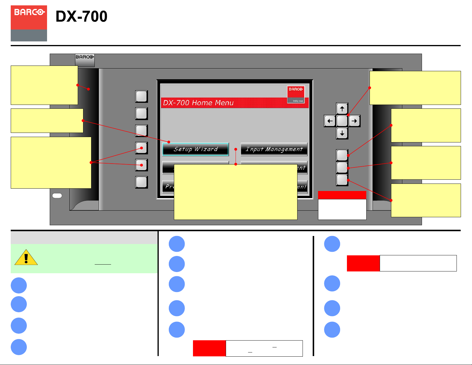
Handles
Two recessed handles are
provided. Chassis weight
depends on the number of
modules installed.
Focus
The cyan “focus” can be moved
with the Navigation buttons.
Softkeys
Six softkeys activate functions or
access menus. Softkey labels
appear in the Touch Screen’s left-
hand column. To operate, press
the Touch Screen button, or the
adjacent softkey.
Quick System Setup
The following list summarizes the
overall DX-700 setup procedure. For
error-free installation, always
the listed section in the User’s Guide.
Install and Cable LED Walls — Ensure that your LED
wall(s) are properly installed and cabled.
1
Rackmount DX-700 — Ensure that the DX-700 is
properly installed in your equipment rack.
2
(Chapter 3, “Rack-Mount Installation”)
Configure DX-700 Modules — Ensure that all
modules are installed in the proper configuration.
3
(Chapter 2, “Module Installation and Configuration”)
Connect Sources and Signals — Ensure that all
sources and signals are properly connected.
4
(Chapter 3, “Signal Installation”)
refer to
Touch Screen
There are 3 ways to use the Touch Screen:
1) Press a button on the Touch Screen itself.
2) Press a softkey directly adjacent to a button in
the Touch Screen’s left-hand column.
3) Use the arrows to move the cyan “focus”
highlight. Then, press ENTER to activate.
Power On LEDs, Fiberlink — Turn on power to your
5
6
7
8
9
LED walls and Fiberlink connections.
Power On DX-700 — Turn on power to the DX-700
chassis. (Chapter 4, “Power-Up Initialization”)
Factory Reset — The first time you use a DX-700,
or after a DX-700 returns from a show, perform a
Factory Reset. (Chapter 4, “Performing a Factory
Reset”)
Calibrate Touch Screen — Adjust display brightness
and calibrate the Touch Screen. (Chapter 4, “Using
the Front Panel Display Adjust Menu”)
Run the Setup Wizard — Use the Setup Wizard to
configure LED wall outputs and “groups.” (Chapter 4,
“Using the Setup Wizard”)
IMPORTANT
Ensure that you set up all outputs and
configure all output groups.
ENTER
TEST
PAT
PRESETS
BLACK
IMPORTANT
These three buttons do
not work from within
the Setup Wizard.
Run the Input Wizard — Use the Input Wizard to
10
11
12
13
configure inputs, and assign them to LED outputs.
(Chapter 4, “Using the Input Wizard”)
IMPORTANT
Fine Tune Inputs — Use the Input Management
Menu to adjust brightness, contrast, color and more.
(Chapter 4, “Using the Input Management Menu”)
Fine Tune Displays — Use the Display Management
Menu to adjust contrast, gamma, Fiberlink and more.
(Chapter 4, “Using the Display Management Menu”)
Recall Presets — Recall the desired preset, and
you’re ready to begin production. (Chapter 4, “Using
the Preset Management Menu”)
Navigation
Use the arrows move the “focus”
highlight, and to scroll lists. To activate
a highlighted function, press ENTER.
TEST PAT
Press to access the Test
Pattern Menu, to assign test
patterns to selected outputs.
PRESETS
Press to access the Preset
Management Menu, to recall
and manage presets.
BLACK
Press to take all outputs to
black. Press again to restore
the previous video.
Ensure that you save a preset after
you configure each input.
P/N 26-0601004-00, Rev 02
Page 2
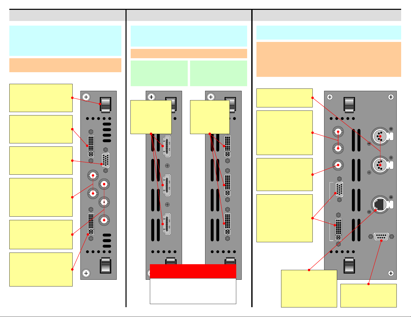
System ModuleOutput ModulesInput Module
DX-700 Input Modules provide the system’s input,
scaling, and mixing functions. Within each module, the
input source is selected from among the various input
connectors and scaled to the required size and position
in the final display.
• Use the Input Wizard to configure inputs.
• Use the Input Management Menu to fine tune inputs.
Latches
Used for precise insertion and
removal. See the “Module
Insertion and Removal” section.
Expansion Out
Connects input modules for
external and cross-bank
stacking configurations only.
EXP OUT DVI / EXP IN
RGBHV Input
Accepts RGBHV inputs up to
QXGA (2048 x 1536), with a
max. 240 MHz pixel clock.
1 -HD/SDI -2
HD / SDI Input
Accepts:
• 2 x SDI
• 2 x HD-SDI
• 1 x SDI and 1 x HD-SDI
• 1 x Dual HD-SDI
Component Input
Accepts Composite, S-Video
and Component. See the
“Format Connection Table.”
Each module provides three outputs, which can drive one
(or more) attached displays from any portion of a selected
source image.
• Use the Setup Wizard to configure outputs and groups.
NNI Output Module
Runs next generation LEDs.
Each output is limited to
1024 x 768 pixels.
DVI Output Module
Runs legacy LEDs. Each
output is limited to
800 x 600 pixels.
The System module provides connections for Ethernet, synchronization
(genlock), monitoring, DMX and diagnostics.
Under the DX-700 Management Menu:
• Use the Ethernet Menu to configure Ethernet parameters.
• Use the Monitor Setup Menu to set monitor output parameters, test patterns, and
the monitor’s video source.
• Use the Genlock Menu to set the master sync source, and individual bank
genlock sources.
DMX Control
Currently not implemented.
LED Outputs
Three HDMI-type
connectors are
provided for NNI
outputs.
LED OUT 1 LED OUT 2 LED OUT 3
RGBHV
LED Outputs
Three DVI-I type
connectors are
provided for DVI
outputs.
LED OUT 1 LED OUT 2 LED OUT 3
Genlock Inputs
• Single: connect
composite sync or
black burst to H/CS IN.
• Separate: connect H
and V sync to H/CS IN
and V IN.
GENLOCK EXP
V INH / CS IN LOCK
Expansion Lock Out
Y / COMP C / Pb Pr
For external stacking
configurations, provides
sync and communications
to additional DX-700s.
RGBHV Monitor Out
MONITOR
DVI Monitor Out
Use the Monitor Output
Menu to set resoluti on and
video source. Both outputs
show the same video.
DIAGNOSTICETHERNETDMX THRUDMX IN
DVI / Expansion Input
Accepts single or dual DVI
inputs, with resolutions up to
QXGA (2048 x 1536) with a
max. 240 MHz pixel clock.
WARNING
Output Module connectors use proprietary
signals and pinouts. Do not connect the
outputs to anything other than the inputs of
Barco LED tiles.
Ethernet
100BaseT connection for
Director Toolset
communications. Use the
Ethernet Menu to set
parameters.
Diagnostic Port
For factory and technical
support use only.
Page 3

DX-700 Module Insertion
Ensure that DX-700 power is off.
Carefully insert the module, and push it into the
3
chassis until the module’s top latch stops
against the chassis.
5
Simultaneously push both latches towards the
center of the module, until the module is fully
seated against the chassis.
1
Orient the module so that the power connector is
2
at the bottom.
Rear View:
• System Module
• Input Module
• Output Modules
Retaining Screw
Latch
Chassis
CAUTION
Always push both latches
simultaneously.
Note
The rear panels of all
three DX-700
modules are identical.
Power
Connector
Insert module
until the latch
stops against
the chassis
Raise the top latch until you can slide the module
4
Raise latch, slide
module farther in,
against pivot point
farther into the chassis — up to the latch’s pivot point.
until it stops
Module
Pivot
Point
Simultaneously push both
latches toward the center
of the module
6
Tighten both retaining screws to secure the
module.
DX-700 Module Removal
1
Ensure that DX-700 power is off.
2
Loosen both retaining screws on the module.
3
Simultaneously push both latches away from the
center of the module.
CAUTION
Always push both latches
simultaneously.
4
When both latches are clear of the chassis,
remove the module.
Page 4

DX-700 Module Configuration Rules
DX-700 supports a wide number of system configurations. Input and output modules are installed in
“banks,” consisting of one (or more) input modules, and either one or two output modules (with two
being the maximum allowed in a bank). By definition, a “bank” is a way of combining inputs and
outputs into independent video processors that are capable of driving one (or more) LED walls.
In multi-bank configurations, all banks must be directly adjacent to one another, with no
4
blank panels in between.
Bank 2Bank 1
Bank 2Bank 1
Please remember the following important “module” configuration rules.
In the most basic of DX-700 “single bank” configurations, you must have at least one input
1
module and one output module — to route video to an LED wall.
As you face the rear of the chassis, the right-most module in the Input/Output Section must
2
always be an Output Module. It must always be right-justified against the System Module.
Input / Output Section Input / Output Section
Input
Input
Blank
Blank
Blank
Correct Justificat io n
Input
Output
System
Power
Blank
Input
Blank
Incorrect Justification
Within any bank, all modules must be adjacent to each other, with no blank panels
3
in-between, and all Output Module(s) are always right-justified.
Bank 1 Bank 1
Input
Blank
Blank
Blank
Input
Output
Output
System
Power
Input
Blank
Blank
Input
Input
Input
Output
Output
Blank
Blank
Output
System
System
Power
Power
Blank
IMPORTANT
1
2
3
Input
Input
Input
Input
Output
Correct Justification
With the exception of “spare” modules, if the DX-700 determines that any
modules are incorrectly installed (or missing), a Startup Diagnostic Menu
appears which prompts you to power down and re-configure your modules.
If the above prompt occurs, and provided that a System Module is properly
installed, on the Startup Diagnostic Menu you can press the DX-700
Management button, and access a subset of management functions.
The DX-700 will not recognize modules that are installed to the left of a blank
panel. They will be treated as spares.
Slots that do not contain modules must always have blank panels installed.
Output
System
Power
Storing Spare Modules
Configure a bank according to the rules
outlined in the “DX-700 Module
Configuration Rules” section.
Install a blank panel immediately to the
left of the bank’s left-most input
module.
In the remaining slots, insert spare
modules. These are ignored and
treated as spares.
Input
Input
Input
Input
Blank
Output
Incorrect Justification
Blank
Output
Input
Bank 1Spares
Input
Input
Input
Output
Output
System
System
Power
Power
Correct Justificat io n
Incorrect Justification
DX-700 User’s Guide
For complete details on all installation, setup, configuration and operations procedures, please refer to
the DX-700 User’s Guide.
Format Connection Table
Use the following table to connect various source formats to the DX-700, using the system’s
Component input (3 x BNC) on the Input Module.
Input
Connector
Y / COMP
C / P
b
P
r
Composite
Video
S-Video
(Y/C)
(Luma) (Luma) (G)
(Chroma) (Pb) (B)
YUV
(YP
(Pr) (R)
)
bPr
Sync on Green
RGB
P/N 26-0601004-00, Rev 02
 Loading...