

Page 1

Cooling liquid refill
Installation manual
For XLM, DP90 and DP100
R59770032/00
24/08/2006
Page 2

Barco nv Events
aan 5, B-8520 Kuurne
Noordl
Phone: +32 56.36.89.70
Fax: +32 56.36.88.24
sales.events@barco.com
E-mail:
Visit us at the web: www.barco.com
PrintedinBelgium
Page 3
1. About the cooling circuit and cooling liquid
1. ABOUT THE COOLING CIRCUIT AND COOLING
LIQUID
1.1 Overview of the Cooling circuit
Cooling circuit flow and parts
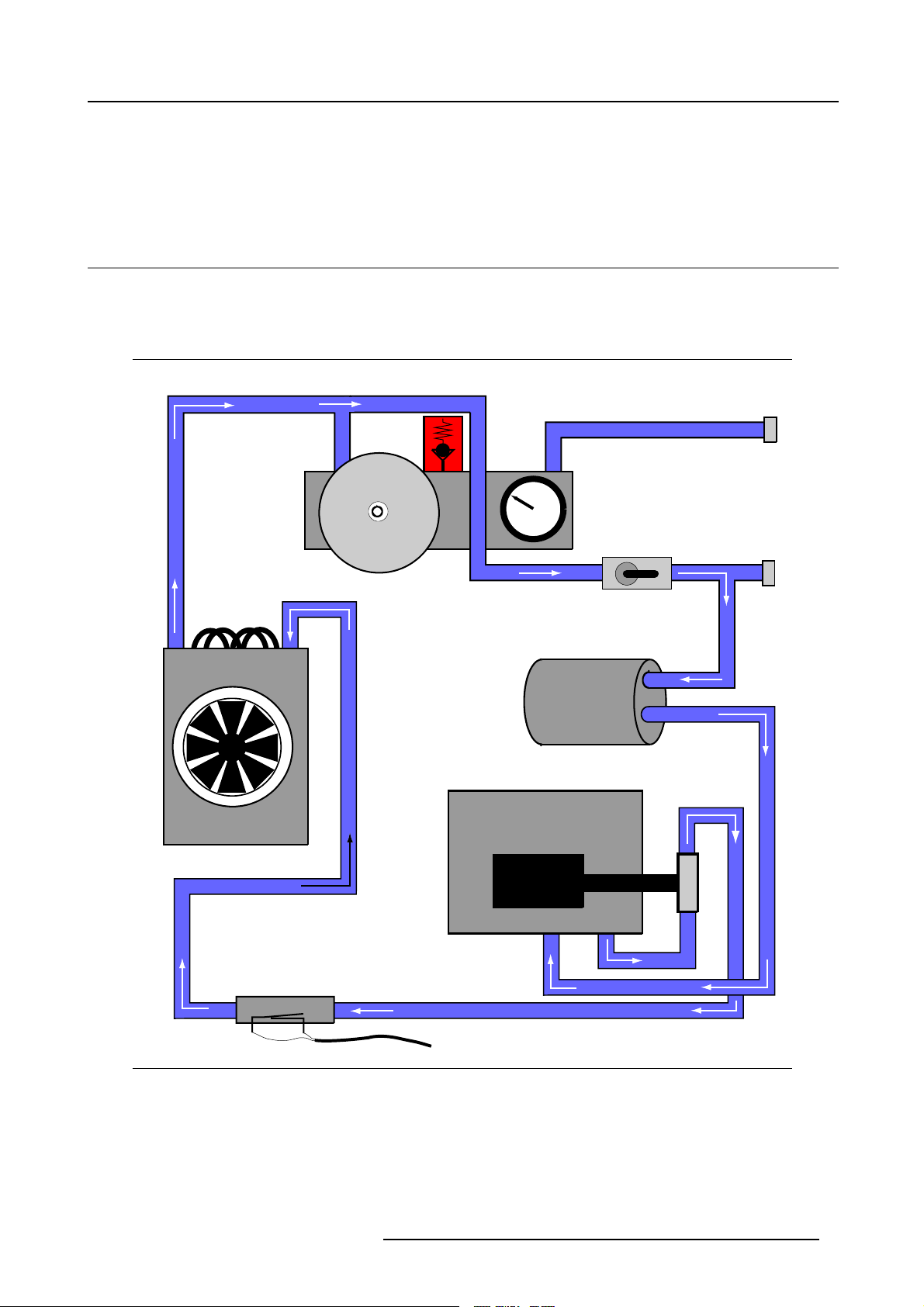
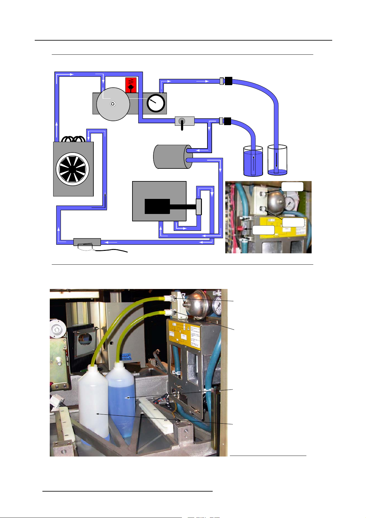
During operation, a closed loop of flexible tubing circulates cooling liquid to critical components, such as the engine and to the
integrator rod entry. The cooling circuit flow, during operation, is represented in diagram b elow:
The liquid cooling loop
Pressure relief
valve (3 Bar)
Manometer
Outlet
Heat
Exchanger
Waterflow Sensor
Expansion Vat
Engine
Pump
Vane
Inlet
Light Pipe
entry
to SMPS Control
Image 1-1
Cooling circuit flow
Cooling liquid Info
Over time the coo
To maintain sound cooling properties, we advise ANNUAL replacement o f the cooling liquid.
R59770032 COOLING LIQUID REFILL 24/08/2006
ling liquid may show deterioration and hence less effective cooling characteristics.
1
Page 4
1. About the cooling circuit and cooling liquid
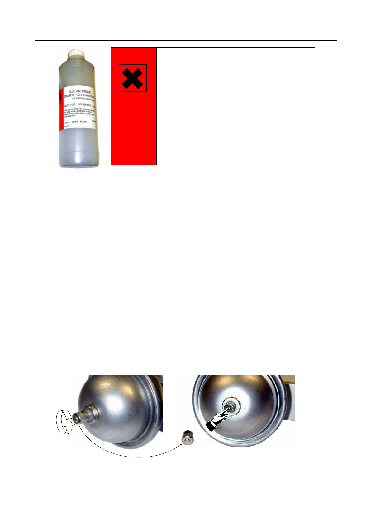
BLUE ANTIFREEZE
DILUTED 1,2 ETHANEDIOL
(1/3 ETHANEDIOL-2/3 DEMI WATER)
HARMFUL
Image 1-2
Safety label
Before ope ning the bottles with fresh cooling liquid, attentively read the safety instruction mentioned on the bottle label and listed
below.
Handling the cooling liquid
NOT FOR HOUSEHOLD USE
KEEP OUT OF REACH OF CHILDREN. HARMFUL
BY ORAL INTAKE. AVOID EXPOSURE TO
PREGNANT WOMEN. AVOID CONTACT WITH
EYES AND SKIN
BARCO KUURNE BELGIUM
R821679
1000ml
• Avoid contact of the liquid with Eyes, Skin and Clothing.
• Avoid inhale of the no xious fumes.
• Conserve the product in the original package a nd on a good ventila ted room.
Personal protection rules
• Handle the cooling liquid in a good ventilated room.
• Under no circumstances eat, drink and smoke while handling the liquid.
• Wear gloves (Butylrubber, PVC....) and Goggles.
• Wear suitable protection clothing.
1.2 Preparation of the projector
What has to be done?
1. Switch Off the projector. (see owners or installation manual of the projector)
2. Removethesidecover.
3. Remove the lamp unit to access the cooling liquid In- and Outlet.
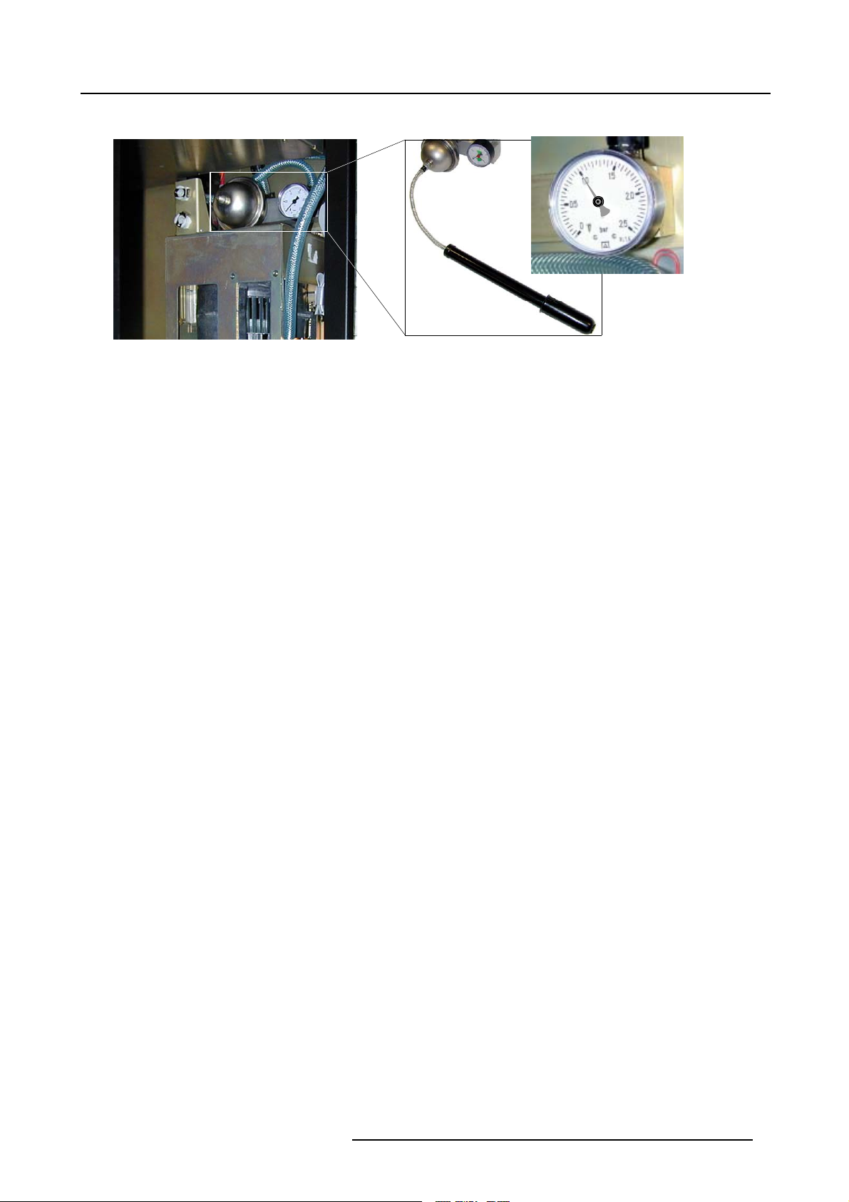
4. Remove the screw cap on the valve of the pressure vat and press the air release valve to release the expansion vat pressure.
Image 1-3
Expansion vat pressure release
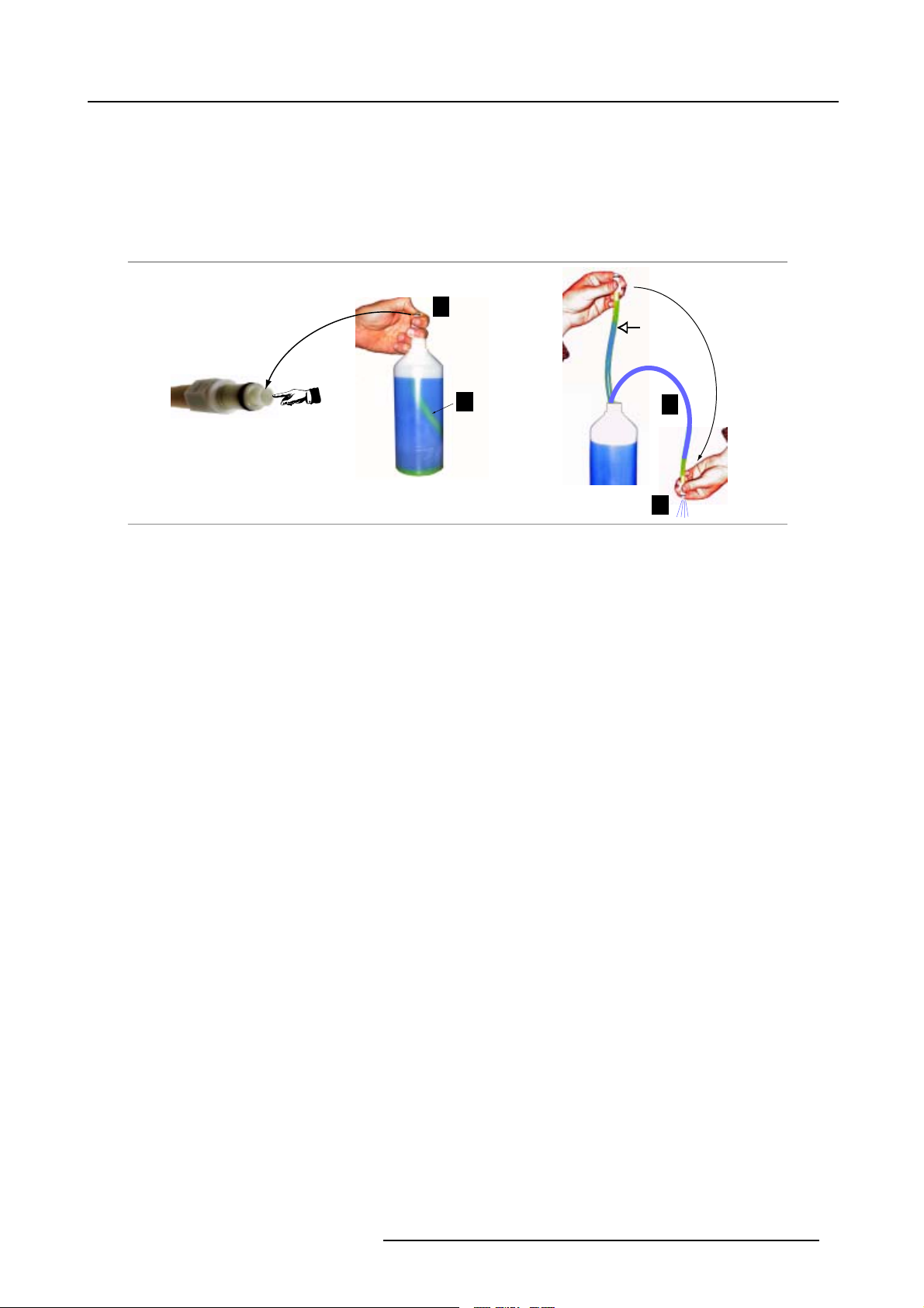
5. It is advisable to fill the tube of the pump s uct ion side with liquid prior to start-up. Proceed as follows:
2
R59770032 COOLING LIQUID REFILL 24/08/2006
Page 5
1. About the cooling circuit and cooling liquid
- Immerse the inlet tube e nd without fitting as far as possible into the bottle with fresh cooling liquid (1).
- Open the fitting by pressing-in valve mechanism (2) to allow filling the immersed tubing with liquid.
- Release valve to trap the liquid in the tube.
- Drop the fitting below the liquid level (3).
- Redo valve opening in fitting by pressing-in valve mechanism and allow the liquid to fill the tube (4).
- Release valve mechanism once all air is expelled.
- Remove the inlet tube out of bottle.
The liquid cooling loop - Filling the Inlet tubing
2
Valved Straight-Through
Fitting
1
Image 1-4
Filling the inlet tubing
6. Proceed with liquid cooling replacement or liquid cooling refilling.
3
4
R59770032 COOLING LIQUID REFILL 24/08/2006
3
Page 6

1. About the cooling circuit and cooling liquid
4 R59770032 COOLING LIQUID REFILL 24/08/2006
Page 7
2. Replacement of the cooling liquid
2. REPLACEMENT OF THE COOLING LIQUID
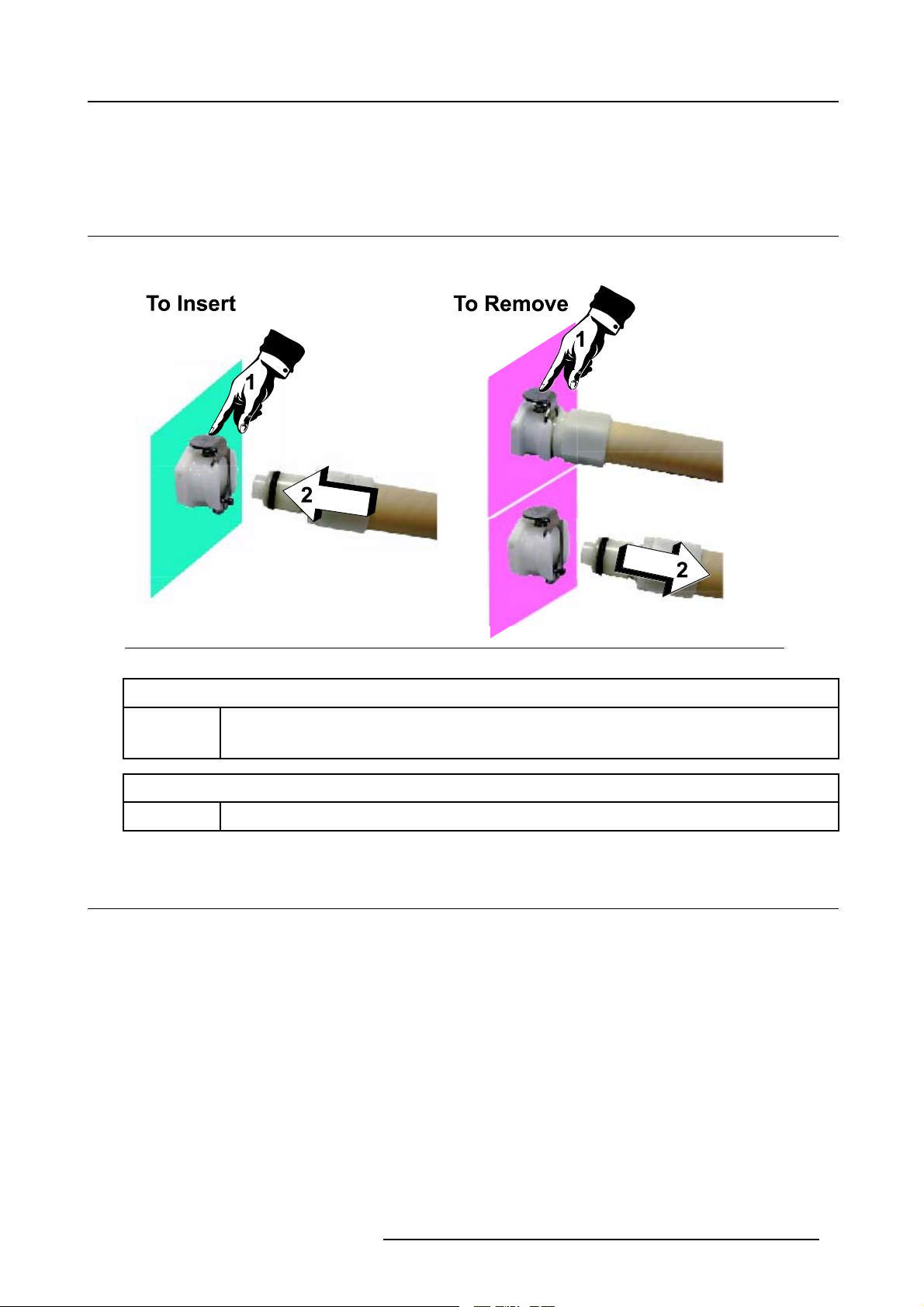
2.1 Insertion/Removing valved fitting
How to handle
Image 2-1
Insertion/Removing hose connectors
Insertion
To avoid damage to the connector seal, always depress connector tab (1) prior to inserting (2).
This prevents damage caused by forcing the gask
Removing
Depress connector tab (1) and remove the valved fitting (2).
2.2 Cooling liquid replacement
How to replace
1. CLOSE THE VANE.
et end into a closed connector. Listen for a “click”.
R59770032 COOLING LIQUID REFILL 24/08/2006
5
Page 8
2. Replacement of the cooling liquid
The liquid cooling loop - Replacement of liquid
Heat
Exchanger
Waterflow Sensor
Expansion Vat
Engine
Pressure relief
valve (3 Bar)
Pump
Manometer
Vane
Light Pipe
entry
Outlet
Inlet
Outlet
Inlet
Vane
Image 2-2
Replacement of the cooling liquid (Principle)
to SMPS Control
Outlet
Inlet
Bottle filled with fresh
cooling liquid
Bottle filled with a few
cooling liquid
Image 2-3
Replacement of the cooling liquid (in practice)
6 R59770032 COOLING LIQUID REFILL 24/08/2006
Page 9

2. Replacement of the cooling liquid
2. Push the valvedfittingo f the filled tube into theInlet’IN’ of the cooling circuit. Ensure the loose end of thetuberemains immersed
in the liquid.
3. First, immerse the loose end of the other tube into the a bottle filled with a little liquid, to prevent the inlet tube from draining, and
next push the valved fitting into the Outlet ’OUT’ of the cooling circuit.
4. Switch on the projector. After projector boot-up procedure, the internal pump will automatically start sucking-up the fresh liquid
supply and expelling aged liquid into the empty bottle.
5. Timely switch Off the projector to prevent the fresh liquid level dropping below the free tube inlet. This again to avoid unwanted
air being sucked into the cooling loop.
6. Continue with the procedure for expelling unwanted air.
2.3 Expelling of any unwanted air
Expelling of any unwanted air
1. Close the vane, if not yet closed.
2. Put the free tube inlet of the tube connected to the ’OUT’ outlet into the remaining fresh liquid.
The liquid cooling loop - Expelling air bubbles
Heat
Exchanger
Waterflow Sensor
Expansion Vat
Engine
Pressure relief
valve (3 Bar)
Pump
Manometer
Vane
Outlet
Inlet
Light Pipe
entry
to SMPS Control
Image 2-4
Unwanted bubbles expelling (principle)
R59770032 COOLING LIQUID REFILL 24/08/2006 7
Page 10

2. Replacement of the cooling liquid
Outlet
Inlet
Bottle filled with fresh
cooling liquid
Image 2-5
Unwanted bubbles expelling (in practice)
3. Switch On the projector. Via circulation any unwanted air bubbles will be expelled.
Tip: Let circulate for 10 minutes, opening and closing the vane at intervals of 2–minutes (This expels any accumulated air
in and around the vane).
4. Switch Off the projector.
5. Check the transparent inspection tube. No air should be present in this tube.
Transparant
Inspection
Tube
Image 2-6
Transparent tube
6. Disconnect tubes from In- and Outlet cooling loop.
Note: Removing the tube fittings from the In- Outlet of the cooling loop brings about liquid spilling. Always clean spilled liquid.
7. OPEN THE VANE.
8
R59770032 COOLING LIQUID REFILL 24/08/2006
Page 11
8. Pressure cooling loop to 1 Bar, using appropriate air pump and adapter.
Image 2-7
Pressurizing expansion vat
2. Replacement of the cooling liquid
OK
R59770032 COOLING LIQUID REFILL 24/08/2006 9
Page 12

2. Replacement of the cooling liquid
10 R59770032 COOLING LIQUID REFILL 24/08/2006
Page 13

3. Liquid Cooling Refilling, expelling air
3. LIQUID COOLING REFILLING, EXPELLING AIR
3.1 Refilling, expelling air
When?
Minor drops in pressure over time are to be expected. Once the minimum pressure of 0.5 bar is reached, proceed with refilling
procedure.
Max
Min
Image 3-1
Manometer read out
Procedure to follow
• Prepare the projector ("Preparation of the projector", page 2 ).
• Expel the unwanted air in the cooling circuit ("Expelling of any unwanted air", page 7 ).
• Pressure cooling loop to maximum 1 bar, using ap propriate air pump and adapter
OK
R59770032 COOLING LIQUID REFILL 24/08/2006
11
 Loading...