

Page 1

DP2K-E series
R5906693/01
19/06/2015
User and installation manual
Page 2

Barco Visual (Beijing) Electronics Co., Ltd
地址:北京市 昌平区 中关村科技园 昌平园 昌盛路 16号
Phone: +86 10 8010 1166
Fax: +86 10 8970 2793
Support: www.barco.com/en/support
Visit us at the web: www.barco.com
Barco NV
President Kennedypark 35, 8500 Kortrijk, Belgium
Phone: +32 56.36.82.11
Fax: +32 56.36.883.86
Support: www.barco.com/en/support
Visit us at the web: www.barco.com
Printed in Belgium
Page 3

Changes
Barco provides this manual ’as is’ without warranty of any kind, either expressed or implied, including but not limited to the implied warranties or m erchantability and fitness for a particular purpose. Barco may make improvements and/or changes to the product(s) and/or the
program(s) described in this publication at any time without notice.
This publication could c ontain technical inaccuracies or typographical errors. Changes are periodically made to the information in this
publication; these changes are incorporated in new editions of this publication.
The latest edition of Barco manuals can be downloaded from the Barco web site w
h
ttps://www.barco.com/en/signin.
ww.barco.com or from the secured Barco web site
Copyright ©
All rights reserved. No part of this document may be copied, reproduced or translated. It shall not otherwise be recorded, transmitted or
stored in a retrieval system without the prior written consent of Barco.
Federal Communications Commis sion (FCC Statement)
This equipment has been tested and found to comply with the limits for a class A digital device, pursuant to Part 15 of the FCC rules.
These limits are designed to provide reasonable protection aga inst harmful interference when the equipment is operated in a commercial
environment. This equipment generates, uses, and can radiate radio frequency energy and, if not installed and used in accordance with
the instruction m anual, may cause harmful interference to radio communications. Operation of this equipment in a residential area may
cause harmful interference, in which case the user will be responsible for correcting any interference at his own expense
Changes or modifications not expressly approved by the party responsible for compliance could void the user’s authority to operate the
equipment
EN55022/CISPR22 Class A ITE (Information Technology Equipment)
Class A ITE is a category of all other ITE which satisfies the class A IT
be restricted in its sale but the following warning shall be included in the instructions for use:
Warning : This is a class A product. In a dom estic environment this product may cause radio interference in which case the user may be
required to take adequate measures.
E limits but not the class B ITE limits. Such equipment should not
Guarantee and Compensation
Barco provides a guarantee relating to perfect manufacturing as part of the legally stipulated terms of guarantee. On receipt, the purchaser
must immediately inspect all delivered goods for damage inc urred during transport, as well as for material and manufacturing faults Barco
must be informed immediately in writing of any complaints.
The period of guarantee begins on the date of transfer of risks, in the case of special systems and software on the date of commissioning,
at latest 30 days after the transfer of risks. In the event of justified notice of complaint, Barco can repair the fault or provide a replacement
at its own discretion within an appropriate period. If this measure proves to be impossible o r unsuccessful, the purchaser can demand a
reduction in the purchase price or cancellation of the contract. All other claims, in particular those relating to compensation for direct or
indirect damage, and also damage attributed to the operation of software as well as to other services provided by Barco, b eing a component
of the system or independent service, will be deemed invalid provided the dam age is not proven to be attributed to the absence of properties
guaranteed in writing or due to the intent or gross negligence or part of Barco.
If the purchaser or a third party carries ou
in particular if the systems are o perated incorrectly or if, after the transfer o f risks, the goods are subjec t to influences not agreed upon in
the contract, all guarantee claims of the purchaser will be rendered invalid. Not included in the guarantee co verage are system failures
which are attributed to programs or spe
maintenance are n ot subject to the guarantee provided by Barco either.
The environmental conditions as well as the servicing and m aintenance regulations specified in this manual m ust be complied with by the
customer.
t modifications or repairs on goods delivered by Barco, or if the goods ar e handled incorrectly,
cial electronic circuitry provided by the purchaser, e.g. interfaces. Normal wear as well as normal
Software License Agreement
You should carefully read the following terms and conditions before u sing this software. Your use of this software indicates your acceptance
of this license agreement and warranty.
Terms and Conditions:
1. No redistribution of the software is allowed.
2. Reverse-Engineering. You m ay not reverse engineer, decompile, disassemble or alter this software product.
Disclaimer of Warranty:
This software and the accompanying files are sold “as is” and without warranties as to performance or merchantability or any other warranties whether expressed or im plied. In no event shall Barco be liable for damage of any kind, loss of data, loss of profits, business
Page 4

interruption or o ther pecuniary loss arising directly or indirectly. Any liability of the seller will be exclusively limited to replacement of the
product or refund of purchase price.
GNU-GPL code
If you would like a copy of the GPL source code contained in this product shipped to you on C D, p lease contact Barco. T he cos t of preparing
and mailing a CD will be charged.
Trademarks
Brand and product names mentioned in this manual may be t rademarks, registered trademarks or copyrights of their respective holders.
All brand and product names mentioned in this manual serve as commen ts or examples and are not to be understood as advertising for
the products or their m anufacturers.
Page 5

Table of contents
TABLE OF CONTENTS
1. Welcome ......... ................ ................ ................ .................. ................ ................ .. 3
1.1 About this manual . . .................................................................................................................. 4
2. Safety................................................................................................................. 5
2.1 General considerations ............................................................................................................... 6
2.2 Important safety instructions ......................................................................................................... 7
2.3 Product safety labels ................................................................................................................10
2.4 Light beam Hazard Distance (HD) .................................................................................................. 11
2.5 HD in function of the lens Throw Ratio (TR)........................................................................................ 13
3. Getting started ................ ................ ................ ................ ................ ................ .....15
3.1 Installation requirements .. . .........................................................................................................16
3.2 Unpacking the projector .............................................................................................................18
3.3 Initial inspection......................................................................................................................20
4. Installation process ...............................................................................................21
4.1 Installation process overview........................................................................................................ 22
5. Physical installation ..............................................................................................23
5.1 Positioning the DP2K-E series projector at port window ...........................................................................24
5.2 Connecting the projector with the power net .......................................................................................27
5.3 Connecting a UPS to the projector electronics . . ................................................................................... 28
6. Lenses & Lens selection .........................................................................................31
6.1 Available lenses ..................................................................................................................... 32
6.2 Lens selec tion .......................................................................................................................33
6.3 Lens installation .....................................................................................................................34
6.4 Lens removal ........................................................................................................................35
6.5 Lens shift, zoom & focus . . .......................................................................................................... 36
7. Input & Communication..........................................................................................39
7.1 Introduction ..........................................................................................................................40
7.2 Local Keypad ........................................................................................................................41
7.3 ProjectorStatus......................................................................................................................43
7.4 Cinema Controller ................................................................................................................... 45
8. ICMP ........ ................ ................ ................ .................. ................ ................ .......47
8.1 ICMP introduction. . . .................................................................................................................48
8.2 ICMP HDD ........................................................................................................................... 50
8.3 ICMP communication ports ......................................................................................................... 51
8.4 ICMP s ource input ports............................................................................................................. 53
8.5 ICMP reset button and status LEDs ................................................................................................58
8.6 ICMP HDD status LEDs ............................................................................................................. 59
8.7 ICMP device certificate..............................................................................................................61
8.8 ICMP configuration via Communicator .............................................................................................63
8.9 Obtaining the Barco ICMP certificate ...............................................................................................64
8.10 Removing a HDD form the ICMP ...................................................................................................65
8.11 Installing a HDD into the ICMP......................................................................................................66
9. Communicator Touch Panel.............. .................. ................ ................ ................ .....69
9.1 Communicator Touch Panel.........................................................................................................70
9.2 Installing the Touch Panel interface.................................................................................................72
9.3 Repositioning the Touch Panel interface . . . ........................................................................................ 74
10. Starting up... .................. ................ ................ ................ ................ ................ .....75
10.1 Switching the DP2K-E series projector ON.........................................................................................76
10.2 Switching the DP2K-E series projector OFF........................................................................................77
11. Scheimpflug........................................................................................................79
11.1 Scheimpflug introduction .. . .........................................................................................................80
11.2 Scheimpflug adjustment.............................................................................................................82
11.3 Fixation of the Lens Holder front plate ..............................................................................................84
11.4 Back Fo cal Length adjustment ......................................................................................................86
12. Convergence ............ ................ ................ ................ ................ .................. .........91
12.1 Convergence controls ............................................................................................................... 92
12.2 Preparing for convergence adjustme nt . . . . .........................................................................................94
12.3 Converging the bluepattern onto the red pattern ..................................................................................96
12.4 Converging the green pattern onto the redpattern................................................................................. 97
12.5 Closing off the Light Processor compartment . .....................................................................................98
13. Lamp House. ................ ................ ................ ................ ................ .................. .....99
13.1 Introduction .........................................................................................................................100
13.2 Removal of the Lamp Module ......................................................................................................101
R5906693 DP2K-E SERIES 19/06/2015
1
Page 6

Table of contents
13.3 Installation of the Lamp House .....................................................................................................103
13.4 Resetting the lamp parameters . . . .................................................................................................105
14. Preventative maintenance actions ...... ................ ................ ................ ................ ..... 107
14.1 1 month maintenance actions......................................................................................................108
14.2 3 month maintenance actions......................................................................................................109
15. Maintenance procedures................ ................ ................ ................ ................ ........111
15.1 Check the dust fi lters...............................................................................................................112
15.2 Vacuum cleaning of the dus t filters ................................................................................................113
15.3 Washing and drying the dust filters ................................................................................................114
15.4 Cleaning the lens . . . ................................................................................................................115
15.5 Cleaning the exterior of the projector ..............................................................................................116
15.6 Authorization to clear security warning on the projector ..........................................................................117
16. Removal and installation of the projector covers .. ................ ................ ................ ....... 119
16.1 Removal of the front cover .........................................................................................................120
16.2 Removal of the rear cover..........................................................................................................121
16.3 Removal of the top cover...........................................................................................................122
16.4 Removal of the left sidecover......................................................................................................123
16.5 Removal of the right side cover ....................................................................................................125
16.6 Removal of the top cover plate ofthe Light Processor compartment.............................................................126
16.7 Removal of the side cover plate of the Light Processor compartment ...........................................................127
16.8 Installation of the side cover plate of the Light P rocessor compartment .........................................................128
16.9 Installation of the top cover plate of the Light Process or compartment...........................................................129
16.10 Installation of the right side cover..................................................................................................130
16.11 Installationof the left side cover ...................................................................................................131
16.12 Installation of the top cover.........................................................................................................133
16.13 Installation of the rear cover........................................................................................................134
16.14 Installation of the front cover.......................................................................................................135
17. Specifications.................................................................................................... 137
17.1 Specifications of the DP2K-6E .....................................................................................................138
17.2 Specifications of the ICMP .........................................................................................................140
17.3 Dimensions of the DP2K-Eseries projector.......................................................................................142
17.4 Dimensions of the universal pedestal..............................................................................................143
17.5 Technical Regulations ..............................................................................................................144
18. Pin configurations.......... ................ ................ ................ ................ ................ ..... 145
18.1 About G eneral Purpose Inputs & Outputs (GPIO).................................................................................146
18.2 Pin configurations of the Cinema Controller communication ports ...............................................................148
18.3 Pin configurations of the ICMP communication ports .............................................................................149
19. Environmental information.................................................................................... 153
19.1 Disposal information................................................................................................................154
19.2 RoHS compliance ..................................................................................................................155
19.3 Hazards.............................................................................................................................157
19.4 Production address . ................................................................................................................158
19.5 Importers contact information ......................................................................................................159
2
R5906693 DP2K-E SERIES 19/06/2015
Page 7

1. Welcome
1. WELCOME
Congratulations
May we congratulate you on your purchase of a Barco DP2K -E series projector! It is our sincere wish that this digital projector meets
up to your every expectation and that you thereby take a little time to page through this important manual. Familiarizing yourself
with it’s features, important safety ins tructions and necessary maintenance a ctions, will ensure you enjoy m any years of reliable,
trouble-free high quality performance.
Overview
• About this manual
R5906693 DP2K-E SERIES 19/06/2015
3
Page 8

1. Welcome
1.1 About this manual
How to use this manual?
We suggest that you read over this manual before you install and use your DP2K-E se ries projector. Inside it, you will find important
information regarding safety, installation and maintenance. We urge even the experienced user to take the necess ary time to page
through this manual. We believe everyone will benefi t from this manual. Not in the least our editors, who will sleep more comfortably
knowing their efforts have had their effect.
What’s expected from you?
For your safety and in th e interest of reliable, trouble-free, high quality performance, we urge the user/operator/service technician,
to follow all instructions precisely. Follow the maintenance recommendations and procedures in this manual step by step to keep
your projector in excellent condition. Doing so will directly impact the lifetime of your DP2K-E series projector.
If, after having read over these instructions, you ex perience difficulties, please contact your
best to assist you and get you up and running as soon as possible.
“Treat your DP2K-E series projector as your own and it will reward you with many trouble-free years of exquisite digital
entertainment pleasure!”
Barco service partner! They will do their
4
R5906693 DP2K-E SERIES 19/06/2015
Page 9

2. SAFETY
About this chapter
Read this chapter attentively. It contains important information to prevent personal injury while ins talling and using your DP2K-E series projector. F urthermore, it includes several cautions to prevent damage to your DP2K-E series projector. Ensure that you
understand and follow all safety guidelines, safety instructions and warnings mentioned in this chapter before installing and using
the DP2K-E series projector. A fter this chapter, additional “warnings” and “cautions” are given depending on the procedure. Read
and follow these “warnings” and “cautions” as well.
Clarification of the term “DP2K-E series” used in this document
When r eferring in this document to the term “DP2K-E series” means that the content is applicable for following Barco products:
•DP2K-6E
Barco provides a guarantee relating to perfect manufacturing as part of the legally stipulated terms of guarantee. Observing the specification mentioned in this chapter is critical for projector performance. Neglecting
this can result in loss of warranty.
Overview
• General considerations
• Important safety instructions
• Product safety labels
• Light beam Hazard Distance (HD)
• HD in function of the lens Throw Ratio (TR)
2. Safety
R5906693 DP2K-E SERIES 19/06/2015
5
Page 10

2. Safety
2.1 General considerations
General safety instructions
• Before operating this equipment please read this manu al thoroughly and retain it for future reference.
• Installation and preliminary adjustments should be performed by qualified Barco personnel or by authorized Barco service dealers.
• All warnings on the projector and in the doc umentation manuals should be adhered to.
• All instructions for operating and use of this equipment must be followed precisely.
• All local installation codes should be adhered to.
Notice on electrical safety
This equipment is built in accordance with the requirements o f the international safety standards IEC60950-1, EN60950-1,
UL60950-1 and CAN/CSA C22.2 No.60950-1, which are the safety standards of information technology equipment including
electrical business equipment. These safety standards impose important requirements on the us e of safet
materials and insulation, in order to protect the user or operator against risk of electric shock and energy hazard and having access
to live parts. Safety standards also impose limits to the internal and external temperature rises, radiation levels, mechanical stability
and strength, enclosure construction and protection against the risk of fire. Simulated single fau
safety of the equipment to the user even when the equipment’s normal operation fails.
lt condition testing ensures the
Users definition
Throughout this manual, the terms SERVICE PERSONNEL and TRAINED PROJE CTIONIST refers to persons having appropriate
technical training and experience necessary to be knowledgeable of potential hazards to which they are exposed (including, but not
limited to HIGH VOLTAGE ELECTRIC and ELECTRONIC CIRCUITRY and HIGH BRIGHTNESS PROJECTORS) in performing a
task, and of measures to minimize the potential risk to thems elves or other persons. The term USER and OPERATOR refers to
any person other than SERVICE PERSON NEL or TRAIN ED PROJECTIONISTS, AUTHORIZED to operate professional projection
systems.
The TRAINED PROJECTIONISTS may only perform the maintenance task described in the U ser & Installation manual. All other
maintenance tasks and service tasks must be performed by qualified SERVICE PERSONNEL.
The DLP Cinem a Systems are intended "FOR PROFESSIONAL USE ONLY" by AUTHORIZED PERSONNEL familiar with potential
hazards associated with high voltage, high intensity light beams, ultraviolet exposure and high temperatures generated by the lamp
and associated circuits. Only qualified SERVICE PERSONNEL and TRAINED PROJECT IONISTS, know ledgeable of such risks,
are allowed to perform service functions inside the product enclosure.
y critical components,
Owner’s record
The part number and serial number are printed on a label whic
provided below. R efer to them whenever you call upon your Barco dealer regarding this produc t.
Product article number
Product serial number
Dealer
h is stuck on the respective part. Record these num bers in the spaces
6 R5906693 DP2K-E SERIES 19/06/2015
Page 11

2.2 Important safety instructions
To prevent the risk of electrical shock
• This projector should be operated from an AC power source. E nsure that the mains voltage and capacity matches the projector
electrical ratings. If you are unable to install the AC requirements, contact your electrician. Do not defeat the purpose of the
grounding.
• Installation according to the local electrical c ode and regulations by qualified technical personnel only.
• A readily accessible disconnect device must be incorporated externally to the equipment for removal of the power to the pr ojector cord.
• Warning: High leakage current. Earth connection essential before connecting supply.
• Do not allow anything to rest on the power cord. Do not locate this projector where persons will walk on the cord.
• Do not op erate the projector with a damaged cord or if the projector has been dropped or damaged - until it has been examined
and approved for operation by a qualified service te chnician.
• Position the cord so that it will not be tripped over, pulled, or contact hot surfaces.
• If an extension cord is necessary, a cord with a current rating at least equal to that of the projector should be used . A cord rated
for less amperage than the projector may overheat.
• Never push objects of any kind into this projector through cabinet slots as they may touch dangerous voltage points or short
circuit parts that could result in a risk of fire or electrical shock.
• Do not expose this projector to rain or moisture.
• Do not immerse or expose this projector in w ater or other liquids.
• Do not spill liquid of any kind on this projector.
• Should any liquid or solid object fall into the cabinet, unplug the set and have it checked by qualified service personnel before
resuming operations.
• Do not disassemble this projector, always take it to a trained service person when service or repair work is required.
• Do not use an accessory attachm ent which is not recommended by the m anufacturer.
• Lightning - For added protection for this video product during a lightning storm, or when it is left unattended and unused for
long periods of time, remove all power from the projector. This will prevent damage to the projector due to lightning and AC
power-line surges.
2. Safety
R5906693 DP2K-E SERIES 19/06/2015
7
Page 12

2. Safety
To prevent personal injury
• Isolate electrically before replacing the lamp or lamp house. Caution: Hot lamp (house).
• Caution: High pressure lam p may explode if improperly handled. Refer servicing to qualified service personnel.
• To prevent injury and physical damage, always read this manual and all labels on the s ystem before inserting the lamp casing,
powering the projector or adjusting the projector.
• To prevent injury, take note of the weight of the projector. Minimum 4 adult persons are needed to carry the projector.
• To prevent injury, ensure that the lens and all cover plates are c orrectly installed. See installation procedures.
• Warning: high intensity light beam. NEVER look into the lens ! High luminance could result in damage to the eye.
• Warning: extremely high brightness lamps: This projector uses extremely high brightness lamps. Never attempt to look
directly into the lens or at the lamp. If the pr ojection distance is less than 6 meter, any person needs to be at least 4 meters
away from the projected image. Avoid close range reflection of the projected image on a ny reflecting surface (such as glass,
metal, …) . When operating the projector, we strongly recommend wearing suitable safety g lasses.
• Before attempting to remove any of the projector’s covers, disconnect the projector power cord for removal of all power from
the projector.
• When required to remove all power from the projector, to access parts inside, always disconnect the projector power cord for
removal of all power from the projector.
• Do not place this equipment on an unstable cart, stand, or table. The product may fall, causing serious damage to i
possible injury to the user.
• It is hazardous to operate without lens or shield. Lenses, shields or ultra violet screens shall be changed if they have become
visibly damaged to such an extent that their effectiveness is im paired. For example by cracks or deep scratches.
• Warning: Protection from ultraviolet radiation: Do not look directly in the light beam. T he lamp contained in this p roduct is
an intense source of light and heat. One component of the light emitted from this lamp is ultraviolet light. Potential eye and skin
hazards are present when the lamp is energized due to ultraviolet radiation. Avoid unnecessary exposure. Protect yourself and
your employees by ma king them aware of the hazards and how to protect themselves. Protecting the skin c an be accomplished
by wearing tightly woven garments and gloves. Protecting the eyes from UV c an be accomplished by wearing safety glasses
that are designed to provide UV protection. In addition to the UV, the visible light from the lamp is intense and should also be
considered when choosing protective eye wear.
• Mercury Vapor Warnings: Keep the following warnings in mind when using the projector. The lamp used in t he projector
contains mercury. In case of a lamp rupture, explosion there will be a mercury vapor emission. In order to minimize the potential
risk of inhaling mercury vapors:
- Ensure the projector is installed only in ventilated rooms.
- Replace the lamp module before th e end of its operational life.
- Promptly ventilate the room after a lamp rupture, explosion has occurred, evacuate the room (particularly in case of a pre g-
nant woman).
- Seek medical attention if unusual health conditions occur after a lamp rupture, explosion, such as headache, fatigue, short-
ness of breath, chest-tightening coughing or nausea.
• Exposure to UV radiation: Some medications are known to make individuals ex tra sensitive to UV radiation. The American
Conference of Governmental Industrial Hygienists (ACGIH)
less than 0,1 micro-watts per square centimeters of effective UV radiation. An evaluation of the workplace is advised to assure
employees are not exposed to cumulative radiation levels exceeding these government guidelines.
recommends occupational UV exposure for an-8 hour day to be
t and
To prevent fire hazard
• Do not place flamma ble or combustible materials near the projector!
• Barco large screen projection products are des igned and manufactured to meet the most stringent safety regulations. This
projector radiates heat on its external surfaces and from ventilation ducts during normal operation, which is both normal and
safe. Exposing flammable or co mbus tible materials into close proximity of this projector could result in the spontaneous ignition
of that material, resulting in a fire. For this reason, it is absolutely necessary to leave an “exclusion zone” around all external
surfaces of the projector whereby no flammable or combustible materials are present. The exclusion zone must be not less
than 40 c m (16”) for all DLP Cinem a projectors. The exclusion zone on the lens side must be at least 5 m. Do not cover the
projector or the lens with any material while the projector is in operation. Keep flam mab le and combustible materials away from
the projector at all times. Mount the projector in a well ventilated area away from sources of ignition and out of direct s un light.
Never expose the projector to rain or moisture. In the event of fi re, use sa nd, CO
water on an electrical fi re. Always have service performed on this projector by authorized B arco service personnel. Always
insist on genuine Barco replacement parts. Never use non -Barco replacement parts as they may degrade the safety of this
projector.
• Slots and openings in this equipment are provided for ventilation. To ensure reliable operation of the projector and to protect
it from overheating, these opening
projector too close to walls, or other similar surface. This projector s hould never be placed near or over a radiator or heat
register. This projector should not be placed in a built-in installation or enclosure unless proper ventilation is provided.
• Projection rooms m ust be well ventilated or cooled in order to avoid build up of heat. It is necessary to vent hot exhaust air from
console to the outside of the building.
• Let the projector cool completely before storing. Remove cord from the projector when storing.
• Heat sensitive materials should not be placed in the path of the exhaust a ir or on the lamp house.
8
s must not be blocked or covered. The openings should never be blocked by placing the
or dry powder fi re extinguishers. Never use
2
R5906693 DP2K-E SERIES 19/06/2015
Page 13

2. Safety
To prevent projector damage
• This projector has been designed for use with a specific lamp (house) type. See installation instructions for its correct type.
•Theairfilters of the projector must be cleaned or replaced on a regular basis (a "clean" booth would be m onthly-minimum).
Neglecting this could result in disrupting the air flow inside the projec tor, causing overheating. Overheating may lead to the
projector shutting down during operation.
• The projector must always b e installed in a manner which ensures free flow of air into its air inlets.
• In order to ensure that correct airflow is maintained, and that the projector complies with Electromagnetic Compatibility (EMC)
and safety requirements, it should always be operated with all of it’s covers in place.
• Slots and openings in the cabinet are provided for ventilation. To ensure r eliable operation of the product and to protect it from
overheating, these openings mus t not be blocked or covered. The openings should never be blocked by placing the p roduct
on a bed, sofa, rug, or other similar surface. This product should never be placed near or over a radiator or heat register. The
device should not be plac ed in a built-in installation or enclosure unless pro per ventilation is provided.
• Ensure that nothing can be spilled on, or dropped inside the projector. If this does ha ppen, switch off and remove all power
from the projector. Do not operate the projector again until it has been checked by qualified service pe
• Do not block the projector cooling fans or free air movem ent around the projector. Loose papers or other objects may not be
nearer to the projector than 10 cm (4") on an y side.
• Do not use this equipment near water.
• Proper operation of the projector can only be guaranteed in table mounting. It is not permitted to use the projector in another
position. See installation procedure for correct installation. A ceiling mount will be supported in the future.
• Special care for Laser Beams: Special care should be used when DLP projectors are used in the same room as hi
laser equipment. Direct or indirect hitting of a laser beam on to the lens can severely damage the Digital Mirror Devices
which case there is a loss of warranty.
• Never place the projector in direct sunlight. Sunlight on the lens can severely damage the Digital Mirror Devices
case there is a loss of warranty.
• Save the original shipping carton and packing material. They will come in handy if you ever have to ship your equipment. For
maximum protection, repack your set as it was originally packed at the factory.
• Disconnect the power to the projector before cleaning. Do not use liquid cleaners or aerosol cleaners. Use a damp cloth for
cleaning. Nev er use strong so lvents, such as thinner or benzine, or, patrol, or abrasive cleaners, since these will damage the
cabinet. Stubborn stains may be removed with a cloth lightly dampened with mild detergent solution.
• To ensure the highest optical performance and resolution, the projection lenses are specially treated with an anti-reflective
coating, therefore, avoid touching the lens. To remove dust on the lens, use a soft dry cloth. Do not use a damp cloth, detergent
solution, or thinner.
• Rated maximum ambient temperature, t
• The lamp hou se shall be replaced if it has become damaged or thermally deform ed.
• Do not stack DP2K-E series projectors.
= 35°C (95°F).
a
rsonnel.
gh power
TM
in which
TM
in
On servicing
• Do not attempt to service this product yourself, as opening or removing covers may expose you to dangerous voltage potentials
and risk of electric shock.
• Refer all s ervicing to qualified service personnel.
• Attempts to alter the factory-set internal controls or to change other control settings not specially dis cussed in this manual can
lead to permanent damage to the projector and cancellation of the warranty.
• Remove all power from the projector and refer servicing to qualified service technicians under the following conditions:
- When the power cord or plug is damaged or frayed.
- If liquid has been spilled into the equipment.
- If the product has been exposed to rain or water.
- If the product does not operate normally wh en the operating instructions are followed. Adjust only those controls that are
covered by the operating instructions since improper adjustmen
require extensive work by a qualified technician to restore the product to normal operation.
- If the product has been dropped or the cabinet has been damaged.
- If the product exhibits a distinct change in performance, indicating a need for service.
• Replacement parts: When replacement parts ar e required, be sure the service technician has used original Barco replacement
parts or authorized replacement parts whic h have the same cha racteristics as the B arco original part. Unauthorized substitutions m ay result in degraded performance and reliability, fire, electric shock or other hazards. Unauthorized substitutions may
void warranty.
• Safety check: Upon completion of any service or repairs to this projector, ask the service technician to perform safety checks
to determine that the product is in proper operating c
• Possible explosion hazard: Always keep in mind the caution below:
ondition.
t of the other controls may result in damage and will often
To prevent battery explosion
• Danger of explosion if battery is incorrectly installed.
• Replace only with the same or equivalent type recommended by the manufacturer.
• For disposal of used batteries, always consult federal, state, local and provincial hazardous waste disposal rules and regulations
to ensure proper disposal.
R5906693 DP2K-E SERIES 19/06/2015
9
Page 14
2. Safety
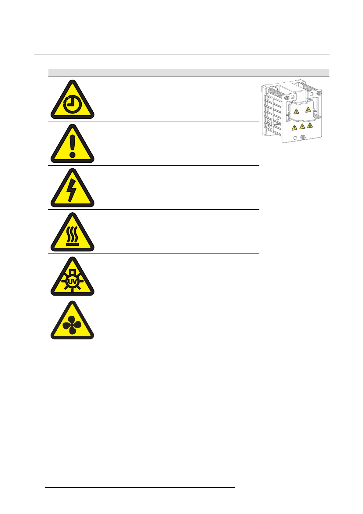
2.3 Product safety labels
Product safety labels
Label image Label description Label location
The Lamp House is very hot after operation. To avoid
burns, let the projector cool down for at least 15 minutes
before proceeding to remove the Lamp House.
General Warning Hazard
Electric Voltage Hazard
Hot Surface Hazard
UV Hazard
Hazardous moving parts.
Keep away from moving fan blades.
Keep fingers and other body par ts away.
On the fans inside the projector
10 R5906693 DP2K-E SERIES 19/06/2015
Page 15
2.4 Light beam Hazard Distance (HD)
HD
Light beam Hazard Distance (HD) is the distance from the source at which the intensity or the energy per sur face unit
becomes lower than the applicable safety limit. The light beam can thus be considered as dangerous if the operator
is closer from the source than the HD.
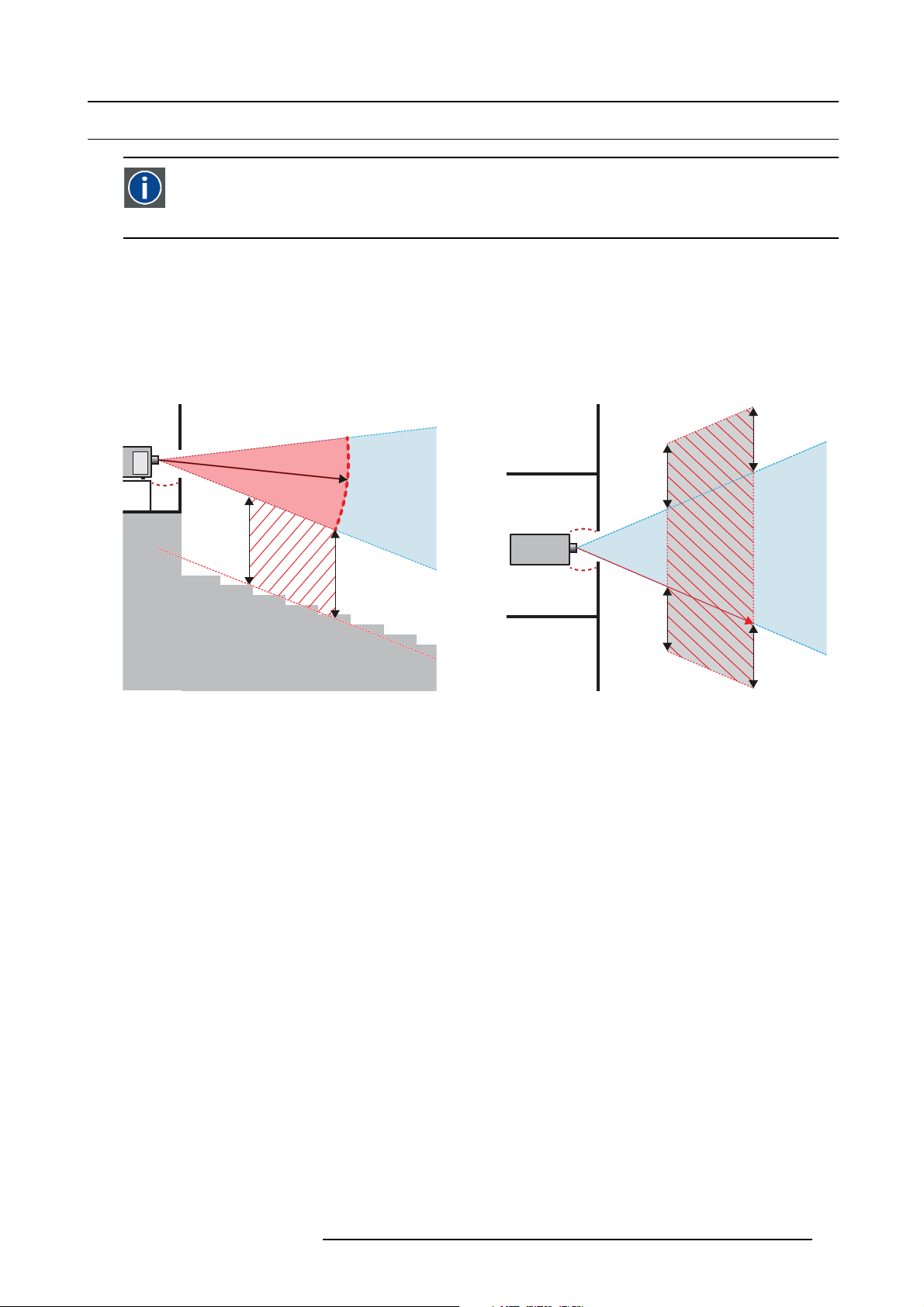
Restriction Zone (RZ) based on the HD
The HD is defined from the projection lens surface towards the position of the lowest projected beam where the irradiance equals
the applicable safety limit. T he HD depends on the amount of lumens produced by the projector and the type of lens installed. See
next chapter HD in function of the lens Throw Ratio (TR).
To protect untrained users the installation shall comply with the following installation requirements: light output levels in excess of the
limits shall not be permitted at any point less than 2.0 meters (SH image 2-1) above any surface upon which persons are assumed
to stand or 1 meter (SW image 2-1) below or in lateral separation from any place where such persons are as sum ed to be. See
image 2-1.
2. Safety
RA TH
HD
RA
SH
RZ
SH
Image 2-1
ASideview.
B Top view.
RA Restricted Access location (booth area of projector).
PR P rojector.
TH Theater.
RZ Restriction Zone in the theater.
SH S eparation Height. Must be minimum 2 meter.
SW Separation W idth. Must be minimum 1 meter.
Based on national requirements, no person is allowed to enter the projected beam within the zone between the projection lens and
the related hazard distance (HD). This s hall be physically impossible by creating sufficient separation height or by placing bar riers.
The minimum separation height takes into account the surface upon which persons are assumed to stand.
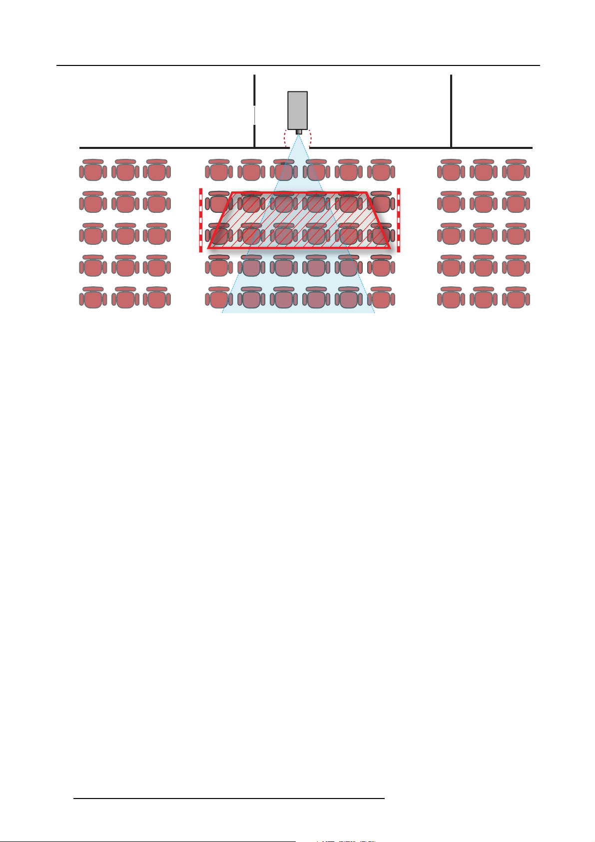
On image 2-1 a typical setup is displayed. It must be ve rified by the installer if these m inimum requirements are m et. If r equired a
restricted zone (RZ) in the theater must be established. This can be done by using physical barrier, like a red rope as illustrated in
image 2-2.
PR
(B) TOP VIEW(A) SIDE VIEW
TH
HD
SW
SW
SW
RZ
1m
SW
R5906693 DP2K-E SERIES 19/06/2015
11
Page 16
2. Safety
Image 2-2
PR
12 R5906693 DP2K-E SERIES 19/06/2015
Page 17
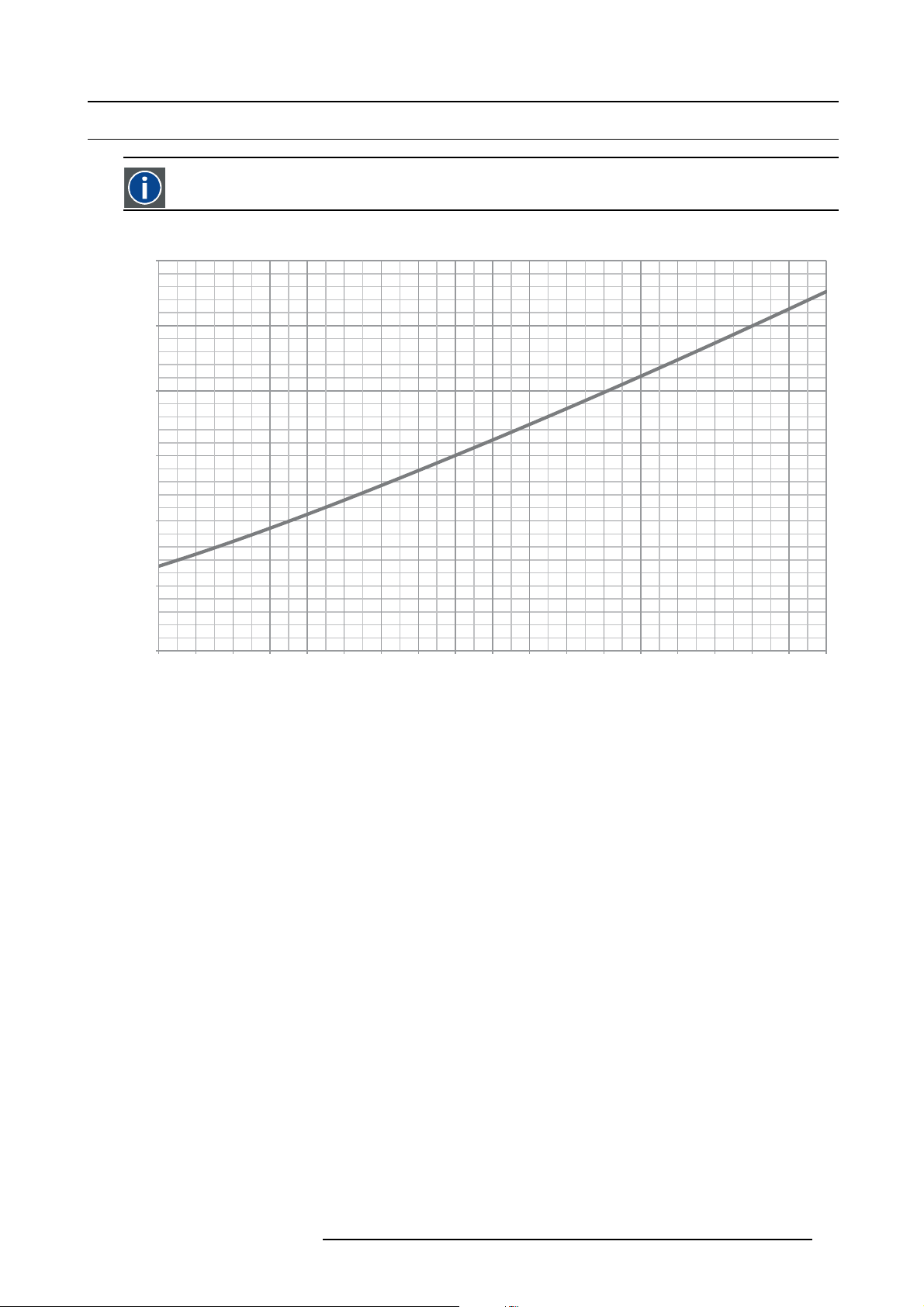
2.5 HD in function of the lens Throw Ratio (TR)
TR (Throw Ratio)
The ratio of the distance to the screen (throw) to the screen width.
Hazard Distance
1,2
1
0,8
0,6
HD [m]
0,4
2. Safety
0,2
0
1,0 1,2 1,4 1,6 1,8 2,0 2,2 2,4 2,6 2,8 3,0 3,2 3,4 3,6 3,8 4,0 4,2 4,4 4,6
Image 2-3
HD (in meter) in function of the Throw Ratio (TR)
TR
R5906693 DP2K-E SERIES 19/06/2015 13
Page 18

2. Safety
14 R5906693 DP2K-E SERIES 19/06/2015
Page 19

3. Getting started
3. GETTING STARTED
About this chapter
Read this ch apter before installing your DP2K-E series projector. It contains important information conc erning installation requirements for the DP2K-E series projector, such as minimum and maximum allowed am bient temperature, humidity conditions, required
safety area around the installed projector, required power net, etc.
Furthermore, careful consideration of things such as image size, ambient light level, projector placement and type of screen to use
are critical to the optimum use of the projection system.
Barco provides a guarantee relating to perfect manufacturing as part of the legally stipulated terms of guarantee. Observing the specification mentioned in this chapter is critical for projector performance. Neglecting
this can result in loss of warranty.
Overview
• Installation requirements
• Unpacking the projector
• Initial inspection
R5906693 DP2K-E SERIES 19/06/2015
15
Page 20

3. Getting started
3.1 Installation requirements
Environment conditions
Table below summarizes the physical environment in wh ich the DP2K-E series projector may be safely operated or stored.
Environment Operating Non-Operating
Ambient Temperature 10°C (50°F) to 35°C (95°F) -20°C (-4°F) to 60°C (140°F)
Air cleanliness Clean office environment (equivalent with cleanroom
Humidity
Altitude
Let t he projector acclimatize after unpacking. Neglecting this may result in a startup failure of the Light Processor Unit.
standard ISO 14644-1 ISO Class 9)
0% to 85% RH Non-condensed 0% to 93% RH Non-Condensed
-60 (-197Ft) to 2000m (9843Ft) -60 (-197Ft) to 10000m (32810Ft)
Cooling requirements
The projector is fan cooled and must be installed with sufficient space around the projector head, minimum 20 cm (8 inch) to ensure
sufficient air flow. It s hould be used in an area where the ambient temperature, as measured at the projector air inlet, does not
exceed 35°C (95°F).
Main Power requirements
The DP2K-E series projector operates from a nominal mono phase power net with a separate earth ground PE.
n.a.
Projector Power requirements
DP2K-6E
The powe r cord required to connect the projector with the power net is not delivered with the projector. It is the responsibility of the
customer to provide the correct type of power cord. The cross-sectional area of the conductors in the power supply cord shall not
be less than 1mm
To protect operating personnel, the National Electrical Manufacturers Association (NEMA) recommends that the instrument panel
and cabinet be grounded. In no event shall this projector be operated without an adequate ca binet ground c onnection.
The AC supply must be installed by a qua lified electrician in conformance to local codes. Hardware, wire sizes and conduit types
must comply with local codes.
A re adily accessible disconnect device shall be inco
2
(18AWG), minimu m 300V.
200-240 VAC, 50-60Hz, 6,25A at 200 VAC
rporated externally to the equipment for removal of the power.
UPS requirements
The Uninterruptible Power Supply (UPS), also known as a Continuous Power Supply (CPS), must have an output voltage of 20 0240V at 50-60Hz and must be capable of delivering an output power of 250W. This UPS provides only power for the electronics and
lamp cooling, but not for the lamp .
The connection between the UPS unit and the UPS inlet of the projector must be done with a certified AC power supply cord of
minimum 0,75 mm² or 18 AWG and minimum 300V.
WARNING: Disconnect the power cord for removal o f all power f rom the unit.
The DP2K-E series projector does not have a built in UPS unit.
Projector weight
Do not unde restimate the weight of the DP2K-E series projector. The projector weights approximately 53 kg (116.8 lb.) without lens.
Ensure that the pedes tal on which the projector is installed is capable of supporting the complete load of the system. Minimum 4
adult persons are needed to carry the projector.
16
R5906693 DP2K-E SERIES 19/06/2015
Page 21

3. Getting started
Barco offers a pedestal for the DP2K-E series projector. This universal pedestal allows for a solid and easy
setup of the projector. The universal pedestal support 19” rack systems. (pro jector peripherals such as alternative content switchers, ShowVault, etc.)
R5906693 DP2K-E SERIES 19/06/2015 17
Page 22
3. Getting started
3.2 Unpacking the projector
What you need to do?
Upon delivery, your projector is packed into a carton box upon a wooden/plastic pallet and sec ured with banding and fastening clips.
Furthermore, to provide protection during transportation, the projector is surrounded by foam. Once the projector has arrived at
the installation site, it needs to be removed from its carton box and wooden/plastic pallet in a safe manner without damaging the
projector.
How to unpack your projector?
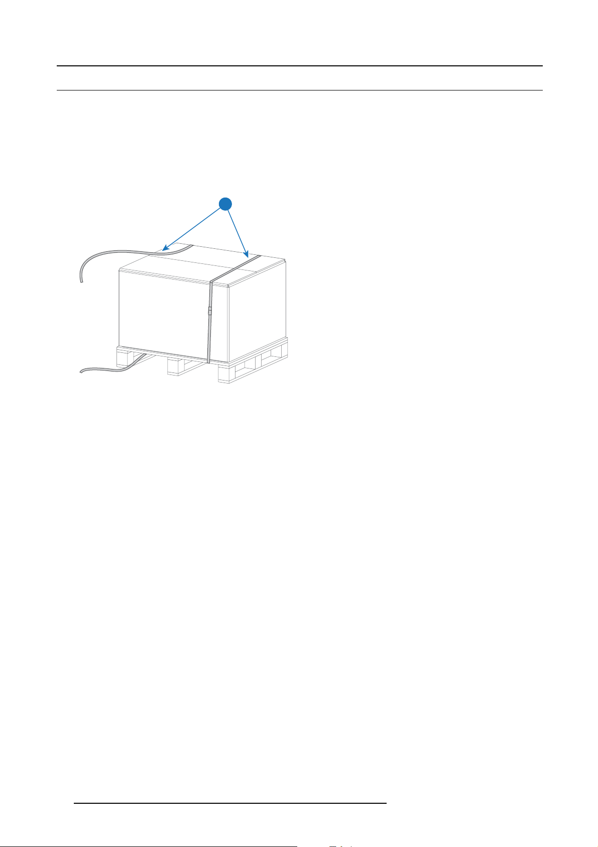
1. L oosen the banding (1) by pulling the free end of the banding loop in the clip.
1
Image 3-1
2. L ift up the carton box (2) as a whole and remove it away from the projector package.
3. Take out the small box (3) between the polystyrene foam on top of the projec tor. This box contains the product documentation
(manuals etc.).
4. Remove the polystyrene foam (4) from the top of the projector.
18
R5906693 DP2K-E SERIES 19/06/2015
Page 23

3. Getting started
2
3
4
Image 3-2
5. O pen the plastic bag and lift the projector out of its packaging, using the handles provided in the projector base.
Image 3-3
6. R emov e the plastic cover from the Lens Holder opening.
After unpacking, allow the projector to acclimatize to a room temperature ranging from 10°C (50°F) to
35°C (95°F) MAX. Neglecting this may result in a start up failure of the Light Processor Unit.
R5906693 DP2K-E SERIES 19/06/2015 19
Page 24

3. Getting started
3.3 Initial inspection
General
Before shipment, the projector was inspected and found to be free of mec hanical and electrical defects. As soon as the projector is
unpacked, inspect for any damage that may have occurred in transit. Save all packing material until the inspection is com pleted. If
damage is found, file claim with ca rrier immediately. The Barco Sales and Service office should be notified as soon as possible.
The p ackaging of the DP2K-E series projector is provided with a shock-watch label. If this shock-watch label
was triggered (red colored at arrival) during transport m ay indicate rough handling by the transpo
In this case, the instructions mentioned on the label, sh ould be followed, which are: adding a note on the “bill
of lading” a nd informing the transport company and the Barco sales and service office as soon as p ossible.
rt company.
Box c ontent
•Projector.
• User and installation m anual (this document).
• Safety manual.
The projector lens is not included in the package of the projector.
Mechanical check
This check should confirm that there are no broken knobs or connectors, that the cabinet and panel surfaces are free of dents and
scratches, and that the operating panel is not scratched or cracked. The Barco Sales and Serv ice office should be notified as soon
as possible if this is not the case.
Tamper l a be l s
During installation please inspect the tamper labels, if they are damaged please contact Barco tech support.
The tamper labels are required by DCI to provide easy visual indication if the equipment was tampered with. T he projectors are
tested and labeled for shipping to ensure that the system was not compromised before reaching the customers final destination.
These tamper labels can be found on the top cover plate from the Light Processor com partment, the side cover plate from the Light
Processor compartment, on the internal c over of the card cage and o
See chapter "Removal and installation of the projector covers", page 119, for instructions on how to remove the projector covers.
n the ICMP.
Image 3-4
Barco tamper label (required for DCI).
20 R5906693 DP2K-E SERIES 19/06/2015
Page 25

4. Installation process
4. INSTALLATION PROCESS
About this chapter
After you have unpacked and checked the projector, you can start with the installation process of your DP2K-E series projector. This
chapter gives an overview of all the different stages in the installation process which you have to be followed to set your DP2K-E series projector up and running. Each stage is briefly described and refers to more detailed step by step procedures in this manual.
Use this overview as a checklist to ensure that all stages have been followed in the setup process of the DP2K-E series
projector.
Let the projector acclimatize to ambient conditions after unpacking. Neglecting this may result in a startup
failure of the light processor unit.
Overview
• Installation process overview
R5906693 DP2K-E SERIES 19/06/2015
21
Page 26

4. Installation process
4.1 Installation process overview
Installation process from A to Z
1. C heck if all installation requirements are fulfilled such as the environment conditions of the installation area, electrical facili-
ties, etc. Note that a solid pedestal is required to support the projector. For more info see topic installation requirements.
2. P h ysical installation of the p rojec tor upon its pedestal. See chapter "Positioning the DP2K-E series projector at port w indow ",
page 24.
3. E lectrical connection with the power net. See chapter "Connecting the projector with the power net", pa
4. In stallation of a UPS to the projector electronics (if applicable). See chapter "Con necting a UPS to the projector electronics",
page 28.
5. In stallation o f the lens. First select a lens with appropriate throw r atio covering the screen size and the projector - screen
distance. Then install the lens in the lens holder of the projector. For more information about available lenses, lens selection and
lens installation see chapter "Lenses & Lens selection", page 31.
Caution: The projector is delivered with a plastic cover inside the Lens Holder. Remove the cover prior to installing the lens.
6. In stallation of the ICM P (only in case no ICMP is factory installed).
7. Installation of the Communicator Touch Panel. See chapter "Installing the Touch Panel interface", pa
8. S w itch on the projector. The projector can now be switched on. Place the ON/OFF switch of the projector in the ”I” position.
As a result the projector starts to initialize. The status lights of the projector lights up GREEN once the projector is initialized. In
case the status lights up RED m ay indicate a tamper event during transport. If so, contact Barco customer service.
9. S elect the corresponding lens parameters for the installed lens. See us er guide of the Communicator chapter Installation >
Advanced > Lens parameters.
10.Alignment of the projected image on the screen. The image can be aligned with the sc reen size of the application. Follow
the next steps to achieve that:
a) Press the STANDBY button on the Local Keypad to activate the lamp.
b) Press the DOWSER button on the Local Keypad to open the electronic dowser of the projector. The electronic dowser is open
if the color of the DOWSER button is GREEN.
c) Press the TEST PATTERN button on the Local Keypad to project one of the internal test patterns of the projector on the
screen.
d) Performa“Lens Homing”. See user guide of the Communicator.
e) Use the lens ZOOM, SHIF T and FOCUS buttons on the Local Keypad to match the projected image with the screen. Tilt the
projector in case you can not SHIFT the image completely upon the screen. See
port window", page 24.
See chapter "Local Keypad", page 41, for detailed description of the Local Keypad buttons.
11. Adjusting the light path. Normally the lens holder and the convergence of the projector are perfectly adjusted at the factory.
Nevertheless, some applications require a readjustment of the lens holder, c onvergence or both. See procedure "Scheimpflug
adjustment", page 82, and "Convergence", page 91.
12.Creating screen files, lens files, light sensor calibration (LSC) files, and m acro files for FLAT and for SCOPE. See user
guide of the Communicator.
13.Backup of all projector configuration files. See user g uide of the Communicator.
14.Registration of the projector. The DP2K-E series projector is DCI compliant and should be registered.
15.Projection of a digital cinema movie.
Download the ICMP device certificate, request KDM and DCP from your content supplier, ingest KDM and DCP, and play out the
movie. for detailed instructions see chapter "ICMP", page 47, and user guide of the Communicator and/or (Web) Commander.
Use the Com m unicator (Touch Panel) to configure the applied source. See the user guide of the Communicator (Touch Panel)
for more detailed information.
"Positioning the DP2K-E series projector at
ge 27 .
ge 72.
22
R5906693 DP2K-E SERIES 19/06/2015
Page 27

5. PHYSICAL INSTALLATION
About this chapter
This chapter describes how the mechanical and electrical set up of your DP2K-E series pr ojector has to be done.
Overview
• Positioning the DP2K-E series projector at port window
• Connecting the projector with the power net
• Connecting a UPS to the projector electronics
5. Physical installation
R5906693 DP2K-E SERIES 19/06/2015
23
Page 28
5. Physical installation
5.1 Positioning the DP2K-E series projector at port w indow
WARNING: The installation of the DP2K-E series projector requires at least 4 adult persons.
General guidelines
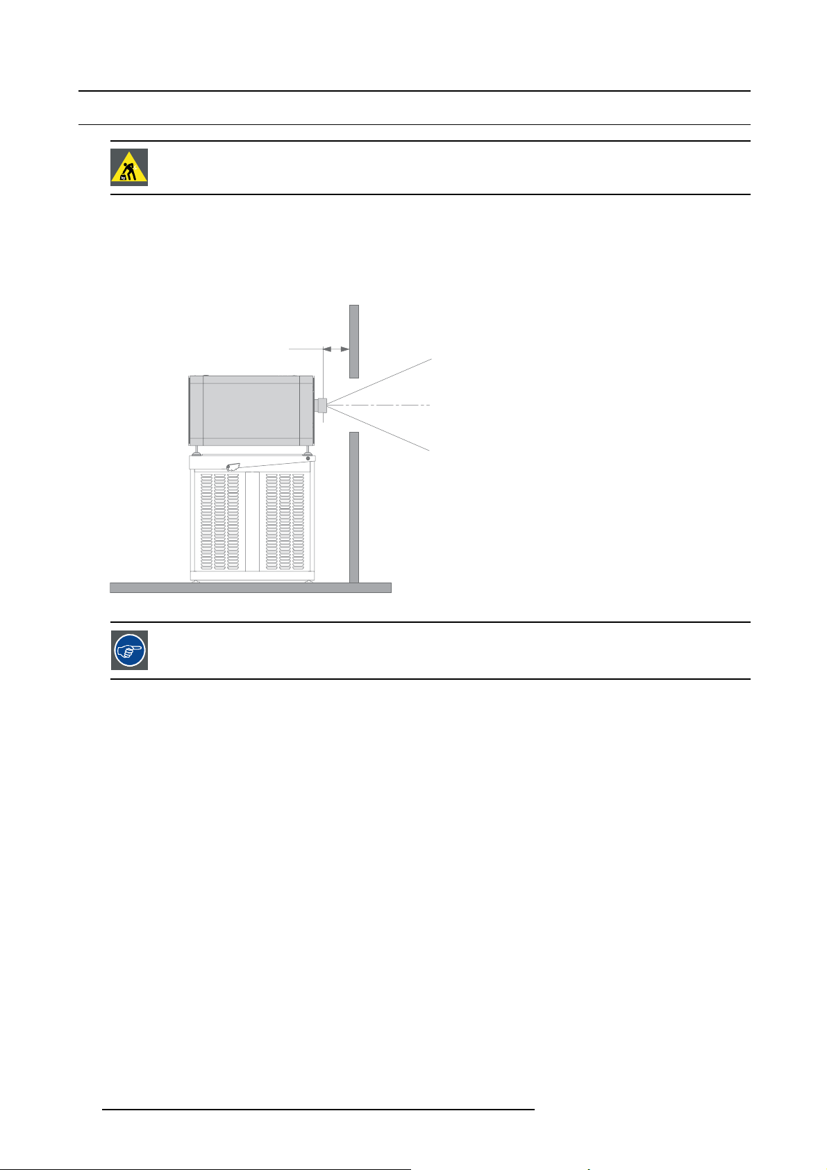
• Use a solid pedestal to mount the DP2K-E series projector on to. Ensure that the pedestal can s upport t
projector and that all feet of the projector are captured.
• The pedestal should be placed in front of the port window wall in a manner such that the projector lens is at a minimum distance
of 20 centimeters from the port window.
20 cm
Image 5-1
Barco offers a pedestal for the DP2K-E series projector. This universal pedestal allows for a solid and easy
setup of the projector. The universal pedestal support 19” rack systems. (pro jector peripherals such as alternative content switchers, ShowVault, etc.)
he weight of the
Necessary tools
• 14mm open end wrench
• 17mm open end wrench
Projector centering
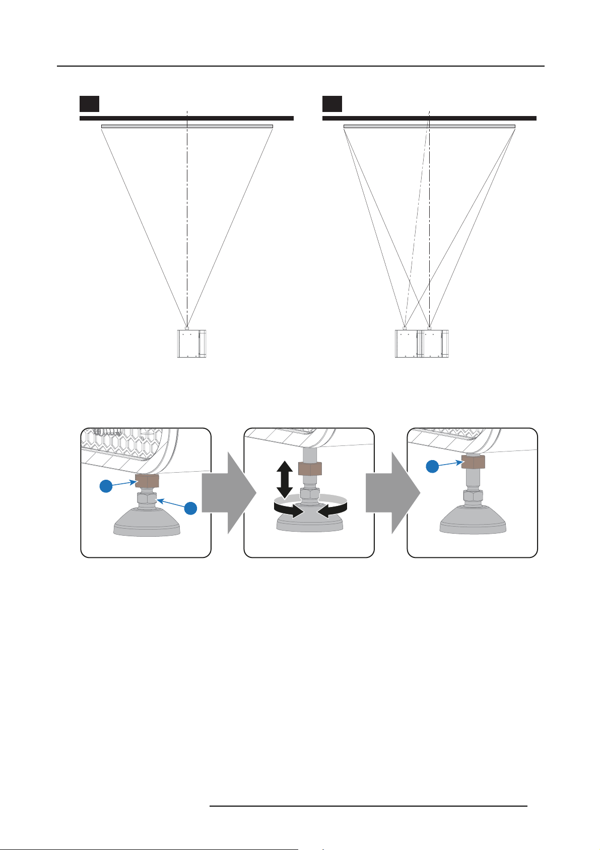
1. If the projector is standalone in front of the port window, center the projector with the theatre screen (A).
2. If an analog film projector is already present (projector will be off-center), try to optimize aim (B).
Note: Unlike analog film projectors, it is best to keep the projector lens surface as parallel as possible to the screen, even if it
is significantly above the screen center.
Caution: The front foot has an adjustment range of maximum 70mm. The back feet maximum 125mm.
24
R5906693 DP2K-E SERIES 19/06/2015
Page 29
5. Physical installation
The off-center position slightly increases side keystone, but will m inimize horizontal lens offset required.
A B
Image 5-2
3. P roceed to level the projector by adjusting the feet of the projector as follows:
- Loosen the nut (1) on the threaded rod of the three projector feet. Use a 17mm open wrenc h.
- Adjust the height of the 3 legs to level the projector. U se a 14 mm wrench to adjust the height as illustrated (2).
- Secure the leg height by tightening the nuts (1) of each projector foot.
SCREEN CENTER SCREEN CENTER
OFF-CENTER
1
1
2
Image 5-3
4. L ater, when the projector is up-and-running, adjust precise im age geometry and placement.
Projector tilting
In an ideal installation, the DP2K-E series projector lens surface is centered with and parallel to the screen. This orientation helps
to ensure optimized lens performance with minimal offset. If this position is not possible (such as when the projector is signifi cantly
higher than the center of the screen), it is better to rely on offset rather than extra tilt. I n other words, use the SHIFT functionality
of the Lens Holder prior to tilt the projector.
1. B efore adjusting tilt, make s
2. C heck the degree of screen tilt, or measure this incline with a protractor at the screen.
3. Tilt the projector to closely match this screen tilt angle as follows:
- Loosen the nut (1) on the threaded rod of the three projector feet. Use a 17mm open wrenc h.
- Adjust the height of the 3 legs unt
open wrench to adjust the height as illustrated (2).
- Secure the leg height by tightening the nuts (1) of each projector foot.
ure the projector is as well-centered with the theatre screen as possible for the installation area.
il the projected image matches the projection port window and the screen tilt. Use a 14mm
R5906693 DP2K-E SERIES 19/06/2015
25
Page 30

5. Physical installation
Image 5-4
CAUTION: The DP2K -E series projector may tilt maximum 15° forward and maximum 5° backwards. No tilt is
allowed sideways.
90°
Inclined screen
The b ack feet of the projector can be turned out maximum 125mm.
if the front foot is completely turned in.
Barco offers a p edestal for the DP2K-E series projector. This universal pedestal allows you to easily tilt the
projectorforwardupto6°.
Use the tilt of the projector feet and the pedestal to get sufficient tilt.
This correspond w ith a forward tilt of 12°
26 R5906693 DP2K-E SERIES 19/06/2015
Page 31

5.2 Connecting th e projector with the power net
WARNING: The total electrical installation should be protected by an appropriate rated and readily accessi-
ble disconnect switch, circuit breakers and ground fault current interrupters. The installation shall be done
according to the local electrical installation co des.
5. Physical installation
CAUTION: The cross-sectional area o f the conductors in the Power Supply Cord shall be not less than 1mm
(18AWG).
Necessary tools
No tools.
Necessary parts
Power supply cord 1mm2(18AWG), m in. 300V with IEC 60320 - C13 connector
How to connect the main AC power with the DP2K-E series projector projector?
1. R emov e the right side cover of the projector. See procedure "Removal of the right side cover", page 125.
2. M ake sure that the projector is switched off. Position the power switch in the ’0’ (OFF) position (1).
3. C onnect the female side of the power cord with the power input socket of the projector (2).
2
1
2
Image 5-5
4. C onnect the male side of the power cord to the local power net.
5. Install the right side cover of the projector. See
procedure "Installation of the right side cover", page 130.
R5906693 DP2K-E SERIES 19/06/2015
27
Page 32

5. Physical installation
5.3 Connecting a UPS to the projector electronics
WARNING: Only use UPS units w hic h are suitable for the DP2K-E series projector. See chapter “Installation
requirements” for more information about the requirements of the UPS.
Necessary tools
3mm Allen wrench
How to connect the UPS
1. R emov e the right side cover of the projector. See procedure "Removal of the right side cover", page 125.
2. R emov e the rear cover. See "Removal of the rear cover", page 121.
3. R emov e the 2 s crews (1) of the SMPS cover (2) and remove the cover. Use a 3mm Allen wrench.
2
1
1
Image 5-6
4. P lug out the connector which is plugged into the AC socket ( 3). Plug the connector in the UPS socket (4).
3
Image 5-7
5. Install the SMPS cover and install the 2 sc rews. Use a 3mm A llen wrench.
6. Install the rear cover. See "Installation of the rear cover", page 134.
7. Install the UPS according to the instructions of the man ufacturer and the local regulations.
8. C onnect the power output cord from the UPS unit to the UPS inlet socket (5) of the projector.
28
4
R5906693 DP2K-E SERIES 19/06/2015
Page 33

5. Physical installation
5
Image 5-8
9. Install the right side cover of the projector. See procedure "Installation of the right side cover", page 130.
CAUTION: The electrical connection with the UPS INLET socket of the projector must be do ne with a certified
AC power supply cord (minimum 0,75 mm² or 18 AWG and minimum 300V)
R5906693 DP2K-E SERIES 19/06/2015 29
Page 34

5. Physical installation
30 R5906693 DP2K-E SERIES 19/06/2015
Page 35

6. Lenses & Lens selection
6. LENSES & LENS SELECTION
About this chapter
This chapter gives an overview of available lenses for your DP2K-E series projector and explains how to select the best suited lens
for a specific situation using the lens calculator. Also, it is explained how to install and remove a lens from the projector Lens Holder
and how to shift, zoom a nd focus the lens.
CAUTION: Never transport the projector with a Lens mounted in the Lens Holder. Always remove the Le
before transporting the projector. Neglecting this can damage the Lens Holder and Prism .
CAUTION: Caution when removing or installing the lens! Fragile parts at the inner side of the Lens Holder.
Each time a lens is manipulated (e.g. removed and installed in a p rojector), it needs to be homed and returned.
Overview
• Available lenses
• Lens selection
• Lens installation
• Lens removal
• Lens shift, zoom & focus
ns
R5906693 DP2K-E SERIES 19/06/2015
31
Page 36

6. Lenses & Lens selection
6.1 Available lenses
Which lenses are available?
For the DP2K -E series projector the 0.69” DC2K lens family is used.
The table below is subject to changes and w as last up dated on 15 O ctober 2012. Consult https://my.barco.com
for the most recent information about available lenses for the DP2K-E series projector.
0.69” DC2K zoo m lenses
Product Number 2K zoom range Image Motor Block type
R9856520 1.2 - 1.7 image 6-1 M
R98565201 1.2 - 1.7 B
R9856521 1.34 - 1.9 image 6-2 M
R9856522 1.5 - 2.15 image 6-3 M
R9856523 1.7 - 2.55 image 6-4 M
R9856524 2 - 3.9 image 6-5 M
R98565241 2.09 - 3.9 F
Image 6-1
0.69" DC2K zoom lens 1.2 - 1.7 (R9856520)
Image 6-4
0.69" DC2K zoom lens 1.7 - 2.55 (R9856523)
Image 6-2
0.69" DC2K zoom lens 1.34 - 1.9 (R9856521)
Image 6-5
0.69" DC2K zoom lens 2 - 3.9 (R9856524)
Image 6-3
0.69" DC2K zoom lens 1.5 - 2.15 (R9856522)
32 R5906693 DP2K-E SERIES 19/06/2015
Page 37

6. Lenses & Lens selection
6.2 Lens selection
WhichlensdoIneed?
1. G o to Barco’s website on www.barco.com and click on myBarco
2. L ogin on .
If you are not yet registered create a login and password. With the created login and password, it is possible to enter myBarco .
When your login is correct, the start page is displayed.
3. Click the Support tab, then Digital cinema calculator (on the left of the screen) and select the appropriate lens calculator.
The lens calculator (see screenshot, image 6-6) will be displayed.
The lens calculator allows you to have an overview of which lenses are suitable for your specific project o r setup. Just make you r
selection of pa rameters and all possible confi gurations are displayed.
Image 6-6
Digital cinema lens calculator
Take into account that when t he projector is tilted the Screen Width you have to fi ll in should be larger than
the physical screen w idth due to the keystone distortion of the projected image. How much larger depends
ontheamountoftilt.
Due to production tolerances the real distances can differ by 2% from the calculated values.
For critical situations (fixed installs that use the lens at one of its extreme zoom positions) this should be
taken into account.
R5906693 DP2K-E SERIES 19/06/2015 33
Page 38

6. Lenses & Lens selection
6.3 Lens installation
How to install a lens into the Lens Holder?
1. Remove the foam rubber in the o pening of the Lens Holder if not removed yet.
2. Take the lens assembly out of its packing material and remove the lens caps on both sides.
Caution: Do not touch the glass of the lens!
3. E nsure that the Lens Holder stands in the On-Axis position (horizontal and vertical mid position).
4. P lace the Lens Holder in the “locked” position by moving the lens lock handle (1) downwards, away from the lens power supply
socket (2).
5. G ently insert the lens in such a way that the lens co nnector matches the socket. To prevent collision of the lens with the critical
electronics inside the projector, ensure you centre the lens and keep it on-axis while approaching.
Caution: Do not acc identally bump with the lens against the electronic boards inside the Lens Holder.
Warning: Do not release the Lens yet, as the Lens m ay fall out of the Lens Holder.
6. Push the lens completely against the Lens Holder front plate. An audible click should be noticed. Onc e seated, there may be
no airgap between lens flange and Lens Holder front plate.
Caution: Ensure that the loc k handle remains in the “locked” position.
2
1
Image 6-7
Note: For frequent installation and removal of the lens it is recommended to install the lens while the lock handle is in “open”
position (upwards) and put the lock handle in “locke
installed by trying to pull the lens out of the Lens Holder. (this alternative procedure result in less w ear of the Lens Holder)
7. Check if the lens is really secured by trying to pull the lens out of the Lens Holder.
8. A ctivate the corresponding lens parameters for the installed lens. (See user guide of the Communic ator chapter Installation >
Advanced > Lens parameters)
Caution: Not using the correct lens parameters could result in lens damage.
d” position once the lens is inserted. Then check if the lens is properly
C
k
c
i
l
Image 6-8
9. P erform a lens HOME & RETURN operation. (See user guide of the Communicator chapter Installation > Advanced > Lens
parameters)
Note: The HOME & RE TU RN operation enables the projector to determine the reference positions of the motorized ZOOM and
FOCUS barrels of the installed lens.
CAUTION: Never transport the projector with a Lens mounted in the Lens Holder. Always remo ve the Lens
before transporting the projector. Neglecting this can damage the Lens Holder and Prism .
34 R5906693 DP2K-E SERIES 19/06/2015
Page 39

6. Lenses & Lens selection
6.4 Lens removal
How to remove a lens from the Lens Holder?
1. S upport the lens with one hand while you unlock the lens holder by sliding the lock handle (1) towards the “unlocked” position as
illustrated.
2. G ently pull the lens out of the lens holder, maintaining its coaxial direction.
Caution: Do not acc identally bump with the lens against the electronic boards inside the Lens Holder.
1
Image 6-9
It’s recommended to place the Lens caps of the original Lens packaging, back on both sides o f the removed
Lens to protect the optics of the Lens.
It’s recommen ded to place the plastic cover of the original projector packaging, back into the Lens opening
to prevent intrusion of dust.
R5906693 DP2K-E SERIES 19/06/2015 35
Page 40

6. Lenses & Lens selection
SHIFT
ZOOM
6.5 Lens shift, zoom & focus
Motorized lens adjustment
The DP2K-E series projector is equipped with a moto rized lens shift and zoom & focus functionality.
Maximum shift range
The lens can be shifted with respect to the internal optics of the projector (DMD) which results in a shifted image on the screen
(Off-Axis). A 100% shift means that the centre point of the projected image is shifted by half the screen size. In other words, the
centre point of the projected image falls together with the outline of the image in an On-Axis projection. Due to mechanical and
optical limitations the shift range is limited as well.
All lenses have a shift range of 50% up, 50% down, 30% left, and 30% right. This range is valid for all throw ratios. Within these shift
ranges the projector and lens perform excellently. Configuring the projector outside these shift ranges will result in a slight decline
of image quality.
+50%
-50%
-30%
+30%
L R
Image 6-10
PDMD.
F Field of view.
U
+50%
F
P
U
D
SIDE VIEW
-30% +30%
-50%
D
F
P
P
L
TOP VIEW
R
F
It’s mechanical possible to shift outside the recommended fi eld of view (±90% UP/DOWN and ±50%
LEFT/RIGHT), but this will result in a decline of image quality depending on the used lens and the zoom
position of the used lens. Furthermore, shifting too much in both directions will result in a blurred image
corner.
How to shift the lens of the DP2K-E series projector ?
1. U se the up and down arrow buttons on the Loc al Keypad to shift the lens vertically and use the left and right arrow buttons
on the Local Keypad to shift the lens horizontally.
SHIFT
Image 6-11
How to zoom in or out?
1. Use the “+” and “-” zoom buttons on the Local Keypad to zoom in or out.
ZOOM
Image 6-12
How to focus?
1. U se the “+” and “-” focus
FOCUS
Image 6-13
36 R5906693 DP2K-E SERIES 19/06/2015
buttons on the Local Keypad to focus the image on the screen.
Page 41

6. Lenses & Lens selection
Take into account that the lens focus may slightly drift while the lens is warming up from cold to operation
temperature. This is a typical phenomenon for projection lenses used with high brightness projectors. The
operation tempe rature of the lens is reached after approximately 30 minutes projection of average video.
Button backlight colors
• BLUE : The default backlight color of the Shift, Zoom and Focus buttons is blue which indicates that the button is enab led.
• PURPLE : W hen pushing the Shift, Zoom or Focus button the backlight color is purple of t he part of the button that is pushed.
This indicates that the requested action is ongoing.
• RED : The backlight color of the Shift, Zoom and Focus buttons is red in case of end of range.
R5906693 DP2K-E SERIES 19/06/2015
37
Page 42

6. Lenses & Lens selection
38 R5906693 DP2K-E SERIES 19/06/2015
Page 43

7. Input & Communication
7. INPUT & COMMUNICATION
About this chapter
This chapter des cribes the functionality of the Local Keypad, the projector Status Light (tail light) and the different input and communication ports of your DP2K-E series projector.
Note that all information about the ICMP is gathered into one separated chapter: "ICMP", page 47.
Overview
• Introduction
• Local Keypad
• Projector Status
• Cinema Controller
R5906693 DP2K-E SERIES 19/06/2015
39
Page 44

7. Input & Communication
7.1 Introduction
General
The Input & Communication side of the DP 2K-E series projector consists of a Local Keypad integrated into the projector housing
and a card cage with three slots. The top side of the projector is equipped with a tail light which reflects the status of the projector.
The projector card cage is equipped with an ICMP. See illustration below. Note that all information about the ICMP is gathered into
one separated chapter: "ICMP", page 47.
1
3
2
Image 7-1
1 Projector status light.
2 Power ON/OFF switch.
3 Local keypad.
4 Barco Cinema Controller.
5ICMP.
CAUTION: A unit may only be removed from the card cage by qualified service personnel. Removing one of
the board s (except for the Cinema Controller) will result in an authorization request upon starting.
5
4
40 R5906693 DP2K-E SERIES 19/06/2015
Page 45

7.2 Local Keypad
ZOOM
SHIFT
Identification of the buttons
7. Input & Communication
21 3 4 5 6 7
8 9 10 11 12
1 4
2 5
DOWSER
FOCUS
SHIFT
ZOOM
3 6
Image 7-2
Functionality of the buttons
Numeric buttons (No.1 - 6)
1
All the Numeric buttons (reference 1 image 7-2) of the Local Keypad have a white backlight during normal operation.
When the au thorization process is activated with the (security) K ey button, the backlight color of the Numeric buttons
changes to yellow. Each button can be linked to a macro whic h allows you to setup the projector to your requirements
with one push of a button.
Marker area
2
Each Numeric button has a marker area (reference 2 image 7-2) where you can write down the name of the Macro.
Standby button
3
Standby b utton (reference 3 image 7-2) switches the lamp and lamp electronics immediately ON or OFF. The lamp cooling
fans remain active for about 5 minutes. The backlight color of the Standby button remains white in standby mode and
changes to green in operation mode.
Dowser button
4
The Do wser button (reference 4 image 7-2) opens or closes the electronic dowser. The backlight color of the Dowser button
is green when the dowser is open and white when the dowser is closed.
Test Pattern button
5
The Test Pattern button (reference 5 image 7-2) gives direct access to a limited set of the internal test patterns of the
projector. This is a toggle button. To exit the Test Pattern mode toggle through all test p atterns. Note that the convergence
test pattern is not included in this set. T he backlight color of the Test Pattern button is green if one of the test patterns
is activated and white if none is activated.
Focus button
6
The Foc us button (reference 6 image 7-2) allows you to focus the projected image on the screen. The backlight color of th e
Focus button is red in case the end of range is reached.
Shift button
7
The Shift button (reference 7 image 7-2) allows you to shift the lens up/down or left/right. The backlight color of the
Shift button is red in case the end of range is reached.
Sleep button
8
Pushing the Sleep button (reference 8 image 7-2) for 3 seconds puts the projector in Sleep mode (energy saving). In case
the projector is processing the after cooling cycle then the projector goes in Sleep m ode after finishing the after cooling
cycle. The backlight color of the S leep button is purple during a fter cooling and white in Sleep mode.
Push the Sleep button for 3 seconds in Sleep mode to aw ake the projector (put in Standby). The backlight color of the Sleep
button in Standby m ode is green.
Enter or leave Sleep mode can also be done v
Macros (not editable) with GPIO, or via the Communicator.
The Sleep button is disabled if the lamp is on.
R5906693 DP2K-E SERIES 19/06/2015
ia a 2 dedicated projector command (USB/Ethernet), or via two predefined
41
Page 46

7. Input & Communication
Star button
9
Star button (reference 9 image 7-2). User defined button. (Future expansion)
Key button
10
The (security) Key button (reference 10 image 7-2) is used for the authorization procedure to clear tamper errors etc.
(service pur poses). Pin codes can be added/changed with the Communicator.
Zoom button
11
The Zoom button (reference 11 image 7-2) allows you to z oom in or out the projected image on the screen. The backlight
color of the Zoom button is red in case the end of range is reached.
Media control buttons
12
Buttons (reference 12 image 7-2) allowing you to navigate through the content on the integrated media server. If a test
pattern is activated, the projector will not show the content on the integrated media server.
Button backlight colors
• PURPLE : T he backlight color of a button (or part of) is pur ple whe n pushed. This indicates that the requested action is ongoing.
The backlight color remains purple until the requested action is finished.
• GREEN : depending on the button the green backlight color can have a different meaning:
- for the Standby button a green backlight color means that the lamp is switched ON.
- for the Sleep button a green backlight color means that the projector is awake.
- for the Dowser button a green backlight color means that the electronic dowser is open (applied source can be displayed).
- for the Test Pattern button a green backlight color means that one test pattern is activated and thus the applied source can
be displayed.
- for the K ey button a green backlight color means that the projector is s ecured (no tamper event).
• RED : depending on the button the red backlight color can have a different meaning:
- for the S hift, Zoom or Focus button a red backlight color indicates that the end of range is reached.
• YELLOW : The backlight color of the Numeric buttons 1 to 6 of the Local Keypad changes from white t
Key button is pressed.
• WHITE: depending on the button the white bac klight color can have a different me aning:
- for the Standby button a white backlight color indicates that the lamp is OFF (not activated).
- for the Sleep button a white backlight color indicates that the projector is in Sleep mode.
- for the Dowser button a white backlight color indicates that the electronic dowser is closed (applied source can not be displayed).
- for the Test Pattern b utton a white backlight color indicates that no test pattern is selected (applied source can be displayed).
- for the K ey button a white backlight color means that the projector is no t secured (tamper event).
o yellow if the (security)
42
R5906693 DP2K-E SERIES 19/06/2015
Page 47

7. Input & Communication
7.3 Projector Status
About the projector Status Light
The projector Status Light is located at the rear end of the projector (Tail Light). The projector Status Light is real time indicator of
the projector condition.
Image 7-3
Status overview
Depending on the condition of the projector the status light may have 4 colors: Green, Yellow, Red or Blue. Eac h color r epresent a
different state:
Blinking Green Projector is booting up. (Fully booted up when Test Pattern button is white as well)
Green
Yellow Projector is running with warnings. Event can go on but a technical intervention will be necessary in
Red
Blue Projector runs in notification state. Maintenance action required. Lamp run time is exceeded.
Projector is running norm ally.
the near future to prevent a complete stop of the projector.
Projector is in error state. Problem could prevent normal operation. Solve the problem before
continuing with the projector.
New lamp must be installed.
Standby mode
In Standby mode the lamp of the proj
projector is ready to ignite the lamp and project the image. The status light is not different between Standby mode and Lamp ON
mode (fully operational).
ector is switched OFF but all the electronics of the projector remain fully operational. The
Sleep mode
If the projector is in Sleep mode then the status light flashes every ten seconds. The color of the flash depends on the state of the
projector. In other words, the color of the flash will be green in normal state (no warnings, no errors, no notifications).
In Sleep mode the total power consumption of the projector is less than 15W. No fans are turning and the Lamp Power Supply (LPS)
is switched OFF completely. Only the following functionalities of the projector remains active:
• Cinema Controller
• Local Keypad
• Router and external sw itch fully functional
• USB IN port type “ B” (Virtual comport RS232)
• USB OUT port type “A” (To power handheld d evices [500mA MAX]. No other functionality supported)
• GPIO port on the Cinema Controller
Pressing the Sleep button in Standby mode for 3 seconds puts the projector in Sleep mode. In ca se the projector is processing the
after cooling cycle then the projector goes in Sleep mode after finishing the after cooling cycle.
Pressing the Sleep button in Sleep m ode for 3 seconds will awake the projector. The status light will blink for a few seconds (booting
up all inactive boards) and then lights up continuously.
Enter or leave Sleep mode can also be done via 2 dedicated projector command (USB/Ethernet), or via two predefined Macros (not
editable) with GPIO of the C
inema Controller (not the GPIO of the ICMP), or via the Communicator.
R5906693 DP2K-E SERIES 19/06/2015
43
Page 48

7. Input & Communication
The p rojector always boots up in the same mode (E.g. Standby or Sleep) as it was switched OFF.
The Sleep button is disabled if the lamp is ignited.
44 R5906693 DP2K-E SERIES 19/06/2015
Page 49

7.4 Cinema Controller
Location of the communication ports
Image 7-4
Functionality
1
Diagnostic LEDs
The front plate of the Cinema Controller contains 4 diagnostic LEDs to display the status o
image 7-4):
• +VTEC supply (not used on DP2K-E series projector).
• +24V supply.
• +12V supply.
• general power supply (ERROR).
7. Input & Communication
5 6 74321
f the power supply (reference 6
2
USB IN port
The Cinema Controller is equipped with a USB port, type “B” connector, (reference 5 image 7-4) to connect upstream devices
(E.g. PC). This USB port is used to communicate with the projector via RS232 commands (Virtual comport). The USB
IN port remains operational in Sleep mode.
3
USB OUT port
The Cinem a Controller is equipped with a USB port, type “A” connector, (reference 4 image 7-4) which can be used to power
handheld devices within USB spec (MAX 500mA/5V]. No other functionality supported (Future ex pansion). The USB
OUT port remains operational in Sleep mode.
4
3D INTERFACE
3D interface port (reference 3 image 7-4). Can be used to connect ex ternal 3D devices to the projector. All signals necessary
for 3D projection can be provided via this connector. The 3D interface port is disabled if the projector is in Sleep mode.
5
GENERAL PURPOSE INPUT/OUTPUT (GPIO)
This 37 pin connector (reference 2 image 7-4) can be used to send or receive trigger signals from other dev ices. These
input/output pins can b e programmed by macros created with the Com munica tor software. See user’s guide of the
Communicator, section Macro editor, for more information about this functionality. Note that the General Purpose Inputs
accept 24 volt maximum. The GPIO remains operational when the projector is in Sleep mode. So, if the factory predefined
macro to wake up the projector is assigned to one of the free GPI input pins the projector can be awakened via G P IO.
Enter or leave Sleep mode can also be done with GPIO via two predefined Macros (not editable).
6
Wide Area Netw ork (WAN)
Wide Area Network (WAN: 10/100/1000 base-T). Use this Ethernet port (reference 6 image 7-4) to connect the network
which contains the DHCP server.
Once connected to the WAN, users can access the projector from any location, inside or outside (if allowed) their company
network using the Communicator software. This software locates the projector on the network if there is a DHCP server or
the user can insert the correct IP-address to access the projector. Once accessed, it is possible to check and manipulate all
the p rojector settings. Remote diagnostics, control and mon itoring of the projector can then become a daily and very simple
operation. The network connectivity allows detection of potential errors and consequently improves service time.
R5906693 DP2K-E SERIES 19/06/2015
45
Page 50

7. Input & Communication
7
Local Area Network (LAN: 10/100/1000 base-T)
Local Area Network (LAN: 10/100/1000 base-T) with built-in Ethernet switch (port I and port II, reference 7 image 7-4). Use
for projector control and automation. E.g. Touch Panel, content server, ... (not for content streaming!)
As there is a need to daisy chain projectors w hen they are on an Ethernet network, an Ethernet switch is built in. the incoming
network is hereby available for the internal PC and for the next device in the chain. In this way a ’star’ network interconnection
can be avoided. The switch used is a stand alone 10/100/1000Mbit Ethernet switch. This assures no influence on the
network speed. Furthermore, this Ethernet switch remains operational when the projector is in Standby mode.
The connectors used for these Ethernet ports are of the type RJ45, which is compatible with s tandard RJ45 cable connector.
Straight ( most common) as well as cross linked network cables can be used. The 2 ports are functionally identical. Both
ports are connected via the projector switch (Auto sensing enabled).
The connectors u sed for all Ethernet ports are of the type RJ45, which is compatible with standard RJ45 cable
connector. Straight (most common ) as well as cross linked network cab les can be used. Th e 2 ports are
functionally identical. Both ports are connected via the projector switch (Auto sensing enabled).
Cinema Controller functions:
• Ethernet Communication to ICP, Media block or Link decryptor.
• Virtual COM port (RS232) to BARCO Controller on the USB-IN port.
• Standardized 3D interface on board.
• GPIO controls
• Lensholder motors (stepper m otors)
• Stores lens files and lens type / Controls lens
• Lens motor drivers (DC motors)
• Controls lamp power supply
•StoresSNMPkey
• Stores Barco IP address and host name
• Handles reporting of errors, version info & Barco logs to Commu nicator
• Controls ICP board
• Controls Dolby 3D color wheel
• Controls and monitors k eypad (Button module)
• Controls and monitors status lights
•StoresMacrofiles, Input files, Lens files, 3D files and Light Sensor Calibration file (LSC)
Virtual comport (RS232 serial communication)
The USB-IN port of the communication interface supports RS232 serial communication. You can use the RS232 input port to connect
a local PC to your DP2K-E series projector projector. This way you can configure a nd control your DP2K-E series projector p rojector
from your local PC.
Do not forget to set the projector’s baud rate (default = 115200) to match that of the computer.
Advantages of using RS232 serial communication:
• easy adjustment of the projector via PC (or MAC).
• wide range of control possibilities.
• sending data to the pr ojector (update).
• copying data from the projector (backup).
RS232
An Electronic Industries Association (EIA) serial digital interface standard specifying the characteristics of the communication path between two dev ices using either D-SUB 9 pins or D-SUB 25 pins connectors. This standard is used for
relatively short-range communications and does not specify balanced control lines. RS-232 is a serial control standard
with a set number of conductors, data rate, word length and type of connector to be used. The standard specifies com ponent connection standards with regard to computer interface. It is also called RS-232-C, which is the third version
of the RS-232 standard, and is functionally identical to the CCITT V.24 standard. Logical ’0’ is > + 3V, Logical ’1’ is < 3V. The ran ge between -3V and +3V is the transition zone.
46 R5906693 DP2K-E SERIES 19/06/2015
Page 51

8. ICMP
About this chapter
This chapter describes the ICMP in general, the HDDs, the input p orts and the communication ports. Furthermore, the status LEDs
are described and the importance of the device certificate is illustrated.
Image 8-1
8. ICMP
Overview
• ICMP introduction
• ICMP HDD
• ICMP communication ports
• ICMP source input ports
• ICMP reset button and status LEDs
• ICMP HDD status LEDs
• ICMP device certificate
•ICMPconfiguration via Communicator
• Obtaining the Barco ICMP certificate
• Removing a HDD form the ICMP
• Installing a HDD into the ICMP
R5906693 DP2K-E SERIES 19/06/2015
47
Page 52

8. ICMP
8.1 ICMP introduction
About ICMP
The ICMP is a removable electronic assembly situated in the Card Cage of the projector. The ICMP s tores, decrypts and decodes
DCI cinema content and delivers it to the projector in a usable format, all integrated into a single assembly placed directly in the
projector. ICMP is a fully integrated assembly so expected by the operators to facilitate their daily business.
The standard Integrated Cinema Processor functionality from Texas Instruments® is fully integrated into the ICMP. So, the ICMP
replaces the ICP board as well.
21
Image 8-2
1 ICMP with video mezzanine
2 HDDs for ICMP
As an integrated component of the projector, installation and maintenance of the ICM P requires the same skills and the same precautions as an intervention on the projector itself.
For order info see w
ww.barco.com.
Front face of the ICMP
Image 8-3
Front face ICMP with video mezzanine
Card Cage slot location
The Card Cage can be different depending the projector type but it always consists of a button module a nd several removable u nits.
The ICM P (reference 1 ) is inserted into the former ICP slot and IMB slot abov e the Barco Cinema Controller (reference 2).
48
R5906693 DP2K-E SERIES 19/06/2015
Page 53

ICMP location in the Card Cage of a E-series projector.
Image 8-4
8. ICMP
1
2
R5906693 DP2K-E SERIES 19/06/2015 49
Page 54

8. ICMP
8.2 ICMP HDD
About ICMP HDD
The three HDDs (local storage) in the ICMP, are set up in a RAID 5 configuration. This storage technique, that combines multiple
HDD components into a logical unit, manages enough redundancy information to continue to operate properly after the loss of one
HDD.
Image 8-5
CAUTION: A RAID 5 configuration with three HDDs allows a maximum loss of one disk. With the si
loss of more than one HDDs, data is lost and the RAID must be completely initialized again after replacement
of the defect HDDs with new HDDs!
multaneous
About degraded mode
When a RAID array experiences the failure of one disk, it enters in degraded mode. Content storage and playback remains available
on the ICMP.
CAUTION: The loss of one disk causes no serious consequences on the ICMP. But action must be taken
quickly because the loss of a seco nd disk will make the RAID system b roken . T he main cause of the total loss
of RAID is due in most cases to the loss of the second disk while t
A failed drive should be replaced as soon as possible.
he fi rst has not been rebuilt!
About “RAID recovery” process
The restoration from degraded to normal condition of the RAID 5 system is done automatically. When the RAID controller detects a
new HDD to replace the failed disk the recovery procedure starts automatically.
CAUTION: The automatic process does not wo rk if more than one disk is lost. In that case the RAID must be
completely initialized again!
About RAID broken
When more than one HDD is ou t of order, the RAID is considered as ’broken’ and the content is lost. The failed HDDs must be
changed and a new RAID must be created.
Exchange or re-use of a disk set
It’s possible to have several sets of di
ICMP.Itissuffi cient to insert the three HDDs, from a valid RAID array, and let the system explore the new RAID. The m ounting order
of the HDDs and the HDD slots do not matter. Of course, when using HDDs from another ICMP it is necessary to retrieve from the
content distributor the KDMs corre
sks with one ICMP or to reuse a complete set of disks coming from a nother projector with
sponding to the content and the new ICMP.
HDD storage capacity
Make sure that all HDDs in the ICMP HDD set have the same storage capacity. See label on top of the HDD to know the storage
capacity.
HDD storage
The maximum recommended storage period for the drive in a non-operational environment is 90 days. Drives should be stored in the
original unopened shipping pac kaging whenever possible. Once the drive is removed from the o riginal packaging the recommended
maximum period between drive operation cycles is 30 days. During any storage period the drive non-operational temperature,
humidity, wet bulb, atmospheric conditions, shock, vibration, magnetic and electrical field specifications should be followed.
50
R5906693 DP2K-E SERIES 19/06/2015
Page 55

8.3 ICMP communication ports
Location of the communication ports
1 2 3 4 5 6 7
Image 8-6
Functionality
1
AUDIO-AES 1-8 (9-16)
ICMP outputs sixteen audio signals equitably distributed over these two RJ45 connectors, which can be configured
independently. The mapping of audio channels (content) on each audio output (AES outputs of the ICMP) is performed by
configuring the ICMP via the Communicator software. Plea
8. ICMP
se refer to the Communicator user guide for further information.
GPO 1-4 (5-8)
2
These R J45 connectors can be used to send trigger signals to other devices. The mapping of user Cues (output Cues) on
each General Purpose Output (GPO) is configuredviatheComm
user guide for further information.
GPI 1-4 (5-8)
3
These RJ45 connectors can be used to receive trigger signals
Input (GPI) on each input Cues is configured via the Communicator software. Please refer to the Communicator user
guide for further information.
SYNC IN / OUT
4
Synchronization signal IN and OUT: Reserved for m ultiple-projector projection. Use a 50 Ohm coaxial cable to connect
the sync signal from projector to projector.
LAN 1 (2)
5
The ICMP can be connected to a LAN (local area network) using one of the Ethernet ports. These LAN port are used
for ‘content’ transfer.
NOTE: These ports are optionally used to connect to external content storage sources. Control of the ICMP is done via the
same IP address as the projector.
USB 2.0
6
The ICMP can be connected to a USB 2.0 Media to load content. The USB port can be used to load content (DCP) or
keys (KDM).
NOTE: It is recommended to use the USB 3.0 ports for faster ingest.
unicator software. Please refer to the Communicator
from other devices. The mapping of the General Purpose
USB 3.0
7
The ICMP can be connected to a USB 3.0 M edia to load content. The USB port can be used to load content (DCP), or
keys (KDM), or software update.
NOTE: T hese ports are recommended for fast ingest when connected to an appropriate USB 3.0 source.
R5906693 DP2K-E SERIES 19/06/2015
51
Page 56

8. ICMP
USB
Universal Serial Bus (USB) is an industry standard developed in the m id-1990s that defi nes the cables, connectors and
communications protocols used in a bus for connection, communication, and power supply betw een computers and
electronic devices. USB 2.0 (also called "Hi-Speed"), adding higher maximum signaling rate of 480 Mbit/s (effective
throughput up to 35 MB/s or 280 Mbit/s), in addition to the "USB 1.x Full Speed" signaling rate of 12 Mbit/s.[16] USB 2.0
connectors are usually colored black . USB 3.0 defi nes a new SuperSpeed mode with a signaling speed of 5 Gbit/s and
a usab le data rate of up to 4 Gbit/s (500 MB/s). A USB 3.0 port is usually colored blue, and is backwards compa tible
with USB 2.0.
52 R5906693 DP2K-E SERIES 19/06/2015
Page 57

8.4 ICMP source input ports
Location of the source input ports
Image 8-7
Functionality
DisplayPort A (B)
8
DisplayPort connector to connect a video source.
8. ICMP
89 10
3G-SDI A (B)
9
SDI connector to co nnect a video source.
HDMI
10
HDMI connector to connect a video source.
DisplayPort specifications
Supported Modes:
• DP1.1a, 4-lanes RBR/HBR
• Audio : none
• Content Protection : HDCP1.4
• Colordepth : 8 bit/color and 10 bit/color.
• 3D-stereo m ode : frame sequential (embedded stereosync on DP required from the source)
DisplayPort A an d DisplayPort B accept the following video-timings:
Standard timings
@EDID
640 x 480 @60Hz
800 x 600 @60Hz
1600 x 1200 @60Hz
1920 x 1200 @60Hz
2048 x 1536 @60Hz 8, 10 Single 2D
1280 x 800 @60Hz 8, 10 Single 2D
1280 x 720 @60Hz 8, 10 Single 2D
1680 x 1050 @60Hz 8, 10 Single 2D
Color depth
(bpc)
8, 10
8, 10
8, 10
8, 10
Display Mode
(A, B)
Single
Single
Single
Single
Display Mode
2D / 3D
2D
2D
2D
2D
R5906693 DP2K-E SERIES 19/06/2015
53
Page 58

8. ICMP
Detailed timings
@EDID
2048 x 2160 @60Hz (aka
4K@60Hz using A+B span)
1920 x 1080 @60Hz
Includes NTSC refresh rates = (Hz*1000)/1001
Notes:
• DisplayMode = Single : is applicable to bo th DisplayPort A, and DisplayPort B input, separately.
• DisplayMode = A+B : inputs D isplayPort A and DisplayPort B are combined to 1 larger im age; in this case the 2 DisplayPort
links need to be genlocked ( = synchronous and in phase).
• In all cases :
- Color Space = RGB,
- Color Sampling = 4:4:4,
- Scan Type = progressive.
• Both Nvidia and AMD GPU’s will not support color depths of 10 bits/color while in 3D-stereo mode.
• Some Graphical Cards may not permit 10 bits/color at all video timings, because of bandwidth restrictions.
• DisplayPort A and DisplayPort B automatically detect:
- Active Pixels, and Active Lines
- Vertical Refresh
- 8 bits/color - 10 bits/color
- Frame locked
• Upscaled x 2 if s maller than 50% of native DMD size, while maintaining aspect ratio (aka automatic 2K → 4K up-scaling on 4K
projectors)
Color depth
(bpc)
8, 10 A+B span 2D + 3D
8, 10
Display Mode
(A, B)
Single
Display Mode
2D / 3D
2D + 3D
HDMI specifications
HDMI1.4b, including HDCP1.4
Video-timings:
• 4096 x 2160p at 24Hz
• 3840 x 2160p at 30Hz
• 3840 x 2160p at 25Hz
• 3840 x 2160p at 24Hz
• 1920 x 1080p at 60Hz
• 1280 x 720p at 60Hz
• 640 x 480p at 60Hz
• 800 x 600p at 60Hz
• 1024 x 768p at 60Hz
• 1400 x 1050p at 60Hz
• 1280 x 1024p at 60Hz
• 1024 x 768p at 60Hz
• 1280 x 960p at 60Hz
• 1920 x 1080p at 50Hz
• 1920 x 1080p at 24Hz
• 1920 x 1080p at 25Hz
• 1920 x 1080p at 30Hz
• 1280 x 720p at 50Hz
• 720 x 480p at 60Hz (VIC 2)
• 720 x 480p at 60Hz (VIC 3)
• 720 x 576p at 50Hz
Notes:
• Includes NTSC refresh r ate = (Hz*1000)/1001
• Upscaled x2 if smaller than 50% of native DMD size, while maintaining aspect ratio (aka automatic 2K→4K up-scaling on 4K
projectors)
54
R5906693 DP2K-E SERIES 19/06/2015
Page 59

Audio formats
• LPCM 8-channel (7.1), 16/20/24-bit at 32/44/48/88/96 kHz
Additional features
• YCbCr 4:4:4
• YCbCr 4:2:2
• Deep Color : 30bpp, 36bpp
SDI standards
Single link (SMPTE 292M) formats
8. ICMP
SMPTE
Standard
SMPTE 296M 1280x720 23.976
SMPTE 274M 1920x1080 23.976
SMPTE 274M 1920x1080 50
SMPTE 274M
SMPTE RP211
SMPTE 428-9 2048x1080 23.976
SMPTE 428-9 2048x1080 23.976
Source Resolution
1920x1080 23.976
Frame Rate Display Rate
24
25
29.57
30
50
59.94
60
24
25
29.97
30
59.94
60
24
25
29.57
30
24
25
29.97
30
24
25
29.97
30
23.976
24
25
29.57
30
50
59.94
60
23.976
24
25
29.97
30
25
29.57
30
23.976
24
25
29.57
30
23.976
24
25
29.97
30
23.976
24
25
29.97
30
Scan Type
Progressive
Progressive
Interlaced
Segmented frame
Progressive
Segmented frame
Dual link (2xSMPTE 292M) formats
R5906693 DP2K-E SERIES 19/06/2015
55
Page 60

8. ICMP
SMPTE
Standard
SMPTE 292M
SMPTE 292M
The formats in single link and dual link table are supported in 4:2:2 YCBCR 10 bits/component. The dual link (2×) formats are mainly
used for stereoscopic and/or HFR content.
Dual link (2xSMPTE 372M) formats
SMPTE
Standard
SMPTE 274M 1920x1080 23.976
SMPTE 274M 1920x1080 50
SMPTE 274M
SMPTE RP211
SMPTE 428-9
SMPTE 428-9
Source Resolution
1920x1080 23.976
2048x1080 23.976
Source Resolution
1920x1080 23.976
2048x1080 24
2048x1080 24
Frame Rate Display Rate
23.976
24
25
29.97
30
24
25
29.97
30
Frame Rate Display Rate
24
25
29.97
30
59.94
60
24
25
29.97
30
25
30
25
30
24
25
29.97
30
23.976
24
25
29.97
30
23.976
24
25
29.97
30
25
29.97
30
23.976
24
25
29.97
30
24
25
30
24
25
30
Scan Type
Progressive
Segmented frame
Scan Type
Progressive
Interlaced
Segmented frame
Progressive
Segmented frame
The formats in the above table support both RGB (4:4:4) and YCBCR (4:2:2 and 4:4:4) color encoding using 10 or 12 bits/component.
RGB
• 4:4:4 10 bits/component
• 4:4:4 12 bits/component
YC
BCR
• 4:2:2 12 bits/component
• 4:4:4 10 bits/component
• 4:4:4 12 bits/component
56
R5906693 DP2K-E SERIES 19/06/2015
Page 61

8. ICMP
DisplayPort
Digital display interface developed by the Video E lectronics Standards Association (VESA). This royalty-free interface
is primarily used to connect a video source to a display device such as a computer monitor, though it can also be used
to transmit audio, USB, and other forms of data. VESA designed it to replace VGA, DVI, and FPD-Link. B ackward
compatibility to VG A and DVI by using active adapter dongles enables users to use D isplayP ort fitted video sources
without replacing existing display devices.
HDCP
High-bandwidth Digital Content Protection is a form of digital copy protection developed by Intel Corporation to prevent
copying of digital audio and video content as it travels across DisplayPort, Digital Visual Interface (DVI), High-Definition
Multimedia Interface (HDMI), G igabit Video Interface (GVIF), or Unified Display Interface (UDI) connections, even if
such copying would be permitted by fair use laws. The specification is proprietary, and implementing HDCP requires
a license.
3G-SDI
Serial Digital Interface (SDI) is a s erial link standardized by ITU-R BT.656 and the Society of Motion Picture and Television Engineers (SM PT E). SDI transmits uncompressed digital video over 75-ohm coaxial cable within studios, and
is seen on most professional video infrastructure equipment. The first revision of the standard, SM PTE 259M, was
defined to carry digital representation of analog video such as NTSC and PAL over a serial interface and is more popularly known as standard-definition (SD) SDI. The data rate required to transmit SD SDI is 270 Mbps. With the advent
of high-definition (HD) video standards such as 1080i and 720p, the interface was scaled to handle higher data rates
of 1.485 Gbps. The 1.485-Gbps serial interface is commonly called the HD SDI interface and is defined by SMPTE
292M, using the same 75-ohm coaxial c able. S tudios and other video production facilities h ave invested heavily on
the hardware infrastructure for c oaxial cable and have a vested interest in extending the life of their infrastructure. Fortunately, SMPTE recently ratified a new standard called SMPTE 424M that doubles the SDI data rates to 2.97 Gbps
using the same 75-ohm coaxial cable. This n ew standard, also called 3-Gbps (3G)-SDI, enables higher resolution of
picture quality required for 1080p and digital cinema.
HDMI
HDMI (High-Definition Multimedia Interface) is a compact audio/video interface for transferring uncompressed video
data and compressed/uncompressed digital audio data from a HDMI-compliant device ("the source device") to a compatible computer m onitor, video pr ojector, digital television, or digital audio device. HDMI is a digital replacement for
existing analog video standards.
R5906693 DP2K-E SERIES 19/06/2015 57
Page 62

8. ICMP
8.5 ICMP reset button and status LEDs
ICMP status LEDs and Reset button
LEDs on ICMP front panel give information on the status of the device.
3
Image 8-8
Status overview PWR/ERROR and READY LEDs:
1 2
1
2
PWR/ERROR READY ICMP Status
Off Off Turned off
Red
Blinking Green Off Boot loader
Blinking Green B linking Orange Operating System start up
Blinking Green Orange Security Manager - Image Integrity tests
Blinking Green Blinking Yellow Security Manager - Self Test
Blinking Green
Green Blinking Orange
Green Blinking Green FIPS ok - Application startup
Green Green Power on & No Error
Blinking Red
Reset button
3
Button used to reset ICMP (reference 3 image 8-8)
Off
Yello w
Off FIPS error
Board reset
Security Manager - FPGA self-test
Update ongoing
CAUTION: It is not recomm ended to use the ICMP reset button if conventional means to stop and restart the
ICMP a re always available. It is an ultimate resort in the event of comp lete blockage of interface.
CAUTION: In case the ICM
the lasers in deconditioning state before pressing the reset button and condition them again from the moment
the ICMP is rebooted (after reset). Resetting the ICMP with lasers on can create a risk as the proper operation
of the DMD cooling ca
58 R5906693 DP2K-E SERIES 19/06/2015
P is installed in a RGB-laser illuminated cinema projector it is recommended to put
nnot be guaranteed in this case.
Page 63

8.6 ICMP HDD status LEDs
ICMP HDD status LEDs
Image 8-9
Status overview PWR/ERROR and READY LEDs:
4 5
8. ICMP
54
HDD I/O
Off Off HD D idle / Disk in RAID OK.
Blinking Green Off HDD I/O activity / Disk in RAID OK.
Blinking Green
Off Red HDD idle / Disk error. See troubleshooting table below for curative actions.
RAID
Blinking Red
ICMP HDD Status
HDD I/O activity / RAID rebuilding.
Troubleshooting
Situation Solution
Onediskfailed(redLED)+RAID degraded.
The ongoing event is not interrupted.
Note: The disk s tatus (RAID degraded) can be retrieved via the
(Web) Commander. See user guide of the (Web) Commander.
One disk failed (red LED) + Error 10580 “local storage not
available”.
Note: The disk status (Error code) can be retrieved via the
(Web) Commander. See user guide of the (Web) Commander.
Multiple disks failed (multiple red LEDs) + RAID broken.
Note: The disk s tatus (RAID broken) can be retrieved via the
(Web) Commander. See user guide of the (Web) Commander.
All HDD LEDs remain off + Error 10580 “local storage not
available”.
Note: The disk status (Error code) can be retrieved via the
(Web) Commander. See user guide of the (Web) Commander.
1. Switch off the power.
2. Replace the defect HDD with an original HDD spare part.
See procedure "Removing a HDD form the ICMP", page
65, and "Installing a HDD into the ICMP", page 66. Ensure
to insert the HDD firmly.
3. Switch on the pow er.
Result: As soon the new HDD is detected by the ICMP the
rebuild of the RAID is started (Blinking red LED).
1. Switch off the power.
2. Replace a ll defect HDDs with original HDD spare parts.
See procedure "Removing a HDD form the ICMP", page
65, and "Installing a HDD into the ICMP", page 66. Ensure
to insert the HDDs firmly.
3. Switch on the pow er.
4. Start “RAID Initialize”. See user guide of the
Communicator.
Result: a new empty RAID is created.
1. Switch off the power.
2. Reseat all HDDs. See procedure "Removing a HDD form
the ICMP ", page 65, and "Installing a HDD into the ICM P",
page 66. Ensure to ins ert the HDDs fi rmly
3. If problem remains try “RAID Initialize”. See user guide of
the C omm unicator. Note that all content will be lost!
4. If problem remains c ontact Service for further instructions.
.
R5906693 DP2K-E SERIES 19/06/2015 59
Page 64

8. ICMP
In case the ICMP has to be returned to factory (e.g. for repair) the non defective HDD s should be removed and
kept.
60 R5906693 DP2K-E SERIES 19/06/2015
Page 65

8.7 ICMP device certificate
Purpose of the Barco ICMP device certificate
The device certificate (*.pem) of the Barco ICMP is a digital certificate signed by Barco which is required when ordering the KDM to
play a DCP that is ingested on the ICMP. The device certificate is stored inside the ICMP and on a web server.
The (WEB) Commander or Communicator can be used to retrieve the device certificate directly from the ICMP. To retrieve the device
certificate from the website the QR (Quick Response) code can be used. See procedure "Obtaining the Barco ICMP c ertificat e",
page 64.
8. ICMP
X.509 device certificate
Barco signed
(PKI CA)
BARCO-ICMP-0123456789.pem
QR
Device
Studios
manufacturer
TDL
Content distributors (Key supplier)
.pem
0123456789
KDM DCP
Image 8-10
ICMP
Communicator,
Commander,
Web Commander.
Trusted Device List (TDL)
The Goal of the TDL is to maintain timely and accurate information on participating auditoriums so that pa rticipating
subscribers can obtain information needed to issue KDMs. The TDL has several data s ources: Device manufacturers,
Exhibitors, Deployment Entities, Integrators, Service Providers (interacting with Exhibitors), regional authorities and
Support.
Public Key Infrastructure (PKI)
PKI is a framework for crea
foundation of a PKI is the certificate authority (CA), which issues digital certificates that authenticate the identity of organizations and individuals over a public system such as the Internet. The certificates are also used to sign m ess ages,
which ensures that mes
ting a secure method for exchanging information based on public key cryptography. The
sages have not been tampered with.
R5906693 DP2K-E SERIES 19/06/2015 61
Page 66

8. ICMP
*.pem
Privacy-enhanced Electronic Mail. File format used to distribute digital signed certificates. Base64 encoded DER
certificate, enclosed between "-----BEGI N CERTIFICATE-----" and "-----EN D CERTIFICATE-----"
Key Delivery Message (KDM)
The security key for each movie is delivered in a unique KDM for each digital cinema s erver. The security key is
encrypted within the KDM, which means that the delivery of a KDM to the wrong server or wrong location will not work,
and thus such errors cannot compromise the security of the movie. The KDM is a s mall file, and is typically ema iled to
the exhibitor. To create the correct set of KDMs for a site requires knowledge of the digital certificate in the projection
system´s media block.
Digital Cinema Package (DCP)
A Digital Cinema Package (DCP) is a collection of digital files used to store and convey Digital Cinema (DC) audio,
image, and data s treams. The term has been defined by Digital Cinem a Initiatives (DCI). General practice adopts a file
structure that is organized into a number of usually multi-gigabyte size M aterial eXchange Format (MXF) files , which
are separately used to store audio and v ideo streams, and auxiliary index files in XML format. The MXF files contain
streams that are compressed, encoded, and encrypted, in order to reduce the huge amount of required storage and
to pr otect from unauthorized use. The image part is JPEG 2000 compressed, whereas the audio part is linear PCM.
The adopted (optional) encryption standard is AES 128 bit in CBC mode. The newer SMPTE standards are used to
conform the recommendations among different tool vendors and producers. Interop, the legacy DCP standard, is still
required to be supported by DCP players.
Digital Cinema Initiatives (DCI)
DCI is a joint venture of Disney, Fox, Paramount, Sony Pictures Entertainment, Universal and Warner Bros. Studios.
DCI’s primary purpose is to establish and document voluntary specifications for an open architecture for digital cinema that ensures a uniform and high level of technical performance, reliability and quality control. Note that the DCI
specification is not a standard. Standards for digital cinema are the domain of the Society of Motion Picture and Television Engineers (SMPTE). "DCI compliant" is a term us ed to describe products that conform to the DCI specification.
Products that have been tested per the DCI C ompliance Test Plan (CTP) are posted at the DCI compliance web site.
Notably, DCI compliance does not require compliance to the full set of SMPTE DCP standards. A copy of the most
recent DCI specification can be downloaded from the DCI website (h
ttp://dcimovies.com).
62 R5906693 DP2K-E SERIES 19/06/2015
Page 67

8.8 ICMP configuration via Communicator
About ICMP configuration
Following parameters are available t o configure the ICMP:
• Global settings: allows defining name of the ICMP, host name (network identifier) and IP address which can be used for communication with external content devices.
• User settings: definition of all users allowed on the ICMP.
• Server settings: definition of access to servers and storage libraries of c ontent (movies, KDM, etc.).
• Player settings: Audio delay and audio output frequency.
• Audio cha nnel: allows defining the mapping of audio channels ( content) on each audio output (AES outputs of the ICMP ).
• Scheduler setting: Enable/Disable scheduler a t startup, delays allowed in scheduler mode and length of schedule history.
• Devices: allows defining communication ports settings, to access external devices controlled by the automation.
• Automation Cues: event cues that are triggered from different sources and to which can be assigned actions to be executed
by the automation engine.
• Verify internal clock of the ICMP.
All installation and maintenance operations on the ICMP are performed via Communicator, the Barco configuration so ftware. Please refer to the Com mu nicator user guide for further information.
About Default settings
The restore of fa ctory setting is a feature that allows removing all settings performed on the ICMP and replaces them with the default
values set at the factory. Please refer to the Comm unicator user guide for further information.
8. ICMP
About the ICMP internal clock
The crystal on the ICMP board that manages the clock shows a c ertain drift (all crystals do). W ith the Communicator the internal
clock can be adjusted. This maintenance action s hould be repeated every 3 months. When neglected the system will locks up.
From ICMP software version 1.2.1 onwards it is possible to enable NTP (Network Time Protocol). You have to configure (at installation) an IP address where the ICMP can find a sync signal. From then on, and as long as the connection is active, the ICMP will
automatically keep its clock correct. For de tailed instructions see user guide of the Communicator.
R5906693 DP2K-E SERIES 19/06/2015
63
Page 68

8. ICMP
8.9 Obtaining the Barco ICMP certificate
Necessary tools
Smartphone (with auto-focus) or control software (e.g. Communicator, Commander or W EB Commander)
Using the CertID label to download the ICMP certificate
1. S can the QR code (reference 1) on the front face of the ICMP with a smartphone. It’s recom me nded to use a smartphone with
auto-focus. The QR reader will automatically redirect to the ICMP certificate do wnload page on the web server.
Note: Instead of downloading the ICMP certificate you can use the C ertID number (reference 2), located below the QR code,
in communication with your KDM supplier. Certified K DM suppliers can use this CertID number to retrieve the ICMP
certificate directly.
1
2
96 92 35 86 40
Image 8-11
Using control software to obtain the ICMP certificate
1. U se the WEB Commander to download the ICMP certificate from the ICMP main board. For detailed instructions see user guide
of the WEB Commander.
Or,
use the Commander to download the ICMP certificate from the ICMP main bo ard. F or detailed instructions see user guide of
the Commander.
Or,
use the Communicator to download the ICMP certificate from the ICM P main board. For detailed instructions s ee user guide
of the Communicator.
64
R5906693 DP2K-E SERIES 19/06/2015
Page 69

8.10 Removing a HDD form the ICMP
In case the ICMP has to be returned to factory (e.g. for repair) the non defective HDD s should be removed and
kept.
How to remove a HDD ?
1. S w itch off the projector.
2. M oving the latch towards the left.
Image 8-12
3. P ush the unlock button to open the handle.
8. ICMP
Image 8-13
4. P ull the HDD out of its slot.
Image 8-14
To install the HDD see procedure "Installing a HDD into the ICMP", page 66.
R5906693 DP2K-E SERIES 19/06/2015 65
Page 70

8. ICMP
8.11 Installing a H DD into the ICMP
This procedure assu me s that the HDD slot of the ICMP is em pty. If not, see procedure "Removing a HDD form
the ICMP", page 65.
CAUTION: Always use a new empty spare part HDD from Barco to replace a malfunction HDD. Do not use a
HDD from another ICMP HDD set.
CAUTION: Always make sure that all HDDs in the ICMP HDD set have the same storage capacity. See label
on top of the HDD to know the storage capacity.
How to install a HDD ?
1. E nsure that the projector is switched off.
2. P repare the HDD for insertion by moving the latch towards the left and push the unlock button to open the handle.
Image 8-15
3. Insert the HDD into the HDD slot. Ensure that the handle is sufficiently open so that the hook (reference 1) of the handle can
pass the front plate of the ICMP.
1
Image 8-16
4. P ush the HDD completely and firmly inside its slot, close the handle, and move the latch towards the right.
66
R5906693 DP2K-E SERIES 19/06/2015
Page 71

Image 8-17
5. S w itch on the projector.
In case you replace one HDD (e.g. degraded mo de) the ICMP automatically starts with the RA ID recovery
process. The red LED of the HDD which has to be rebuilt is blinking. This process takes about 200 GB per
hour. Once the RAID is completed the red LED turns off.
CAUTION: It’s strongly recommended to complete the RAID recovery process prior to starting a show. This
to en sure that the content integrity is preserved and that the show is not interrupted.
8. ICMP
R5906693 DP2K-E SERIES 19/06/2015 67
Page 72

8. ICMP
68 R5906693 DP2K-E SERIES 19/06/2015
Page 73

9. Communicator Touch Panel
9. COMMUNICATOR TOUCH PANEL
About this chapter
This chapter gives a short introduction of the Communicator Touch Panel, describes how to install the Communicator Touch Panel
interface onto the top of your DP2K-E series projector and how to connect the interface. For operation instructions refer to the us er
guide of the Communicator software. The latest software version and updated user guide for the Communicator can be downloaded
from h
ttps://my.barco.com.
The Communicator Touch Panel is not included in the package of the projector. An alternative for the Communicator Touch Panel
is the use of the Communicator for P C (Mac, Linux or Windows).
Overview
• Communicator Touch Panel
• Installing the Touch Panel interface
• Repositioning the Touch Panel interface
R5906693 DP2K-E SERIES 19/06/2015
69
Page 74

9. Communicator Touch Panel
9.1 Communicator Touch Panel
Communicator Touch Panel for digital cinema projectors
The Communicator Touch Pa nel is designed for multi-user command and control. The Communicator enables users to learn quickly
and operate efficiently - using an elegant and flexible Touch Panel interface. The interface’s commonality means that operators
can intuitively use any model in the product line, without restriction, and its user-friendly nature translates d irectly into a short and
enjoyable learning curve.
Image 9-1
Flexible Touch Panel interface
The Touch Panel interface can be mounted upon a swivel arm which easily fits on top of the DP2K-E series projector. One central
locking mec hanism of the swivel arm allows instant fixation of the Touc h Panel interface in any position.
The Touch Panel interface can also be installed further away from the DP2K-E series projector. For this purpose an Ethernet cable
up to 50 meter can be used to realize a direct data communication between the DP2K-E series projector and the Communicator
Touch P anel.
The Touch Panel interface can also be connected via a Local Area Network (LAN) in the same way as the DP2K-E series projector.
In this configuration both devices can communicate wit
The Touch Panel interface requires a voltage supply +12 VDC and 1,5 ampere. Note that the DP2K-E series p rojector has a 12 VDC
output which can be used to power up the Tou ch Panel interface. Nevertheless, the use of a separate +12 VDC adaptor (1,5 ampere
minimum) is required in case the Touch Panel interface is installed more then a few meters away from the DP2K -E series projector.
h each o ther as well.
Parts location of the Touch Panel interface
1
2
3 4 5 6 7
Image 9-2
1 Touch screen
2 Communication panel
3 Knobtooperatecentralswivelclamp
4Baseofswivelarm
5 P ower input 12 VDC, 1.5A
6 RS232 port (sub-D)
7 Ethernet port (RJ45)
70 R5906693 DP2K-E SERIES 19/06/2015
Page 75

Touc h Panel power/data customized cable
Image 9-3
Customized cable to connect Touch Panel interface with the Barco projector.
The Communicator Touch Panel has its own user guide wh ich latest version is available on the Barco website.
9. Communicator Touch Panel
R5906693 DP2K-E SERIES 19/06/2015 71
Page 76

9. Communicator Touch Panel
9.2 Installing the Touch Panel interface
Necessary tools
• 17mm open wrench.
• 10mm open wrench.
How to install the Touch Panel interface onto the top of the projector?
1. A ss emble the mounting plate and the swivel arm together as illustrated. First place the nut (1) upon the rod of the mounting
plate, then add the lock washer (2), then fasten the mounting plate and the swivel arm together. When the arm
the nut (1) aga inst the arm to secure the pos ition.
1
2
Image 9-4
2. S lide a washer (4) o ver the base of the swivel arm (3) and insert the base of the swivel arm into one of the four possible mounting
holes (A & B) at the top of the projector.
Note: Which m ounting hole to use depends on the operator preferences. In the illustration below the swivel arm is installed
into the mounting hole nearest by the Local Keypad of the projector.
is mounted, turn
A
3
4
Image 9-5
3. P lace the Touch Panel interface upon the mounting plate of the swivel arm and fasten the two wing nuts (5) as illustrated.
B
72
R5906693 DP2K-E SERIES 19/06/2015
Page 77

9. Communicator Touch Panel
5
Image 9-6
4. C onnect the DC plug, the RJ45 Ethernet plug and the D-SUB plug of the customized cable into t
Touch Panel interface.
heir respective sockets on the
Image 9-7
5. R emov e the right side cover. See "Removal of the right side cover", page 125.
6. Connect the circular plug of the customized cable with the circular socket (6) at the right side of the Local Keypad of the projector.
Caution: To avoid connector damage, align the pins before you connect the customized cable.
Note: Ensure to tighten the locking nut on the connector.
6
Image 9-8
7. A ttach the multi cable to the swivel arm using the two Velcro s trips.
8. P osition the Touch Panel interface in the desired location. See "Repositioning the Touch P anel interface", page 74.
R5906693 DP2K-E SERIES 19/06/2015
73
Page 78

9. Communicator Touch Panel
9.3 Repositioning the Touch Panel interface
How to reposition the Touch Panel interface?
1. Hold the Touch Panel interface with one hand.
2. Release the central swivel clamp by turning the knob (7) counterclockwise.
7
Image 9-9
3. M ove the Touch Panel interface to the desired position.
4. F asten the central swivel clamp by turning the knob clockwise.
CAUTION: Never release the central swivel lock without supporting the Touch Panel interface.
74 R5906693 DP2K-E SERIES 19/06/2015
Page 79

10. Starting up
10. STARTING UP
About this chapter
This chapter c ontains the switch ON and switch OFF procedures of your DP2K-E series projector. Th ese procedures highlight all
important points to be checked prior to switching the projector ON. This is to ensure a sa fe startup of the projector.
Overview
• Switching the DP2K-E series projector ON
• Switching the DP2K-E series projector OF F
R5906693 DP2K-E SERIES 19/06/2015
75
Page 80

10. Starting up
10.1 Switching the DP2K-E series projector ON
How to switch on?
1. E nsur e that the DP2K-E series projector is installed onto a stable platform.
2. E nsur e the projector is correctly connected to the mains power.
3. E nsur e that the lamp and lamp hou se are correctly installed.
4. E nsur e that the correct lens is installed for your application.
5. Check if a video source is connected to the projec tor.
6. P ress the Power Switch to switch the projector ON. As a res ult the projector starts up and the communicator touch panel starts
its initialization procedure.
Note: The p rojector always boo ts up in the same mode (E.g. Standby or S leep) as it was switched off. This procedure assumes
that the projector was switched off in standby mode (projector fully operational but lamp is off).
7. Wait until the status light of the pr ojector lights up GREEN (not flashing).
8. P ress the STANDBY button on the Local Keypad or use the Communicator to activate the lamp.
9. P ress the DOWSER button on the Local Keypad or use the Communicator to op en the dowser.
1
Image 10-1
DOWSER
How to awake the projector from Sleep mode?
1. P ress the SLEEP button on the Local Keypad for three seconds or use the Communicator to put the projector in Standby mode.
As a result the projector starts booting and initializing all electronics. During the booting and initializing phase the backlight color
of the Sleep button is purple (transition phase). Onc e the projector is fully awake the backlight color of the Sleep button is green.
Note: When the projector is in Sleep mode only the backlight of the Sleep button lights up red. The bac klight of all other buttons
of the Local Keypad remains off.
The backlight color of the Sleep b utton, Standby button, Dowser button and Test Pattern button must all light
up green to project the image of the applied source.
CAUTION: See user’s guide of the Communicator Touch Panel to operate and control the DP2K-E series pro-
jector.
When for any reason a restart of the projector is required, the content server should be restarted also.
76 R5906693 DP2K-E SERIES 19/06/2015
Page 81

10. Starting up
10.2 Switching the DP2K-E series projector OFF
How to switch the DP2K-E series projector OFF?
1. P ress t he S tandby button on the Local Keypad or use the Communicator Touch Panel to switch the projector from Lamp ON
mode to Standby mode. A s a result the lamp turns off while the fans keep turning to cool down the projector.
2. A llow the projector to cool down for 5 minutes minim um or until the speed of the fans decreases.
3. S w itch the projector OFF with the power switch.
Tip: Make sure no lens motors are running while switching off the projector. Wait for lens positioning to com ple
te.
5min
Image 10-2
1
How to put the projector into Sleep mode ?
1. Check if the lamp is switched off. If not, press the Standby button on the Loc al Keypad or use the Communicator to switch the
lamp off. The backlight color of the Standby button is red when the lamp is switched off.
Note: To put the projector into Sleep the projector must be in S tandby mode (in other words the lamp must be off). If the lamp
is ignited he Sleep button is disabled notwithstanding the backlight color o f the Sleep button is g reen.
2. P ress the SLEEP button on the Local K eypad for three seconds or use the Communicator to put the projector into Sleep mode.
As a result the projector immediately shuts down the electronics but when the lamp is still too hot the projector will finish the after
cooling cycle and then finally go to sleep. The bac klight color of the Sleep button is white in Sleep mode even whe n the projector
is finishing the after cooling cycle.
Note: Pressing the S leep button before the after cooling cycle has finished, will re-start the projector in a normal way.
R5906693 DP2K-E SERIES 19/06/2015
77
Page 82

10. Starting up
78 R5906693 DP2K-E SERIES 19/06/2015
Page 83

11. Scheimpflug
11. SCHEIMPFLUG
About this chapter
This chapter explains the Scheimpflug principle and when to apply Scheim pflug correction upon your DP2K-E series projector. In
addition to the procedure for Scheimpflug adjustment the procedure to adjust the Back Focal Length is also included in this chapter.
Scheimpflug principle
The "plane of sharp focus" can be changed so that any plane can be brought into sharp focus. When the DMD plane
and lens plane are parallel, the plane of sharp focus will also be parallel to these two planes. If, however, the lens
plane is tilted with respect to the DMD plane, the plane of sharp focus will also be tilted according to geometrical and
optical properties. The DMD plane, the principal lens plane and the sharp focus plane will intersect in a line below the
projector for downward lens tilt.
Overview
• Scheimpflug introduction
• Scheimpflug adjustment
• Fixation of the Lens Holder front plate
• Back Focal Length adjustment
R5906693 DP2K-E SERIES 19/06/2015
79
Page 84

11. Scheimpflug
11.1 Scheimpflug introduction
What is Scheimpflug?
The lens holder has to be adjusted so that the “sharp focus plane” of the projected image falls together with the plane of the screen
(Fp1→Fp2). This is achieved by changing the distance between the DMD plane and the lens plane (Lp1→Lp2). The closer the lens
plane comes to the DMD plane the further the sharp focus plane will be. It c an occur t hat y ou won’t be able to get a complete focused
image on the screen due to a tilt (or swing) of the lens plane with respect to the DMD plane. This is also known as Scheimp fl ug’s
law. To solve this the lens plane must be placed parallel with the DMD plane. This can be achieved by turning the lens holder to
remove the tilt (or swing) between lens plane and DMD plane ( Lp3→Lp4).
Lp1
Lp2
DMD
Image 11-1
Scheimpflug principle
SCREEN
Fp1
Fp2
DMD
Lp3
Lp4
(Scheimpflug)
Fp4
Fp3
SCREEN
Scheimpflug principle
The "plane of sharp focus" can be changed so that any plane can be brought into sharp focus. When the DMD plane
and lens plane are parallel, the plane of sharp focus will also be parallel to these two planes. If, however, the lens
plane is tilted with respect to the DMD plane, the plane of sharp focus will also be tilted according to geometrical and
optical properties. The DMD plane, the principal lens plane and the sharp focus plane will intersect in a line below the
projector for downward lens tilt.
Scheimpflug adjustment points
The front plate of the Lens holder is equipped with four br onze (Scheimpflug) nuts and four set screws with lock nut. These screws
and nuts are used for Scheimpflug adjustment.
1
11
21
24
14
4
Image 11-2
1Scheimpflug adjustment nuts No1: Influences the sharp focus plane in the lower left corner of the projected image.
2Scheimpflug adjustment nuts No2: Influences the sharp focus plane in the lower right corner of the projected image.
3Scheimpflug adjustment nuts No3: Influences the sharp focus plane in the upper right corner of the projected image.
4Scheimpflug nut No 4: without adjustment functionality.
11 Set screw for nut No1.
12 Set screw for nut No2.
13 Set screw for nut No3.
14 Set screw for nut No4.
21 Lock nut.
22 Lock nut.
23 Lock nut.
24 Lock nut.
2
12
22
23
13
3
Reference 1, 2 and 3 are adjustment points. Reference 4 is a locking point and NOT used during Scheimpflug
adjustment.
80 R5906693 DP2K-E SERIES 19/06/2015
Page 85

11. Scheimpflug
When to apply Scheimpflug?
Only apply a Scheimpflug correction in case the overall focus of the pr ojected image is not equally sharp (can be caused if the
projector is NOT in parallel with the screen or a previous mis aligned Sche impfl ug) . Take into account that the consequence of
applying Scheimpflug correction upon a screen not in parallel with the projector is that the projec ted image differs from the rectangle
shaped ima ge. In other words “distortion” of the projected image occurs. Masking will be required to solve the distortion.
The disadvantage of M ask ing is loss of content. Therefore it is strongly recommended to place the projector in parallel with the
projection screen and use the SHIF T functionality of the Lens Holder to m atch the projected image with the projection screen. In
case the SHIFT range is not sufficient then the projector can be tilted and Scheimpflug can be applied.
R5906693 DP2K-E SERIES 19/06/2015
81
Page 86

11. Scheimpflug
11.2 Scheimpflug adjustment
Necessary tools
• 3mm Allen wrench.
• 13mm nut driver.
• 10mm nut driver.
Preparation steps:
1. E nsur e that the throw ratio of the installed lens matches the requirements of the application (projection distance and screen size).
2. E nsure that the correct lens parameters are activated. (See user guide of the Comm unicator chapter Installation > Advanced >
Lens parameters)
Note: Selecting the wrong lens parameters will result in an unexpected behavior of the lens when using macros for switching
between FLAT and S C OPE (change in picture size an d focus).
3. P erform a lens HOME & RETURN operation. (See user guide of the Communicator chapter Installation > Advanced > Lens
parameters)
4. P roject the green focus test pattern.
Image 11-3
5. Z oom the lens for maximum image on the screen (WIDE).
6. Is it possible to focus the center of the projected image?
If yes, the Back Focal Length is OK. Proceed with the next step.
If no, the Back Focal Length needs realignment. Proceed with the procedure "Back Focal Length adjustment", page 86.
7. U nlock and turn out the 4 set screws (reference 11 image 11-4) of the Lens Holder by 1 centimeter. Use a 10mm nut driver for
the lock nuts (reference 21 image 11-4) and use a 3m m Allen wrench for the set screws.
11
1121
Image 11-4
8. F ully loosen the Scheimpflug nut at the lower left of the Lens Ho lder (reference 4 image 11-5). Use a 13mm nut driver.
9. O ptimize the focus of the projected image in the c enter of the screen (F) using the motorized focus control (Local K eypad).
F
FOCUS
4
Image 11-5
82 R5906693 DP2K-E SERIES 19/06/2015
4
Page 87

11. Scheimpflug
Scheimpflug adjustment steps:
1. S harpen the image at the bottom left corner of the screen by turning the upper left Scheimpflug adjustment nut (reference 1
image 11-6). As a result the focus in the center will fade a bit but that’s no rmal.
F
1
F
Image 11-6
2. S harpen the image at the t op right corner of the screen by turning the lower right Scheimpflug adjustment nut (reference 3 im-
age 11-7).
F
3
Image 11-7
3. S harpen the image at the bottom right corner o f the screen b
y turning the upper right Scheimpflug adjustment nut (reference 2
image 11-7).
2
F
Image 11-8
4. O ptimize the focus of the projected image in the center of the screen using the motorized focus control (Local Keypad).
F
FOCUS
Image 11-9
5. R epeat from step 1 until the projected focus pattern is as sharp as possible in the center, left, right, top and bottom of the screen.
6. P roceed with the procedure "Fixation of the Lens Holder front plate", page 84.
R5906693 DP2K-E SERIES 19/06/2015
83
Page 88

11. Scheimpflug
11.3 Fixation of the Lens Holder front plate
When fixing the Lens Holder front plate
After performing the procedure for Scheimpflug adjustment or Back Focal Length adjustment the Lens Holder front plate must be
secured in such a way that it doesn’t disturb the result of the adjustment.
Necessary tools
• 10mm nut driver.
• 3mm Allen wrench.
• 13mm nut driver.
How to fix the Lens Holder front plate?
Start the fix ation as follows (steps must be followed strictly) :
1. P roject the framing test pattern for FLAT & SCOPE.
2. Z oom the projected image until the edges of the projected test pattern matches with the edges of the projection sc
FLAT
SCOPE
reen.
Image 11-10
3. Turn in the three set screws indicated with reference 11 image 11-11 without disturbing the projected image. Tighten lightly . Do
not turn in the set screw at the lower left of the Lens Holder!
Note: Ensure that the edges of the pr ojected test pattern remain in place on the screen. Any movement of the image will affect
the Scheimpflug adjustment.
4. F asten the lock nut (reference 21 image 11-11) of the three set screws. Use a 10mm nut driver. Ensure the image doesn’t move.
11
1121
Image 11-11
5. G ently turn (by hand) the Scheimpflug adjustment nut at the lower left of the Lens Holder (reference 4 image 11-12) against the
Lens Holder front plate without disturbing the pr ojected image.
6. Turn in the set screw at the lower left
a 3mm Allen wrench.
Note: Ensure that the edges of the pr ojected test pattern remain in place on the screen. Any movement of the image will affect
the Scheimpflug adjustment.
Tip: Fasten the set screw and the Scheimpflug nut alternately, without disturbing the projected image, until the Scheimpflug
nut and set screw are completely tightened.
of the Lens Holder (reference 14 image 11-12) without disturbing the projected image. Use
84
R5906693 DP2K-E SERIES 19/06/2015
Page 89

24
14
4
Image 11-12
7. F asten the lock nut at the lower left of the Lens Holder. Use a 10mm nut driver.
11. Scheimpflug
R5906693 DP2K-E SERIES 19/06/2015
85
Page 90

11. Scheimpflug
2
11.4 Back Focal Length adjustment
When to adjust the Back Focal Length?
If a lens is used with a throw ratio suited for the application, (lens selection depends on projection distance and screen size) typically
one would NE VE R need to adjust the Back Focal Length of the projector.
A Back Focal Length adjustment is only required in case the F ocus range of the installed lens does not capture the projection screen
either for FLAT and/or for SCOP E. I n other words, when it is impossible to focus the image on the s creen for FLAT and/or for SCOPE.
Note that the lenses for the DP2K-E series projector are varifocal. So, switching between FLAT and SCOPE (zoom action) requires
a readjustment of the focus.
What is Back Focal Length adjustment?
Back Focal Length adjustment means moving the lens plane (Lp), thus the Lens Holder front plate, closer to or further from the DMD
plane. The closer the lens plane to the DMD plane the further the focus range (Fr) o f the lens will b
e.
Lp1
Lp2
DMD
Image 11-13
Do not abuse the Back Focal Length adjustment of the Lens Holder. Neglecting this will result in loss of image
quality because of the lens design. Cases requiring Back Focal Length adjustment normally indicate incorrect
lens choice (throw ratio).
Fr1
Fr
SCREEN
Necessary tools
• 10mm nut driver.
• 3mm Allen wrench.
• 13mm nut driver.
How to check the Back Focal Length?
1. E nsure that the throw ratio of the installed lens matches with the requirements of the application (projection distance and screen
size).
2. E nsure that the correct lens parameters are activated. (See user guide of the Comm unicator chapter Installation > Advanced >
Lens parameters)
Caution: Not using the correct lens parameters could result in lens damage.
3. P erform a lens HOME & RETURN operation. (See user guide of the Communicator chapter Installation > Advanced > Lens
parameters)
4. P roject the green focus test pattern. (screen fi
le “no m asking” or “no “crop”)
Image 11-14
5. Z oom the lens for maximum image on the screen (WIDE).
6. Is it possible to focus the center of the projected image?
If yes, the Back Focal Length is OK.
If no, the Back Focal Length needs realignment. Proceed with the next procedure.
86
R5906693 DP2K-E SERIES 19/06/2015
Page 91

11. Scheimpflug
3
How to adjust the Back Focal Length?
1. U nlock and loosen the 4 set screws (reference 11 image 11-15) of the Lens Holder by 1 centimeter. Use a 10mm nut driver for
the lock nuts (reference 21 image 11-15) and use a 3mm Allen wrench for the set screws.
11
1121
Image 11-15
2. F ully loosen the Scheimpflug nut at the lower left of the Lens Holder (reference 4 image 11-16). Use a 13m m nut driver.
4
Image 11-16
3. Turn the three Scheimpflug adjustment nuts, reference 1, 2 and 3 image 11-17, until the front of the nut (reference 5 image 11-17)
is equally aligned with the front of the threaded rod (reference 6 image 11-17). Use a 13mm nut driver.
Note: This is the nominal position of the Lens Hol
4
Image 11-17
4. Z oom the lens for maximum image on the screen (WIDE) and focus the center of the projected image using the m otorized focus
control (Local Keypad).
4
der.
1
2 3
21
3 x
x
5
3
6
R5906693 DP2K-E SERIES 19/06/2015
87
Page 92

11. Scheimpflug
F
FOCUS
Image 11-18
5. Is it possible to focus the center of the projected image using the motorized focus control (Local Keypad) ? Ensure that the lens
is zoomed for maximum image on the screen (WIDE).
If yes , nominal position is good for sharp focus in the middle of the projected image. Proceed wi
If no, obtain the best pos sible focus in the center of the projected image using the m otorized focus control and then turn the
three Scheimpflug adjustment nuts, reference 1, 2 and 3 image 11-19, equally in or out until the center of the projected image
is sh arp. Attention: Keep in mind the turning direction of the Scheimpflug adjustment nuts f
this procedure.
1
2
3
F
th step 6.
or further adjustment instructions in
Image 11-19
6. Z oom the lens for minimum image on the screen (TELE) and focus the center of the projected image using the motorized focus
control (Local Keypad).
F
FOCUS
Image 11-20
7. Is it possible to focus the center of the projected image using the motorized focus control (Local Keypad) ? Ensure that the lens
is zoomed for minimum image o n the screen (TELE).
If yes, no further adjustment actions required. Pr oceed with step 8.
If no, obtain the best possible focus in the center of the projected image using the motorized focus control and then turn the three
Scheimpflug adjustment nuts, reference 1, 2 and 3 image 11-21, equally in or out until the center of the projected image is sharp.
Note: the same turning direction as in step 4 is applicable.
1
2
3
F
Image 11-21
8. C heck if it is possible to focus the center of the projected image using the motorized focus control (Local Keypad) for WIDE and
for TELE.
88
R5906693 DP2K-E SERIES 19/06/2015
Page 93

11. Scheimpflug
If yes, the B ack Focal Length is correctly adjusted.
If no, repeat with step 4.
9. Is the projected image in the corners as sharp as in the middle?
If yes, proceed with the procedu re "Fixation of the Lens Holder front plate", page 84.
If no, Scheimpflug adjustment is required. See procedure "Scheimpflug adjustment", page 82, prior to fixate the Lens Holder
front plate. CAUTION: Skip the action, in the Scheimpfl ug adjustment procedure, to turn the three S cheimpfl ug adjustment nuts
until the front of the nut is equally aligned with the front of the threaded rod!
R5906693 DP2K-E SERIES 19/06/2015
89
Page 94

11. Scheimpflug
90 R5906693 DP2K-E SERIES 19/06/2015
Page 95

12. Convergence
12. CONVERGENCE
About this chapter
This chapter describes how to prepare your DP2K-E series projector for convergence adjustment and how to adjust the convergence.
Overview
• Convergence controls
• Preparing for convergence adjustment
• Converging the blue pattern onto the red pattern
• Converging the green pattern onto the red pattern
• Closing off the Light Processor compartment
R5906693 DP2K-E SERIES 19/06/2015
91
Page 96

12. Convergence
12.1 Convergence controls
Extended control knobs
As the DMD of the red channel is not accessible in the projector, it remains fixed. Therefor the image of this DMD will be taken as
reference. Blue and green may be aligned onto red when a small convergence drift is recognized. The blue and green channels
have pivot plates equipped with three control knobs for convergence adjustment, two of which are extended (reference 2, 3, 5 and
6 of image 12-1) . The adjustment knobs are numbered from 1 to 6 and have the same color as the channel which they affect.
To access the control knobs the top cover and left side cover of the projector and the top cover plate and side cover plate of the
Light Processor compartment have to be removed. For easy access to control knobs No1 and No4, we advise locating the Light
Processor top fan unit in it’s upper position, hereby still providing the necessary cooling to t he unit.
4
1
Image 12-1
1 Blue channel, knob number 1.
2 Blue channel, knob number 2.
3 Blue channel, knob number 3.
4 Green channel, knob number 4.
5 Green channel, knob number 5.
6 Green channel, knob number 6.
5
6
3
2
92 R5906693 DP2K-E SERIES 19/06/2015
Page 97

Convergence test pattern
12. Convergence
1
3
6
3
4
1
4
6
2
5
2
5
Image 12-2
The test pattern illustrated above is specifical
bered from 1 to 3 and three gr een ar rows numbered from 4 to 6. These numbers and colors correspond to those of the control
knobs. Eac h knob is marked with an ar row which corresponds to the direction indicated on the screen.
ly designed for convergence purposes. The test pattern has three blue arrows num-
Adjustment Range
Prevent damage to the system by limiting the amount/number of adjustment(s) made. Typically the convergence adjustments serve
to correct a convergence fault of a few pixels at the most. Any convergence fault beyond this is considered grossly abnormal and
likely indicates abuse or rough handling. How ever, in extreme cases c orrection of up to 10 pixels is possible.
CAUTION: The system does have an end of travel in either direction, but using excessive force may cause
damage. Please handle gently.
Troubleshooting ’dead zone’ of control knob
In the rare event that a knob is loose in the perfect convergence position, it is preferable to continue translating the image away for
approximately 20 to 30 pixels (max 1 revolution of the knob(s)). Note that this is the only time we allow for extreme adjus tment.
Thereafter, return the image back immediately to the correct position. The knob should now have become tighter in the final position
and therefore resists turning due to vibrations and such. Repeat the procedure if you feel the knob is s till loose.
R5906693 DP2K-E SERIES 19/06/2015
93
Page 98

12. Convergence
12.2 Preparing for convergence adjustment
Necessary tools
•7mmflat screwdriver.
• 3mm Allen wrench.
How to set up the projector for convergence adjustment?
1. R emov e the top cover from of the projector.
2. R emov e the left side cover from of the projector.
3. R emov e the left cover plate of the Light Processor com partment.
4. P lace the fan on top of the Light Processor in the upper position as illustrated. Do this b y engaging the two lower slots (2) into
the upper m ounting pins as illustrated. The two upper slots (3) remain free.
3
2
Image 12-3
5. S witch on the projector, ignite the lamp and op en the dowser.
6. S elect the convergence test pa ttern, which is illustrated below (image 12-4). Use the communica tor to activate the convergence
test pattern.
Note: The convergence test pattern can NO T be activated via the PATTERN button on the Local Keypad.
94
R5906693 DP2K-E SERIES 19/06/2015
Page 99

Image 12-4
12. Convergence
3
6
1
4
2
5
R5906693 DP2K-E SERIES 19/06/2015 95
Page 100

12. Convergence
12.3 Converging the blue pattern onto the red pattern
This ad justment procedure assumes that the projector is prepared for convergence adjustment.
Necessary tools
No tools.
How to converge the blue pattern onto the red pattern?
1. S lightly turn the blue colored control knob number 1 until the blue pattern in the center of the projected image converges with
the red pattern. Note that a turn of a few degrees corresponds with one full pixel. The direction on the control knob cor responds
to the direction of the arrow of the test pa ttern.
1
Image 12-5
2. S lightly turn the blue colored control knob number 2 until the blue pattern in the lower left of the projected image converges with
the red pattern.
2
5
Image 12-6
3. S lightly turn the blue colored control knob number 3 until the blue pattern in the upper right of the projected image c onverges
with the red pattern.
3
6
Image 12-7
4. Repeat step 2 and 3 until coincidence is obtained of the blue pattern in the lower left and upper right of the projected image.
5. Repeat from step 1 until full coincidence is obtained of the blue pattern in the center, lower left and upper right of the projected
image.
6. C ontinue with the procedure: "Converging the green pattern onto the red pattern", page 97.
96
R5906693 DP2K-E SERIES 19/06/2015
 Loading...