

Page 1

DP2K-23B
R59770495/00
30/04/2010
Installation manual
Page 2

Barco Inc. Media and Entertainment Division
11101 Trade Center Drive, Rancho Cordova, California 95670, USA
Phone: +1 916 859-2500
Fax: +1 916 859-2515
E-mail: folsomsales@barco.com
Visit us at the web: www.barco.com
Barco nv Media & Entertainment Division
Noordlaan 5, B-8520 Kuurne
Phone: +32 56.36.82.11
Fax: +32 56.36.883.86
E-mail: sales.events@barco.com
Visit us at the web: www.barco.com
Printed in Belgium
Page 3

Changes
Barco provides this manual ’as is’ without warranty of any kind, either expressed or implied, including but not limited to the implied warranties or merchantability and fitness for a particular purpose. Barco m ay make improvements and/or changes to the product(s) and/or the
program(s) desc ribed in this publication at any time without n otice.
This publication could contain technical inaccuracies or typographical errors. Changes are periodically made to the information in this
publication; these changes are incorporated in new editions of this publication.
Copyright ©
All rights reserved. No part of this document m ay be copied, re produced or translated. It shall not other
stored in a retrieval system without the prior written consent of Barco.
wise be recorded, transmitted or
Disposal Information
This equipment has required the extraction and use of natural resources for its production. It may contain hazardous sub stances for health
and environment. In order to avoid the d issemination of those substances in the environment and to diminish the pr essure on natural
resources, we encourage you to use the appropriate take-back systems. T hose systems will reuse or recycle most of the materials of your
end of life equipment in a sound way.
The crossed-out wheeled bin symbol invites you to use those systems. If you need more information on the collection, reuse and recycling
systems, please contact your local or regional waste administrator. You can also contact us for more information on the env ironmental
performances of our products.
EN55022/CISPR22 Class A ITE (Information Technology Equipment)
Class A ITE is a category of all other ITE which satisfies the class A
be restricted in its sale but the following warning shall be included in the instructions for use:
Warning : This is a class A product. In a domestic env ironment this product m ay cause radio interference in which case the user may be
required t o take adequate measures.
ITE limits but not the class B ITE limits. Such equipment should not
Federal Communications Commission (FCC Statement)
This equipment has been tested and found to comply with the limits for a class A digital device, pursuant to Part 15 of the FCC rules.
These limits are designed to provide r easonable protection against harmful interference when the equipm ent is operated in a commercial
environment. This equipment generates, uses, and can radiate radio f requency energy and, if not installed and used in accordance with
the instruction manual, may cause harmful interference to radio communications. Operation of this equipment in a residential area may
cause harmful interference, in which case the user will be responsible for correcting any interference at his own ex pense
GNU-GPL code
If you would like a copy of the GPL source code contained in this product shipped to you on CD, please contact Barco. The cost of preparing
and mailing a CD will be charged.
Guarantee and Compensation
Barco provides a guarantee relating to perf
must immediately inspect all delivered goods for damage incurred during transport, as well as for material and manufacturing faults Barco
must be informed immediately in writing of any complaints.
The period of guarantee begins on the date of transfer of risks, in the c ase of special systems and software on the date of commissioning,
at latest 30 days after the transfer of risks. In the event of justified notice of com plaint, Barco can repair the fault or provide a replacement
at its own discretion within an appr opriate period. If this measure proves to be impossible or uns uccessful, the purchaser can demand a
reduction in the purchase price or cancellation of the c ontract. All other claims, in particular tho se relating to compensation for direct or
indirect damage, and also da mage attributed to the operation o f software as well as to other services provided by Barco, being a component
of the system or independent service, will be deemed invalid provided the damage is not proven to be attributed to the absence of properties
guaranteed in writing or due to the intent or gross negligence or part of Barco.
If the purchaser or a third party carries out modifications or repairs o n goods delivered by Barco, or if the goods ar e handled incorrectly,
in particular if the systems are com missioned operated incorrectly or if, after the transfer of risks, the goods are subject to influenc es not
agreed upon in the contract, all guarantee claims of the purchaser will be rendered invalid. Not included in the guarantee coverage are
system failures which are attributed to programs or special electronic circuitry provided by the purchaser, e.g. interfaces. Normal wear as
well as normal maintenance a re not subject to the guarantee provided by Barco either.
ect manufacturing as part of the legally stipulated terms of guarantee. On receipt, the purchaser
Page 4

The environmental conditions as well as the servicing and maintenance regulations specified in the this manual must be complied with by
the customer.
Trademarks
Brand and product names mentioned in this manual may be trademarks, registered trademarks or copyrights of their respective holders.
All brand and product n ames mentioned in this manual serve as com men ts or examples and are not to be understood as adv ertising for
the products or their manufacturers.
Software License Agreement
You should carefully read the following terms and conditions before using this software. Your use of this software indicates your acceptance
of this license agreement and warranty.
Terms and C onditions:
1. No redistribution of the software is allowed.
2. Reverse-Engineering. You may not reverse engineer, decompile, disassemble or alter anyhow this software product.
Disclaimer of Warranty:
This software and the accompanying files are sold “as is” and without warranties as to performance or merchantability or any other warranties whether expressed or implied. In no event shall Barco be liable for dam age of any kind, loss of data, loss of profits, business
interruption or other pecuniary loss arising directly or indirectly. Any liability of the seller will
product or refund of purchase price.
be exclusively limited to replacement of the
Information for China ROHS compliance
Table of toxic and hazardous substances/elements and their content, as required by China’s management methods for controlling pollution
by electronic information products
Projector
Part name Toxic or hazardou s substances and elements
Pb Hg Cd Cr6+ PBB PBDE
Metal par ts
Plastic p arts
PCB or PCBA
Lamp
Power s upply/adapter
Power cable
Connectors and cables
Fans
Heat radiation module (metal parts)
Card reader
Speaker (exclude PCB)
Remote control (exclude PCB)
O: Indicates that this toxic or hazardous substance conta ined in all of the homogeneous materials for this part is below the limit
requirement in SJ/T11363-2006.
X: Indicates that this toxic or hazardous substance contained in at least one of the homogeneous materials used for this part is
above the limit requirement in SJ/T11363-2006
oo oo oo
x
x
o
x
x
x
x
x
oo oo oo
oo oo oo
x
ooooo
ooooo
x
ooooo
ooooo
ooooo
ooooo
ooooo
ooooo
oooo
中国大陆 RoHS
根据中国大陆 《 电 子信息产 品 污染控制管理办法》( 也称为 中国大陆 RoHS),以下部份列出了本产品中可能包含的有毒有害物质或元素
的名称 和含量。
Page 5

Projector
零部件名稱 有毒有害物質或元素
金屬機構件
塑膠機構件
电路板组件 *
燈泡
電源模組
电源 线
外部信号连接 线
風扇
散熱模組 (金屬部
分)
讀卡器
喇叭 (電路板組件
除外)
附電池遙控器 (電
铅( Pb)
汞(Hg)
镉( Cd
oooooo
xooooo
xooooo
oxoooo
xooooo
xooooo
xooooo
xooooo
xooooo
oooooo
oooooo
xooooo
六价铬( Cr6+ )
多溴联苯(PBB)多溴 二苯醚
(PBDE )
路板組件除外)
*: 电路板组件包括印刷电路板及其构成的零部件,如电阻、电容、集成电路、连接器等
○:表示该有毒有害物质在 该部件所有均质材料中的含量均在《电子信息产品中有毒有害物质的限量要求标准》规定的限量要求以下
×:表示该有毒有害物质至少在该部件的某一均质材料中的含量超出《电子信息产品中有毒有害物质的限量要求标准》规 定的限量要求;但
是上表中打“×”的部件,其含量超出是因为目前业界 还没有成熟的可替代的技术,且符合歐盟RoHS指令的排外條款及電池指令
Page 6

Page 7

Table of contents
TABLE OF CONTENTS
1. Safety................................................................................................................. 3
1.1 General considerations ............................................................................................................... 4
1.2 Important safety instructions ......................................................................................................... 5
2. General. ................ ................ ................ ................ ................ ................ .............. 9
2.1 Installation requirements . .. .........................................................................................................10
2.2 Unpacking the projector .............................................................................................................12
2.3 Initial inspection......................................................................................................................15
2.4 Installation process overview........................................................................................................16
3. Physical installation ..............................................................................................17
3.1 Positioning the DP2K-23B at port window .. ........................................................................................18
3.2 Installation of the exhaust system. .................................................................................................. 21
3.3 Access to the power connection . . ..................................................................................................23
3.4 Connecting the projector with the power net .......................................................................................24
3.5 Power loop through to the projector electronics . ...................................................................................25
3.6 Connecting a U P S to the projector electronics .. ................................................................................... 26
4. Lamp & lamp house. .. . . ... . ... . ... . ... . . . ... . ... . ... . ... . . . ... . ... . ... . . . ... . ... . ... . ... . . . ... . ... . ... . ... . . . ... . 27
4.1 Introduction ..........................................................................................................................28
4.2 Removal of the lamp house .........................................................................................................30
4.3 Removal of the xenon bulb lamp . ................................................................................................... 32
4.4 Installation of the xenon bulb lamp..................................................................................................36
4.5 Installation of the lamp house ....................................................................................................... 40
4.6 Resetting the lamp parameters . . . ..................................................................................................42
4.7 Realignment of the lamp in its reflector .............................................................................................43
5. Lenses & lens holder .............................................................................................45
5.1 Available lenses ..................................................................................................................... 46
5.2 Lens selection .......................................................................................................................47
5.3 Lens formulas ........................................................................................................................48
5.4 Lens installation .....................................................................................................................49
5.5 Lens removal ........................................................................................................................ 51
5.6 Lens shift, zoom & focus . . ..........................................................................................................52
5.7 Scheimpflug adjustment.............................................................................................................53
6. Input & communication ..........................................................................................57
6.1 Introduction ..........................................................................................................................58
6.2 Local keypad of the DP2K-23B projector...........................................................................................59
6.3 Communication ports of the DP2K -23B projector ..................................................................................60
6.4 About General P urpose Inputs & Outputs (GPIO)..................................................................................62
6.5 Source input ports of the DP2K-23B projector . . ...................................................................................64
6.6 LED indications on the Integrated Cinema Processor module. .................................................................... 66
7. Communicator Touch Panel................ ................ ................ ................ ................ .....67
7.1 Introduction ..........................................................................................................................68
7.2 Installation of the touch panel interface. .. .. ........................................................................................70
8. Starting up..........................................................................................................73
8.1 Switching ON the DP2K-23B projector .............................................................................................74
8.2 Switching OFF the DP2K-23B digitalprojector .....................................................................................75
9. Projector registration.............. ................ ................ ................ ................ ............... 77
9.1 Introduction ..........................................................................................................................78
9.2 Download the certificate file .........................................................................................................79
9.3 Registration of new projector........................................................................................................80
9.4 Update registration of an existing projector. ........................................................................................86
10. Removal and installation of the projector covers ........ ................ ................ ................ ...87
10.1 Removal of the lamp cover.......................................................................................................... 88
10.2 Removal of the rear cover........................................................................................................... 90
10.3 Removal of the input cover . .........................................................................................................91
10.4 Removal of the front cover..........................................................................................................93
10.5 Removal of the side cover...........................................................................................................95
10.6 Installation of the front cover ........................................................................................................ 97
10.7 Installation of the input cover........................................................................................................99
10.8 Installation of the lamp cover.......................................................................................................100
10.9 Installation of the rear cover........................................................................................................102
10.10 Installation of the side cover .......................................................................................................103
11. Maintenance...................................................................................................... 105
11.1 Remove and clean the front dust filter.............................................................................................106
11.2 Remove and clean both bottom dust filters........................................................................................107
11.3 Cleaning the lens . . .................................................................................................................108
R59770495 DP2K-23B 30/04/2010
1
Page 8

Table of contents
11.4 Cleaning the exterior of the projector ..............................................................................................109
11.5 Check cooling liquid level ..........................................................................................................110
11.6 Cooling liquid refill..................................................................................................................111
11.7 Authorization to clear security warning on the projector ..........................................................................112
12. Convergence .............. ................ ................ ................ ................ ................ ....... 113
12.1 Open the sealed compartment .....................................................................................................114
12.2 Close the sealed compartment.....................................................................................................116
12.3 Convergence controls ..............................................................................................................117
12.4 Red on blue convergence .. ........................................................................................................119
12.5 Green on blue convergence........................................................................................................120
A. Specifications .......... ................ .................. ................ ................ ................ ......... 121
A.1 Specifications ofthe DP2K-23B....................................................................................................122
A.2 Dimensions of the DP2K-23B......................................................................................................123
A.3 Dimensions of the universal pedestal............................................................................................. . 124
B. Pin configurations................................................................................................ 125
B.1 Pin configurations of the communication ports .. ..................................................................................126
B.2 Pin configurations of the inputs . . . .................................................................................................128
Index....... ................ ................ ................ ................ ................ ................ ............. 129
2 R59770495 DP2K-23B 30/04/2010
Page 9

1. SAFETY
Overview
• General considerations
• Important safety instructions
1. Safety
R59770495 DP2K-23B 30/04/2010
3
Page 10

1. Safety
1.1 General considerations
General safety instructions
• Before operating this equipment please read this manual thoroughly and retain it for future reference.
• Installation and preliminary adjustments should be performed by qualified Barco personnel or by authorized Barco service dealers.
• All warnings on the projector and in the documentation manuals should be adhered to.
• All instructions for operating and use of this equipment m ust be followed precisely.
• All loc al installation codes should be adhered to.
Notice on safety
This equipment is built in accordance with the requirements o f the international safety standards IEC60950 -1, EN60950-1,
UL60950-1 and CAN/CSA C 22.2 No.60950-1, which are the safety standards of information technology equipmen t including
electrical business equipment. These safety standards impose important requirements on the use of safet
materials and insulation, in order to protect the user or operator against risk of electric shock and energy hazard and having access
to live parts. Safety standards also impose limits to the internal and external temperature rises, radiation levels, mechanical stability
and strength, enclosure construction and protection against the risk of fire. Simulated single fau
safety of the equipm ent to the user even when the equipment’s normal operation fails.
lt condition testing ensures the
Users definition
Throughout this manual, the term SERVICE PERSONNEL refers to persons having appropriate technical training and experience
necessary to be knowledgeable of potential hazards to which they are exposed (including, but not limited to HIGH VOLTAGE E LECTRIC and ELECTRONIC CIRCUITRY and HIGH BRIGHTNESS PROJECTORS) in performing a task, and of measures to minimize
the potential risk to themselves or other persons. The term USER and OP ERATOR refers to any person other than SERVICE PERSONNEL, AUTH ORIZE D to operate professional projection systems located in RESTRICTED ACCESS LOCATIONS.
The DLP Cinema Systems are intended "FOR PROFESSIO N AL USE ONLY" by AUTHORIZED PERSON NEL familiar with pote ntial hazards associated with high voltage, high intensity light beam s, ultraviolet exposure and high temperatures generated by the
lamp and associated circuits. Only qualified SERVICE PERSONNEL, knowledgeable of such risks, are allowed to perform service
functions inside the product enclosure.
y critical components,
Restricted access location
The DP2K-23B digital projector may only be installed in a restricted access location, due to the temperature rise of parts of the
equipment (air outlet). The defi nition of a “restricted access location" is a location for equipment where both of following paragraphs
apply:
• Access can only be gained by SERVICE PERSONS or by USERS who have been instructed about the reasons for the restriction
applied to the location and about the precautions that shall be taken.
• Access is through the use of the tool or lock and key, or other means of security, and is controlled by the authority responsible
for the location.
Owner’s record
The part number and serial number are printed on a label which is stuck on the respective part. Rec ord these numbers in the spaces
provided below. Refer to them wh enever you call upon your Barco dealer regarding this product.
Product article number
Product serial number
Dealer
4 R59770495 DP2K-23B 30/04/2010
Page 11

1.2 Important safety instructions
To prevent the risk of electrical shock
• This projector should be operated from an AC power source. E nsure that the m ains voltage and c apacity matches the projector
electrical ratings. If you are una ble to install the AC require ments, contact your electrician. Do not defeat the purpose of the
grounding.
• Installation according to the local electrical code and regulations by qualified technical personnel only.
• This product is equipped with a three-terminal barrier strip for the connection of a mono phase power line with a separate
earth ground PE. If you are unable to install the A C Requirements, contact your electrician. Do not defeat the purpose of the
grounding.
• The cross-sectional area of the conductors in the power supply cord shall be not less than 4 mm
The cross-sectional area of the UPS inlet cord and external fan pow er cord shall be not less than 0.75 mm² or AWG 18.
• The electronics of the projector (UPS INLET) must be powered either from a suitable UPS unit or from the po wer outlet socket
(UPS OUTLET) provided on the projector. An adapted short power cord (2-pole 3-wire grounding) is added to the projector
accessories to loop through the power from UP S OUTLET to UPS INLET.
• The provided power output socket (UPS OUTLET) on the projector may only be used to provide power to the p
tronics. Never connect other devices to this power output socket.
• The exhaust fan outlet may only be used to power an external blower, maximum 3A.
• The building installation has to be provided with a circuit breaker of max. 40A to protect the complete unit.
• A readily accessible disconnect device must be incorporated externally to the equipment for removal of the power to the projector mains terminals.
• Disconnect the p ower to the projector mains term inals and unplug the power cord
the projector.
• Warning: High leakage c urrent. Earth connection essential before connecting supply.
• Do not allow anything to rest on the power cord. Do not locate this projector where persons will walk on the cord.
• Do not operate the projector with a damaged cord or if the projector has been dropped or damaged - until it has been examined
and approv ed for operation by a qualified service technician.
• Position the cord so that it will not be tripped over, pulled, or contact hot surface
• If an extension cord is necessary, a cord with a current rating at least equal to that of the projector should be used. A cord rated
for less amperage than the projector may overheat.
• Never push objec ts of any kind into this projector through cabinet slots as they m ay touch dangerous voltage points or short
circuit parts that could result in a risk of fire or electrical shock.
• Do not expose this projector to rain or moisture.
• Do not immerse or expose this projector in water or other liquids.
• Do not spill liquid of any kind on this projector.
• Should any liquid or solid object fall into the cabinet, unplug the set and have it checked by qualified service personnel before
resuming operations.
• Do not disassemble this projector, always take it to an trained s ervice person when service or repair w ork is required.
• Do not use an accessory attachment which is not r ecommended by the m anufacturer.
• Lightning - For added protection for this video product during a lightning storm, or when it is left unattended and unused for
long periods of time, remove all power from the projector. This will prevent damage to the projector due to lightning and AC
power-line surges.
at UPS INLET for remova l of all pow er from
s.
2
or AWG 10.
1. Safety
rojector elec-
R59770495 DP2K-23B 30/04/2010
5
Page 12

1. Safety
To prevent personal injury
• Isolate electrically before replacing the lam p or lamp house. Caution: Hot lamp (house).
• Caution: High pressure lamp may explode if improperly handled. Refer servicing to qualified service personnel.
• To prevent injury a nd physical damage, always read this manual and all labels on the system before inserting the lamp casing,
powering the projector or adjusting the projector.
• To prevent injury, take note of the weight of the pro jector. Minimum 4 persons are needed to carry the projector.
• To preve nt injury, ensure that the lens, exhausting s ystem and all cover plates are correctly installed. See installation procedures.
• Warning: high intensity light beam. NEVER look into the lens ! High luminance could result in damage to the eye.
• Before attempting to remove any of the projector’s covers, disconnect to the projector m ains terminals and unplug the power
cord at UPS INLET for removal of all power from the projector.
• When required to remove all power from the projector, to access parts inside, always disc onnect to the projector mains terminals
and unplug the power cord at UPS INLET
• Do not place this equipment on an unstable cart, stand, or table. The product may fall, caus ing serious damage to it and
possible injury to the user.
• It is haz ardous to op erate without lens or shield. Lenses, s hields or ultra violet screens shall be changed if they have become
visibly damaged to such an extent that their effectiveness is impaired. For example by cr acks or deep scratches.
• Warning: Protection from ultraviolet radiation: Do not look directly in the light beam. The lamp contained in this product is
an intense source of light and heat. One component of the light emitted from this lam p is ultraviolet light. Potential eye and skin
hazards are present when the lamp is energized due to ultraviolet radiation. Avoid unnecessary exposure. Protect yourself and
your employees by making them aware of the hazards and how to protect themselves. P rotecting the skin can be accomplished
by wearing tightly wov en garments and glov es. Protecting the eyes from UV can be ac comp lished by wearing safety glasses
that are designed to provide UV protection. In addition to the UV, the visible light from the lamp is intense and should also be
considered when choosing protective eye wear.
• Exposure to UV radiation: Some m edications are known to make individuals extra sens itive to UV radiation. The A mer ican
Conference of Governmental Industrial Hygienists (ACGIH) recommends occupational UV exposure for an-8 hour day to be
less than 0,1 micro-watts per square centimeters of effective UV radiation. An evaluation of the workplace is advised to assure
employees are not expos ed to c umulative radiation levels exceeding these government guidelines.
WARNING: Never look into the exhaust output. High luminance and U V radiation could result in damage to
the eye. The i nstallation of an exhaust syst em is m and atory before o per
ating the projector.
To prevent fire hazard
• Do not place flammable or combustible materials near the projector!
• Barco large screen projection pr oducts are designed and m anufactured to meet the m ost stringent safety regulations. This
projector radiates heat on its external surfaces and from ventilation ducts during normal operation, which is both nor mal and
safe. Exposing fl ammable or combustible materials into close proximity of this projector could result in the spontaneous ignition
of that material, resulting in a fire. For this reason, it is absolutely necessary to leave an “exclusion zone” arou nd all external
surfaces of the pro jector whereby no flam mable o r combustible m aterials are present. The exclusion zone must be not less
than 40 cm (16”) for all DLP Cinema projectors. The exclusion zone on the lens side must be at least 5 m. Do not cover the
projector or the lens with any material while the projector is in operation. Keep flammable and combustible materials away from
the projector at all times. Moun t the projector in a well ventilated area away from sources of ignition and out of direct sun light.
Never expose the projector to rain or moisture. In the event of fire, us e sand, CO
water on an electrical fire. Alway s have service performed on this projector by authorized Barco service personnel. Always
insist on genuine Barco replacement parts. Never us e non -Barco replacem ent parts as they may degrade the safety of this
projector.
• Slots and openings in this equipment are provided for ventilation. To ensure reliable operation of the projector and to protect
it from overheating, these openings must not be blocked or c overed. The openings should never be blocked by placing the
projector too close t o walls, or other similar surface. T his projector should ne ver be placed near or over a radiator or heat
register. Th is projector should not be placed in a built-in installation or enclosure unless proper ventilation is provided.
• Projection rooms must be well ven
console to the outside of the building. The mandatory exhaust system must include a b lower that m aintain at least 10 m
(350 CFM ) when measured at the projector exhaust opening.
• Let the projector cool completely before storing. Remove cord from the projector when storing.
• Heat sensitive materials should not be placed in the path of the exhausted air or on the lam p house.
tilated or cooled in order to avoid build up of heat. It is necessary to vent hot exhaust air from
or dry powder fire extinguishers. Nev er use
2
3
/min
6
R59770495 DP2K-23B 30/04/2010
Page 13

1. Safety
To prevent projector damage
• This projector h as been designed for use with a specific lamp (house) type. See installation instructions for its correct type.
•Theairfilters of the projector must be cleaned or replaced on a regular basis (a "clean" booth would be monthly-minimum).
Neglecting this could result in disrupting the air flow inside the projector, causing overheating. Overheating may lead to the
projector shutting down during operation.
• The projector must always be installed in a manner which ensures free flow of air into its air inlets and the mandatory exhausted
system must be capable of removing minimum 10 m
• In order to ensure that correct airflow is maintained, and that the projector complies with Electromagnetic Compatibility (EMC)
and safety requirements, it should always be operated with all of it’s covers in place.
• Slots and openings in the cabinet are provided for ventilation. To ensure r eliable operation of the product and to protect it from
overheating, these openings must not be blocked or cov ered. The openings should never be blocked by placing the product
on a bed, sofa, rug, or other similar surface. This product should never be placed near or over a radiator or heat register. The
device should not be placed in a built-in installation or enclosure unless proper ventilation is provided.
• Ensure that nothing can be spilled on, or dropped inside the projector. If this does happen, switch off
from the projector. Do not operate the projector again until it has been chec ked by qualifi ed service personnel.
• Do not block the projector cooling fans or free air movement around the projector. Loose papers or other objects may not be
nearer to the projector than 10 cm (4") on any side.
• Do not us e this equipment near water.
• Proper operation of the cooling circuit can only be guaranteed in table mounting. It is not allowed to use the projector in another
position. See installation procedure for correct installation.
• Special care for Laser Beams: Special care should be used when DLP projectors are used in the same room as high power
laser equipm ent. Direct or indirect hitting of a laser beam on to the lens can severely damage the Digital Mirror Devices
which case there is a loss of warranty.
• Never place the projector in direct sun light. Sun light on the lens can severely damage the Digital Mirror Devices
case there is a loss of warranty.
• Save the original shipping carton and packing material. They will come in handy if you ever have to ship your equipment. For
maximum protection, repack your s et as it was originally packed at the factory.
• Disconnect the po wer to the projectors mains terminals and unplug the power cord at UPS INLET before cleaning. Do not use
liquid cleaners or ae rosol cleaners. Use a damp cloth for cleaning. Never use strong solvents, such as thinner or benzine, or
abrasive cleaners, since these will damage the cab inet. Stubborn stains may be rem oved with a cloth lightly dam pened with
mild detergent solution.
• To ensure the highest optical performance and resolution, the projecti
coating, therefore, avoid touching the lens. To remove dust on the lens, use a soft dry cloth. Do not use a damp cloth, detergent
solution, or thinner.
• Rated maximum ambient temperature, t
=35°C(95°F).
a
• The lamp house shall be replaced if it has become d amaged or thermally deform ed.
3
/min (350 CFM) m easured at the projector’s exhaust opening.
and remove all power
on lenses are specially treated with an anti-reflective
TM
in which
TM
in
On servicing
• Do not attempt to service this product yourself, as openi
and risk of electric shock.
• Refer all servicing to qualified service personnel.
• Attempts to alter the factory-set internal controls or to change o ther control settings not specially discussed in this manual can
lead to permanent damage to the projector and cancellation of the warranty.
• Remove all power from the projector a nd refer servicing to qualified service technicians under the following conditions:
- When the power cord or plug is damaged or frayed.
- If liquid has been spilled into the equipment.
- If the product has b een exposed to rain or water.
- If the product does not operate normally wh en the operating instructions are followed. Adjust only those controls that a re
covered by the operating instructions since improper adjustment of the other controls may result in damage and will often
require extensive work b y a qualified technician to restore the pr oduct to normal operation.
- If the product has been dropped or the cabinet has be
- If the product exhibits a distinct change in performance, indicating a need for service.
• Replacement parts: When replacement parts are required, be sure the s ervice technician has used original Barco replacement
parts or authorized replacement parts which have the same characteristics as the Barco o riginal part. Unauthorized substitutions may result in degraded performance and reliability, fire, electric shock or other hazards. Unauthorized substitutions may
void warranty.
• Safety check: Upon completion of any service or repairs to this projector, ask the service technician to perform safety checks
to de termine that the product is in proper operating condition.
• Possible explosion hazard: Always keep in mind the caution below:
ng or removing covers may expose you to dangerous voltage potentials
en damaged.
R59770495 DP2K-23B 30/04/2010
7
Page 14

1. Safety
CAUTION: Xenon compact arc lamps are highly pressurized. When ignited, the normal operating temperature
of the bulb increases the pressure to a level at which the bulb ma y explode if not handled in strict accordance
to the manufacturer’s instructions. The bulb is stable at room temperature, but may still explode if dropped or
otherwise mishandled. Whenever the lamp house, containing a xenon lamp, has to be dismantled or when ever
the protective container or cloth has to be removed from the xenon lamp, authorized protective clothing MUST
be worn!
To prevent battery explosion
• Danger of explosion if battery is incorrectly installed.
• Replace only with the same or equivalent type recommended by the manufacturer.
• For disposal of used batteries, always consult federal, state, local and provincial hazardous waste disposal rules and regulations
to ensure proper disposal.
8
R59770495 DP2K-23B 30/04/2010
Page 15

2. GENERAL
About this chapter
Read this c hapter before installing your DP2K-23B digital projector. It con tains important information concerning installation requirements for the DP2K-23B digital projector, such as minimum and maximum allowed ambient tem perature, humidity conditions,
required safety area around the installed projector, required power net, etc.
Furthermore, careful consideration of things such as image size, ambient light level, projector placement and type of screen to use
are c ritical to the optimum use of the projection system.
Barco provides a guarantee relating to perfect manufacturing as part of the legally stipulated terms of guarantee. Observing the s pecifi cation mentioned in this chapter is critical for projector performance. Neglecting
this can result in loss of warranty.
Overview
• Installation requirem ents
• Unpacking the projector
• Initial inspection
• Installation process ov erview
2. General
R59770495 DP2K-23B 30/04/2010
9
Page 16

2. General
2.1 Installation requirements
Environment conditions
Table below summarizes the physical environment in which the DP2K-23B digital projector may be safely operated or stored.
Environment Operating Non-Operating
Ambient Temperature 10 °C (50 °F) to 35 °C (95 °F) -15°C (5°F) to 60°C (140°F)
Humidity 5% to 85% R H Non-condensed 5% to 95% RH Non-Condensed
Altitude -60 (-197Ft) to 3000m (9843Ft) -60 (-197Ft) to 10000m (32810Ft)
Let the projector acclimatize after unpacking. Neglecting this may result in a startup failure of the
cessor Unit.
Light Pro-
Cooling requirements
The projector is fan cooled and must be ins talled with sufficient space aroundthe projector head, minimum 20 cm (8 inch) to ensure
sufficient air flow. It should be used in an area where the ambient temperature, as measured at the projectorair inlet , does not
exceed +35°C (+95°F).
The installation of an exhau st system is MANDATORY. The installed exhaust blower must remove an air volume of minimum 10
3
m
/min (350 CFM) measured at the exhaust output of the projector.
Main Power requirements
The DP2K-23B operates from a nominal mono phase power net with a separate earth ground PE. The DP2K-23B requires 200-240
VAC, 50-60Hz, 30A at 200 VAC with a separate earth ground PE.
The power cord required to connect the projector with the power net is not delivered with the projector. It is the responsibility of the
customer to provide the correct type of pow er cord. The cross-sectional area of the conductors in the power supply cord shall not
be less than 4 mm² or 10 AWG, minimum 300V.
To protect operating personnel, the National Electrical Manufact
and cabinet be grounded. In no event shall this projector be operated without an adequa te cabinet ground connection.
The A C supply must be installed by a qualified electrician in conformance to local codes. Hardware, wire sizes and conduit types
must comply with local c odes.
A readily accessible disconnect device s hall be incorporated externally to the equipm ent for removal of the power to the equipment
mains terminals.
The building installation must be provided with a circuit breaker of max. 40A to protect the complete unit.
urers A ssociation (NEMA) recommends that the instrument panel
WARNING: Disconnect the power to the unit mains terminals and unplug power cord at UPS inlet for removal
of all power fro m the unit
UPS requirements
The Un interruptible Power Supply (UPS), also known as a Continuous P ower Supply (CPS), must have an output voltage of 200240V at 50-60Hz and must be capable of delivering an output current of 5,5 amperes.
The connection between the UPS unit and the UPS inlet of the projector must be done with a certified AC power s upply c ord of
minimum 0,75 m m² or 18 AWG and minimum 300V.
CAUTION: T he 200–240V p ower outlet (UPS
unit with power! The UPS OUTLET of the projector may only be used for connection to the UPS INLET of the
projector.
The DP2K-23B does not have a built in UPS unit.
OUTLET) of the projector may not be us ed to provide the UPS
Exhaust outlet for external fan
The exhaust outlet has an output voltage of 200–240V at 50–60 Hz; switched and maximum 3 amperes is allowed.
The connection between the exhaust outlet and the ex ternal blower must be done with a certified AC power supply cord of minimum
0,75 mm² or 18 AWG and minimum 300V.
10
R59770495 DP2K-23B 30/04/2010
Page 17

2. General
CAUTION: The 200–240V power outlet (exhaust outlet) of the projector may not be u sed to provide power to
any other device than an external exhaust fan. Maximum allowed current : 3A.
Projector weight
Do not underestimate the weight of the Barco DP2K-23 B digital projector. The projector weights about ±133 kg (±293 lb.) without
lens. Be sure that the pedestal on which the projector ha s to be installed is capable of handling five (5) ti
the system.
Barco offers a pedestal for the DP 2K-23B . T his universal pedestal allows a solid and easy setup of the projector. The universal pedestal has a separate compartment to install the UPS unit for the D P2K-23B. Futhermore,
the u niversal pedestal contains a standard 19” rack to build in the projector peripherals such as alternative
content switchers ( e.g. ACS-2048)
mes the complete load of
R59770495 DP2K-23B 30/04/2010 11
Page 18

2. General
2.2 Unpacking the projector
What has to be done ?
Upon delivery, the projector is packed in a carton box upon a wooden pallet and secure d with banding and fastening clips. Furthermore, to provide protection during transportation, the projector is surrounded with foam. Once the projector has arrived at the
installation site, it needs to be removed from the carton bo x and wooden pallet in a safe manner without damaging the projector.
After unpacking let the projector acclimatises to a room te mp erature higher then 10°C (50°F) and lower then
35°C (95°F). Neglecting this may result in a start u p failure o f the Light Processor Unit.
How to unpack
1. Loosen the banding by pulling the free end of the banding loop in the clip.
Take off the box cover.
Image 2-1
Open banding
2. Open the box.
Take out the small box between the outer and inner box containing the manuals.
Remove the outer carton box
12
R59770495 DP2K-23B 30/04/2010
Page 19

Image 2-2
Remove outer carton
3. Remov e the inner carton box.
2. General
Image 2-3
Remove inner carton
4. Loosen the banding by pulling the free end of the banding loop in the clip.
Take off the upper carton plate (1)
Remove from the wooden pallet (2)
R59770495 DP2K-23B 30/04/2010
13
Page 20

2. General
1
2
Image 2-4
Remove wooden pallet
5. Take the projector from the w oode n board by gripping the bottom of the projector and place the projector on the pedestal.
Image 2-5
Remove projector
14 R59770495 DP2K-23B 30/04/2010
Page 21

2.3 Initial inspection
General
Before shipment, the projector was inspected and found to be free of mechanical and electrical defects. As soon as the projector is
unpacked, inspect for any dam age that m ay have occurred in transit. Save all packing material until the inspection is completed. If
damage is found, file claim with carrier immediately. The Barco Sales and Service office should be notified as soon as possible.
2. General
The packaging of the DP2K-23B digital projector is provided with a shock-watch label. If this shock-watch
label was triggered (red colored at arrival) during transport, indicates that the package was poss
handled by the transport c ompany. In this case, the instructions mentioned on the label, should be followed,
which are: adding a note on the “bill of lading” and informing the transport company and the Barco sales and
service o ffice as s oon as possible.
ibly roughly
Box c ontent
After unpacking the p rojector it is recommended to check if all following items where include
• One short power link cable (mono phase) (in case no UPS is used) - Installed on projector.
• This manual (installation m anual).
•CD
• Safety manual
One xenon lamp is mounted inside the lamp house at delivery. The projector lenses are not included in the
package of the projector.
d:
Mechanical check
This check should confir m that there are no broken knobs or connectors, that the cabinet and panel su rfaces are free of dents and
scratches, and that the operating p anel is not s cratched or cracked. The Barco Sales and Service office should be notified a s soon
as possible if this is not the case.
Tamp e r label s
During installation please inspect the tamper labels, if they are damaged please contact Barco tech support.
The tamper labels are required by DCI to provide easy visual indication if the equipment was tampered with. The projectors are
tested and labeled for shipping to ensure that the system was not compromised before reaching the customers final destination.
These tamper labels ca n be found behind the input cover. See "Removal of the input cover", pag e 91.
R59770495 DP2K-23B 30/04/2010
15
Page 22

2. General
2.4 Installation process overview
Let the projector acclimate to t he amb ient temperature after unpacking. Neglecting this may result in a startup
failure of the light processor unit.
Set up from A to Z
After you have unpacked and checked the projector, you can start with the installation process of your DP2K-23B digital projector.
This chapter gives you an overview of all the different stages in the installation process which you have to follow to set your DP2K-23B
digital projector up and running. Each stage is briefly des cribed and refers to more detailed step by step procedures in this manual.
Use this overview as a checklist to ensure that you have followed all stages in the setup process of your DP2K-23B digital projector.
Set up from A to Z
1. Check if all installation requirements are fulfilled such as the environment conditions of the installation area, capacity of the
exhaust sy stem, electrical facilities, etc. Note that a solid p edestal is required to support the projector head. For more info see
chapter "Installation requirements", page 10.
2. Physical installation of the projector upon its pedestal and connecting the air outlet of the projector with the exhaust system.
Note that the e xhaust system is MANDATORY. See chapters "Positioning the DP2K-23B at port window", page 18, and "Installation of the exhaust system", page 21.
3. Electrical connection with the power net. See chapter "Connecting the projector with the power net", page 24.
4. Installation of a suitable UPS unit or bypass the power in and outlet for the projector electronics. S ee chapters "Power loop
through to the projector electronics", page 25 or "Connecting a UPS to the projector electronics", page 26.
5. Installation of the x enon lamp in case the xenon lamp is not installed in the lamp house yet. To install the xenon lamp the lamp
house has to be removed from the projector. To install the xenon lam
step pr ocedures in the chapter "Lamp & lamp house", page 27.
6. Installation of the lens. First select an appropriate lens which t hrow ratio covers the screen size and the projector - screen
distance. Then install the lens in the lens holder of the projector. For more information about available lenses, lens selection and
lens installation see chapter "Lens installation", page 49.
7. Installation of the Communicator Touch Panel. See chapter "Communic ator Touch Panel", page 67.
8. Alignment of the projected image on the screen. The projector can now be switched on to project its first image (test pattern)
on the screen. Then the image can be a ligned with the screen size of the application. Follow the next steps to achieve that:
a) Place the ON/OFF switch of the projector in the ”I” position. As a result the projector starts to initialize. The status lights of
the projector lights up GREEN once the projector is initializ
b) Press the STANDBY bu tton on the loca l keypad to activate the lamp.
c) P ress the DOWSER button on the local keypad to open the dowser of the projector. The dowser is open if the color of the
DOWSER button is GREEN.
d) Press the TEST PATTERN button on the local k eypad to project one of the internal test patterns of the projector on the screen.
e) Use the lens ZOOM, SHIFT and FOCUS buttons on the local keypad the match the pr ojected image with the screen. Tilt the
projector in case you can not SHIFT the im age complet
9. Resetting the lamp parameters. Th e “LAMP INFO” parameters which are stored on the controller boar d of the projector MUST
be updated after each installation of an xenon lamp inside the lamp house. Neglecting this update will result in poor performance
and short life time of the xenon lamp. See chapter "Resetting the lamp parameters", page 42.
10.Realignment of the xenon lamp in its refl ector. For optimal performance of the xenon lamp it is required to realign the lamp
after installation in the lamp house. See "Realignment of the lamp in its refl ector", page 43 for more information.
11. Adjusting the light path. Normally the lens holder and the convergence of the projector is perfectly a djusted at the factory.
Nevertheless, s ome applications require a readjustment of the lens holder, convergence or both. See procedure "Sc heimpfl ug
adjustment", page 53, to adjust the Scheimpflug and see "Convergence", page 113 to adjust the convergence of the light path.
12.Registration of the projector. The DP2K-23B digital projector is DCI compliant and should be registered by Barco. Therefore,
the digital certificate inside the projector will be used to secure encryption key communication between the projector and the rest
of the theatre system (server and thea
13.Projection of a digital cinema movie. Apply a single or dual channe l SMPTE or DVI source to the input ports of the projector
and start up the projector. See "Source input por ts of the DP2K-23B projector", page 64 and chapter "Starting up", page 73. Use
the Communicator Touc h Panel to configure the applied source. See the user guide of the Communicator Touch Panel for more
detailed information.
tre management system). For m ore info see chapter "Projector registration", page 77.
ely upon the screen. See "Lens shift, zoom & focus", page 52.
p correctly and in a safe manner, see the detailed step by
ed.
16
R59770495 DP2K-23B 30/04/2010
Page 23

3. PHYSICAL INSTALLATION
About this chapter
This chapter describes ho w the mechanical and electrical set up of the projector has to be done.
Overview
• Positioning the D P2 K-23B a t port window
• Installation of the exhaust system
• Access to the power connection
• Connecting the projector with the power net
• Power loop through to the projector electronics
• Connecting a UP S to the projector electronics
3. Physical installation
R59770495 DP2K-23B 30/04/2010
17
Page 24

3. Physical installation
3.1 Positioning the DP2K-23B at port window
WARNING: The installation of the DP2K-23B projector requires at least 4 persons.
General guide lines
• Use a solid pedestal to put the DP2K-23B projector on. Ensure that the pedestal can handle the weight o
that all feet of the projector are c aptured.
• The pedestal should be placed in front of the port window wall in a manner that the projector front cover is at a minimum distance
of 20 centimeters from the port window.
20 cm
Image 3-1
Positioning at port window
Barco offers a pedestal for the DP2K-23B digital projector. This universal pedestal allows a solid and easy
setup of the projector. The universal pedestal has a separate compartment to install the UPS unit (if available)
for the DP2K-23B digital projector. Futhermore, the universal pedestal contains a sta ndard 19” rack to build
in the projector peripherals like alternative content switchers (e.g. ACS-2048).
f t he projector and
Necessary tools
• 14 mm wrench
• 17 mm wrench
Projector centering
1. If the projector is standalone in front of the port window, center the projector with the theatre screen (see ref A image 3-2).
2. If a film projector is already present (proj
Note: Unlike film projectors, it is best to keep the projector lens surface as parallel to the screen as pos sible, even if it is
significantly above the screen center.
The off-center position slightly increases side keystone, but will minimize horizontal lens offset required.
ector will be off-center), try to optimize aim (see ref B image 3-2).
18
R59770495 DP2K-23B 30/04/2010
Page 25

3. Physical installation
A B
Image 3-2
Projector centering
3. Proceed to level the projector by adjusting the feet of the projector as follows:
- Loosen the nuts (A), using a wrench of 24 mm, on the threaded rod.
- Adjust the height of the 4 legs (B) to level the projector, using a 17 mm wrench.
- Secure the leg height by tightening the nuts (A).
Note: There must be at least 5 cm between the bottom side of the projector and the pedes tal.
SCREEN CENTER SCREEN CENTER
OFF-CENTER
A
B
Image 3-3
Projector leveling
4. Later, when the projector is up-and-running, adjust precise image geome try and placement.
Projector tilting
In an ideal installation, the DP2K- 23B lens surface is centered with and parallel to the screen. This orientation helps to ensure
optimized lens performances with minimal offset. If this position is not pos sible (such as when the projector is significantly higher
than the center of the screen), it is better to rely on o ffset rather than extra tilt.
1. Before adjusting tilt, make sure the projector is as well-centered with the theatre screen as possible for your installation area.
2. Check with theatre personnel for th
3. Tilt the projector to closely match this screen tilt angle as follows:
- Loosen the nuts (A), using a wrench of 24 mm, on the threaded rod.
- Adjust the height of the legs until the projected image ma tches the projection port window and the screen tilt.
- Secure the leg height by tightening the nuts (A).
e degree of screen tilt, or measure this incline with a protractor at the screen.
R59770495 DP2K-23B 30/04/2010
19
Page 26

3. Physical installation
Image 3-4
Projector tilting
Barco offers a pedestal for the DP2K-23B digital projector. This universal pedestal allows you to easily tilt the
projectorforwardupto6°.
90°
Inclined screen
20 R59770495 DP2K-23B 30/04/2010
Page 27

3.2 Installation of the exhaust system
WARNING: THE USE OF AN EXHAUST SYSTEM IS MANDATORY !
WARNING: Never look into the exhaust output. High luminance and U V radiation could result in damage to
the eye. The installation of an exhaust system is mandatory before operating the projector.
3. Physical installation
CAUTION: The exhaust system must be capable of removing minimum 10 m
projector’s exh aust opening.
3
/min (350 CFM), measured at the
About Exhaust
The exhaust stack of the projector head is designed to fit a 201 mm (7.91 inch) diameter duct. This size must be used throughout
the entire system and installed to eliminate any possibility of downdraft or rain dripping into the lamp house.
The exhaust fan must be capable of removing m inimum 10 m
A built-in vane switch detects if the airflow in the exhaust opening is high enough. When something goes wrong one of the following
error codes can be displayed : 6090 or 6091 (insufficient air flow in exhaust of projector check exhaust fan and/or exhaust air outlet
system).
Check the functioning of this vane switch regularly. Replace if necessary.
3
/min (350 CFM), measured at the pr ojector ’s exhaust opening.
How to install the Exhaust stack
See illustration below:
Image 3-5
Exhaust system
R59770495 DP2K-23B 30/04/2010 21
Page 28

3. Physical installation
Ensure good condition of the lamp house blower. Keep the blower inlet clean for unrestricted air flow.
To ensure maximum lamp life, operate the lamp house blower and the exhaust system for at least ten minutes
after extinguishing the lamp.
Optional electrical connection of the fan to the projector
The exhaust fan may e lectrically be connected with the projector. When that is done, the blower starts working when the lamp is
switched on and stops working after the cool period is completed.
The power socket is located next to exhaust output and may only be used to connect the external exhaus
other devices is allowed.
The ex haust outlet delivers m aximu m 3A, 200-240V at 50-60Hz.
The external fan power cor d shall be not less than 0.75 m m ² or AWG 18.
t fan. No connection with
Image 3-6
Fan power connection
22 R59770495 DP2K-23B 30/04/2010
Page 29

3.3 Access to the po wer connection
Necessary tools
Flat screw driver 6 mm
How to access
1. Remov e the back cover.
2. Loosen both captive screws (1).
3. Physical installation
1
Image 3-7
Power connection cover, captive screws
3. Slide off the power connection cover.
Image 3-8
Terminal strip accessible
The terminal strip and connection plate is accessible.
R59770495 DP2K-23B 30/04/2010
23
Page 30

3. Physical installation
3.4 Connecting the projector with the power net
WARNING: The total electrical installation sh ould be protected by an appropriate rated and readily accessi-
ble disconnect switch, circuit breakers and ground fault current interrupters. The installation shall be done
according t o the local electrical installation codes.
WARNING: Make su re that the voltage range of projector matches with the voltage of the local power net.
CAUTION: The cross-sectional area of the conductors in the Power Supply Cord shall be not less than 4 mm
or AWG 10
Necessary tools
• Flat torque screw driver
• Adjustable wrench
Necessary parts
•Certified power supply cord 4.0 mm ², 10AWG, min. 300V, diameter between 11 mm and 21 mm
• Circuit breaker maximum 40A
How to connect
1. Remov e the back cover.
2. Remov e the power input cover.
3. Loosen the cable gland fixation rin g (1 ).
Note: The cable gland (1) is specified for cables with a diameter between 11mm and 21mm.
1
2
Image 3-9
Power cable connection
4. Push the stripped power supply cable through the cab
end is provided with an end sleeve.
Fix the cable in the cable gland by securing ring 1 w ith an adjustable wrench.
5. Connect the power cord with the terminal barriier strip. Use a flat torque screw driver se t to 2Nm.
Always connect the ground wire (PE) with the connector indicated with PE on the terminal barrier s trip.
Warning: Always connect first the PE w ire .
6. Reinstall the power connection cover and the back cover.
24
le gland. When using a flexible power cord, make sure that each conductor
R59770495 DP2K-23B 30/04/2010
Page 31

3.5 Power loop through to the projector electronics
This procedure explains how to provide the projector electronics with power in case no UPS unit i s used.
Note that the projector is by default configured for use w ithout UPS. So, the short po wer link cable is already
installed.
Necessary tools
No tools.
Necessary parts
Short power link cable with plug type C13/C14
How to loop through the power
1. Plug in the short power cable (1) which was delivered with the projector.
Warning: Always use the Barco short power cable which is delivered with the projector.
3. Physical installation
3
2
1
Image 3-10
Power loop through connection
2. Secure both plugs o f the short cable with
- Squeeze the fixation spring together.
-Slidethefixation spring on the fixation pins (3) while squeezing together and push it against the power plug.
- Release the fixa tion spring.
a fi xation spring (2). Handle as follow:
3
R59770495 DP2K-23B 30/04/2010
25
Page 32

3. Physical installation
3.6 Connecting a UPS to the projector electronics
WARNING: O nly use UPS units which are suitable for the DP2K-23B projector. See chapter ”General”, “In-
stallation requirements” for more information about the requirements of the UPS.
How to connect the UPS
1. Install the UP S according to the instructions of the man ufacturer and the local regulations.
2. Connect the powe r output cord from the UPS unit to the UPS inlet s ocket of the projector (right socket).
Connect directly (A) or drag the cable behind the front cover s o that the front cover can be removed without
INLET cable (B).
removing the UPS
A
2
Image 3-11
UPS connection
3. Secur e the UPS inlet socket with a fixation spring. Handle as follow:
- Squeeze the fixation spring together.
-Slidethefixation sp ring on the fixation pins while s queezing together and push it against the power plug.
- Release the fixa tion spring.
4. Install on the power outlet the second fixation spring to prevent losing it (2).
1
B
CAUTION: The electrical connection w ith the UP S INLET socket of the projector must be done with a certified
AC power supply cord (minimum 0,75 mm² or 18 AWG and minimum 300V)
CAUTION: Do not use the power OUTLET socket of the projector to provide power to other equipment!
26 R59770495 DP2K-23B 30/04/2010
Page 33

4. LAMP & LAMP HOUSE
WARNING: DO NO T PERMIT UNAUTHORIZED PERSONNEL TO PERFORM OR ATTEMPT ANY PHASE OF
XENON LAMP HANDLING OR SERVICE. ONLY TRAINED AND QUALIFIED TECHNICAL SERVICE PERSONNEL
ARE ALLOWED TO HANDLE THE XENON LAMP.
CAUTION: Xenon compact arc lamps are highly pressurized. When ignited, the normal operating temperature
of the bulb increases the pressure to a level at which the bulb ma y explode if not handled in strict accordance
to the manufacturer’s instructions. The bulb is stable at room temperature, but may still explode if dropped or
otherwise mishandled. Whenever the lamp house, containing a xenon lamp, has to be dismantled or when ever
the protective container or cloth has to be removed from the xenon lamp, authorized protective clothing MUST
be worn!
WARNING: Always w ear face protection (full face shield with neck protector) when handling xenon lam ps.
WARNING: Always wear protective clothing (welder’s jacket) when handling xenon lamps.
4. Lamp & lamp house
WARNING: Always wear clean leather gloves with wrist protectors when handling xenon lamps.
Overview
• Introduction
• Removal of the lamp house
• Removal of the xenon bulb lamp
• Installation of the xenon bulb lamp
• Installation of the lamp house
• Resetting the lamp param eters
• Realignment of the lamp in its reflector
R59770495 DP2K-23B 30/04/2010
27
Page 34

4. Lamp & lamp house
4.1 Introduction
Lamp and lamp house
The lamp house of the DP2K -23B projector is delivered with xenon lamp.
B
E
C
A
D
Image 4-1
A Anode of the xenon bulb lamp.
B Envelope of the xenon bulb lamp.
C Cathode of the xenon bulb lamp.
D Anode wire of the xenon bulb lamp.
E Lamp house.
Spare xenon lamps are packed in a protective container or wrapped in a protective cloth. Never remove this protective container or
protective cloth without wearing adequate protective clothing (face shield, clean leather glovers, welder’s jacket).
Image 4-2
Left: Xenon lamp in protective container. Right: Xenon lamp wrapped in protective cloth.
CAUTION: Xenon compact arc lamps are highly pressurized. When ignited, the normal operating temperature
of the bulb increases the pressure to a level at which the bulb ma y explode if not handled in strict accordance
to the manufacturer’s instructions. The bulb is stable at room temperature, but may still explode if dropped or
otherwise mishandled. Whenever the lamp house, containing a xenon lamp, has to be dismantled or when ever
the protective container or cloth has to be removed from the xenon lamp, authorized protective clothing MUST
be worn!
Cathode adaptor
A cathode adaptor is required to mount the xenon lamp in the lamp house. The cathode adapter has to be mounted upon the cathode
side of the xenon lamp prior to mounting the lamp in the lamp house. The p urpose of the cathode adapter is to position the arc of
the xenon lamp in the middle of the reflector inside the lamp house.
Image 4-3
Cathode adapter (R865555)
Supported xenon bulb lamps (without lamp house)
Lamp
Osram xenon lamp of 4
Osram xenon lamp of 3
Osram xenon lamp of
Osram xenon lamp o
f 1.2kW 1200W DHP R9855959
kW 4kW DHP R9855937
kW 3kW DHP R9855938
2kW 2kWDHP R9855956
Typ e
Order info
28 R59770495 DP2K-23B 30/04/2010
Page 35

4. Lamp & lamp house
Lamp Type
Ushio x enon lamp of 4 kW
Ushio x enon lamp of 3 kW
Ushio x enon lamp of 2 kW
Ushio xe non lamp of 1.2kW
Philips xenon lamp of 4 kW XDC-4000B
Yuyu xenon lamp of 4 kW XQ 4000W DHP
Yuyu xenon lamp of 3 kW XQ 3000W DHP
DXL40BAF R9855939
DXL30BAF R9855940
DXL20BAF R9855955
DXL12BAF R9855961
Order info
R9856370
R9856360
R9856350
R59770495 DP2K-23B 30/04/2010 29
Page 36

4. Lamp & lamp house
4.2 Removal of the lamp house
WARNING: This procedure may only be performed by qualified technical service personnel.
WARNING: The lamp house is very hot after operation. To avoid burns, let the projector cool down for at least
15 m inutes before proceeding to remove the lamp house.
CAUTION: Due to its h igh internal pressure, the lamp may explode in either hot or cold states if improperly
handled.
Necessary tools
• Nut driver 10 mm
• Flat screw driver
How to remove
1. Make sure the projector is switched off.
2. Remov e the lamp cover.
3. Release both captive screws at the base of the lamp house.
Image 4-4
Loosen lamp house screws
4. Remov e the lamp house as follows:
a) Grip the lamp house by the bottom handle and partially slide it out of the lamp compartment
b) Grip the lamp house by both handles and remove it completely from the projector.
c) P lace the lamp house on a stable support.
Caution: Be aware of the weight of the lamp assembly. Take the necessary precautions to av oid personal injury.
30
R59770495 DP2K-23B 30/04/2010
Page 37

Image 4-5
Remove lamp house
4. Lamp & lamp house
R59770495 DP2K-23B 30/04/2010 31
Page 38

4. Lamp & lamp house
4.3 Removal of the xenon bulb lamp
WARNING: DO NO T PERMIT UNAUTHORIZED PERSONNEL TO PERFORM OR ATTEMPT ANY PHASE OF
XENON LAMP HANDLING OR SERVICE. ONLY TRAINED AND QUALIFIED TECHNICAL SERVICE PERSONNEL
ARE ALLOWED TO HANDLE THE XENON LAMP.
WARNING: This procedure may only be performed by qualified technical service personnel.
CAUTION: Xenon compact arc lamps are highly pressurized. When ignited, the normal operating temperature
of the bulb increases the pressure to a level at which the bulb ma y explode if not handled in strict accordance
to the manufacturer’s instructions. The bulb is stable at room temperature, but may still explode if dropped or
otherwise mishandled. Whenever the lamp house, containing a xenon lamp, has to be dismantled or when ever
the protective container or cloth has to be removed from the xenon lamp, authorized protective clothing MUST
be worn!
WARNING: Always w ear face protection (full face shield with neck protector) when handling xenon lam ps.
WARNING: Always wear protective clothing (welder’s jacket) when handling xenon lamps.
WARNING: Always wear clean leather gloves with wrist protectors when handling xenon lamps.
Necessary tools
• Two open-end wrenches of 22 mm.
• 5 mm Allen wrench.
• Lamp protective container or protective cloth with two binders.
• Flat blade screw driver.
• 2,5 mm Allen wrench.
How to remove the lamp
1. Remov e the side cover of the Lamp House by releasing the two quarter turn screws (reference 1 image 4-6) at the bottom of the
side cover as illustrated.
1
Image 4-6
Open side cover
32 R59770495 DP2K-23B 30/04/2010
Page 39

4. Lamp & lamp house
2. Remov e the anode wire lug (reference 1 image 4-7) from the anode socket. Use for that an Allen key.
Tip: Place the flat washer (reference 2 im age 4-7) and bolt back on its place after the lug is removed
Note: The most recent Lamp Houses for the DP2K -23B makes it possible to re move the anode socket together with the xenon
lamp from the Lamp House. The anode socket can be release from the xenon lamp once the xenon lamp is safely
sheltered in its protective container or wrapped in a protective cloth.
1
2
3
1
Image 4-7
3. Remov e the hexagon socket head cap screw (reference 9) which fasten the cathode of the xenon lamp. Use a 5 mm Allen
wrench.
Note: The cathode wire remains in its position after the screw (reference 9) and washer (reference 10) are removed.
2
3
10
9
Image 4-8
Cathode fixation
4. Release the four quarter turn screws (reference 2 image 4-9) of the UV blocker asse mbly as illustrated. Make sure that the anode
support remains in its position while releasing the screws.
Caution: Ensure that you wear protective clothing, a full face shield and protective gloves.
2
Image 4-9
5. Support the xenon lamp inside the Lamp House with one hand while removing the UV blocker assem bly from the lamp house.
Note that some xenon lamps are installed with an anode adaptation bushing (reference 12 image 4-10).
Warning: Supporting the xenon lamp with one hand to prevents it from bumping against the chassis of the Lamp House.
R59770495 DP2K-23B 30/04/2010
33
Page 40

4. Lamp & lamp house
12
Image 4-10
Remove UV blocker
6. Gently remove the xenon lamp out of the Lamp House. Do not use excessive force upon the xenon lamp. Normally the xenon
lamp will easily slide out the cathode socket of the Lamp House.
Warning: Supporting the xenon lamp with one hand while pulling it out with other hand prevents it from bumping against the
chassis of t he Lamp House.
Image 4-11
7. Place the xenon lamp in its protective container or wrap the xenon lamp in a protective cloth and secure with two binders.
Image 4-12
Left: Xenon lamp wrapped in a protective cloth. Right: Xenon lamp captured in a protective container.
8. Remov e the cathode adapter from the xenon lamp by releasing the hexagon socket head set sc rew of the adapter as illustrated.
Use for that a 2,5 mm Allen wrench.
Image 4-13
Remove lamp adapter
34 R59770495 DP2K-23B 30/04/2010
Page 41

4. Lamp & lamp house
CAUTION: Expired xenon lam ps.
Dispose o f expired bulbs that are beyond warranty in the following manne r: wrap the bulb tightly in several
layers of canvas or heavy cloth. Place it on hard surface and shatter the en velope with a sharp hammer blow.
DO NO T place a n on shattered bulb in any ordinary refuse container.
When returning a xenon lamp for warranty adjustment, pack it in its original shipping container. Complete
and return all required warranty information.
R59770495 DP2K-23B 30/04/2010 35
Page 42

4. Lamp & lamp house
4.4 Installation of the xenon bulb lamp
WARNING: DO NO T PERMIT UNAUTHORIZED PERSONNEL TO PERFORM OR ATTEMPT ANY PHASE OF
XENON LAMP HANDLING OR SERVICE. ONLY TRAINED AND QUALIFIED TECHNICAL SERVICE PERSONNEL
ARE ALLOWED TO HANDLE THE XENON LAMP.
WARNING: This procedure may only be performed by qualified technical service personnel.
CAUTION: Xenon compact arc lamps are highly pressurized. When ignited, the normal operating temperature
of the bulb increases the pressure to a level at which the bulb ma y explode if not handled in strict accordance
to the manufacturer’s instructions. The bulb is stable at room temperature, but may still explode if dropped or
otherwise mishandled. Whenever the lamp house, containing a xenon lamp, has to be dismantled or when ever
the protective container or cloth has to be removed from the xenon lamp, authorized protective clothing MUST
be worn!
WARNING: Always w ear face protection (full face shield with neck protector) when handling xenon lam ps.
WARNING: Always wear protective clothing (welder’s jacket) when handling xenon lamps.
WARNING: Always wear clean leather gloves with wrist protectors when handling xenon lamps.
This procedure assumes that the anode support assembly and the side cover are already removed from the
Lamp House due to the removal of the xenon lamp.
Necessary tools
• Tor que wrench with a 2,5 mm Allen socket.
• Tor que Allen key
• 1,5 mm Allen wrench.
• 22 mm open-end wrench.
• Tor que wrench with a 22 mm hexagon socket.
• Tor que wrench with a 5 mm Allen socket.
How to install
1. Install the lamp cathode adapter on the cathode of the xenon lamp. Fasten the set screw of the cathode adapter with a torque of
2,5 Nm (1,84 lbf*ft). Use for that a torque wrench with a 2,5 mm Allen s ocket. M ake sure that there is full contact between the
adapter flat surface and the lamp base.
Warning: Install the cathode adapter prior to rem oving the protective container or protective cloth from the xenon lamp.
36
R59770495 DP2K-23B 30/04/2010
Page 43

4. Lamp & lamp house
2.5 Nm
Image 4-14
Mount lamp adapter
2. Remov e the protective packing from the xenon lamp and gently insert the xenon lamp into the Lamp House as illustrated. Lamp
cathode fi rst, Make sure that the wire of the lamp anode is upwards oriented. While inserting the lamp, rotate it slightly, engaging
the pins (reference 11) of the cathode adapter in the foreseen slots. This is to ensure the lamp cathode is completely inserted.
Keep sup porting the anode of the lamp with one hand once the xenon lamp is in position.
Caution: Ensure that you wear protective clothing, a full face shield and protective gloves.
Tip: Write down the serial number of the xenon lamp. You will need this while updating the lamp parameters after installation
of the xenon lamp. The serial number of the xenon lamp is engraved in the neck of the xenon lam p.
11
Image 4-15
Insert lamp
3. Install the UV blocker assembly as illustrated. Use the opening at the side of the Lamp House to guide the anode pin of the
xenon lamp into the anode supporting mechanism of the UV blocker. Make sure that the tick wire of the lamp anode is upwards
oriented.
Image 4-16
Install UV blocker
4. Secure the UV blocker by fastening the four quarter turn screw s (reference 2) as illustrated.
Note: Ensure that the quarter turn screws turning wires are flush with the cover or interference will occur while inserting the
Lamp House into the projector.
R59770495 DP2K-23B 30/04/2010
37
Page 44

4. Lamp & lamp house
2
Image 4-17
Secure UV blocker
5. Install the anode wire lug (reference 1) upon the anode socket inside the Lamp House as illustrated. Use an Allen torque key set
to 9Nm(6.64lbf*ft) to secure the bolt (reference 3). Place a flat washer (reference 2 between the bolt and the wire lug.
Warning: Make sure that there is no tension on the anode wire of the xenon lamp.
2
3
1
1
2
3
9 Nm
Image 4-18
6. Check the cathode connection inside the lamp house. Use an 22 mm open-end wrench to hold the first nut while fastening the
second nut on the rod with a torque of 25 Nm (18,4 lbf*ft) using a torque wrench with 22 m m hexagon socket. Ensure that there
is a flat washer at both sides of the wire lug.
Caution: These cathode connections must be checked with every lamp change!
25 Nm
Image 4-19
Cathode connection check
7. Secure the xenon lamp cathode with the hexagon socket head cap screw (reference 9) and washer (reference 10) as illustrated.
Fasten the screw with a torque of 5Nm(3,7lbf*ft). Useatorquewrenchwitha5mmAllensocket.
Caution: Make sure that both pins (reference 11) of the cathode adapter remain engaged in the foreseen slots
38
R59770495 DP2K-23B 30/04/2010
Page 45

4. Lamp & lamp house
10
9
5 Nm
11
Image 4-20
Secure cathode
8. Install the side cov er of the Lamp House and fasten the two quarter turn screws (reference 1) at the bottom of the cover.
Note: Please ensure that the quarter t urn screws turning wires are flush with the cover or interference w ill occur while inserting
the Lamp House into the projector.
Image 4-21
Install side cover
1
CAUTION: The “LAMP INFO” parameters which are stored on a chip inside the Lamp House M US T be updated
after each installation of an xenon lamp inside the Lam p House. Neglecting this update will result in poor
performance and short life time of the xenon lamp.
A realignment of the xenon lamp in its reflector is required after the installation of the xenon lamp in the Lamp
House.
R59770495 DP2K-23B 30/04/2010 39
Page 46

4. Lamp & lamp house
4.5 Installation of the lamp house
WARNING: This procedure may only be performed by qualified technical service personnel.
CAUTION: Due to its h igh internal pressure, the lamp may explode in either hot or cold states if improperly
handled.
Necessary tools
• 10 mm nut driver
• Flat screw driver
How to install the lamp house
1. Grip the lamp house by both handles and place the front of the lamp house on the base plate inside the lamp comp
the projector, lining up the foot of the lamp house with the slots on the b ase.
artment of
Image 4-22
Mount lamp house
2. Push the lamp fully into the slots.
3. Secure the lamp house by fastening both captive sc rews at the base of the lamp house.
Image 4-23
Secure lamp house
40 R59770495 DP2K-23B 30/04/2010
Page 47

4. Reinstall the lamp cover of the projector.
4. Lamp & lamp house
R59770495 DP2K-23B 30/04/2010
41
Page 48

4. Lamp & lamp house
4.6 Resetting the lamp parameters
CAUTION: The “LAMP INFO” parameters MUST be updated after each installation of an xenon lamp inside
the Lamp House. Neglecting this update will result in poor performance and short life time of the xenon lamp.
How to reset the lamp parameters?
1. Start up the projector but do not ignite the lamp.
2. Go via the Communicator touch panel to the m enu “Installation”>“Lamp”>“Lamp information”.
3. While the Lamp information window is displayed, tap on Reset (1).
A reset message is displayed (2).
4. Tap on Select (3) to display a list of possible article numbers ( 4). Select a article number (5) and tap OK (6 ).
The software will validate the selected article number (7).
5. Fill out the serial number of the lamp (8).
6. C lick Reset (9).
Image 4-24
Reset lamp info
CAUTION: For more information about using the Communicator Touch Panel consult the user’s guide of the
Communicator Touch Panel.
42 R59770495 DP2K-23B 30/04/2010
Page 49

4.7 Realignment of the lamp in its reflector
Each xenon lamp installation requires a realignment of the lamp in its reflector for optimal performance of the
xenon lamp in the D P2K-23B projector. Furthermore, it is recommended to realign the lamp after the first run
time of 100 and 200 hours. Especially the Z-axis of the lamp.
How to realign
1. Remov e the lam p cover to get access to the X-, Y- and Z-axis adjustment thumbscrews of the lamp.
2. Switch on the projector and start up t he lamp.
3. Go via the Communicator touch panel to the menu “Installation” > “Lam p ” > “Light output”.
4. Set the “Light output mode”innormal mode and the “Lamp Dimming” on maximum (255).
Note: This window on the Communicator touch panel shows in the upper left corner the m easured value of the built-in light
sensor of the projector.
4. Lamp & lamp house
Image 4-25
Light m ode selection
5. Adjust the X-axis (ref X image 4-26), the Y-axis (ref Y image 4-26) and the Z-axis (ref Z image 4-26) for maximum current light
output (Footlambert Measured). Carefully turn the thum bscrew for maxim um light output. Once over the m aximum , turn slightly
in opposite direction to reach the maximum light output again. Do this for each direction and repeat this adjustment cycle twice.
Y
Z
X
Image 4-26
Realignment points
R59770495 DP2K-23B 30/04/2010 43
Page 50

4. Lamp & lamp house
6. Switch of the projector.
7. Reinstall the lamp cover.
44
R59770495 DP2K-23B 30/04/2010
Page 51

5. Lenses & lens holder
5. LENSES & LENS HOLDER
About this chapter
This chapter gives an overview of all available lenses for the DP2K -23B projector and describes how to install and remove a lens
from the projector lens holder. The lens formulas in this chapter will he lp to determine the correct lens for your application.
CAUTION: Never transport the projector with a Lens mounted in the Lens Holder. Always remove the Lens
before transporting the projector. Neg lecting this can damage the Lens Holder and Prism.
Overview
• Available lenses
• Lens selection
• Lens formulas
• Lens installation
• Lens removal
• Lens shift, zoom & focus
• Scheimpflug adjustment
R59770495 DP2K-23B 30/04/2010
45
Page 52

5. Lenses & lens holder
5.1 Available lenses
Overview
Lens
1,2" DC2K Zoom (1,25–1,45 : 1)
1,2" DC2K Zoom (1,45–2,05 : 1)
1,2" DC2K Zoom (1,6–2,35 : 1)
1,2" DC2K Zoom (1,8–2,8 : 1)
1,2" DC2K Zoom (2,15–3,6 :1)
Type Product Number Image
Motorized R9855958
Motorized R9855942 image 5 -1
Motorized R9855943 image 5 -2
Motorized R9855945 image 5 -3
Motorized R9855946 image 5 -4
1,2" DC2K Zoom (2,8–5,5 :1)
Image 5-1
R9855942: 1,2" DC2K Zoom (1,45–2,05 : 1)
Motorized R9855947 image 5 -5
Image 5-2
R9855943: 1,2" DC2K Zoom (1,6–2,35 : 1)
Image 5-3
R9855945: 1,2" DC2K Zoom (1,8–2,8 : 1)
Image 5-4
R9855946: 1,2" DC2K Zoom (2,15–3,6 : 1)
Image 5-5
R9855947: 1,2" DC2K Zoom (2,8–5,5 :1)
46 R59770495 DP2K-23B 30/04/2010
Page 53

5. Lenses & lens holder
5.2 Lens selection
How to select the right Lens
1. Determine the required screen width (SW).
2. Determine the position of the projector in the projection room with regard to the screen and measure the projector-screen distance
PD.
Note: To be precise, PD is the perpendicular distance between the front plate of the Lens Holder and the screen.
3. Use the lens formulas (see "Lens form ulas", page 48) to find the bes t corresponding PD with r egard to the measured
screen distance for the required screen width SW.
Tip: Divide PD by SW to determine the approximate t hrow ratio. Choose a Lens, which captures the calculated throw ratio.
Use the lens formula of the chosen Lens to reca lculate exactly.
projector-
SCREEN
Image 5-6
Projector distance
PD
SW
R59770495 DP2K-23B 30/04/2010 47
Page 54

5. Lenses & lens holder
5.3 Lens formulas
Formulas
Lens
1,2" DC2K Zoom (1,25–1,45:1)
1,2" DC2K Zoom (1,45–2,05:1)
1,2" DC2K Zoom (1,6–2,35:1)
1,2" DC2K Zoom (1,8–2,8:1)
1,2" DC2K Zoom (2,15–3,6:1)
1,2" DC2K Zoom (2,8–5,5:1)
PD
: Minimum distance between projector and screen. PD
min
Width.
Throw ratio for 1,2" DC2K Zoom
1,25- 1,45
1,45 - 2,05
1,6 - 2,35
1,8 - 2,8
2,15 - 3,6
2,8 - 5,5
: Maximum distance between projector and screen. SW:Screen
max
Formulas
PD
=1,25 x SW
min
=1,45 x SW
PD
max
PD
=1,45 x SW
min
=2,05 x SW
PD
max
PD
=1,60 x SW
min
=2,35 x SW
PD
max
PD
=1,8 x SW
min
=2,8 x SW
PD
max
PD
=2,15 x SW
min
=3,6 x SW
PD
max
PD
=2,8 x SW
min
=5,5 x SW
PD
max
Due to production tolerances the real distances can differ by 2% f rom these calculated values.
For critical situations (fi xe d installs that use the lens at one of its extreme zoom positions) this should be
taken into account.
48 R59770495 DP2K-23B 30/04/2010
Page 55

5. Lenses & lens holder
5.4 Lens installation
How to install a lens
1. Remov e the foam rubber in the opening of the lens holder if not removed yet.
2. Take the lens assembly out of its packing material and rem ove the lens caps on both sides.
3. Place the lens holder in the “unlocked” position by m oving the lens lock handle (1) towards the lens power supply socket (2).
3
2
1
Image 5-7
Unlock lens holder
4. Ensure that the lens holder stands in the On-Axis position (horizontal and vertical mid pos ition).
Note: The lens holder is placed default in the On-Axis position at factory.
5. Gently insert the lens in such a way that the lens connector matches the socket.
Image 5-8
Mount lens
6. Insert the lens until the connector seats into the socket.
- the pin (3) on the lens holder matches with the sleeve in the lens.
- the connector seats into the socket (2)
Warning: Do not release the Lens yet, as the L ens may fall out of the Len s Holder.
R59770495 DP2K-23B 30/04/2010
49
Page 56

5. Lenses & lens holder
7. Secure the lens in the lens holder by sliding the lens lock handle into the “locked” position, which is away from the lens power
supply socket. Ensure the lens touches the front plate of the lens holder.
Image 5-9
Fix lens
CAUTION: Never transport the projector with a Lens mounted in the Lens Holder. Always remove the Lens
before transporting the projector. Neg lecting this can damage the Lens Holder and Prism.
50 R59770495 DP2K-23B 30/04/2010
Page 57

5. Lenses & lens holder
5.5 Lens removal
How to remove a lens
1. Support the lens with one hand while you unlock the lens holder by sliding the lock handle towards the “unlocked” position as
illustrated.
Image 5-10
Unlock lens
2. Gently pull the lens out of the lens holder.
Image 5-11
Remove lens
It’s recommended to place the Lens caps of the original Lens packaging, b ack on both sides of the removed
Lens to protect the optics of the Lens.
It’s recommended to place the foam rubber of the original projector packaging, back in the Lens opening to
prevent intrusion of dust. Note that this foam rubber is packed in a plastic bag to prevent the dust, emitted by
the foam, from e ntering the projec t or.
R59770495 DP2K-23B 30/04/2010 51
Page 58

5. Lenses & lens holder
5.6 Lens shift, zoo m & focus
Motorized lens adjustment
The DP2K-23B projector is equipped with a motorized lens shift functionality and a motorized zoom & focus functionality.
Maximum shift range
The lens can be shifted with respect to the DMD wh ich result in a s hifted image on the screen (Off-Axis). A 100% shift means that
the centre point of the projected image is shifted by half the screen size. In other words, the centre point of the projected image falls
together with the outline of the image in an On-Axis projection. Due to mechanical an optical limitations the shift range is limited as
well.
All DP2K lenses ha ve a shift range of 50% up/down and 30% left/right. This range is valid for all throw ratios.
How to shift the lens of the DP2K-23B?
1. Use the up and down arrow keys on the local keypad to shift the lens vertically and use the left and right arrow keys on the
local keypad to shift the lens horizontally.
Image 5-12
How to zoom in or out?
1. Is the projector equipped with a motorized zoom & focus?
If yes, use the “+” and “-” zoom keys on the local keypad to zoom in or out.
Image 5-13
If no, use the zoom barrel on the lens to zoom in or out.
How to focus?
1. Is the projector equipped with a motorized zoom & focus?
If yes, use the “+” and “-” focus keys on the local keypad to focus the image on the screen.
Image 5-14
If no, use the focus barrel on the lens to focus the image on the s creen.
52
R59770495 DP2K-23B 30/04/2010
Page 59

5. Lenses & lens holder
5.7 Scheimpflug adjustment
What has to be done ?
The lens holder has to be adjusted so that the “sharp focus plane” of the projected image falls together with the plane of the screen
(Fp1→Fp2). This is achieved by changing the dis tance between the DMD plane and the lens plane (Lp1→ Lp2). The closer the lens
plane comes to the DMD plane the further the sharp focus plane will be. It can som etimes happen that y ou won’t be able to get a
complete focused image on the screen due to a tilt (or s wing) of the lens plane with respect to the DMD plane. This is also known
as Sheimpflug’s law. To solve this the lens plane must be placed parallel with the DMD plane. This ca n be achieved by turning the
lens holder to remove the tilt (or swing) between lens plane and DMD plane (Lp3→Lp4).
Lp1
Lp2
DMD
Image 5-15
Scheimpflug principle
Scheimpflug principle
The "plane of sharp focus" can be changed so that any plane can be brought into sharp focus. When the DMD plane
and lens plane are parallel, the plane of sharp focus will also be parallel to these two planes. If, however, the lens
plane is tilted with respect to the DMD plane, the plane of sharp focus will also be tilted ac cording to geom etrical and
optical properties. The DMD plane, the principal lens plane and the sharp focus plane w ill intersect in a line below the
projector for downward lens tilt.
Scheimpflug adjustment points
A
a
B
1
Fp1
SCREEN
Fp2
DMD
Lp3
Lp4
(Scheimpflug)
Fp4
Fp3
SCREEN
b
2
4
D
Image 5-16
Scheimpflug adjustments
4 Free nut
1, 2 and 3
Scheimpflug adjustment nuts
A, B, C and D Set screws
a, b, c and d lock nuts
Necessary tools
• Allenkey3mm
• Nut driver 13 mm
• Nut driver 10 mm
R59770495 DP2K-23B 30/04/2010
3
c
C
d
53
Page 60

5. Lenses & lens holder
How to adjust
1. Project a green focus pattern.
2. Loosen the 4 set screws (A, B, C and D) for 1 cm . See image 5-16.
3. Loosen the lock nuts (a, b, c and d). See image 5-16.
4. Turn the adjustment nuts 1, 2 and 3 until the front of each nut is equal with the front of eac h bolt.
5. Adjust the focus until the image is sharp in the middle of the image.
6. Check focus plane in the middle of the screen. If not completely in focus, turn equally on nut 1, 2 and 3 until the center of the
image is sharp.
F
1
2
3
Image 5-17
Center focusing
7. Start with the left bottom corner. With a white paper, start at the screen and bring the paper forward. Can you focus the image
on the paper?
If yes, The focus plane is be fore the screen, adjust nut 1 by turning clockwise un til the image is focused on the screen.
If no, the focus plane is behind the screen, adjust nut 1 by tuning counter clockwise until the image is focused on the screen.
54
R59770495 DP2K-23B 30/04/2010
Page 61
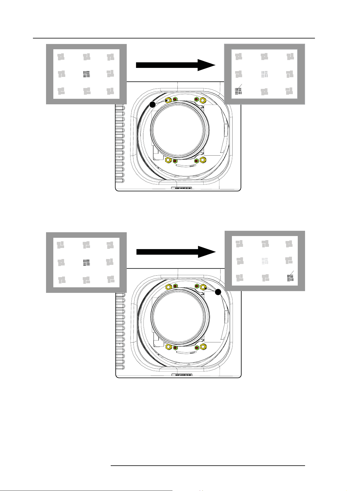
5. Lenses & lens holder
F
1
Image 5-18
Left bottom focusing
8. Continue with the right bottom corner. With a white paper, start at the screen and bring the paper forward. Can you focus the
image on the paper?
If yes, The focus plane is be fore the screen, adjust nut 2 by turning clockwise un til the image is focused on the screen.
If no, the focus plane is behind the screen, adjust nut 2 by tuning counter clockwise until the image is focused on the screen.
F
2
Image 5-19
Right bottom focusing
9. Continue with the right upper corner. With a white p aper, start at the screen and bring the paper forward. Can you focus the
image on the paper?
If yes, The focus plane is be fore the screen, adjust nut 3 by turning clockwise un til the image is focused on the screen.
If no, the focus plane is behind the screen, adjust nut 3 by tuning counter clockwise until the image is focused on the screen.
R59770495 DP2K-23B 30/04/2010
55
Page 62

5. Lenses & lens holder
3
Image 5-20
Corner focusing
10.Repeat from step 6 until the projected focus pattern is as sharp as possible in the center, left, right, top and bottom of the screen.
Start the fixation as follows:
a) Turn in set screw A, B and C until you feel a small resistance (set screws are just aga inst the lens plate).
b) Fasten lock nuts a, b and c.
c) Turn in set screw D until the image moves slightly. (This movement of the image will require tighter fi xation in step e, as the
nut must return the image to its original position.)
d) Fasten lock nut d.
e) Turn in nut 4 until the image returns to its or iginal position.
F
56
R59770495 DP2K-23B 30/04/2010
Page 63

6. INPUT & COMMUNICATION
Overview
• Introduction
• Local keypad o f the DP2K-23B projector
• Communication ports of the DP2K-23B projector
• About G ene ral Purpose Inputs & Outputs (GP IO)
• Source input ports of the DP2K-23B projector
• LED indications on the Integrated Cinema Processor module
6. Input & communication
R59770495 DP2K-23B 30/04/2010
57
Page 64

6. Input & communication
6.1 Introduction
General
The input & communication side of a DP2K-23B projector consists of a button module and 3 separate removable units, fan controller
module, Integrated cinema processor (ICP), HDSDI module and a Cinema controller m odule.
1
2
3
A
4
5
6
D
E
F
B
C
Image 6-1
Input and communication
A
Local keypad (button module)
B
Communication ports
DVI input ports
C
D
Socket for s ecurity key
E Fan controller module
F
USB ports (for future expansion) and
G SMPTE inputs (HDSDI)
CAUTION: A unit may only be removed by qualified service personnel. Removing a un it will result in an
authorization request upon starting.
G
LED indications for service purposes
58 R59770495 DP2K-23B 30/04/2010
Page 65

6.2 Local keypad of the D P2K-23B projector
Identification of the keys
2
1
3
4
5
1
2
3
4
6. Input & communication
6
7
8
Image 6-2
Local keypad
1 Marker area for macro name
2 Numeric keyboard
3 Standby key
4 Dowser open/close switch
5
Tes t pattern toggle switch
6 Lens shift up/down, left/right
7
Lens focus
8 Lens zoom
5
6
Numeric keys
All the numeric keys (2) of the local keypad have a blue backlight during normal operation. W hen the authorization process is
activated with the security key, the backlight color of the numeric keys 1 to 6 changes to orange. Each key can be linked to a macro
which allows you to setup the projector to your requirements with one push of a button. Note that each numeric key has a marker
area (1) where you can write down the name of the m acro.
Standby key
Standby key (3) switches ON or OFF the lamp and lamp electronics. The lamp cooling fans remain active for about 5 minutes. The
speed of the other fans is reduced. The backlight color of the standby key remains red in standby mode and changes to green in
operation mode.
Dowser key
The dowser key (4) opens or closes the dowser. The backlight color of the dowser key is green when the dowser is open and red
when the dowser is c losed.
Test pattern key
The test pattern key (5) gives you direct access to the internal test patterns of the projector.
Shift keys
The shift keys (6) allow you to shift the lens up/down or left/right.
Focus keys
The focus keys (7) allow you t
o focus the projected imag e on the screen.
Zoom keys
The zoom keys (8) allow you to zoom in or out the projected image on the screen.
R59770495 DP2K-23B 30/04/2010
59
Page 66

6. Input & communication
6.3 Communication ports of the DP2K-23B projector
Location of the communication ports
ICP
POWER
10 / 100 / 1000 BASE-T
1
2
3
1 2 3 4 5
Image 6-3
Communication ports
1 10/100/1000 base-T
2RS232IN
3 General purpose input/output (GPIO)
4 3D interface
5 Peripheral port
FMT
ICP
OS
SW
STAT
STAT
STAT
STAT
RS232 IN 3D INTERFACE PERIPHERAL PORT
DVI A DVI B
DVI INPUT
SEL
SYNC OK
CINEMA
SEL
SYNC OK
USB
ALT
CONT
OUT
GENERAL PURPOSE IN/OUT
USB
IN
SMPTE 292/424 IN
AB
SEL
SYNC OK
SEL
SYNC OK
10/100/1000 BASE-T
The DP2K-23B projector can be connected to a LAN (local area network) using one of the Ethernet ports (1). Once connected to the
LAN, users can access the projector from any location, inside or outside (if allowed) their company network using the Communicator
software. This software locates the pr ojector on the network if there is a DHCP server or the user can insert the correct IP-address to
access the projector. Once accessed, it is possible to check a nd manipulate all the projec tor settings. Remote diagnostics, control
and monitoring of the projector can then become a daily and very simple operation. The network connectivity allows detection of
potential errors and consequently improve service time.
As there is a need to daisy chain projectors when th ey are on an E the rnet network , an Ethernet switch is built in. the incoming
network is hereby available for the internal PC and for the next device in the chain. In this wa y a ’star’ network interconnection c an
be avoided. The switch use
d is a stand alone 10/100/1000Mbit Ethernet switch. This assures no influence on the network speed.
RS232 IN
This female DB-9 connector allows you to use a standard serial cable up to 10 meter to connect the touch panel interface with the
projector. Note that the RS 232 protocol is used on this connection.
RS232
An Electronic Industries Association (EIA) serial digital interface standard specifying the characteristics of the com m unication path between two devices using either D-SUB 9 pins or D-SUB 25 pins connectors. This standard is used for
relatively short-r
ange communications and does not specify balanced control lines. RS-232 is a serial control standard
with a set number of conductors, data rate, word length and type of c onnector to be used. The standard specifies component connection standards with regard to computer interface. It is also called RS-232-C, which is the third version
of the RS-232 sta
ndard, and is functionally identical to the CCITT V.24 standard. Logical ’0’ is > + 3V, Logical ’1’ is < -
3V. The range between -3V and +3V is the transition zone.
GENERAL PURPOSE IN/OUT
This 37 pin connector can be used to send or receive trigger signals from other devices. These input/output pins can be programmed
by macros created on the Communic ator touch panel. See user’s guide of the Touch panel, section Macro editor, for more information about thi
s functionality. Note that the General Purpose Inputs accept 24 volt maximum.
3D INTERFACE
Optional port.
60
R59770495 DP2K-23B 30/04/2010
Page 67

6. Input & communication
Can be used to connect external 3D devices to the projector. All signals necessary for 3D projection can be provided via this connector.
PERIPHERAL PORT
For future use.
R59770495 DP2K-23B 30/04/2010
61
Page 68

6. Input & communication
GPIn P
GPIn N
GPIn P
GPIn N
6.4 About General Purpose Inputs & Outputs (GPIO)
General Purpose inputs
Eight (8) opto-isolated general purpose inputs are available, six (6) free and 2 dedicated inputs. These inputs are used to trigger the
execution of macro files. For more explanation about the association of a macro to a GPI, consult the user guide of the Communicator
touch panel.
Input v oltage
The inputs can be directly driven from a TTL or CMOS output.
• Minimum voltage : V
• Maximum voltage : V
min
max
=3,3V
=24V
External power supply
When interfacing with contact closure outputs, an external power supply needs to be provided. Depending upon the configuration a
suitable pull-up resistor needs to be added as well.
Input to projector Internal projector
GPIn P
100R
+5V
to
+24V
Image 6-4
1k1
GPIn N
10k
Input to projector
+5V
to
+24V
Internal projector
GPIn P
100R
1k1
GPIn N
10k
Cables
When long cable connections are required the use of shielded c ables with twisted pairs is recommended. One twisted pair is to be
assigned to eac h GP Input pair.
How to make the connection
When the power supply used to provide the DC voltage is isolated from ground (for example in the case of an AC adapter) it is
recommended that the minus pole of that power supply is connected to gr ound (or to the projector chassis). This will avoid high
common mode vo ltages at the projector GP Inputs. If that same power supply is used for other parts of the system, take care not to
create ground loops. In any case when shielded c ables are used that shield should be connected to the projector chassis.
General Purpose outputs
Eight (8) opto-isolated outputs are available, where seven are general purpose and one for a fixed purpose. The seven general
purpose outputs can be controlled via so ftware while the fixed output provides the 3D output reference. When this output is closed
(current is flowing), then the system is OK.
About an output
The output can generate a falling edge, rising edge, toggle or continuous toggle.
• Generate Falling Edge – generate a falling edge on the external G PO port if the present state of the output is high. If the
present state of the external GPO is low, no edge will be generated.
• Generate Rising E dge – generate a rising edge on the ex ternal GPO p ort if the present state of the output is low. If the present
state of the external GPO is high, no edge will be generated.
• Generate Toggle – generate a toggle on the external GPO port. If the present state of the output is low, a rising edge will be
generated, followed by a falling edge. If the present state of the ou tput is high, a falling edge will be generated, followed b y a
rising edge.
• Generate Continuous Toggle - This command will generate a continuous toggle of the external GP O por t. This toggle will
continue until a Generate Falli
ng Edge, Generate Rising Edge,orGenerate Toggle command is received. The rate of toggle is
fixedto25Hz.
Output transistor
• Maximum output driving voltage : V
• Maximum current : I
max
=30mA
• Maximum power dissipation : 120 mW
max
=70V
62
R59770495 DP2K-23B 30/04/2010
Page 69

GPOut P
GPOut N
Output from projector Internal projector
GPOut P
Max 120 mW
GPOut N
Image 6-5
6. Input & communication
R59770495 DP2K-23B 30/04/2010 63
Page 70

6. Input & communication
6.5 Source input ports of the DP2K-23B projector
Location of the source input ports
FMT
1
2
Image 6-6
Inputs
10 / 100 / 1000 BASE-T
ICP
POWER
DVI A DVI B
3
1
SW
STAT
DVI INPUT
OS
STAT
SEL
SYNC OK
ICP
STAT
STAT
RS232 IN 3D INTERFACE PERIPHERAL PORT
2 3 4
CINEMA
SEL
SYNC OK
ALT
CONT
GENERAL PURPOSE IN/OUT
1 DVI-D input, port A, Single link + HDCP
2 DVI-D input, port B, Single link + HDCP
3 SMPTE 292/424 input, port A (maxim um cable length of 30 m allowed)
4 SMPTE 292/424 input, port B (maxim um cable length of 30 m allowed)
USB
OUT
USB
IN
SMPTE 292/424 IN
AB
SEL
SYNC OK
SEL
SYNC OK
SMPTE
Society of Motion Picture and Television Engineers - A global organization, based in the United States, that sets standards for baseband visual communications. This includes film as well as v ideo standards.
DVI
Digital Visual Interface is a display interface developed in response to the proliferation of digital flat panel displays.
The digital video connectivity standard that was developed by DDWG (Digital Display Work Group). This connection
standard offers two different connectors: one with 24 pins that handles digital video signals only, and one with 29 pins
that handles both digital and analog video. This standard u ses TMDS (Transition Minimize d Differential Signal) from
Silicon Image and DDC (Display Data Channel) from VESA (Video Electronics Standards Ass ociation).
DVI can be single or dual link.
DVI I nput formats
Input
Single DVI VESA (640x480)
Single DVI VESA (640x480)
Single DVI VESA (800x600)
Single DVI VESA (800x600)
Single DVI VESA
Single DVI VESA
Source
standard
(1024x768)
(1024x768)
Vertical rate
Scan type Color space Sampling Color depth
60 Prog ressive
72 Prog ressive
60 Prog ressive
72 Prog ressive
60 Prog ressive
70 Prog ressive
RGB
RGB
RGB
RGB
RGB
RGB
4:4:4 8 bit
4:4:4 8 bit
4:4:4 8 bit
4:4:4 8 bit
4:4:4 8 bit
4:4:4 8 bit
64 R59770495 DP2K-23B 30/04/2010
Page 71

6. Input & communication
Input
Single DVI VESA
Single D VI
Single D VI
Single D VI
Single D VI
Twin D VI
Twin D VI
Twin D VI
Twin D VI
Twin D VI
Source
standard
(1280x1024)
1280x720 60 Progressive
1920x1080 60 Progressive
2048x1080
1920x1080i
ACS
(2048x1080)
ACS
(2048x1080)
3D (2048x1080)
3D (2048x1080)
3D (2048x1080)
Vertical rate
60 Prog ressive
50/60
50/60
50/59.94
50/59.94
24 Prog ressive
25 Prog ressive
30 Prog ressive
Scan type Color space Sampling Color depth
Progressive
Interlaced
Progressive
Progressive
RGB
RGB
RGB
RGB
RGB
RGB
RGB
RGB
RGB
RGB
4:4:4 8 bit
4:4:4 8 bit
4:4:4 8 bit
4:4:4 8 bit
4:4:4 8 bit
4:4:4 10 bit
4:4:4 12 bit
4:4:4 2x8 bit
4:4:4 2x8 bit
4:4:4 2x8 bit
R59770495 DP2K-23B 30/04/2010 65
Page 72

6. Input & communication
6.6 LED indications on the Integrated Cinema Processor m odule
About the LEDs
FMT
ICP
OS
SW
STAT
STAT
STAT
STAT
3
2
DVI A DVI B
DVI INPUT
SEL
SYNC OK
5
4
RS232 IN 3D INTERFACE PERIPHERAL PORT
10 / 100 / 1000 BASE-T
1
2
ICP
POWER
1
3
Image 6-7
1 ICP is powered.
2 ICP software state, normal operation is green blinking.
3 ICP operating system state, normally full green.
4ICPFMTconfiguration state, normally full green.
5
ICP MAIN configuration state, normally full green.
6 CINEMA port selected. When on, LED 7 will be out.
7
ALTERNATIVE port selection. When on, LED 6 will be out.
8 USB, for future use.
ALT
CONT
CINEMA
6 7 8
SEL
SYNC OK
GENERAL PURPOSE IN/OUT
USB
OUT
USB
IN
SMPTE 292/424 IN
AB
SEL
SYNC OK
SEL
SYNC OK
66
R59770495 DP2K-23B 30/04/2010
Page 73

7. COMMUNICATOR TOUCH PANEL
Overview
• Introduction
• Installation of the touch panel interface
7. Communicator Touch Panel
R59770495 DP2K-23B 30/04/2010
67
Page 74

7. Communicator Touch Panel
7.1 Introduction
Communicator Touch Panel for digital cinema projectors
The Communicator Touch Panel is designed for multi-user command and control, the Communicator enables user s to learn quickly
and operate e fficiently - using an elegant and flexible touch panel interface. The interface’s commonality m eans that operators
can intuitively use any model in the product line, without restriction, and its user-friendly nature translates directly into a short and
enjoyable learning curve.
Image 7-1
Flexible touch panel interface
The touch panel interface can be mounted upon a swivel arm which easily fits on top of the DP2K-23B projector. One central locking
mechanism of the swivel arm allows an instant fixation of the touch panel interface in any position.
The touch panel interface can also be installed further away from the DP2K-23B projector. For that you can use a serial (RS232)
cable up to 10 meter or an Ethernet cable up t o 50 meter to allow a direct data communication between the DP2K-23B projector and
the Communicator Touch Panel.
The touch panel interface can also be connected with a Local Area Network (LAN) just like the DP2K-23B projector. In this case
both devices can communicate with each other as well.
The touch panel interface requires a +12 VDC voltage, 1,5 ampere. The use of a separate +12 VDC adaptor (1,5 ampere m inimum )
is required.
Parts location of the touch panel interface
A
B
D
C
Image 7-2
Communicator touch panel
A Touch screen
B Co mm unication panel
C Knob to operate central swivel clamp
DBaseofswivelarm
E Power input 12 VDC, 1.5A
F RS232 port (sub-D)
G Ethernet port (RJ45)
G
E
F
H
68
R59770495 DP2K-23B 30/04/2010
Page 75

7. Communicator Touch Panel
CAUTION: For more information about the use of the Communicator Touch Panel, consult its user guide.
R59770495 DP2K-23B 30/04/2010 69
Page 76

7. Communicator Touch Panel
7.2 Installation of the touch panel interface
Necessary tools
• 17 mm wrench
• 10 mm wrench
How to install the touch panel interface
1. Assemble the mounting plate and the swivel arm together as illustrated. First place the nut (N) up on the rod of the mounting
plate, then add the lock washer (L), then fasten the mounting plate and the swivel arm together. When the arm i
nut (N) against the arm to secure the position.
N
L
Image 7-3
Assemble swivel arm
2. Slide a washer (M) over the base of the swivel arm and Insert the base of the sw ivel arm into the mounting hole at the top of the
DP2K-23B projector as illustrated.
s mounted, tu rn
M
Image 7-5
Touch panel mounted
Image 7-4
Mount touch panel
3. Place the touch panel interface on the mounting plate of the swivel arm and fasten the two wing nuts (W) as illustrated.
70
R59770495 DP2K-23B 30/04/2010
Page 77

7. Communicator Touch Panel
W
Image 7-6
Mount touch panel
4. Connect the circular plug of the m ulti cable with the c ircular socket at the rear side of the DP2K-23B projector.
Image 7-7
5. Attach the multi cable to the swivel arm using the two Velcro strips.
6. Connect the DC plug, the RJ45 Ethernet plug and the D-SUB plug into their respective sockets on the touch panel interface.
Image 7-8
Connections
R59770495 DP2K-23B 30/04/2010 71
Page 78

7. Communicator Touch Panel
72 R59770495 DP2K-23B 30/04/2010
Page 79

8. Starting up
8. STARTING UP
About this chapter
This chapter contains the switch ON and sw itch OFF pr ocedures of the DP2K-23B. These procedures enumerate all the important
points which have to be checked prior to switching ON the projector. This is to ensure a safe start up of the projector.
Overview
• Switching ON the DP2K-23B projector
• Switching OFF the DP2K -23B digital projector
R59770495 DP2K-23B 30/04/2010
73
Page 80

8. Starting up
8.1 Switching ON the DP2K-23B projector
Howtoswitchon
1. Make sure that the D P 2K-23B projector is installed upon a stable pedestal. See chapter "Positioning the DP2K-23B at port
window", page 18.
2. Make sure that the exhaust system is properly installed. See chapter "Installation of the exhaust system ", page 21.
3. Make sure that the right lens is installed for your application. See cha pter "Lens selection", page 47.
4. Make sure that the lamp and lamp house are correctly installed. See chapter "Lamp & lamp house", page 27.
5. Make s ure the projector is correctly connected to the power net. See chapter "Connecting the projector with the power net", page
24.
6. Check if a video source is connected with the projector. See chapter "Source input ports of the DP2K-23B projector", page 64.
7. Check if the communicator touch panel is installed. See chapter "Communicator Touc h Panel", pag e 67..
8. Press the power switch to switch ON the projector. As a result the projector starts up in standby. So, the lamp is OFF and the
dowser closed. No internal pattern is selected. The communicator touch panel starts its initialization procedure.
- When ’0’ is visible, the projector is switched OFF.
- When ’1’ is visible, the projector is switched ON.
9. Press the STANDBY button on the local keypad or use the Communicator Touch Panel to activate the lamp.
10.Press the DOWSER button on the local keypad or use the Communicator Touch Panel to open the dowser. As a result the applied
source will be displayed.
CAUTION: See user’s guide of the Communicator To uch Panel to operate and control the DP2K-23B projector.
When for any reason a restart of the projector is required, the content server should be restarted also.
74 R59770495 DP2K-23B 30/04/2010
Page 81

8. Starting up
8.2 Switching OFF the DP2K-23B digital projector
How to switch OFF the DP2K-23B digital projector?
1. Press the standby button on the local keypad or use the Communicator Touch Panel to switch the projector from operation to
standby. As a result the lamp turns off but the fans remain turning to cool down the projector.
2. Let the projector cool down at least 5 m inutes or until the speed of the fans decreases.
3. Switch OFF the projector with the power switch.
R59770495 DP2K-23B 30/04/2010
75
Page 82

8. Starting up
76 R59770495 DP2K-23B 30/04/2010
Page 83

9. PROJECTOR REGISTRATION
Overview
• Introduction
• Download the certificate file
• Registration of new projector
• Update registration of an existing projector
9. Projector registration
R59770495 DP2K-23B 30/04/2010
77
Page 84

9. Projector registration
9.1 Introduction
Overview
The current projector is DCI compliant and should be re gistered by Barco. Therefore, the digital certificate inside the projector will
be used to secure encryption key communication between the projector and the rest of the theatre system (server and theatre management system). The film distributor will send keys to the theatre that are unique for the installed trusted digital cinema equipment
of that theatre. The film distributor will find its information about a theatre in the same database as where the projector is registered.
Barco plays as an intermediate station between the theatre and the film distributor.
Once a projector is registered, the uploaded data can be changed via the update procedure.
78
R59770495 DP2K-23B 30/04/2010
Page 85

9.2 Download the certificate file
How to download
1. Insert a USB stick in the Comm unicator touch panel.
2. On the touch panel, go via Installation > Advanced settings > Retrieve certificate.
9. Projector registration
Image 9-1
Download certificate
3. If the proposed filenameisOK,taponSave.
Otherwise, change fi rst the file n ame and tap then on Save.
4. Bring this file to a com puter with an Ethernet access and continue with the registration procedure.
R59770495 DP2K-23B 30/04/2010
79
Page 86

9. Projector registration
9.3 Registration of new projector
Possible login types
A projector can be r egistered by the following persons, each with its own login:
• installer
• owner
• Installer/owner
Depending on your login type, s ome steps are not nec essa ry in the registration procedure. F ollow the wizard as displayed on the
screen. The procedure below gives an overview of all possible steps which can be displayed.
How to register
1. Go to Barco’s Partnerzone on https://my.barco .com.
2. Login into the partnerzone.
If you are not yet re gistered, click on Sign in here and follow the instructions. With the created login and password, it is possible
to enter the partnerzone where you can upload the certificate.
When your login is cor rect, the digital cinema partnerzone start page is displayed.
Click Registration DC projector and select Regis ter a new DC projector.Thefirst registration page will be di
splayed.
Image 9-2
Start registration
3. C lick Browse to locate the certificate file. Select the fi le and click Open.
The fi le is filled out next to XML file. Click >> Next to continue.
Some checks are done on the certifica te file. When the file is correct a nd not yet uploaded, the next registration page is displayed.
4. Fill out the Technical Data page.
80
R59770495 DP2K-23B 30/04/2010
Page 87

9. Projector registration
Image 9-3
- Lenses: click on the drop down box and select the lens of the projector when a M25 lens or select Other lens when no M25
lens is used. When other lens is selected, an extra input field appears to fill out the lens type.
- Anamorphic lens: chec k when an anamorphic lens is available.
- Server brand: click on the drop down box and select the server brand name when in the list. Otherwise select Others and a
extra input field appears to enter the brand name.
- Screen width: enter the screen width value in meters or in inches. Wh en one of them is entered, the other value is calculated
automatically.
- Screen height: enter the screen height value in meters or in inches. When one of them is entered, the other value is calculated
automatically.
- Projector distance: enter the distance between the project
entered screen width.
- Screen gain: enter the gain of the screen used in the theatre.
- Number of seats: enter the number of seats in the theatre.
5. C lick Next >> to continue.
The location w indow opens with all available locations.
or and screen. The value is checked with the used lens and the
Image 9-4
Location window
6. If the location is in the list, select that location and click Next >> and continue to step 8.
R59770495 DP2K-23B 30/04/2010 81
Page 88

9. Projector registration
If the location is not in the list, click Add new and continue to next step.
7. Fill out a ll fields with an asterisk for Location, Contact person and Support contact.ClickNext >>.
Image 9-5
Add new location
The new location is added to the list of locations and is selected. Click Next >> to continue .
8. If the installer is in the list, selec t the installer and click Nex t >> to continue to step 10.
If th e installer is not in the list, click Add new and continue to next step.
Image 9-6
Select installer
9. Fill out the Company information, Contact person and Support contact. Click Next >> .
82
R59770495 DP2K-23B 30/04/2010
Page 89

9. Projector registration
Image 9-7
Add new inst a ller
The new installer is added to the list of installers and is selected. Click Next >> to continue to next step.
The owner input form appears.
10.If the owner is in the list, select the owner and click Next >> to finalize the registration.
If the owner is not in the list, click Add new and continue with next step.
Image 9-8
Select owner
11.Fill out the Company information, Contact person and Support contact. Click Next >>.
R59770495 DP2K-23B 30/04/2010
83
Page 90

9. Projector registration
Image 9-9
Add new owner
84 R59770495 DP2K-23B 30/04/2010
Page 91

9. Projector registration
The new owner is added to the list of owners and is selected. Click Next >> to finalize the registration.
The r egistration is completed. An E-mail will be sent to the person who is logged in.
Image 9-10
Registration successful
When an update of the data is ne cessary, due to e.g. location change or contact person change an update of
the registration is necessary. Start the update procedure.
R59770495 DP2K-23B 30/04/2010 85
Page 92

9. Projector registration
9.4 Update registration of an existing projector
When should it be used ?
An update of the registration of an ex isting projector should be done in e.g. one of the following cases:
• relocation of the projector
• new owner
• new contact person
• and when any of the registered data is changed.
How to update
1. First get a new certificate file. See "Download the certificate file", page 79.
2. Go to Barco’s Partnerzone on h
3. Login into the partnerzone.
Click Register DC projector and select Update DC projector.
The update page is displayed with your registered projectors.
ttps://secure.barco.com/digitalcinema/.
Image 9-11
Select projector to update
4. Select the projector for which the registration m ust be updated.
The installation address is displayed in Selection
Click >> Next to continue.
5. Browse to locate the certificate file. Select the file and click Open.
The file is fi lled out next to XML file. Click >> Next to continue. From now on the procedure is equal to those of the registration
of a new projector. Follow the steps as given in the wizard.
86
R59770495 DP2K-23B 30/04/2010
Page 93

10. Removal and installation of the projector covers
10. REMOVAL AND INS TALLATION OF THE PROJECTOR
COVERS
WARNING: All procedures in this chapter may only be performed by “qualified service technicians” .
WARNING: Disconnect the pow er to the circuit main terminals an d unplug the power cord at UPS INLET,
unless o therw ise specified in the procedure.
Overview
• Removal of the lamp cover
• Removal of the rear c over
• Removal of the input c over
• Removal of the front c over
• Removal of the side cover
• Installation of the front cover
• Installation of the input cover
• Installation of the lamp cover
• Installation of the rear cover
• Installation of the side cover
Location of the covers
5
1
Image 10-1
Location of the covers
1 Lamp cover
2 Input c over
3 Front cover
4
Side cover
5
Rear cover
4
2
3
All cover c an be individually removed.
R59770495 DP2K-23B 30/04/2010
87
Page 94

10. Removal and installation of the projector covers
10.1 Removal of the lamp cover
Necessary tools
Flat screwdriver
How to remove
1. Release both captive screws on top of the lamp cover.
Image 10-2
Lamp cover, fasting screws
2. Push both lock to each other to release the locks and pull at the same time the bottom side of the cover away form the projector.
1
1
Image 10-3
Lamp cover, locks
3. Take off the cover.
88
R59770495 DP2K-23B 30/04/2010
Page 95

10. Removal and installation of the projector covers
Image 10-4
Lamp cover, removal
R59770495 DP2K-23B 30/04/2010 89
Page 96

10. Removal and installation of the projector covers
10.2 Removal of the rear cover
Necessary tools
Flat screwdriver
How to remove
1. Release both captive screws almost at the bottom of the rear cover using a fl at screw driver (1).
2
2
1
1
Image 10-5
Rear housing removal
2. Remov e the rear cover of the projector doing the following:
a) gently pull out the top covers of the rear cover (2).
b) then move the rear cover away from the projecto
r.
90
R59770495 DP2K-23B 30/04/2010
Page 97

10. Removal and installation of the projector covers
10.3 Removal of the input cover
Necessary tools
Flat screwdriver
How to remove
1. Release both captive screws at the top of the input cover using a flat screw driver.
Image 10-6
Input cover, fixation
2. Remov e the input cover as follow:
a) Pull the bottom side of the cover to you until the cover is unlock ed.
b) Slide the full cover away from the projector
.
R59770495 DP2K-23B 30/04/2010
91
Page 98

10. Removal and installation of the projector covers
Image 10-7
Input cover removal
92 R59770495 DP2K-23B 30/04/2010
Page 99

10.4 Removal of the front cover
Necessary tools
Flat screwdriver
How to remove
1. Check if the lens is removed.
2. Remov e the rubber dust ring from the lens holder.
10. Removal and installation of the projector covers
Image 10-8
Release cover removal
3. Release the captive screw at the middle bottom of the front cover.
4. Remov e the front cover as follow:
a) standing in front of the projector, pull the top side of the cover to you until it is unlocked.
b) slide the cover away f rom the projector.
R59770495 DP2K-23B 30/04/2010
93
Page 100

10. Removal and installation of the projector covers
Image 10-9
Remove front cover
94 R59770495 DP2K-23B 30/04/2010
 Loading...