

Page 1
a`pJOMM
rлЙкЫл=dмбЗЙ
• Manual #: 26-0604010-00
• Revision: 00
Page 2

a`pJOMM==√==rлЙкЫл=dмбЗЙ
`зйукбЦЬн
© Barco. May 30, 2008
All rights reserved. No part of this document may be copied, reproduced or translated. It
shall not otherwise be recorded, transmitted or stored in a retrieval system without the prior
written consent of Barco.
kзнбЕЙ
Barco provides this manual “as is” without warranty of any kind, either expressed or
implied, including but not limited to the implied warranties or merchantability and fitness for
a particular purpose. Barco may make improvements and/or changes to the product(s) and/
or the program(s) described in this publication at any time without notice.
This publication could contain technical inaccuracies or typographical errors. Changes are
periodically made to the information in this publication; these changes are incorporated in
new editions of this publication.
cЙЗЙк~д=`зггмебЕ~нбзел=`зггбллбзе=Ec``F=pн~нЙгЙен
This equipment has been tested and found to comply with the limits for a class A digital
device, pursuant to Part 15 of the FCC rules. These limits are designed to provide
reasonable protection against harmful interference when the equipment is operated in a
commercial environment. This equipment generates, uses, and can radiate radio frequency
energy and, if not installed and used in accordance with the instruction manual, may cause
harmful interference to radio communications. Operation of this equipment in a residential
area may cause harmful interference, in which case the user will be responsible for
correcting any interference.
dм~к~енЙЙ=~еЗ=`згйЙел~нбзе
Barco provides a guarantee relating to perfect manufacturing as part of the legally
stipulated terms of guarantee. On receipt, the purchaser must immediately inspect all
delivered goods for damage incurred during transport, as well as for material and
manufacturing faults. Barco must be informed immediately in writing of any complaints.
The period of guarantee begins on the date of transfer of risks, in the case of special
systems and software on the date of commissioning, at latest 30 days after the transfer of
risks. In the event of justified notice of compliant, Barco can repair the fault or provide a
replacement at its own discretion within an appropriate period. If this measure proves to be
impossible or unsuccessful, the purchaser can demand a reduction in the purchase price or
cancellation of the contract. All other claims, in particular those relating to compensation for
direct or indirect damage, and also damage attributed to the operation of software as well
as to other services provided by Barco, being a component of the system or independent
service, will be deemed invalid provided the damage is not proven to be attributed to the
absence of properties guaranteed in writing or due to the intent or gross negligence or part
of Barco.
If the purchaser or a third party carries out modifications or repairs on goods delivered by
Barco, or if the goods are handled incorrectly, in p articular if the systems are commissioned
operated incorrectly or if, after the transfer of risks, the goods are subject to influences not
2 DCS-200 • User’s Guide
Page 3

agreed upon in the contract, all guarantee claims of the purchaser will be rendered invalid.
Not included in the guarantee coverage are system failures which are attributed to
programs or special electronic circuitry provided by the purchaser, e.g. interfaces. Normal
wear as well as normal maintenance are not subject to the guarantee provided by Barco
either.
The environmental conditions as well as the servicing and maintenance regulations
specified in this manual must be complied with by the customer.
qê~ÇÉã~êâë
Brand and product names mentioned in this manual may be trademarks, registered
trademarks or copyrights of their respective holders. All brand and product names
mentioned in this manual serve as comments or examples and are not to be understood as
advertising for the products or their manufactures.
`згй~еу=^ЗЗкЙлл
Barco Media and Entertainmen t
11101 Trade Center Drive
Rancho Cordova, California 95670
USA
• Phone: (916) 859-2500
• Toll Free: (888) 414-7226
• Fax: (916) 859-2515
• Website: www.barco.com
Barco N.V.
Noordlaan 5
8520 Kuurne
BELGIUM
• Phone: +32 56.36.82.11
• Fax: +32 56.35.16.51
• Website: www.barco.com
T echnical Support
• Tech Line: (866) 374-7878 — 24 hours per day, 7 days per week
DCS-200 • User’s Guide 3
Page 4

léÉê~íçêë=p~ÑÉíó=pìãã~êó
The general safety information in this summary is for operating personnel.
aз=kзн=oЙгзоЙ=`зоЙкл=зк=m~еЙдл
There are no user-serviceable parts within the unit. Removal of the top cover will expose
dangerous voltages. To avoid personal injury, do not remove the top cover. Do not operate
the unit without the cover installed.
mзпЙк=pзмкЕЙ
This product is intended to operate from a power source that will not apply more than 230
volts rms between the supply conductors or between both supply conductor and ground. A
protective ground connection by way of grounding conductor in the power cord is essential
for safe operation.
dкзмеЗбеЦ=нЬЙ=mкзЗмЕн
This product is grounded through the grounding conductor of the power cord. To avoid
electrical shock, plug the power cord into a properly wired receptacle before connecting to
the product input or output terminals. A protective-ground connection by way of the
grounding conductor in the power cord is essential for safe operation.
rлЙ=нЬЙ=mкзйЙк=mзпЙк=`зкЗ
Use only the power cord and connector specified for your product. Use only a power cord
that is in good condition. Refer cord and connector changes to qualified service personnel.
rлЙ=нЬЙ=mкзйЙк=cмлЙ
To avoid fire hazard, use only the fuse having identical type, voltage rating, and current
rating characteristics. Refer fuse replacement to quali fied service personnel.
aз=kзн=lйЙк~нЙ=бе=bсйдзлбоЙ=^нгзлйЬЙкЙл
To avoid explosion, do not operate this product in an explosive atmosphere.
4 DCS-200 • User’s Guide
Page 5
bимбйгЙен=j~квбеЦ=~еЗ=p~СЙну=qЙкгл=
t^okfkd
Highlights an operating procedure, practice, condition, statement, etc., which, if not strictly
observed, could result in injury to or death of personnel.
Note
Highlights an essential operating procedure, condition or
statement.
`^rqflk
The exclamation point within an equilateral triangle is intended to alert the user to the
presence of important operating and maintenance (servicing) instructions in the literature
accompanying the appliance.
^sboqfppbjbkq>
Le point d´exclamation dans un triangle equilatéral signale à alerter l´utilisateur qu´il y a
des instructions d´operation et d´entretien tres importantes dans la litérature qui
accompagne l´appareil.
slopf`eq
Ein Ausrufungszeichen innerhalb eines gleichwinkeligen Dreiecks dient dazu, den
Benutzer auf wichtige Bedienungs-und Wartungsanweisungen in der Dem Great
beiliegenden Literatur aufmerksam zu machen.
DCS-200 • User’s Guide 5
Page 6
`Ь~еЦЙ=eблнзку
The table below lists the changes to the DCS-200 User’s Guide.
Table 0-1. Change History
Rev Date ECP # Description Approved By
00 May 30, 2008 558656 DCS-200 User’s Guide R. Pellicano
6 DCS-200 • User’s Guide
Page 7

q~ДдЙ=зС=`зенЙенл
`Ü~éíÉê=N fенкзЗмЕнбзе =K=K=K=K=K=K=K=K=K=K=K=K=K=K=K=K=K=K=K=K=K=K=K=K=K=K=K=K=K=K=K=K=K=K=K=K=K=K=K=K=K=NP
In This Chapter. . . . . . . . . . . . . . . . . . . . . . . . . . . . . . . . . . . . . . . . . . . . . . . . 13
Chapter Structure. . . . . . . . . . . . . . . . . . . . . . . . . . . . . . . . . . . . . . . . . . . . . . 13
How to Use This Guide. . . . . . . . . . . . . . . . . . . . . . . . . . . . . . . . . . . . . . . . . . 14
Navigating . . . . . . . . . . . . . . . . . . . . . . . . . . . . . . . . . . . . . . . . . . . . . . 14
Table of Contents and Index . . . . . . . . . . . . . . . . . . . . . . . . . . . . . . . . 14
Conventions . . . . . . . . . . . . . . . . . . . . . . . . . . . . . . . . . . . . . . . . . . . . . . . . . . 14
About the DCS-200 . . . . . . . . . . . . . . . . . . . . . . . . . . . . . . . . . . . . . . . . . . . . 15
Overview . . . . . . . . . . . . . . . . . . . . . . . . . . . . . . . . . . . . . . . . . . . . . . . 15
Features. . . . . . . . . . . . . . . . . . . . . . . . . . . . . . . . . . . . . . . . . . . . . . . . 15
A Word About HDCP. . . . . . . . . . . . . . . . . . . . . . . . . . . . . . . . . . . . . . 17
Connectivity Diagram . . . . . . . . . . . . . . . . . . . . . . . . . . . . . . . . . . . . . . . . . . . 18
Application Questions. . . . . . . . . . . . . . . . . . . . . . . . . . . . . . . . . . . . . . . . . . . 18
`Ü~éíÉê=O e~кЗп~кЙ=lкбЙен~нбзе =K=K=K=K=K=K=K=K=K=K=K=K=K=K=K=K=K=K=K=K=K=K=K=K=K=K=K=K=K=K=K=K=NV
In This Chapter. . . . . . . . . . . . . . . . . . . . . . . . . . . . . . . . . . . . . . . . . . . . . . . . 19
DCS-200 Front Panel. . . . . . . . . . . . . . . . . . . . . . . . . . . . . . . . . . . . . . . . . . . 20
Display Section . . . . . . . . . . . . . . . . . . . . . . . . . . . . . . . . . . . . . . . . . . 21
Inputs Section . . . . . . . . . . . . . . . . . . . . . . . . . . . . . . . . . . . . . . . . . . . 22
Effects Section. . . . . . . . . . . . . . . . . . . . . . . . . . . . . . . . . . . . . . . . . . . 23
Take . . . . . . . . . . . . . . . . . . . . . . . . . . . . . . . . . . . . . . . . . . . . . . . . . . 24
DCS-200 Rear Panel . . . . . . . . . . . . . . . . . . . . . . . . . . . . . . . . . . . . . . . . . . . 25
`Ü~éíÉê=P fåëí~ää~íáçå =K=K=K=K=K=K=K=K=K=K=K=K=K=K=K=K=K=K=K=K=K=K=K=K=K=K=K=K=K=K=K=K=K=K=K=K=K=K=K=K=K=K=OT
In This Chapter. . . . . . . . . . . . . . . . . . . . . . . . . . . . . . . . . . . . . . . . . . . . . . . . 27
Safety Precautions . . . . . . . . . . . . . . . . . . . . . . . . . . . . . . . . . . . . . . . . . . . . . 28
Unpacking and Inspection . . . . . . . . . . . . . . . . . . . . . . . . . . . . . . . . . . . . . . . 28
Site Preparation . . . . . . . . . . . . . . . . . . . . . . . . . . . . . . . . . . . . . . . . . . . . . . . 28
Cable and Adapter Information. . . . . . . . . . . . . . . . . . . . . . . . . . . . . . . . . . . . 28
Rack-Mount Installation . . . . . . . . . . . . . . . . . . . . . . . . . . . . . . . . . . . . . . . . . 29
Power Installation. . . . . . . . . . . . . . . . . . . . . . . . . . . . . . . . . . . . . . . . . . . . . . 29
Power Cord/Line Voltage Selection. . . . . . . . . . . . . . . . . . . . . . . . . . . 30
Signal Installation . . . . . . . . . . . . . . . . . . . . . . . . . . . . . . . . . . . . . . . . . . . . . . 31
Format Connection Table. . . . . . . . . . . . . . . . . . . . . . . . . . . . . . . . . . . . . . . . 32
`Ü~éíÉê=Q léÉê~íáçåK=K=K=K=K=K=K=K=K=K=K=K=K=K=K=K=K=K=K=K=K=K=K=K=K=K=K=K=K=K=K=K=K=K=K=K=K=K=K=K=K=K=K=K=PP
In This Chapter. . . . . . . . . . . . . . . . . . . . . . . . . . . . . . . . . . . . . . . . . . . . . . . . 33
Control Overview . . . . . . . . . . . . . . . . . . . . . . . . . . . . . . . . . . . . . . . . . . . . . . 34
Power-Up Initialization . . . . . . . . . . . . . . . . . . . . . . . . . . . . . . . . . . . . . . . . . . 34
Button States . . . . . . . . . . . . . . . . . . . . . . . . . . . . . . . . . . . . . . . . . . . . . . . . . 35
DCS-200 • User’s Guide 7
Page 8

Table of Contents
Quick Setup and Operations . . . . . . . . . . . . . . . . . . . . . . . . . . . . . . . . . . . . . 36
Menu Tree . . . . . . . . . . . . . . . . . . . . . . . . . . . . . . . . . . . . . . . . . . . . . . . . . . . 38
Using the Menu System . . . . . . . . . . . . . . . . . . . . . . . . . . . . . . . . . . . . . . . . . 39
Quick Function Reference . . . . . . . . . . . . . . . . . . . . . . . . . . . . . . . . . . . . . . . 41
Status Menu . . . . . . . . . . . . . . . . . . . . . . . . . . . . . . . . . . . . . . . . . . . . . . . . . . 44
Using the Setup Menu . . . . . . . . . . . . . . . . . . . . . . . . . . . . . . . . . . . . . . . . . . 46
Trans Time. . . . . . . . . . . . . . . . . . . . . . . . . . . . . . . . . . . . . . . . . . . . . . 47
Output Menu . . . . . . . . . . . . . . . . . . . . . . . . . . . . . . . . . . . . . . . . . . . . 47
Output Format. . . . . . . . . . . . . . . . . . . . . . . . . . . . . . . . . . . . 48
Test Pattern. . . . . . . . . . . . . . . . . . . . . . . . . . . . . . . . . . . . . . 48
Sync Setup . . . . . . . . . . . . . . . . . . . . . . . . . . . . . . . . . . . . . . 49
Gamma . . . . . . . . . . . . . . . . . . . . . . . . . . . . . . . . . . . . . . . . . 49
Save Output Config. . . . . . . . . . . . . . . . . . . . . . . . . . . . . . . . 49
Preview Menu . . . . . . . . . . . . . . . . . . . . . . . . . . . . . . . . . . . . . . . . . . . 50
Output Src. . . . . . . . . . . . . . . . . . . . . . . . . . . . . . . . . . . . . . . 51
Output Format (Preview). . . . . . . . . . . . . . . . . . . . . . . . . . . . 51
Test Patterns (Preview). . . . . . . . . . . . . . . . . . . . . . . . . . . . . 52
Preview Sync. . . . . . . . . . . . . . . . . . . . . . . . . . . . . . . . . . . . . 52
Save (Preview) . . . . . . . . . . . . . . . . . . . . . . . . . . . . . . . . . . . 53
Input Menu. . . . . . . . . . . . . . . . . . . . . . . . . . . . . . . . . . . . . . . . . . . . . . 53
Input Format . . . . . . . . . . . . . . . . . . . . . . . . . . . . . . . . . . . . . 55
Adjust On. . . . . . . . . . . . . . . . . . . . . . . . . . . . . . . . . . . . . . . . 55
Type . . . . . . . . . . . . . . . . . . . . . . . . . . . . . . . . . . . . . . . . . . . 56
Colorspace . . . . . . . . . . . . . . . . . . . . . . . . . . . . . . . . . . . . . . 56
Background. . . . . . . . . . . . . . . . . . . . . . . . . . . . . . . . . . . . . . 57
Timing Adjust. . . . . . . . . . . . . . . . . . . . . . . . . . . . . . . . . . . . . 57
Image Adjust . . . . . . . . . . . . . . . . . . . . . . . . . . . . . . . . . . . . . 60
Contrast. . . . . . . . . . . . . . . . . . . . . . . . . . . . . . . . . . . . . . . . . 61
Brightness . . . . . . . . . . . . . . . . . . . . . . . . . . . . . . . . . . . . . . . 61
Color Balance . . . . . . . . . . . . . . . . . . . . . . . . . . . . . . . . . . . . 62
Processing. . . . . . . . . . . . . . . . . . . . . . . . . . . . . . . . . . . . . . . 63
About Input Configuration Files. . . . . . . . . . . . . . . . . . . . . . . 63
Reset Config . . . . . . . . . . . . . . . . . . . . . . . . . . . . . . . . . . . . . 64
Save Config. . . . . . . . . . . . . . . . . . . . . . . . . . . . . . . . . . . . . . 64
Delete Config. . . . . . . . . . . . . . . . . . . . . . . . . . . . . . . . . . . . . 65
Recall Config. . . . . . . . . . . . . . . . . . . . . . . . . . . . . . . . . . . . . 66
Key Setup Menu . . . . . . . . . . . . . . . . . . . . . . . . . . . . . . . . . . . . . . . . . 67
LOGO Setup Menu . . . . . . . . . . . . . . . . . . . . . . . . . . . . . . . . . . . . . . . 69
User Preference. . . . . . . . . . . . . . . . . . . . . . . . . . . . . . . . . . . . . . . . . . 70
In Auto Acquire . . . . . . . . . . . . . . . . . . . . . . . . . . . . . . . . . . . 70
Auto Input Config. . . . . . . . . . . . . . . . . . . . . . . . . . . . . . . . . . 71
Auto Input Save. . . . . . . . . . . . . . . . . . . . . . . . . . . . . . . . . . . 72
Auto Take . . . . . . . . . . . . . . . . . . . . . . . . . . . . . . . . . . . . . . . 72
Black Auto Take . . . . . . . . . . . . . . . . . . . . . . . . . . . . . . . . . . 72
Key Auto Take. . . . . . . . . . . . . . . . . . . . . . . . . . . . . . . . . . . . 72
Menu Context . . . . . . . . . . . . . . . . . . . . . . . . . . . . . . . . . . . . 72
System Menu. . . . . . . . . . . . . . . . . . . . . . . . . . . . . . . . . . . . . . . . . . . . 73
VFD Brightness. . . . . . . . . . . . . . . . . . . . . . . . . . . . . . . . . . . 73
Ethernet. . . . . . . . . . . . . . . . . . . . . . . . . . . . . . . . . . . . . . . . . 74
Serial Setup. . . . . . . . . . . . . . . . . . . . . . . . . . . . . . . . . . . . . . 76
EDID Setup . . . . . . . . . . . . . . . . . . . . . . . . . . . . . . . . . . . . . . 77
DVI Cable Equalization . . . . . . . . . . . . . . . . . . . . . . . . . . . . . 79
8 DCS-200 • User’s Guide
Page 9

Table of Contents
File Association Menu. . . . . . . . . . . . . . . . . . . . . . . . . . . . . . 79
Temperature . . . . . . . . . . . . . . . . . . . . . . . . . . . . . . . . . . . . . 80
Diagnostics . . . . . . . . . . . . . . . . . . . . . . . . . . . . . . . . . . . . . . 81
Save System State . . . . . . . . . . . . . . . . . . . . . . . . . . . . . . . . 81
Tech Support. . . . . . . . . . . . . . . . . . . . . . . . . . . . . . . . . . . . . . . . . . . . 82
Factory Reset . . . . . . . . . . . . . . . . . . . . . . . . . . . . . . . . . . . . . . . . . . . 82
Using Inputs . . . . . . . . . . . . . . . . . . . . . . . . . . . . . . . . . . . . . . . . . . . . . . . . . . 84
Input Selection Rules. . . . . . . . . . . . . . . . . . . . . . . . . . . . . . . . . . . . . . 84
Flip-flop Mode . . . . . . . . . . . . . . . . . . . . . . . . . . . . . . . . . . . . . . . . . . . 85
Understanding Auto Acquire . . . . . . . . . . . . . . . . . . . . . . . . . . . . . . . . 86
Using HDCP . . . . . . . . . . . . . . . . . . . . . . . . . . . . . . . . . . . . . . . . . . . . 86
Using the LOGO. . . . . . . . . . . . . . . . . . . . . . . . . . . . . . . . . . . . . . . . . . . . . . . 88
Saving a Logo . . . . . . . . . . . . . . . . . . . . . . . . . . . . . . . . . . . . . . . . . . . 89
Transitioning to a Logo . . . . . . . . . . . . . . . . . . . . . . . . . . . . . . . . . . . . 90
Deleting a Logo . . . . . . . . . . . . . . . . . . . . . . . . . . . . . . . . . . . . . . . . . . 90
Using Freeze . . . . . . . . . . . . . . . . . . . . . . . . . . . . . . . . . . . . . . . . . . . . . . . . . 92
Using Black. . . . . . . . . . . . . . . . . . . . . . . . . . . . . . . . . . . . . . . . . . . . . . . . . . . 93
Black Auto Take Off. . . . . . . . . . . . . . . . . . . . . . . . . . . . . . . . . . . . . . . 93
Black Auto Take On. . . . . . . . . . . . . . . . . . . . . . . . . . . . . . . . . . . . . . . 94
Using Keys . . . . . . . . . . . . . . . . . . . . . . . . . . . . . . . . . . . . . . . . . . . . . . . . . . . 95
Introduction to Keying . . . . . . . . . . . . . . . . . . . . . . . . . . . . . . . . . . . . . 95
Performing a Key. . . . . . . . . . . . . . . . . . . . . . . . . . . . . . . . . . . . . . . . . 96
Key Auto Take Off. . . . . . . . . . . . . . . . . . . . . . . . . . . . . . . . . 96
Key Auto Take On. . . . . . . . . . . . . . . . . . . . . . . . . . . . . . . . . 97
Key Transition Combinations. . . . . . . . . . . . . . . . . . . . . . . . . . . . . . . . 97
Mix Key Up . . . . . . . . . . . . . . . . . . . . . . . . . . . . . . . . . . . . . . 98
Mix Key Down . . . . . . . . . . . . . . . . . . . . . . . . . . . . . . . . . . . . 98
Mix Source plus Key Up . . . . . . . . . . . . . . . . . . . . . . . . . . . . 98
Mix Source plus Key Down . . . . . . . . . . . . . . . . . . . . . . . . . . 99
Source Transition Under Key . . . . . . . . . . . . . . . . . . . . . . . . 99
Fade to Black from Source plus Key. . . . . . . . . . . . . . . . . . 100
Fade up from Black to Source plus Key . . . . . . . . . . . . . . . 100
Understanding Front-Panel Lockout. . . . . . . . . . . . . . . . . . . . . . . . . . . . . . . 101
Full Lockout Mode . . . . . . . . . . . . . . . . . . . . . . . . . . . . . . . . . . . . . . . 101
Executive Lockout Mode . . . . . . . . . . . . . . . . . . . . . . . . . . . . . . . . . . 101
`Ü~éíÉê=R drf=lйЙк~нбзел =K=K=K=K=K=K=K=K=K=K=K=K=K=K=K=K=K=K=K=K=K=K=K=K=K=K=K=K=K=K=K=K=K=K=K=K=KNMP
In This Chapter. . . . . . . . . . . . . . . . . . . . . . . . . . . . . . . . . . . . . . . . . . . . . . . 103
GUI Connection and Launch . . . . . . . . . . . . . . . . . . . . . . . . . . . . . . . . . . . . 104
GUI Operations. . . . . . . . . . . . . . . . . . . . . . . . . . . . . . . . . . . . . . . . . . . . . . . 106
`Ü~éíÉê=S réÖê~ÇáåÖ=pçÑíï~êÉK=K=K=K=K=K=K=K=K=K=K=K=K=K=K=K=K=K=K=K=K=K=K=K=K=K=K=K=K=K=K=K=KNMT
In This Chapter. . . . . . . . . . . . . . . . . . . . . . . . . . . . . . . . . . . . . . . . . . . . . . . 107
Software Upgrade Overview. . . . . . . . . . . . . . . . . . . . . . . . . . . . . . . . . . . . . 108
Hardware Requirements. . . . . . . . . . . . . . . . . . . . . . . . . . . . . . . . . . . . . . . . 108
Software Requirements . . . . . . . . . . . . . . . . . . . . . . . . . . . . . . . . . . . . . . . . 108
Downloading Software . . . . . . . . . . . . . . . . . . . . . . . . . . . . . . . . . . . . . . . . . 109
Via FTP Site. . . . . . . . . . . . . . . . . . . . . . . . . . . . . . . . . . . . . . . . . . . . 109
Via Web Site . . . . . . . . . . . . . . . . . . . . . . . . . . . . . . . . . . . . . . . . . . . 109
Ethernet Upgrade Method . . . . . . . . . . . . . . . . . . . . . . . . . . . . . . . . . . . . . . 110
DCS-200 • User’s Guide 9
Page 10

Table of Contents
Troubleshooting Ethernet Communication . . . . . . . . . . . . . . . . . . . . 113
^ййЙеЗбс=^= pйЙЕбСбЕ~нбзелK=K=K=K=K=K=K=K=K=K=K=K=K=K=K=K=K=K=K=K=K=K=K=K=K=K=K=K=K=K=K=K=K=K=K=K=K=K=KNNR
In This Appendix. . . . . . . . . . . . . . . . . . . . . . . . . . . . . . . . . . . . . . . . . . . . . . 115
Input Specifications . . . . . . . . . . . . . . . . . . . . . . . . . . . . . . . . . . . . . . . . . . . 116
Output Specifications . . . . . . . . . . . . . . . . . . . . . . . . . . . . . . . . . . . . . . . . . . 116
Physical and Electrical Specifications . . . . . . . . . . . . . . . . . . . . . . . . . . . . . 117
Communications Specifications . . . . . . . . . . . . . . . . . . . . . . . . . . . . . . . . . . 117
Agency Specifications . . . . . . . . . . . . . . . . . . . . . . . . . . . . . . . . . . . . . . . . . 117
Pinouts . . . . . . . . . . . . . . . . . . . . . . . . . . . . . . . . . . . . . . . . . . . . . . . . . . . . . 118
Analog 15-pin D Connector . . . . . . . . . . . . . . . . . . . . . . . . . . . . . . . . 118
DVI-I Connector. . . . . . . . . . . . . . . . . . . . . . . . . . . . . . . . . . . . . . . . . 119
Ethernet Connector . . . . . . . . . . . . . . . . . . . . . . . . . . . . . . . . . . . . . . 120
Serial Connector . . . . . . . . . . . . . . . . . . . . . . . . . . . . . . . . . . . . . . . . 121
Format Table . . . . . . . . . . . . . . . . . . . . . . . . . . . . . . . . . . . . . . . . . . . . . . . . 122
^ййЙеЗбс=_= oЙгзнЙ=`зенкзд=K=K=K=K=K=K=K=K=K=K=K=K=K=K=K=K=K=K=K=K=K=K=K=K=K=K=K=K=K=K=K=K=K=K=K=K=KNOT
In This Appendix. . . . . . . . . . . . . . . . . . . . . . . . . . . . . . . . . . . . . . . . . . . . . . 127
Communicating with DCS-200 . . . . . . . . . . . . . . . . . . . . . . . . . . . . . . . . . . . 127
Command Protocol. . . . . . . . . . . . . . . . . . . . . . . . . . . . . . . . . . . . . . . . . . . . 128
Command Responses. . . . . . . . . . . . . . . . . . . . . . . . . . . . . . . . . . . . 128
Query Options . . . . . . . . . . . . . . . . . . . . . . . . . . . . . . . . . . . . . . . . . . 128
IBRT . . . . . . . . . . . . . . . . . . . . . . . . . . . . . . . . . . . . . . . . . . 128
Error Codes . . . . . . . . . . . . . . . . . . . . . . . . . . . . . . . . . . . . . . . . . . . . . . . . . 130
Error Codes: General Failures . . . . . . . . . . . . . . . . . . . . . . . . . . . . . 130
Error Codes: No Error. . . . . . . . . . . . . . . . . . . . . . . . . . . . . . . . . . . . 130
DCS-200 Command List. . . . . . . . . . . . . . . . . . . . . . . . . . . . . . . . . . . . . . . . 131
Remote Commands . . . . . . . . . . . . . . . . . . . . . . . . . . . . . . . . . . . . . . . . . . . 134
Ethernet Commands . . . . . . . . . . . . . . . . . . . . . . . . . . . . . . . . . . . . . 134
DHCP . . . . . . . . . . . . . . . . . . . . . . . . . . . . . . . . . . . . . . . . . 134
EMAC . . . . . . . . . . . . . . . . . . . . . . . . . . . . . . . . . . . . . . . . . 134
GATEWAY . . . . . . . . . . . . . . . . . . . . . . . . . . . . . . . . . . . . . 135
IP. . . . . . . . . . . . . . . . . . . . . . . . . . . . . . . . . . . . . . . . . . . . . 135
SUBNET . . . . . . . . . . . . . . . . . . . . . . . . . . . . . . . . . . . . . . . 135
Input Commands . . . . . . . . . . . . . . . . . . . . . . . . . . . . . . . . . . . . . . . . 135
ACQ. . . . . . . . . . . . . . . . . . . . . . . . . . . . . . . . . . . . . . . . . . . 135
AUTOACQ. . . . . . . . . . . . . . . . . . . . . . . . . . . . . . . . . . . . . . 135
BACKGND. . . . . . . . . . . . . . . . . . . . . . . . . . . . . . . . . . . . . . 136
BLKVID . . . . . . . . . . . . . . . . . . . . . . . . . . . . . . . . . . . . . . . . 136
CBLEQ . . . . . . . . . . . . . . . . . . . . . . . . . . . . . . . . . . . . . . . . 136
EDID . . . . . . . . . . . . . . . . . . . . . . . . . . . . . . . . . . . . . . . . . . 136
EDIDTYPE . . . . . . . . . . . . . . . . . . . . . . . . . . . . . . . . . . . . . 137
FREEZE . . . . . . . . . . . . . . . . . . . . . . . . . . . . . . . . . . . . . . . 137
IADJ. . . . . . . . . . . . . . . . . . . . . . . . . . . . . . . . . . . . . . . . . . . 137
IAR . . . . . . . . . . . . . . . . . . . . . . . . . . . . . . . . . . . . . . . . . . . 137
IAUTOC . . . . . . . . . . . . . . . . . . . . . . . . . . . . . . . . . . . . . . . 138
IAVAIL. . . . . . . . . . . . . . . . . . . . . . . . . . . . . . . . . . . . . . . . . 138
IBRT . . . . . . . . . . . . . . . . . . . . . . . . . . . . . . . . . . . . . . . . . . 138
ICDEL . . . . . . . . . . . . . . . . . . . . . . . . . . . . . . . . . . . . . . . . . 139
10 DCS-200 • User’s Guide
Page 11

Table of Contents
ICNT . . . . . . . . . . . . . . . . . . . . . . . . . . . . . . . . . . . . . . . . . . 139
ICPHO. . . . . . . . . . . . . . . . . . . . . . . . . . . . . . . . . . . . . . . . . 139
ICREC . . . . . . . . . . . . . . . . . . . . . . . . . . . . . . . . . . . . . . . . 139
ICRST . . . . . . . . . . . . . . . . . . . . . . . . . . . . . . . . . . . . . . . . . 140
ICSAV . . . . . . . . . . . . . . . . . . . . . . . . . . . . . . . . . . . . . . . . . 140
ICSP . . . . . . . . . . . . . . . . . . . . . . . . . . . . . . . . . . . . . . . . . . 140
IHATV . . . . . . . . . . . . . . . . . . . . . . . . . . . . . . . . . . . . . . . . . 140
IHCROP . . . . . . . . . . . . . . . . . . . . . . . . . . . . . . . . . . . . . . . 141
IHPAN . . . . . . . . . . . . . . . . . . . . . . . . . . . . . . . . . . . . . . . . . 141
IHPOS. . . . . . . . . . . . . . . . . . . . . . . . . . . . . . . . . . . . . . . . . 141
IHTOTAL. . . . . . . . . . . . . . . . . . . . . . . . . . . . . . . . . . . . . . . 142
IHUE . . . . . . . . . . . . . . . . . . . . . . . . . . . . . . . . . . . . . . . . . . 142
IMAP . . . . . . . . . . . . . . . . . . . . . . . . . . . . . . . . . . . . . . . . . . 142
IRBRT . . . . . . . . . . . . . . . . . . . . . . . . . . . . . . . . . . . . . . . . . 142
IRCNT . . . . . . . . . . . . . . . . . . . . . . . . . . . . . . . . . . . . . . . . . 143
IRES . . . . . . . . . . . . . . . . . . . . . . . . . . . . . . . . . . . . . . . . . . 143
ISAT . . . . . . . . . . . . . . . . . . . . . . . . . . . . . . . . . . . . . . . . . . 143
ISEL. . . . . . . . . . . . . . . . . . . . . . . . . . . . . . . . . . . . . . . . . . . 144
ISLICE . . . . . . . . . . . . . . . . . . . . . . . . . . . . . . . . . . . . . . . . 144
ISMP . . . . . . . . . . . . . . . . . . . . . . . . . . . . . . . . . . . . . . . . . . 144
ISYNC . . . . . . . . . . . . . . . . . . . . . . . . . . . . . . . . . . . . . . . . . 145
ITYPE . . . . . . . . . . . . . . . . . . . . . . . . . . . . . . . . . . . . . . . . . 145
IVATV . . . . . . . . . . . . . . . . . . . . . . . . . . . . . . . . . . . . . . . . . 146
IVCROP . . . . . . . . . . . . . . . . . . . . . . . . . . . . . . . . . . . . . . . 146
IVPAN . . . . . . . . . . . . . . . . . . . . . . . . . . . . . . . . . . . . . . . . . 146
IVPOS . . . . . . . . . . . . . . . . . . . . . . . . . . . . . . . . . . . . . . . . . 146
IVTOTAL . . . . . . . . . . . . . . . . . . . . . . . . . . . . . . . . . . . . . . . 147
PCOMP . . . . . . . . . . . . . . . . . . . . . . . . . . . . . . . . . . . . . . . 147
TAKE. . . . . . . . . . . . . . . . . . . . . . . . . . . . . . . . . . . . . . . . . . 147
Output Commands. . . . . . . . . . . . . . . . . . . . . . . . . . . . . . . . . . . . . . . 147
BLACK . . . . . . . . . . . . . . . . . . . . . . . . . . . . . . . . . . . . . . . . 147
OAVAIL . . . . . . . . . . . . . . . . . . . . . . . . . . . . . . . . . . . . . . . . 147
OCSAV . . . . . . . . . . . . . . . . . . . . . . . . . . . . . . . . . . . . . . . . 147
OGM . . . . . . . . . . . . . . . . . . . . . . . . . . . . . . . . . . . . . . . . . . 148
ORBM . . . . . . . . . . . . . . . . . . . . . . . . . . . . . . . . . . . . . . . . . 148
ORES . . . . . . . . . . . . . . . . . . . . . . . . . . . . . . . . . . . . . . . . . 148
OSRC . . . . . . . . . . . . . . . . . . . . . . . . . . . . . . . . . . . . . . . . . 149
OSYNC . . . . . . . . . . . . . . . . . . . . . . . . . . . . . . . . . . . . . . . . 149
OTPM . . . . . . . . . . . . . . . . . . . . . . . . . . . . . . . . . . . . . . . . . 149
OTPT . . . . . . . . . . . . . . . . . . . . . . . . . . . . . . . . . . . . . . . . . 150
System Commands . . . . . . . . . . . . . . . . . . . . . . . . . . . . . . . . . . . . . . 151
AUTOCFG . . . . . . . . . . . . . . . . . . . . . . . . . . . . . . . . . . . . . 151
AUTOSAVE . . . . . . . . . . . . . . . . . . . . . . . . . . . . . . . . . . . . 151
AUTOTAKE . . . . . . . . . . . . . . . . . . . . . . . . . . . . . . . . . . . . 151
BLKTRAN . . . . . . . . . . . . . . . . . . . . . . . . . . . . . . . . . . . . . . 151
CONTEXT . . . . . . . . . . . . . . . . . . . . . . . . . . . . . . . . . . . . . 151
DIAG . . . . . . . . . . . . . . . . . . . . . . . . . . . . . . . . . . . . . . . . . . 152
DIAGD. . . . . . . . . . . . . . . . . . . . . . . . . . . . . . . . . . . . . . . . . 152
ISTAT . . . . . . . . . . . . . . . . . . . . . . . . . . . . . . . . . . . . . . . . . 152
LCLR. . . . . . . . . . . . . . . . . . . . . . . . . . . . . . . . . . . . . . . . . . 152
LDMP . . . . . . . . . . . . . . . . . . . . . . . . . . . . . . . . . . . . . . . . . 152
LFEN. . . . . . . . . . . . . . . . . . . . . . . . . . . . . . . . . . . . . . . . . . 153
DCS-200 • User’s Guide 11
Page 12

Table of Contents
LINT. . . . . . . . . . . . . . . . . . . . . . . . . . . . . . . . . . . . . . . . . . . 153
LOCKOUT. . . . . . . . . . . . . . . . . . . . . . . . . . . . . . . . . . . . . . 153
OSTAT . . . . . . . . . . . . . . . . . . . . . . . . . . . . . . . . . . . . . . . . 153
PREVIEW . . . . . . . . . . . . . . . . . . . . . . . . . . . . . . . . . . . . . . 153
PROGRAM . . . . . . . . . . . . . . . . . . . . . . . . . . . . . . . . . . . . . 154
RESET . . . . . . . . . . . . . . . . . . . . . . . . . . . . . . . . . . . . . . . . 154
SAVE . . . . . . . . . . . . . . . . . . . . . . . . . . . . . . . . . . . . . . . . . 154
SERIAL . . . . . . . . . . . . . . . . . . . . . . . . . . . . . . . . . . . . . . . . 154
TEMP . . . . . . . . . . . . . . . . . . . . . . . . . . . . . . . . . . . . . . . . . 155
TRNTIME . . . . . . . . . . . . . . . . . . . . . . . . . . . . . . . . . . . . . . 155
VER. . . . . . . . . . . . . . . . . . . . . . . . . . . . . . . . . . . . . . . . . . . 155
VFDBRT . . . . . . . . . . . . . . . . . . . . . . . . . . . . . . . . . . . . . . . 155
Key Commands. . . . . . . . . . . . . . . . . . . . . . . . . . . . . . . . . . . . . . . . . 155
LKEY . . . . . . . . . . . . . . . . . . . . . . . . . . . . . . . . . . . . . . . . . 155
LOGO Commands. . . . . . . . . . . . . . . . . . . . . . . . . . . . . . . . . . . . . . . 156
LOGODEL . . . . . . . . . . . . . . . . . . . . . . . . . . . . . . . . . . . . . 156
LOGOSAVE . . . . . . . . . . . . . . . . . . . . . . . . . . . . . . . . . . . . 157
LOGOSEL . . . . . . . . . . . . . . . . . . . . . . . . . . . . . . . . . . . . . 157
LOGOSTAT . . . . . . . . . . . . . . . . . . . . . . . . . . . . . . . . . . . . 157
^ййЙеЗбс=`= `зен~Ен=fеСзкг~нбзе=K=K=K=K=K=K=K=K=K=K=K=K=K=K=K=K=K=K=K=K=K=K=K=K=K=K=K=K=K=K=K=K=KNRV
In This Appendix. . . . . . . . . . . . . . . . . . . . . . . . . . . . . . . . . . . . . . . . . . . . . . 159
Warranty. . . . . . . . . . . . . . . . . . . . . . . . . . . . . . . . . . . . . . . . . . . . . . . . . . . . 159
Return Material Authorization (RMA) . . . . . . . . . . . . . . . . . . . . . . . . . . . . . . 159
Contact Information . . . . . . . . . . . . . . . . . . . . . . . . . . . . . . . . . . . . . . . . . . . 160
fåÇÉñ =K=K=K=K=K=K=K=K=K=K=K=K=K=K=K=K=K=K=K=K=K=K=K=K=K=K=K=K=K=K=K=K=K=K=K=K=K=K=K=K=K=K=K=K=K=K=K=K=K=K=K=KNSN
12 DCS-200 • User’s Guide
Page 13

NK==fенкзЗмЕнбзе
få=qÜáë=`Ü~éíÉê
This chapter is designed to introduce you to the DCS-200 User’s Guide. Areas to be
covered are:
• Chapter Structure
• How to Use This Guide
• Conventions
• About the DCS-200
• Connectivity Diagram
• Application Questions
`Ь~йнЙк=pнкмЕнмкЙ
The following chapters provide instructions for all aspects of DCS-200 operations:
• Chapter 1, “Introduction” provides a system overview, a list of features, and a
system connectivity diagram.
• Chapter 2, “Hardware Orientation” on page 19 provides detailed diagrams of the
system’s front and rear panels.
• Chapter 3, “Installation” on page 27 provides comprehensive system installation
instructions.
• Chapter 4, “Operation” on page 33 provides a menu tree, plus comprehensive
system operating instructions.
• Chapter 5, “GUI Operations” on page 103 provides launch and operating
instructions for the system’s web-based GUI.
• Chapter 6, “Upgrading Softwa re” on page107 outlines procedures for upgrading
system software components.
• Appendix A, “Specifications” on page 115 lists the DCS-200’s specifications.
• Appendix B, “Remote Control” on page 127 provides information regarding
remote control protocol.
• Appendix C, “Contact Information” on page 159 lists important Barco contact,
RMA, warranty and technical support details.
DCS-200 • User’s Guide 13
Page 14
NK==fенкзЗмЕнбзе
How to Use This Guide
eçï=íç=rëÉ=qÜáë=dìáÇÉ
This section provides important tips for streamlining your use of this User’s Guide in its
electronic “PDF” form.
k~îáÖ~íáåÖ
Use Acrobat Reader’s “bookmarks” to navigate to the desired location. All chapter files
have the same bookmark structure for instant navigation to any section. Please note:
• Extensive hyperlinks are provided within the chapters.
• Use Acrobat’s “Go to Previous View” and “Return to Next View” buttons to trace
your complete navigational path.
• Use the “Previous Page” and “Next Page” buttons to go to the previous or next
page within a file.
• Use Acrobat’s extensive search capabilities, such as the “Find” tool and “Search
Index” tool to perform comprehensive searches as required.
q~ДдЙ=зС=`зенЙенл=~еЗ=fеЗЙс
Use the Table of Contents bookmarks to navigate a desired topic. Click any item to
instantly jump to that section of the guide. You can also use the Index to jump to specific
topics within a chapter. Each page number in the Index is a hyperlink.
`зеоЙенбзел=
The following conventions are used throughout this guide:
• The symbol denotes an operations procedure.
• The symbol S denotes an example.
• Entries written in bold-face capital letters denote physical buttons or chassis
connectors.
S Press LOGO to ...
• The term “select” is used as an abbreviation for “scroll to a selected menu line
and press the SEL button.”
• A sequence of menu steps is represented by the menu names, separated by
arrows (>).
S INPUT > Timing Adjust > H Position
... indicates the following sequence:
a. From the Main Menu, select INPUT to display the Input Menu.
b. Scroll to the Timing Adjust line and press SEL to display the Timing
Adjust Menu.
c. Scroll to the H Position line and press SEL to adjust the image’s
horizontal position.
14 DCS-200 • User’s Guide
Page 15

^Äçìí=íÜÉ=a`pJOMM
The following topics are discussed in this section:
• Overview
• Features
• A Word About HDCP
lоЙкобЙп
DCS-200 is a high-quality dual-channel presentation switcher designed to provide true
seamless switching between various input sources. The DCS-200 offers all the features of
the DCS-100, and adds a scaled Preview mode that supports sizing and adjusting input
layers before taking them to Program. High-quality image scaling is maintained
throughout.
DCS-200 offers straightforward and simple operating modes, and is ideal for use in live
events, company boardrooms, hotel ballrooms, houses of worship, and in education and
training facilities. As the ideal “simple” presentation switcher to learn and operate,
DCS-200 provides a full screen output only, with no PIP capability .
DCS-200 accepts analog, DVI, and HD-SDI input sources and converts them to a wide
variety of output formats. Output video is provided on analog and DVI connectors
simultaneously. DCS-200 also allows you to capture and store up to three images to be
used as full-screen logs during the presentation. Any DVI source can be used as a
luminance key, providing an easy way for users to create titles and lower-third graphics.
Please note:
• To ensure trouble-free orientation, installation and operation of your DCS-200,
please follow all procedures in the following chapters:
~ Chapter 2, “Hardware Orientation” on pa g e19.
~ Chapter 3, “Installation” on page 27.
~ Chapter 4, “Operation” on page 33.
• Should you have any questions regarding the installation or operation of the DCS-
=system, please consult with the factory. Refer to Appendix C, “Contact
200
Information” on page 159 for contact details.
NK==fенкзЗмЕнбзе
About the DCS-200
cЙ~нмкЙл
The major features of the DCS-200 system are:
• The system supports input and output resolutions up to UXGA, including all HD
resolutions up to 1080p, eliminating the need to create custom output formats.
NTSC and PAL are supported as inputs only.
Note
• The DCS-200 supports DVI, analog computer and video formats on the DVI-I
inputs.
~ HDCP protocol is supported, and the DCS-200 is considered an HDCP
repeater in this configuration. Incoming encrypte d data is encrypted
DCS-200 • User’s Guide 15
Outputs cannot be interlaced.
Page 16

NK==fенкзЗмЕнбзе
About the DCS-200
going out, and all analog outputs, plus the freeze and LOGO store
functions are disabled when the DCS-200 processes HDCP content.
Refer to the “A Word About HDCP” section on page 17 for more details.
~ 1080i RGB input is supported on the DVI digital input.
• A Preview mode lets you view and adjust layers before moving them to Program.
• The DCS-200 stores and recalls up to three full-screen logos.
• The system provides true seamless switching between all inputs, including one of
the three stored full-screen logos.
• An Auto Take feature (in the User Preference Menu) supports transitioning from
one input source to another without pressing TAKE.
• The following scaling and de-interlacing features are provided:
~ 10-bit scaling
~ 10-bit 4:2:2 de-interlacer with diagonal filter
~ 165MHz maximum pixel rate
~ Low video delay: Interlaced sources, 3 fields (max)
• The DCS-200 provides the ability to luminance key unscaled DVI sources. Please
note:
~ Keys are set up from the Key Menu. The front panel KEY button is used
to enable or disable the key transition.
~ Key transitions are performed at the same rate as the full screen source
transitions.
~ If the key source resolution is greater than the output resolution, the
DCS-200 only displays an area equal to the output resolution. This area
is selectable using the menu.
~ If the key source resolution is less than the output resolution, the key is
centered on screen, and can be moved within the screen boundaries.
• The DCS-200 provides the ability to “auto acquire” input sources. The system
monitors inputs at all times, and if a timing change occurs, the system
automatically reacquires and displays the source — once the timing has been
measured.
• The DCS-200 offers simple and intuitive menus:
~ Presentations can be switched without accessing any setup menus.
~ Two front-panel lockout modes enable you to lock out menu access,
either completely or partially.
• The DCS-200 provides an integrated test pattern generator.
• The DCS-200 offers an HD/SD SDI input as standard.
• A built-in web-based GUI enables you to perform all setup and transition
functions, just like the front panel.
• The File Association feature provides the ability to save and recall up to 64 input
configuration files, and associate each of them with one or more inputs.
16 DCS-200 • User’s Guide
Page 17

NK==fенкзЗмЕнбзе
About the DCS-200
^=tçêÇ=^Äçìí=ea`m
HDCP stands for High-Bandwidth Digital Content Protection, an industry-wide copy
protection scheme that is used to prevent the potential interception of digital data between
the source (e.g., a Blu-Ray player) and the target display (e.g., an HDCP compliant display
or monitor). The HDCP format was designed by Intel
key exchange” procedure to accomplish the required protection. For proper
implementation, products that are compatible with the HDCP format require a secure
connection to a compliant display, such as a projector or monitor.
In applications in which a DCS-200 is used, when an HDCP compliant device is connected
to the DCS-200, an HDCP “session” is created. In this session (which is transparent to the
user), “keys” are exchanged between the source device (e.g., a Blu-Ray player) and the
HDCP compliant display.
The source device queries the display to ensure that the equipment is HDCP compliant
before video is shown. Non-HDCP equipment such as PCs will work with any DVI
compliant display, but HDCP compliant equipment only shows “protected” content on
HDCP compliant displays.
Please note the following important points:
• When an HDCP compliant device is connected to the DCS-200 and that specific
input is selected, the Status Menu indicates if HDCP is enabled.
• If the “session” determines that the target display device is non-HDCP compliant
(e.g., if the user is attempting to make an illegal copy on an external recorder), an
error message appears on the DCS-200’s Status Menu , indicating that video
cannot be shown.
• HDCP compliant repeaters cannot be connected to the output of the DCS-200, as
the DCS-200 must be the last device in the HDCP "chain" — prior to the HDCP
compliant display. If an HDCP repeater is connected, the message “HDCP
Violation” appears on the Status Menu. In Chapter 4, refer to the “Status Menu
section on page 44 for additional details.
®
, and it uses an “authentication and
”
DCS-200 • User’s Guide 17
Page 18
NK==fенкзЗмЕнбзе
Connectivity Diagram
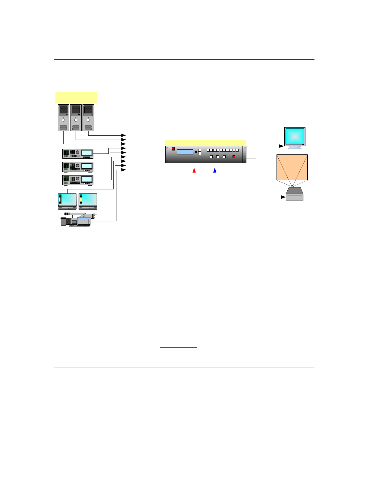
`зееЙЕнбобну=aб~Цк~г
The figure below illustrates a basic DCS-200 system.
Sample Source In pu t
Devices
Preview
Program
Inputs 1 - 6 (Analog)
Inputs 7 - 8 (DVI)
Input 9 (HD/SD SDI)
Figure 1-1. Block diagram, DCS-200 system
In the diagram:
Ethernet
DCS-200
Serial
• Up to nine sources can be connected to the DCS-200:
~ 6 x analog inputs (on HD-15 connectors), for a variety of YUV and
RGBHV sources, including CVBS and Y/C.
~ 2 x DVI inputs, for computer sources. These two DVI connectors also
support analog RGB inputs, and these inputs are universal, and accept
all types of sources — just like the six HD-15 connectors. (To connect
analog sources, use a customer-supplied DVI to HD-15 adapter.)
~ 1 x SD-SDI or HD-SDI input.
• The DCS-200 connects to a Preview monitor via analog or DVI.
• The DCS-200 connects to a projector (or other target device) via analog or DVI.
In Chapter 2, refer to the “Inputs Section” heading on page 22 for details on all inputs.
^ййдбЕ~нбзе=nмЙлнбзел
At Barco, we take pride in offering unique solutions to demanding technical problems. If
you have application questions, require further information or would like to discuss your
application requirements in more detail, please call (866) 469-8036. Our Customer
Support Engineers will be happy to supply you with the support you need. Refer to
Appendix C, “Contact Information
18 DCS-200 • User’s Guide
” on page 159 for details.
Page 19

OK==e~кЗп~кЙ=lкбЙен ~нбзе
få=qÜáë=`Ü~éíÉê
This chapter provides detailed diagrams of the DCS-200’s front and rear panels, along with
comprehensive explanations of each.
The following topics are discussed:
• DCS-200 Front Panel
• DCS-200 Rear Panel
DCS-200 • User’s Guide 19
Page 20
2. Hardware Orientation
DCS-200 Front Panel
a`pJOMM=cêçåí=m~åÉä
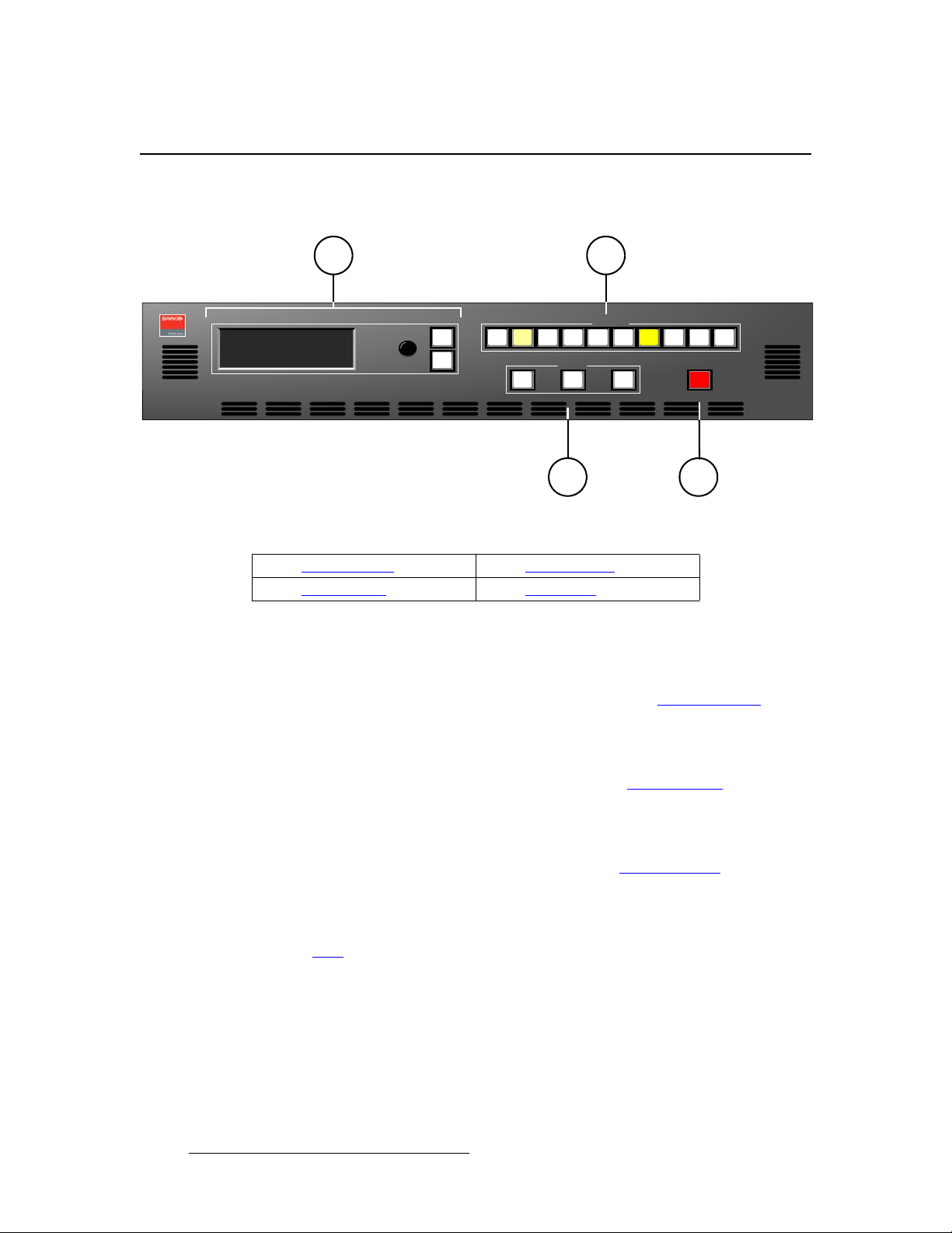
The figure below illustrates the DCS-200 front panel:
1
Adjust
SEL
ESC
PROGRAM:
NEXT:
1024x768 @59.94
RGB
SDI
NTSC (480i)
Figure 2-1. D CS-200 Fron t Panel
1) Display Section 3) Effects Section
2) Inputs Section 4) Take Button
Following are descriptions of each front panel section:
1) Display Section
The Display Section includes a four-line display, the ADJUST knob and two
“menu navigation” buttons: SEL and ESC. Refer to the “Display Section”
heading on page 21 for complete details.
2) Inputs Section
The Inputs Sect ion includes ten “source” buttons that enable you to select inputs,
key sources and a full screen LOGO. Refer to the “Inputs Section
page 22 for complete details.
3) Effects Section
The Effects Section provides three buttons that enable you to select the type of
effect that you want to perform next. Refer to the “Effects Section
page 23 for complete details.
4) Take Button
The red TAKE button initiates a transition to the selected source. Refer to the
“Take” section on page 24 for details.
2
Inputs
3 5 6 8 SDI 1 2 4 7 LOGO
Effects
KEY TAKE FRZ BLACK
3 4
DCS-200
” heading on
” heading on
20 DCS-200 • User’s Guide
Page 21
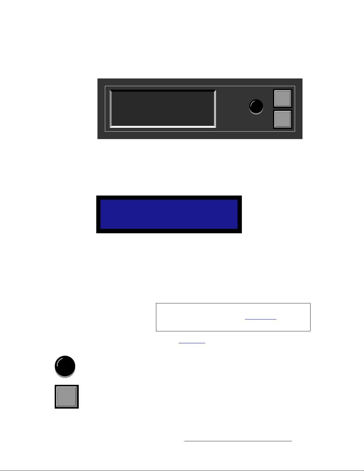
aблйд~у=pЙЕнбзе
The figure below illustrates the Display Section:
2. Hardware Orientation
DCS-200 Front Panel
PROGRAM:
1024x768 @59.94
NEXT:
Figure 2-2. Display Section with sample Status Menu
Descriptions of each button and control are provided below:
NTSC (480i)
RGB
SDI
Adjust
SEL
ESC
• The Menu Display is a 4-line x 20-character Vacuum Fluorescent Display (VFD)
that shows all DCS-200 menus and sub-menus. Brightness is adjustable. The
following illustration shows a typical DCS-200 menu.
SETUP MENU
> Trans Time 1.0
Output >>
Preview >>
Figure 2-3. Sample Setup Menu Display
For all setup menus, please note:
~ The top line names the current menu, in all capital letters.
~ The navigation cursor (>) in the left-hand column indicates the current
line on which action can be taken.
~ The double arrow (>>) indicates that a sub-menu is available.
Note
In Chapter 4, refer to the “Menu Tree
the system’s menu tree.
The Status Menu layout is different from the “setup” menu
display. In Chapter 4, refer to the “Statu s Menu
page 44 for details.
” section on page 38 for additional details on
” section on
• ADJUST — use the Adjust Knob to scroll through all system menus.
~ Turn the knob counter-clockwise (CCW) to scroll down.
~ Turn the knob clockwise (CW) to scroll up.
• SEL — press to enter the setup menu tree (from the Status Menu), to enter a
SEL
DCS-200 • User’s Guide 21
sub-menu, change a parameter, accept a parameter, or to answer “Yes” to certain
menu queries.
Page 22
2. Hardware Orientation
DCS-200 Front Panel
• ESC — press to exit a menu without making changes, cancel an operation, to
ESC
answer “No” to certain menu queries, and to return to the top Status Menu. Each
press takes you back up the menu tree by one level.
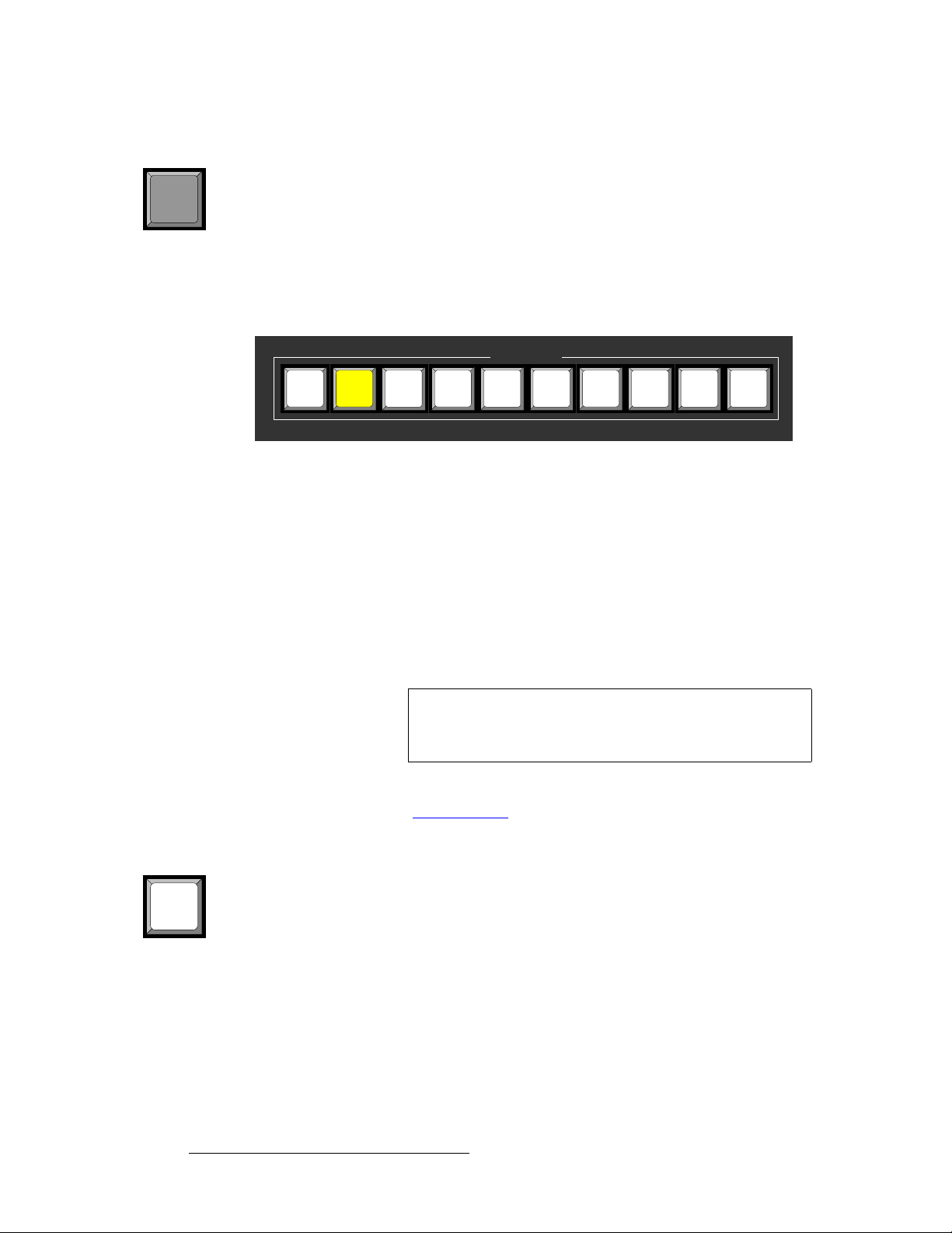
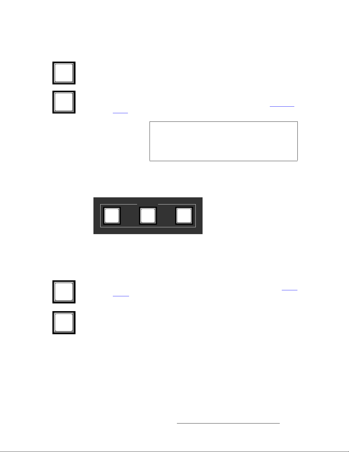
fеймнл=pЙЕнбзе
The figure below illustrates the Inputs Section:
Figure 2-4. Inputs Section
The buttons in the Inputs Section enable you to select the source that you want to
transition to Program. Each button corresponds to the similarly numbered input connector
on the rear panel. You can also select the full screen LOGO as the transition source.
There are three button states:
• Off — the input is not selected for a transition.
• Blinking — the input is “pending” for the next transition.
~ When a button is blinking fast, it is being acquired by the system.
~ When a button is blinking slow, it is ready to be transitioned to Program.
Inputs
3 5 6 8 SDI 1 2 4 7 LOGO
Note
If an input button is blinking slow, and the Status Menu
shows “Invalid Signal,” the system has attempted to acquire
the source, but has failed.
• Lit Solid — the input is on Program.
In Chapter 4, refer to the “Flip-flop Mode” section on page 85 for additional information
about button behavior when TAKE is pressed.
Following are descriptions of each “input” button in the section:
• Buttons 1 through 6 enable you to select physical inputs 1 through 6 (respectively)
1
from the rear panel HD-15 connectors.
• Buttons 7 and 8 enable you to select physical inputs 7 and 8 (respectively) from
the rear panel DVI-I connectors. Please note:
~ If a DVI signal is present, the DVI (digital) source is used from the DVI-I
connector’s digital pins.
~ If a DVI signal is not present, the selection defaults to the analog signals
that are on the DVI-I connector’s analog pins. Note that a customersupplied DVI to HD-15 adapter is required to connect to the analog pins.
22 DCS-200 • User’s Guide
Page 23
2. Hardware Orientation
DCS-200 Front Panel
SDI
LOGO
• The SDI button selects the SD-SDI or HD-SDI input source.
• The LOGO button selects the stored “full screen” LOGO image for the next
transition. If no image is stored, the transition will be to Black. Use the menu to
select one of three stored LOGOs for use. In Chapter 4, refer to the “Using the
LOGO” section on page 88 for details.
Note
If you press a button in the Inputs Section, it blinks to
indicate “pending.” If you do not want to pend a source
(which may be desirable in some situations), press the
blinking source button again. The button turns off, leaving
only the source on Program lit solid.
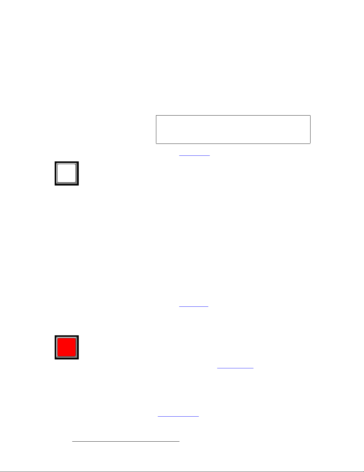
bССЙЕнл=pЙЕнбзе
The figure below illustrates the Effects Section:
Effects
KEY FRZ BLACK
FRZ
BLACK
Figure 2-5. Effects Section
The buttons in the Effects Section enable you to freeze the selected source on Program,
transition to black, and perform a key over the selected Program source.
Following are descriptions of each “effects” button:
• The FRZ button instantly freezes and unfreezes the current Program source.
When the source is frozen, the button is lit solid. In Chapter 4, refer to the “U
Freeze” section on page 92 for details.
sing
• The BLACK button enables you to transition to or from black. The button
performs one of two functions, depending on the way the button is defined in the
User Preferences Menu.
~ If “Black Auto Take” is Off:
• Press BLACK to pend a transition to or from black. The button
blinks to indicate “pending.”
• Press TAKE to perform the transition to or from black.
– If the transition is “to” black, the button lights solid
when black is on Program.
– If the transition is “from” black, the button turns off
when the selected source is fully on Program.
DCS-200 • User’s Guide 23
Page 24
2. Hardware Orientation
DCS-200 Front Panel
~ If “Black Auto Take” is On:
• Press BLACK to immediately transition to/from black.
– If the transition is “to” black, the button blinks fast
during the transition, then lights solid when black is on
Program.
– If the transition is “from” black, the button blinks fast
during the transition, then turns off when the selected
source is on Program.
Important
In Chapter 4, refer to the “Using Black
Regardless of the current Black Auto Take mode, if you
select (or pend) BLACK, the system will not transition to the
selected “next” source until black is fully on Program.
” section on page 93 for details.
• The KEY button enables you to key an un-scaled DVI source (input 7 or 8) over
KEY
the current Program source. The key’s clip, gain, opacity, and the selected key
source are adjusted using the menu. The button performs one of two functions,
depending on the way the button is defined in the User Preferences Menu.
~ If “Key Auto Take” is Off:
• Press KEY to pend a “key up” or “key down” transition. The
button blinks to indicate “pending.”
• Press TAKE to perform the key transition at the current rate.
– If the transition is a “key up,” the button lights solid
when the key is on.
– If the transition is a “key down,” the button
automatically turns off when the key is off.
~ If “Key Auto Take” is On:
• Press KEY to immediately perform the “key up” or “key down”
transition at the current rate.
– If the transition is a “key up,” the button blinks fast
during transition, then lights solid when the key is on.
– If the transition is a “key down,” the button blinks fast
during transition, then turns off when the key is off.
In Chapter 4, refer to the “Using Keys
” section on page 95 for details.
q~âÉ=
Press TAKE to mix the pending (blinking) source to Program, at the current transition rate.
TAKE
24 DCS-200 • User’s Guide
Using the Setup Menu, you can adjust the transition time from 0 to 12 seconds. If the
transition time is set to 0, the transition is a cut. Please note:
• Each time TAKE is pressed, the current source on Program and the pending
source flip-flop. In Chapter 4, refer to the “Flip-flop Mode
additional details.
” section on page 85 for
• The TAKE button is also used to transition a “key” up or down, when the “Key
Auto Take” function is On in the User Preferences Menu.
• The TAKE button is also used to transition to/from black, when the “Black Auto
Take” function is On in the User Preferen ce Menu.
In Chapter 4, refer to the “User Preference” section on page 70 for details on the User
Preference Menu.
Page 25
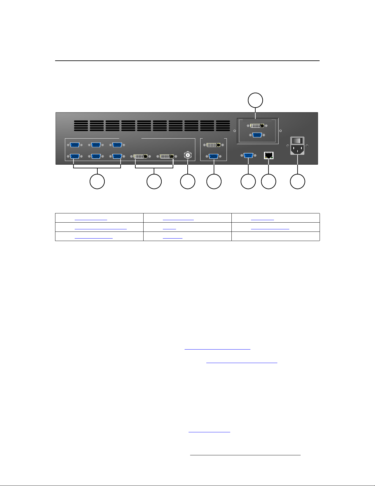
a`pJOMM=oÉ~ê=m~åÉä
The figure below illustrates the DCS-200 rear panel:
Input 1
Input 2
Input 3
Input 4
VIDEO INPUTS MAIN OUTPUTS
Input 5
Input 6 Input 7 Input 8
Figure 2-1. D CS-200 Rear Panel
2. Hardware Orientation
8
PREVIEW OUTPUTS
HD/SD SDI
3 71 2 4 5 6
SERIAL
DCS-200 Rear Panel
Model
DCS-200
100 - 240 VAC
50 – 60 Hz, 1.9A
ETHERNET
1) Analog Inputs 4) Main Outputs 7) AC Power
2) DVI and Analog Inputs 5) Serial 8) Preview Outputs
3) HD/SD SDI Input 6) Ethernet
Following are descriptions of each rear panel connector:
1) Analog Inputs
Six HD-15 connectors are provided for the system’s Analog inputs. Please note:
~ Each input provides 10-bits/color sampling at a maximum 165 MHz.
~ Each input supports 1:1 sampling up to 1600x1200@60 Hz. Sources
with native pixel rates greater than 165 MHz will be filtered and
undersampled at 165 Mhz. These include:
• 1920x1080p@60 (173.0 MHz)
• 1920x1200@60 (193.25 MHz)
• 2048x1080p@60 (183.75 MHz)
~ Composite and S-Video formats are supported.
In Chapter 3, refer to the “Format Connection Table” section on page 32 for a
table of analog inputs that you can connect using a customer-supplied breakout
cable. In Appendix A, refer to the “Analog 15-pin D Connector
” section on
page 118 for pinouts.
2) DVI and Analog Inputs
Two DVI-I connectors are provided for both digital and analog inputs.
~ Using the connector’s digital pins, an 8-bit digital input is supported.
~ Using the connector’s analog pins, RGBHV, analog composite, S-Video,
and YUV formats are supported. A customer-supplied breakout cable or
DVI to HD-15 adapter is required for these connections.
In Appendix A, refer to the “DVI-I Connector
” section on page 119 for pinouts.
DCS-200 • User’s Guide 25
Page 26

2. Hardware Orientation
DCS-200 Rear Panel
3) HD/SD SDI Input
One BNC connector is provided for the SD-SDI or HD-SDI input.
4) Main Outputs
Two connectors are provided for the DCS-200’s main program outputs. Both
outputs have the same resolution, and both can be used simultaneously.
~ One DVI-I connector is provided for the system’s digital program output.
There are no analog outputs on this connector. In Appendix A, refer to
the “DVI-I Connector
” section on page 119 for pinouts.
Note
The DVI-I connector allows you to use both DVI-D and DVI-I
cables as required.
~ One HD-15 connector is provided for the system’s analog output. In
Appendix A, refer to the “Analog 15-pin D Connector” section on
page 118 for pinouts
5) Serial
One DB-9 connector is provided for Serial communications with the DCS-200
system. The port is also used for diagnostics or command-line operations.
6) Ethernet
One RJ-45 connector is provided for 10/100BaseT Ethernet communications with
the DCS-200 system. The port is used for running the built-in web-based GUI, for
diagnostics, or for command-line operations via Telnet (using port 23).
S telnet 192.168.0.10 23
In Appendix A, refer to the “Ethernet Connector
pinouts.
7) AC Power
One AC Connector is provided for connecting DCS-200 to AC. The integral
switch turns the chassis on and off. In Appendix A, refer to the “Physical and
Electrical Specifications” section on page 117 for power details.
8) Preview Outputs
Two outputs are provided for connecting to the Preview monitor: an HD-15
connector for analog monitors and a DVI connector for digital displays.
” section on page 120 for
26 DCS-200 • User’s Guide
Page 27

PK==fåëí~ää~íáçå
få=qÜáë=`Ü~éíÉê
This chapter provides detailed instructions for installing the DCS-200 hardware. The
following topics are discussed:
• Safety Precautions
• Unpacking and Inspection
• Site Preparation
• Cable and Adapter Information
• Rack-Mount Installation
• Power Installation
• Signal Installation
• Format Connection Table
DCS-200 • User’s Guide 27
Page 28
3. Installation
Safety Precautions
p~СЙну=mкЙЕ~мнбзел=
For all DCS-200 installation procedures, observe the following important safety and
handling rules to avoid damage to yourself and the equipment:
• To protect users from electric shock, ensure that the power supplies for each unit
connect to earth via the ground wire provided in the AC power cord.
• The AC Socket-outlet should be installed near the equipment and be easily
accessible.
rей~ЕвбеЦ=~еЗ=fелйЙЕнбзе=
Inspect the shipping box for damage. If you find any damage, notify the shipping carrier
immediately for all claims adjustments. As you open the box, compare its contents against
the packing slip. If you find any shortages, contact your Barco sales representative.
Once you have removed all the components from their packaging and checked that all the
listed components are present, visually inspect each unit to ensure there was no damage
during shipping. If there is damage, notify the shipping carrier immediately for all claims
adjustments.
páíÉ=mêÉé~ê~íáçå=
The environment in which you install your DCS-200 should be clean, properly lit, free from
static, and have adequate power, ventilation, and space for all components.
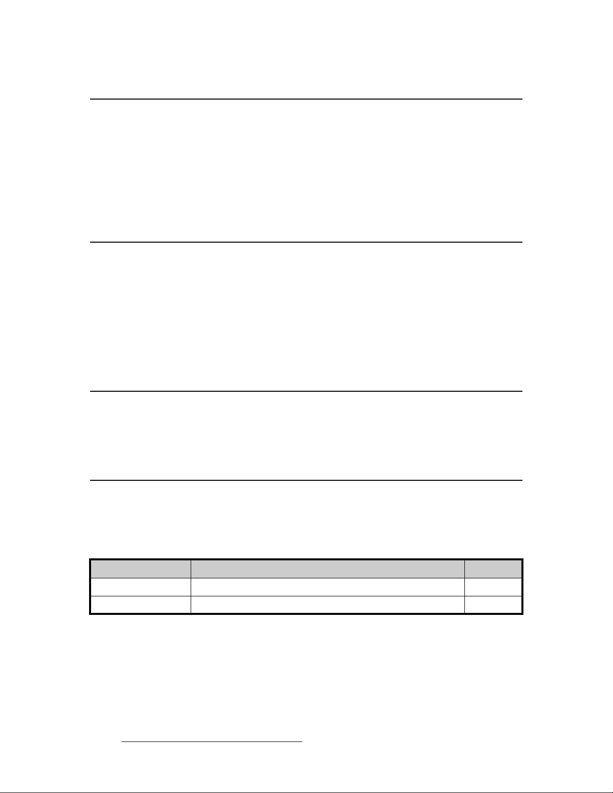
`~ДдЙ=~еЗ=^З~йнЙк=fеСзкг~нбзе
The table below provides information regarding supplied cables and adapters:
Table 3-1. DCS-200 Cables and Adapters
Cable / Adapter Description Quantity
AC Power Cord 7 foot, 10A (US Power Cord) 1
AC Power Cord 7 foot, 10A (European Power Cord) 1
28 DCS-200 • User’s Guide
Page 29

o~ÅâJjçìåí=fåëí~ää~íáçå
DCS-200 units are designed to be rack mounted and are supplied with front rack-mount
hardware. Please note the following important points:
• When rack mounting the unit, remember that the maximum ambient operating
temperature for the unit is 40 degrees C.
• Leave sufficient front and rear space to ensure that the airflow through the fan and
vent holes is not restricted.
• When installing equipment into a rack, distribute the units evenly to prevent
hazardous conditions that may be created by uneven weight distribution.
• Connect the unit only to a properl y rate d sup pl y c ircuit.
• Reliable grounding (earthing) of rack-mounted equipment should be maintained.
• Rack mount the unit from the front rack ears using four rack screws (not supplied).
Rack threads may be metric or otherwise — depending upon the rack type.
• Install the lower of the two mounting holes first.
3. Installation
Rack-Mount Installation
mçïÉê=fåëí~ää~íáçå
Use the following steps to install power to the DCS-200:
1. Connect an AC power cord to the AC Power Connector on the rear of the
DCS-200, and then to an AC outlet.
2. Connect AC Power cords (or AC adapters) to all peripheral equipment, such as
video sources, VTRs and PCs. Please note:
~ Connect each unit only to a properly rated supply circuit.
~ Reliable grounding of rack-mounted equipment should be maintained.
DCS-200 • User’s Guide 29
Page 30
3. Installation
Power Installation
mзпЙк=`зкЗLiбеЙ=sздн~ЦЙ=pЙдЙЕнбзе
DCS-200 is rated to operate with the following specifications:
• Input Power: 100-240 VAC, 50-60 Hz
• Power Consumption: 240 watts maximum
DCS-200 performs line voltage selection automatically, and no user controls are required.
The AC power cords must be accessible so that they can be removed during field servicing.
Warning
Figure 3-1. Tandem Prong-type Plug
Avertissement
When the DCS-200 is used in the 230-volt mode, a UL listed
line cord rated for 250 volts at 15 amps must be used and
must conform to IEC-227 and IEC-245 standards. This cord
will be fitted with a tandem prong-type plug.
The rear panel ON/OFF switch does not disconnect the unit
from input AC power. To facilitate disconnection of AC
power, the power cord must be connected to an accessible
outlet near the unit.
Building Branch Circuit Protection: For 115 V use 20 A, for
230 V use 8 A.
La choix de la ligne de voltage se réalise automatiquement
par le DCS-200 Transformateur Graphique. On n'a pas
besoin du controller usager pour la choix de la ligne de
voltage.
Warnung
30 DCS-200 • User’s Guide
Das DCS-200 gerät mu beim Anschlu an 240V ~ mit einer
vom VDE auf 250V/10A geprüften Netzleitung mit einem
Schukostecker ausgestattet sein.
Page 31

páÖå~ä=fåëí~ää~íáçå
The figure below illustrates a sample DCS-200 system. Use this figure for reference during
the signal installation process.
Sample Source Input
Devices
3. Installation
Signal Installation
Program
Preview
Ethernet
DCS-200
Serial
Inputs 1 - 6 (Analog)
Inputs 7 - 8 (DVI)
Input 9 (HD/SD SDI)
Figure 3-2. DCS-200 System Diagram (sample)
Use the following steps to install signals to/from the DCS-200:
1. Input connections — any combination of inputs can be connected.
a. As required, connect analog RGBHV sources to Inputs 1 through 6.
Refer to the “Format Connection Table” section on page 32 for a table
of analog input combinations.
b. As required, connect DVI sources to Inputs 7 and 8 (using the
connector’s digital pins).
c. As required, connect analog sources to Inputs 7 and 8 (using the
connector’s analog pins). A customer-supplied breakout cable or DVI to
HD-15 adapter is required for this connection.
d. As required, connect an HD-SDI or SD-SDI source to Input 9.
2. Output connections — up to three outputs can be connected:
a. If you are connecting the DCS-200 to a digital projector (for example) or
other target device, connect the DVI Output to the projector’s DVI input.
b. If you are connecting the DCS-200 to an analog projector (for example)
or other target device, connect the Analog (HD-15) Output to the
projector’s analog input.
c. If you are connecting the DCS-200 to a Preview monitor, connect the
Preview DVI or Analog (HD-15) Output to the monitor.
DVI
Program
Analog
DCS-200 • User’s Guide 31
Page 32

3. Installation
Format Connection Table
3. GUI connection — to configure your system to run from the built-in web-based
4. Communications connection — two methods are available for remote control:
This completes system signal installation. Please continue with system setup, menu
orientation and operations, as outlined in Chapter 4, “Operation” on page 33.
GUI, perform the following steps:
®
a. Ensure that your PC (or laptop) uses Windows
2000 or XP.
b. Ensure that your PC (or laptop) has a web browser installed, such as
Windows Internet Explorer
®
or Mozilla Firefox®.
c. Ensure that your PC is using Java Version 6 or later.
d. Connect the DCS-200’s Ethernet port to a Switch.
e. Connect the Switch to your PC (or laptop).
This completes the required “physical” connections. Refer to Chapter 5, “GUI
Operations” on page 103 for installation and operating instructions.
a. Connect the DCS-200’s Ethernet port to an Ethernet switch, and
connect the switch to the other Ethernet devices in your local system.
This enables you to communicate with the DCS-200 via Telnet. In
Appendix B, refer to the “Communicating with DCS-200” section on
page 127 for details.
b. For a serial remote connection, connect the DCS-200’s Serial port to the
serial port of a laptop or a PC. In Appendix B , refer to the
“Communicating with DCS-200
” section on page 12 7 for details
cзкг~н=`зееЙЕнбзе=q~ДдЙ
Use the following table to connect various source formats to the DCS-200, using the analog
HD-15 connectors (on Inputs 1 through 6). Please note:
• RGB format — typical devices: Computers
• YUV or YP
Using a customer supplied VGA to 5 x BNC breakout cable, multiple input combinations
are possible. Cells with checks denote the connections required for the indicated format.
Table 3-2. Analog Input Combinations using Breakout Cable
Breakout Cable
Wire Color
R
G
B
H Sync
V Sync
Composite
Video
33 (Lum)
Please contact Barco Technical Support for information on obtaining breakout cables. In
Appendix C, refer to the “Contact Information
(Betacam) format — typical devices: DVD player, Betacam deck
bPr
S-Video
(Y/C)
3 (Chrom)
YUV
(YP
bPr
3 (P
) 3
r
3 (Lum)
3 (P
)
b
Sync on Green
)
RGB
RGB
Comp Sync
RGB
Separate H V
33
333
333
33
3
” section on page 160 for details.
32 DCS-200 • User’s Guide
Page 33

QK==léÉê~íáçå
få=qÜáë=`Ü~éíÉê
This chapter provides comprehensive menu descriptions and detailed operating
instructions for the DCS-200. The following to pi cs ar e di scu sse d :
• Control Overview
• Power-Up Initialization
• Button States
• Quick Setup and Operations
• Menu Tree
• Using the Menu System
• Quick Function Reference
• Status Menu
• Using the Setup Menu
• Using Inputs
• Using the LOGO
• Using Freeze
• Using Black
• Using Keys
• Understanding Front-Pane l Lo ck o ut
DCS-200 • User’s Guide 33
Page 34

4. Operation
Control Overview
`зенкзд=lоЙкобЙп
There are several ways to control the DCS-200:
• The front panel is ideal for all basic operations. Available controls include the
Display Section and the buttons in the Inputs Section and the Effects Section.
• The built-in web-based GUI is ideal for intuitive point-and-click operations. Refer
to Chapter 5, “GUI Operations” on page 103 for additional details.
• The DCS-200 can also be controlled remotely via Ethernet or Serial
communications. See Appendix B “Remote Control” on page 127 for additional
details.
mçïÉêJré=fåáíá~äáò~íáçå
After connecting power to the DCS-200, locate the power switch on the back of the chassis,
and turn power ON. While the system is initializing, the following messages are displayed:
DCS-200
Barco
Initializing...
Figure 4-1. System Initialization Message 1 (sample)
Program Loading
please wait...
Figure 4-2. System Initialization Message 2 (sample)
Transferring to
main program.
Figure 4-3. System Initialization Message 3 (sample)
34 DCS-200 • User’s Guide
Page 35

4. Operation
Button States
DCS-200
Barco
Version 1.0
Initializing...
Figure 4-4. System Initialization Message 4 (sample)
The “version” line in the above menu shows the software version that is currently installed.
This version number changes as software upgrades are released.
When you first start up a DCS-200 that has stored logos, a message like the one in the
following illustration appears during initialization:
LOGO1 loading...
5%
After system initialization is complete, the Status Menu appears.
_мннзе=pн~нЙл
Remember that there are three states for the buttons in the Inputs Section:
Remember also that when you press TAKE, the DCS-200 automatically flip-flops the
current source on Program with the “pending” source. Refer to the “Flip-flop Mode”
section on page 85 for additional information.
Figure 4-5. LOGO Initialization Message (sample)
• Off — the input is not selected for a transition.
• Blinking — the blinking status depends on the type of button:
~ For an input button:
• When blinking fast, the input is being acquired by the system.
• When blinking slow, the input is ready to be transitioned to
Program.
~ For an effect button (BLACK, KEY):
• When blinking fast, the button’s “auto take” mode is ON, and
the effect is currently transitioning on or off.
• When blinking slow, the button’s “auto take” mode is OFF, and
the effect is pending for the next transition.
• Lit Solid — the input or the effect is on Program.
DCS-200 • User’s Guide 35
Page 36

4. Operation
Quick Setup and Operations
nмбЕв=pЙнмй=~еЗ=lйЙк~нбзел
For the optimum speed in setting up and operating your system, use the following steps.
For reference, links are provided to the appropriate sections in this guide.
1. Connect power — Ensure that power is properly connected to the DCS-200.
(Chapter 3, “Power Installation
2. Connect inputs — Connect all input sources to the DCS-200. (Chapter 3,
“Signal Installation,” page31.
3. Connect outputs — Connect the output(s) of the DCS-200 to your projector(s) or
other target devices. (Chapter 3, “Signal Installatio n ,” page 31.
4. Turn on power — Turn on power to the DCS-200, your projector(s), and to all
peripheral equipment. (This chapter, “Power-Up Initialization,” page 34.)
5. Factory reset — If you are using the DCS-200 for the first time, or if you are using
a DCS-200 that has just returned from another event, perform a full factory reset
to restore system configurations. (This chapter, “Factory Reset
6. Launch GUI — (Optional) If you want to run the system from the web-based GUI,
ensure that Ethernet is connected between your PC and the DCS-200, then
launch the GUI. (Chapter 5, “GUI Operations,” page 103.)
7. Set output format — Set the desired output resolution and frame rate. (This
chapter, “Output Format,” page48.)
8. Enable test pattern — Tur n on th e de si re d te st pattern, verify that you have an
image, and make the necessary adjustments. When complete, turn off the test
pattern. (This chapter, “Test Pattern,” page48.)
9. Save output configuration — After completing all output adjustments, save the
output configuration. (This chapter, “Save Output Config,” page 49.)
10. Select and adjust inputs — As required, select an input, and perform the
necessary adjustments. (This chapter, “Input Menu,” page 53.)
11. Save input configuration — After completing all adjustments for an input, save
the input configuration. (This chapter, “Save Config,” page 64.)
12. Repeat for each input — repeat steps 9 and 10 for each input that you have
connected to the DCS-200.
13. Adjust key source — As required, select the desired key source, and adjust its
clip, gain and opacity. (This chapter, “Using Keys
14. Adjust system parameters — As required, adjust all desired system parameters
such as transition time, display brightness, and all user preferences. (This
chapter, “Trans Time
15. Save system configuration — After completing all system adjustments, save the
system configuration. (This chapter, “Save System State,” page 81.)
16. (Optional) Remote Control — To control th e D CS- 200 remotely, ensure that
Ethernet or Serial communications are connected, then establish communications
and issue commands. (Appendix B, “Remote Control
,” page 29.)
,” page 82.)
,” page 95.)
,” page 47 and “System Menu,” page 73.)
,” page 127.)
36 DCS-200 • User’s Guide
Page 37

4. Operation
Quick Setup and Operations
17. Ready to roll — With all output, input and system configurations saved, press the
desired input button, and press TAKE.
Note
For advanced system operations, specific system “tweaks”
and operating descriptions on every feature, please start with
the “Quick Function Reference
select the function that you wish to perform.
” section on page 41, and
DCS-200 • User’s Guide 37
Page 38

4. Operation
Menu Tree
jÉåì=qêÉÉ
Status Menu
Setup Menu
Trans Time
The figure below illustrates the entire DCS-200 menu tree. Please use this diagram for
reference as you learn how to operate the system.
Output
Output Format
Test Pa tte rn
Sync Setup
Gamma
Save Config
Mode
Type
Raster Box
Analog Sync
DVI Sync
Outpu t S rc
Outpu t F o rm a t
Test P a tte rn
Sync Setup
Save
Input System Tech Support
Inpu t F o rmat
Adjust On
Type
Colorspace
Background
Timing Adjust
Image Adjust
Contrast
Brightness
Color B alance
Processing
Reset Config
Save Config
Delete C o n fig
Recall Config
Auto C o n fig *
Sampling
Phase A
Phase B
H Total
H Position
H Active
V Total
V Position
V Active
Auto C o n fig *
H Size
V Size
H Pan
V Pan
Aspec t R a tio
Reset All
Red Contrast
Red Bright
Grn Contrast
Grn Bright
Blue Contrast
Blue Bright
Reset All
Saturation
Hue
Reset All
Sync Sel
Pulldown Cmp
Sync Slice
Key SetupPreview
Input
Clip
Gain
Opacity
H Offse t
V Offse t
Use Timing Adjust for analog
input sources except NTSC
and PAL.
Use Image Adjust for DVI,
SDI, NTSC and PA L input
sources.
RGB
SDI
Comp
LOG O S e tu p
Selection
Status
Save LOGO
Delete L O GO
YPbPr
S-Video
User Preference
In Auto Acq uire
Auto Input C fg
Auto Input S a ve
Auto Take
Black Auto Take
Key Auto Take
Menu Context
VFD Brightness
Ethernet
DHCP
Config Network
Set Sta tic IP
Set Ne tmask
Set G a te way
IP
M
Serial Setup
Baud
Parameters
Handshaking
Reset
EDID Setup
Input
EDID Format
Type
DVI Cable EQ
Input
Equalization
Set to D e fa u lt
Set to M a x im u m
Set to Minimum
Executive Mode
File Association
Input 1
Input 2
Input 3
Input 4
Input 5
Input 6
Input 7
Input 8
SDI
Temperature
Temp °F
Temp °C
Diagnostics
Start Tests
Save State
Version
Phone
Factory Reset
Figure 4-6. D CS-200 Menu Tree
* The “Auto Config” selection is only available when an analog input is chosen.
38 DCS-200 • User’s Guide
Page 39

rлбеЦ=нЬЙ=jЙем=pулнЙг
This section lists the rules and conventions for using DCS-200’s menu system. For
reference, the figure below illustrates the Setup Menu:
SETUP MENU
> Trans Time 1.0
Output >>
Preview >>
Figure 4-7. Setup Menu (sample)
For all setup menus, please note the following important menu rules and conventions:
• The top line names the current menu, in all capital letters.
• Subsequent lines typically display two fields:
~ For a listed function, the left-hand field names the function, and the
right-hand field is the function’s current parameter or value.
~ For a listed sub-menu, the left-hand field names the sub-menu that you
can access, and the right-hand field displays the double arrow (>>),
indicating that a sub-menu is available.
• The “navigation” cursor (>) in the left-hand column indicates the current line on
which action can be taken. This arrow “scrolls” as you rotate the knob.
• Scrolling:
~ Turn the ADJUST knob counter-clockwise (CCW) to scroll down.
~ Turn the ADJUST knob clockwise (CW) to scroll up.
• To enter a sub-menu, scroll to the desired line and press SEL.
4. Operation
Using the Menu System
Note
Throughout this chapter, the term “select” is used as an
abbreviation for “scroll to a menu line and press SEL.”
S Select the Input field to...
• To change a parameter, scroll to the desired line and press SEL. The cursor
changes to the “edit” cursor (
#). Use the ADJUST knob to modify the value:
~ Turn the ADJUST knob CW to increase a value.
~ Turn the ADJUST knob CCW to decrease a value.
• To accept a p ara mete r or val ue, press SEL. The edit cursor changes back to the
navigation cursor.
Note
You must press SEL to activate a DCS-200 function.
• In the “edit” mode, to exit (or cancel) without changing the origina l parameter,
press
ESC.
• To navigate back up the menu structure, press ESC. Each press takes you back
up the menu tree by one level.
DCS-200 • User’s Guide 39
Page 40

4. Operation
Using the Menu System
• The SEL button is also used to answer “Yes” to certain menu queries. The ESC
button is also used to answer “No” to certain menu queries.
Note
The display itself is four lines high, and the ADJUST knob is
used to scroll through the various lines. Throughout this
chapter, entire menus will be shown for clarity — rather th an a
series of four-line sections.
• If a value is displayed between brackets, (e.g., [SMPTE]) this indicates that the
value can not be changed.
40 DCS-200 • User’s Guide
Page 41

4. Operation
Quick Function Reference
nмбЕв=cмеЕнбзе=oЙСЙкЙеЕЙ
Use the following table to quickly access the proper section for a specific function. Both
hyperlinks and page numbers are provided.
Table 4-1. DCS-200 Quick Function Reference Table
How to: Use the Following Section: Page
Adjust background color Background 57
Adjust gamma Gamma
Adjust image brightness Brightness
Adjust image color balance Color Balance
Adjust image contrast Contrast
Adjust input processing Processing
Adjust input timing Timing Adjust
Adjust the image Image Adjust
Adjust transition time Trans Time
Associate configuration files to inputs F
Check software version Tech Support
Contact Tech Support Tech Support
Delete input configuration Delete Config
Display a test pattern Test Pattern
Display the raster box Test Pattern
Identify button states Button States
Learn the menu tree Menu Tree
Lock out the front panel completely Full Lockout Mode
ile Association Menu 79
49
61
62
61
63
57
60
47
82
82
65
48
48
35
38
101
Lock out the front panel, except inputs Executive Lockout Mode
Perform a key Performing a Key
Perform factory reset Factory Reset
Perform key combinations Key Transition Combinations
Perform quick setup and operations Quick Setup and Operations
Perform system diagnostics Diagnostics
Power up the system Power-Up Initialization
Reset input configuration Reset Config
Reset system Factory Reset
Save input configuration Save Config
101
96
82
97
36
81
34
64
82
64
DCS-200 • User’s Guide 41
Page 42

4. Operation
Quick Function Reference
Table 4-1. DCS-200 Quick Function Reference Table (Continued)
How to: Use the Following Section: Page
Save output configuration Save Output Config 49
Save system state Save System State
Select inputs Input Selection Rules
Set Auto Input Config mode Auto Input Config
Set Auto Input Save mode Auto Input Save
Set Auto Take mode Auto Take
Set Black Auto Take mode Black Auto Take
Set color input space Colorspace
Set DVI cable equalization DVI Cable Equalization
Set Ethernet parameters Ethernet
Set In Auto Acquire mode In Auto Acquire
Set input format Input Format
Set input type Type
Set Key Auto Take mode Key Auto Take
Set Menu Context mode Menu Context
Set or change multiple input configurations F
Set or change a single input configuration Recall Config
Set output format Output Format
ile Association Menu 79
81
84
71
72
72
72
56
79
74
70
55
56
72
73
66
48
Set Preview or Program mode Adjust On
Set Serial port parameters Serial Setup
Set up EDID EDID Setup
Set up Key Key Setup Menu
Set up LOGO LOGO Setup Menu
Set up sync Sync Setup
Set user preferences U
Set VFD brightness VFD Brightness
Understand auto acquire Understanding Auto Acquire
Use Black Using Black
Use Freeze U
Use HDCP Using HDCP
Use inputs Using Inputs
Use Keys Using Keys
Use the Input Menu Input Menu
ser Preference 70
sing Freeze 92
55
76
77
67
69
49
73
86
93
86
84
95
53
42 DCS-200 • User’s Guide
Page 43

4. Operation
Quick Function Reference
Table 4-1. DCS-200 Quick Function Reference Table (Continued)
How to: Use the Following Section: Page
Use the Key Setup Menu Key Setup Menu 67
Use the LOGO Using the LOGO
Use the LOGO Setup Menu LOGO Setup Menu
Use the menu system U
Use the Output Menu Output Menu
Use the Preview Menu P
Use the Setup Menu Using the Setup Menu
Use the Status Menu Status Menu
Use the System Menu System Menu
Use the User Preference Menu U
View chassis temperature Temperature
View LOGO status LOGO Setup Menu
View software version Tech Support
View Tech Support number Tech Support
sing the Menu System 39
review Menu 50
ser Preference 70
88
69
47
46
44
73
80
69
82
82
DCS-200 • User’s Guide 43
Page 44

4. Operation
Status Menu
pí~íìë=jÉåì
The Status Menu is the system’s top level display, which appears by default after the
DCS-200 boots up.
The figure below illustrates a sample Status M enu:
• To return to the Status Menu from any point within the Setup Menu, press ESC
repeatedly.
• To display the Setup Menu from the Status M enu, press SEL.
PROGRAM: RGB
1024x768@59.94
NEXT: SDI
NTSC (480i)
Figure 4-8. Status Menu (sample)
The Status Menu provides information about the current input on Program (the button that
is lit solid), and the input that is next to be transitioned to Program (the button that is
blinking). The Status Menu always updates as “current” and “next” sources change.
Please note:
— Program Input Type
— Program Input Format
— Next Input Type
— Next Input Format
• If Menu Context is ON (in the User Preference Menu), selecting a different input
for the “next” transition automatically displays the Input Menu. This menu always
reflects the source currently on Program. To return to the Status Menu, press
ESC repeatedly.
• If Menu Context is OFF, the Status Menu remains on display when you select a
different input.
In the Status Menu, the variable fields are as follows:
• Program Input Type — Specifies the type of input signal currently on Program.
• Program Input Format — Indicates the current input video format, in the form:
Hact x Vact @ Vr Hz
S 1280x1024@60 Hz
If the currently selected input does not have a valid input signal, the Input Format
field displays Invalid Signal.
Please note the following conventions for displaying resolutions:
Table 4-2. Status Menu Conventions
Convention Description
Hact x Vact @ Vr No symbols. The current format is an exact match from the table. The
*Hact x Vact @ Vr* Asterisks. The format has been “best guessed.”
[Hact x Vact @ Vr] Brackets. The exact table match has been saved.
[*Hact x Vact @ Vr*] Brackets plus Asterisks. The best guessed format has been saved.
44 DCS-200 • User’s Guide
format has not been “best guessed” or saved.
Page 45

4. Operation
Status Menu
• Next Input Type — indicates the next input type on Program, and (if applicable),
the system’s HDCP status. The following labels can appear, depending on the
output and HDCP implementation:
~ HDCP
~ HDCP Violation
Important
If the label “HDCP Violation” appears, an HDCP source is
selected, but a non-HDCP compliant device (e.g., an HDCP
repeater) has been detected. Video output is disabled.
• Next Input Format — Indicates the input formats on Program, in the form:
Hact x Vact @ Vr Hz
S 1400x1050@59.94 Hz
DCS-200 • User’s Guide 45
Page 46

4. Operation
Using the Setup Menu
rëáåÖ=íÜÉ=pÉíìé=jÉåì
After DCS-200 initialization is complete, the Status Menu appears. This is the system’s
top-level menu. Refer to the “Status Menu
To display the Setup Menu from the Status Menu, press SEL.
” section on page 44 for details.
Note
The figure below illustrates the Setup Menu:
When you make changes to input, output and system
parameters, your “configuration” information can be stored in
non-volatile memory — provided that you perform a “Save
Config” operation. In this way, your settings will be recalled
automatically each time the unit is turned on. Note that if the
“Auto Input Save” function is enabled in the User
Preferences Menu, the system automatically saves inputs.
SETUP MENU
> Trans Time 1.0
Output >>
Preview >>
Input >>
Key Setup >>
Logo Setup >>
User Preference >>
System >>
Tech Support >>
Factory Reset
Figure 4-9. Setup Menu (sample)
Following are descriptions of each Setup Menu function:
• Tran s Time
• Output Menu
• Preview Menu
• Input Menu
• Key Setup Menu
• LOGO Setup Menu
• User Preference
• System Menu
• Tech Support
• Factory Reset
46 DCS-200 • User’s Guide
Page 47

4. Operation
Using the Setup Menu
qê~åë=qáãÉ
From the Setup Menu, select Trans T ime to change the current transition rate that is used when you mix between inputs, when you transition to/from keys, and when you transition to/from black.
Following are two illustrations of the transition interval:
• Standa rd Mix — When transitioning between inputs and the LOGO, or
transitioning to/from black, the DCS-200 functions as a seamless switcher. The
transition interval is defined as the total time required to mix to the new source, or
fade to/from black.
Video
Input 1 Input 2
Black
Figure 4-10. Transition interval diagram — mix between sources
Mix
Transition Time
• Mix plus Digital Key — When transitioning to/from a digital key source, the
definition is the same as a standard mix — the total time required to fade to the
new source, plus or minus a key.
Video
Black
Transition values are listed below:
Digital Key Source
Input 1 Input 2
Figure 4-11. Transition interval diagram — mix between sources and a digital key
Note that transition times are specified for switching applications with Auto
Acquire turned OFF. When Auto Acquire is ON, the transition time is greater,
due to the additional time required to analyze the input video timing.
Mix
Transition Time
• Adjustment range: 0.0 - 12.0 seconds (0.0 is a cut)
• Default: 1.0 seconds
lмнймн=jЙем
From the Setup Menu, select Output to display the Output Menu.
OUTPUT
> 1024x768 @59.94
Test Pattern >>
Sync Setup >>
Gamma 1.3
Save Config
Figure 4-12. Output Menu (sample)
DCS-200 • User’s Guide 47
Page 48

4. Operation
Using the Setup Menu
Following are descriptions of each Output Menu function:
lмнймн=cзкг~н
From the Output Menu, select the top Output Format line to view or change the current
output format. This line indicates the format in the following form:
The output format for the DCS-200 can be set to any of the progressive outputs in the
format table. In Appendix A, refer to the “Format Table” section on page 122 for details.
• Output Format
• Test Pattern
• Sync Setup
• Gamma
• Save Output Config
Hact x Vact @ Vr Hz
Note
The output format is not updated until SEL is pressed.
qЙлн=m~ннЙке
From the Output Menu, select Test Pattern to display the Test Patterns Menu:
TEST PATTERNS
> Mode ON
Type Burst
Raster Box OFF
Figure 4-13. Test Patterns Menu (sample)
The following functions are available on the menu:
• Mode — This function enables or disables the test pattern generator.
• Type — This function enables you to select a test pattern. Available choices are:
~ H Ramp
~ V Ramp
~ 100% Col Bars
~ 75% Col bars
~ 16 x 16 Grid
~ 32 x 32 Grid
~ Burst
~ Gray Steps 1
~ Gray Steps 2
~ Red
~ Green
~ Blue
~ White
~ Black
~ 50% Gray
48 DCS-200 • User’s Guide
Page 49

4. Operation
Using the Setup Menu
• Raster Box — This function enables or disables the raster box on the output.
~ When turned ON, the system displays a one-pixel border around the
active output area. Note that the raster box includes gaps that enable
you to precisely align the input video to fill the output raster.
~ When turned OFF, the output is clean, without the border.
póåÅ=pÉíìé
From the Output Menu, select Sync Setup to display the Output Sync Select Menu:
OUTPUT SYNC SELECT
> Analog Sync -H-V
DVI Sync +H+V
Figure 4-14. Output Sync Select Menu (sample)
The Output Sync Select Menu enables you to independently adjust the output sync
polarity of the Analog and DVI outputs. The following functions are available:
• Analog Sync — This field sets the analog output sync polarity.
~ Values: CSync, -H-V, -H+V, +H-V, +H+V
~ Default: -H-V
• DVI Sync — This field sets the DVI output sync polarity.
~ Values: -H-V, -H+V, +H-V, +H+V
~ Default: +H+V
d~ãã~
From the Output Menu, select Gamma to specify the output Gamma.
• Adjustment range: 1.0 to 3.0, in steps of 0.1
• Default: 1.0
p~оЙ=lмнймн=`зеСбЦ
From the Output Menu, select Save Config to save the current output configuration. A
message is briefly shown, after which the system returns to the Output Menu.
Saving Output Config
Figure 4-15. Saving Output Configuration Message
DCS-200 • User’s Guide 49
Page 50

4. Operation
Using the Setup Menu
Please note the following important points regarding the output configuration file:
• When you perform the Save Config function, all configuration parameters from
the Output Menu are saved in non-volatile memory. If you do not perform the
function, output data will not be restored upon the next system power up.
• If you make a change in the Output Menu, and attempt to exit the menu (by
pressing ESC) without saving changes, the system displays the following prompt:
Save Output Cfg?
<SEL> = Yes
<ESC> = No
Figure 4-16. Save Output Configuration Prompt
~ Select Yes (SEL) to save changes.
~ Select No (ESC) to continue operation without saving the changes.
mкЙобЙп=jЙем
From the Setup Menu, select Preview to configure the DCS-200’s Preview output. The
Preview output allows you to view, resize, and otherwise adjust the input source before
taking it to Program. You can preview each of the input sources (1 through 8, SDI and
LOGO). The input source is scaled to the selectable progressive resolution and output on
the DVI Digital and HD-15 analog VGA connectors.
The following illustration shows the Preview Menu:
PREVIEW
Output Src Program
1024x768@59.94
Test Patterns >>
Sync Setup >>
Save
Figure 4-17. Preview Menu (sample)
Note
After you view and adjust a source on the preview monitor,
and press TAKE to bring it to Program, the preview and
Program images exchange positions, or “flip-flop,” as
described in the “Flip-flop Mode
is a slight delay in the image exchange between the preview
output and the Program output. The preview image appears
slightly after the Program image.
” section on page 85. There
50 DCS-200 • User’s Guide
Page 51

4. Operation
Using the Setup Menu
The following sections provide detailed information about Preview Menu functions:
• Output Src • Preview Sync
• Output Format (Preview) • Save (Preview)
•T est Patterns (Preview)
lмнймн=pкЕ
In the Preview Menu, choose Output Src to select the source to be displayed on the
preview monitor. The source can be either Preview or Program.
• Choose Preview to display on the preview monitor the “pending” source.
• Choose Program to display on the preview monitor the same source that is on
Program.
Important
In Preview mode, when you press KEY to “pend” th e key
transition, you will not see the key overlay on the preview
monitor. If you then press TAKE, the input and key appear
on Program.
To see the key on the preview monitor, you can route the
source from Program to preview using the Output Src
selection of the Preview Menu. This selection places a copy
of the Program image on the preview monitor, including the
key. For more information about keys, see the “Using Keys
section on page 95.
lмнймн=cзкг~н=EmкЙобЙпF
In the Preview Menu, the [output_format] field displays the format of the output, in the
following form:
Hact x Vact @ Vr Hz
S 1024x768@59.94
The output format for the DCS-200 can be set to any of the progressive outputs in the
format table. In Appendix A, refer to the “Format Table” section on page 122 for details.
Note
To make pixel-for-pixel adjustments, set the Preview and Program resolutions to be the
same, as shown in the following illustration:
The output format is not updated until you press SEL.
”
Figure 4-18. Matching Preview and Program Resolutions
If you do not need to make pixel-pe rfect adjustment s to the Preview image, the resolutions
of the Preview and Program outputs do not need to be the same, as shown in the following
DCS-200 • User’s Guide 51
Page 52

4. Operation
Using the Setup Menu
illustration:
qЙлн=m~ннЙкел=EmкЙобЙпF
In the Preview Menu, the Test Patterns submenu provides the following options:
Figure 4-19. Different Preview and Program Resolutions
• Mode enables or disables the test pattern generator. The values are ON and OFF.
• Type provides a list of the available test patterns. The choices are:
~ H Ramp
~ V Ramp
~ 100% Col Bars
~ 75% Col bars
~ 16 x 16 Grid
~ 32 x 32 Grid
~ Burst
~ Gray Steps 1
~ Gray Steps 2
~ Red
~ Green
~ Blue
~ White
~ Black
~ 50% Gray
• Raster Box — This function enables or disables the raster box on the Preview
output.
~ When turned ON, the system displays a one-pixel border around the
active output area. Note that the raster box includes gaps that enable
you to precisely align the input video to fill the output raster.
~ When turned OFF, the output is clean, without the border.
mкЙобЙп=pуеЕ=
From the Preview Menu, select Sync Setup to independently adjust the output sync
polarity of the analog and DVI outputs of the Preview. The Preview Sync Menu looks like
the one in the following illustration.
PREVIEW SYNC
Analog Sync -H-V
DVI Sync +H+V
Figure 4-20. Preview Sync Setup Menu (sample)
52 DCS-200 • User’s Guide
Page 53

4. Operation
Using the Setup Menu
The selectable values are:
• Analog Sync — This field sets the analog output sync polarity.
~ Values: -H-V, -H+V, +H-V, +H+V
~ Default: -H-V
• DVI Sync — This field sets the DVI output sync polarity.
~ Values: -H-V, -H+V, +H-V, +H+V
~ Default: +H+V
p~оЙ=EmкЙобЙпF
After you make changes using the Preview Menu, use the Save function to store them in
non-volatile memory. Your configuration parameters will then persist across power cycles.
If you do not choose Save after making changes, you are prompted to do so with a
message like the one shown in the following illustration.
Save Preview Config?
<SEL> = Yes
<ESC> = No
Figure 4-21. Save Preview Configuration Prompt (sample)
• Press SEL to save your changes.
• Press ESC to continue without saving your changes.
If you do not save your changes, your settings will not be restored the next time the system
is powered up or the input is selected.
fåéìí=jÉåì
From the Setup Menu, select Input to display the Input Menu. The Input Menu enables
you to set parameters for the selected input on Program.
Important
The Input Menu does not appear in the menu tree when the LOGO is on Program.
DCS-200 • User’s Guide 53
Page 54

4. Operation
Using the Setup Menu
The format of the selected input on Program is shown on the second line.
INPUT
1024x768 @59.94
> Adjust On Preview
Type RGB/HD-YUV
Colorspace RGB
Background Black
Timing Adjust >>
Image Adjust >>
Contrast 100.0%
Brightness 100.0%
Color Balance >>
Processing >>
Reset Config
Save Config >>
Delete Config >>
Recall Config >>
Figure 4-22. Input Menu (sample)
The Input Menu can be used in two ways:
• Press an input button first, TAKE the input to Program, then use the menu to set
input parameters.
• While you are already in the Input Menu, press a different input button and TAKE
it to Program. The fields update to reflect the values for the new input.
Note
The following sections provide detailed information about Input Menu functions:
• Input Format
• Adjust On
• Type
• Colorspace
• Background
• Timing Adju st
• Image Adjust
• Contrast
Changing the parameters for one input does not affect the
input configuration of the other inputs.
• Brightness
• Color Balance
• Processing
• About Input Configuration Files
• Reset Config
• Save Config
• Delete Config
• Recall Config
54 DCS-200 • User’s Guide
Page 55

4. Operation
Using the Setup Menu
fåéìí=cçêã~í
From the Input Menu, select the top Input Format line to view the “auto-acquired” format for the selected input, or to change the format. The format is shown in the following form:
Hact x Vact @ Vr Hz
S 1024x768@59.94
Please note the following important points:
• If you select an input and it does not have a valid signal, "Invalid Signal" appears.
• If an input was previously valid and its signal is lost, the "Invalid Signal" message
appears.
• When In Auto Acquire is ON (in the User Preferences Menu), the input video
format for non-digital sources will be detected in the following search order:
~ The saved file as defined in the File Association Menu
~ The library of saved configurations for the selected input
~ Standard library formats as defined in Appendix A, in the “Format Table”
section on page 12 2
~ A best guess (to the closest video format in the library)
For digital sources, when In Auto Acquire is ON, the search order is:
~ The saved configuration file as defined in the File Association Menu
~ Your library of saved files
~ A direct measurement of the signal
• If the video format is a “best guess” as determined by the “auto acquire” mode, it
is displayed (only in the Status Menu) within asterisks.
S *1024x768@60.11*
• If you select an input that has been saved (using the Save Config function), the
video format is displayed (only in the Status Menu) within brackets.
S [1024x768@59.94] This example is a saved “exact match” from the format
table (or library).
S [*1024x768@59.90*] This example is a saved “best guess.”
• When In Auto Acquire is OFF, the system attempts to lock to the signal using the
configuration defined in the File Association Menu for each input channel. If the
input signal is too different from the saved configuration to be usable, the display
indicates "Invalid Signal."
^Замлн=lе
In the Input Menu, the Adjust On field indicates whether any changes you make using the Input Menu will be applied to the Preview or Program source.
For example, if you select Preview, as shown in the illustration below , and change the
Background, Color Balance, or other parameters using the Input Menu, you can view
DCS-200 • User’s Guide 55
Page 56

4. Operation
Using the Setup Menu
those changes on the Preview source — while the Program source remains unchanged.
If both paths are using the same input source, only the selected path is modified.
When LOGO is the input for the Adjust On selection, all the Input Menu values except
Adjust On are bracketed.
qóéÉ
In the Input Menu, the Type field shows the currently selected input type, and enables you to change the type if required. The available types depend on the selected input:
INPUT
1024x768 @59.94
> Adjust On Preview
Figure 4-23. Adjust On Field
• For inputs 1 - 6: CVBS, Y/C, YPBPR, RGB/HD-YUV
• For inputs 7 - 8 (when Digital): DVI
• For inputs 7 - 8 (when Analog): CVBS, Y/C, YPBPR, RGB/HD-YUV
• For the SDI input: [SDI]
Note
The SDI input always shows its type in brackets (e.g., [SDI]),
given that this input type cannot be changed.
`здзклй~ЕЙ
From the Input Menu, select Colorspace to change the color space for the selected input on Program. Values depend on the selected input. Please note:
• The default selection for YP
“Format Table” on page 122 for information on the formats that are RGB, SMPTE
or both. When both formats are listed, the first item in the list is the default.
or YUV is SMPTE. In Appendix A, refer to the
bPr
• The Colorspace Menu allows selection between these two values when the input
is analog (excluding CVBS, Y/C) or DVI.
• When either the CVBS or Y/C input is selected, only [SMPTE] is shown.
• When the following formats are detected as either SD-SDI or HD-SDI, only
[SMPTE] is shown.
~ NTSC (480i)
~ PAL (576i)
~ 1280x720p @50
~ 1280x720p @59.94
~ 1280x720p @60
~ 1920x1080p @23.98
~ 1920x1080p @24
~ 1920x1080p @29.97
~ 1920x1080p @30
~ 1920x1080sF@23.98
~ 1920x1080sF@24
~ 1920x1080i @50
~ 1920x1080i @59.94
~ 1920x1080i @60
~ 1920x1080p @25
56 DCS-200 • User’s Guide
Page 57

4. Operation
Using the Setup Menu
_~ЕвЦкзмеЗ
From the Input Menu, select Background to change the system’s background color between “Black” and “Gray.” This is a global setting.
When set to Gray, you can clearly see the edges of an input, particularly when the input’s
aspect ratio does not match the output’s aspect ratio. Note that the background selection
persists between source changes.
qбгбеЦ=^Замлн
From the Input Menu, select Timing Adjust to display the Timing Adjust Menu, which
allows for exact positioning of the input's active area.
TIMING ADJUST
> Auto Config
Sampling [1:1]
Phase A [0]
Phase B 5
H Total 2160
H Position 496
H Active 1600
V Total [1250]
V Position 49
V Active 1200
Figure 4-24. Timing Adjust Menu (sample)
Note
For DVI digital, NTSC and PAL videos the Timing Adjust Menu is informational only. Because the individual parameters cannot be adjusted, they are bracketed, as shown in the following illustration.
Timing Adjust Menu settings apply to analog input sources
only, except for NTSC and PAL sources. For digital, NTSC
and PAL sources, refer to the “Image Adjust” section on
page 60.
TIMING ADJUST
> Auto Config
Sampling [1:1]
Phase A [0]
Phase B [N/A]
H Total [858]
H Position [123]
H Active [720]
V Total [525]
V Position [36]
V Active [486]
Timing Adjust Menu — DVI Digital, NTSC, PAL (sample
DCS-200 • User’s Guide 57
Page 58

4. Operation
Using the Setup Menu
For information about adjusting these inputs, refer to the “Image Adjust” section on
page 60.)
Important
The Timing Adjust Menu does not appear in the menu tree if
the analog input is being undersampled for the following
resolutions:
• 1920x1080p@60 (173.0 MHz)
• 1920x1200p@60 (193.25 MHz)
• 2048x1080p@60 (183.75 MHz)
The following functions are available:
• Auto Config — This function performs an automatic input configuration on the
analog source on Program. When Auto Config is selected, the DCS-200 finds
the first and last pixel on each edge of the selected input, and ensures (to the best
possible extent) that the entire image is visible. In addition, the system
automatically phases the input to determine the correct sampling phase.
Tip
Ensure that there are non-black pixels around the extreme
edges of your active video, in order for the image to be
properly sized by the Auto Config function. For example,
if you use a Windows desktop with a high luminance
background, the Auto Config function will be accurate. If,
on the other hand, you use a desktop image with a black
border, the image will not be properly sized.
Note
Auto Config applies to analog input sources only. This
function is identical to the Auto Config function in the Image
Adjust Menu.
• Sampling — select this function to change the sampling for the selected input.
Available values are: Oversample and 1:1 (default). Please note:
~ When 1:1 Sampling is selected, the system provides pixel-for-pixel
sampling, and generally better image quality.
~ When Oversample is selected, the system performs multiple samples
for every pixel, with a resulting “softer” image.
~ Oversample is only available for RGB and YP
analog inputs.
bPr
~ All other input types have defined sample clocks that are inherently 1:1.
If the input is set to one of the other types, the value is [1:1].
• Phase A, Phase B — These two selections are advanced features which enable
you to adjust the sample phase of the system’s two scalers. Typically , they do not
need to be adjusted. Refer to the “Adjusting Sample Phase
for instructions.
The six “Active Area” values are initially filled in by the Auto Config command, or set to
their default values. You can adjust values for Analog RGB or YP
and decoded sources show values in brackets.
Please note:
” section on page 59
sources only. Digital
bPr
• When sampling is set to 1:1, values are the true timing measurements for the
analog RGB or YP
bPr
inputs.
58 DCS-200 • User’s Guide
Page 59

4. Operation
Using the Setup Menu
• When sampling is set to OverSample, values represent the oversampling factor
being used.
For all Horizontal “active area” fields, all units are measured in pixels:
• H Total — adjusts the total pixel count per line. This value cannot be adjusted if
the input type is DVI / SDI.
• H Position — adjusts the offset of start of active area from H sync.
• H Active — sets the size of the active area.
For all Vertical “active area” fields, all unit are measured in lines.
• V To tal — indicates the total line count per frame. This value is measured, and
can never be adjusted. Its value will always be shown in brackets.
• V Position — sets the offset of start of active area from V sync.
• V Active — sets the size of the active area.
^ЗамлнбеЦ=p~гйдЙ=mЬ~лЙ
The DCS-200 has two A-to-D converters, which are referred to as A and B in the Timing
Adjust Menu. The sample phase value of each scaler is initially filled in by the Auto
Config command, or set to the default value of 0 (zero). If required, advanced users can
fine-tune the image by adjusting the sample clock phase of each scaler directly — but only
for inputs whose “type” is analog.
• Adjustment range: -16 to 15
• Default: 0
Use the following steps to adjust sample clock phase of each scaler, for inputs whose
“type” is analog.
1. From the Input Menu, navigate to the Timing Adjust Menu, and scroll to the
Phase A or Phase B line.
2. In the Inputs Section, select an input whose “type” is analog.
3. TAKE the input to Program. The button lights solid.
4. Pend the same input for the next transition. In this mode, only one button will now
be lit solid, and no buttons will be blinking.
5. On the Timing Adjust Menu, note that one of the two Phase lines will be
bracketed, and the other will be unbracketed. When you press TAKE, the
brackets will switch positions. The un-bracketed line is the active scaler.
TIMING ADJUST
Sampling 1:1
> Phase A 0
Phase B [0]
Figure 4-25. Timing Adjust Menu, phase indication of active scaler
6. On the selected input, put up a Burst pattern. For example, if the source is a
computer, use a program such as DisplayMate
7. Scroll to the unbracketed Phase line, and press SEL.
8. Use the Adjust knob to tweak the burst pattern for the maximum visual clarity and
a minimum amount of visual noise, then press SEL to accept the new value.
DCS-200 • User’s Guide 59
®
to generate the pattern.
Page 60

4. Operation
Using the Setup Menu
fг~ЦЙ=^Замлн
From the Input Menu, select Image Adjust to display the Image Adjust Menu. This menu, shown in the following illustration, enables you to adjust input parameters such as horizontal and vertical image size, pan and aspect ratio:
9. Press TAKE to activate the other scaler.
10. Repeat steps 7 and 8 for the other scaler.
11. Press ESC to return to the Input Menu.
12. Scroll to the Save Config line, and press SEL to save the configuration for the
selected input.
13. Repeat the entire adjustment procedure from step 1, for all remaining inputs
whose “type” is analog — and be sure to save the input configuration each time
you complete an adjustment for a selected input.
IMAGE ADJUST
> Auto Config
H Size 0
V Size 0
H Pan [0]
V Pan [0]
Aspect Ratio 4:3
Reset All
Figure 4-26. Image Adjust Menu (sample)
Note
Select Auto Config to perform an automatic input configuration on an NTSC or PAL
source on Program. The system finds the first and last pixel on each edge, and ensures (to
the best possible extent) that the entire image is visible. In addition, the system
automatically phases the input to determine the correct sampling phase.
Note
The Size and Pan functions allow you to size the image, and then position it within the
selected aspect ratio. The full-screen nature of the final output will be maintained.
It is recommended that you use the Image Adjust Menu only
when you are using DVI, SDI, NTSC or PAL input sources.
For analog input sources (except NTSC and PAL), refer to the
“Timing Adjust
The Auto Config selection is only available for analog inputs
(NTSC or PAL). This function is identical to the Auto Config
function in the Timing Adjust Menu.
” section on page 57.
• Select H Size to size both the left and right edges simultaneously. Values are in
pixels. The output “window” is maintained in both size and aspect ratio.
60 DCS-200 • User’s Guide
Page 61

4. Operation
Using the Setup Menu
• Select V Size to size both the top and bottom edges simultaneously. Values are
in lines. The output “window” is maintained in both size and aspect ratio.
Note
Note
For both H Size and V Size, the function always cuts into the
visible image, equally on both sides, and never exposes
video outside the source’s active area. As you size, the
DCS-200 scales the input up to fit the selected aspect ratio.
The maximum allowable H/V size is up to 33% of the input's
corresponding active area. For example, for a 1280x1024
input, the maximum H Size is 422 and the maximum V Size
is 336.
• Select H Pan to pan a “sized” image left and right — within the selected aspect
ratio. Values are in pixels. The value reads [0] if the image has not been sized
horizontally.
• Select V Pan to pan a “sized” image up and down — within the selected aspect
ratio. Values are in lines. The value reads [0] if the image has not been sized
vertically.
Note
The Aspect Ratio function allows you to set a pre-defined or custom ratio for the input.
If both H Size and H Pan are greater than 0, and H Size is
adjusted so that it approaches 0, at a calculated limit, H Pan
automatically adjusts itself to approach 0. This same rule
holds true for V Size and V Pan.
• Select Aspect Ratio to adjust the image to one of the following values: 1:1, 3:2,
4:3, 5:4, 16:9, Custom.
• If Custom is selected, the Ratio line appears:
~ Adjustment range: 0.750 to 3.000. The default value depends on the
last Aspect Ratio selected before Custom was chosen.
~ Note that the DCS-200 displays the inpu t video as pect rati o accord ing to
the input format detected. For example:
S Computer video at 1280x1024@60Hz defaults to 5:4 aspect ratio
S NTSC video defaults to 4:3, HDTV 1080i video defaults to 16:9
`çåíê~ëí
From the Input Menu, select Contrast to change the contrast of the selected input.
• Adjustment range: 75.0% to 125.0%
• Default: 100%
_кбЦЬнеЙлл
From the Input Menu, select Brightness to change the brightness of the selected input.
• Adjustment range: 75.0% to 125.0%
• Default: 100%
DCS-200 • User’s Guide 61
Page 62

4. Operation
Using the Setup Menu
`çäçê=_~ä~åÅÉ
From the Input Menu, select Color Balance to display one of two available Color Balance Menus. The menu that appears depends on the current input’s “type.” Each menu allows
you to adjust the input’s color balance parameters.
od_=`çäçê=_~ä~åÅÉ=jÉåì
If the current input’s type is set to RGB, the RGB Color Balance Menu appears:
• RGB Color Balance Menu
• Color Balance Menu
COLOR BALANCE
> Red Contrast 0.0%
Red Bright 0.0%
Grn Contrast 0.0%
Grn Bright 0.0%
Blu Contrast 0.0%
Blu Bright 0.0%
Reset All
Figure 4-27. RGB Color Balance Menu (sample)
Each of the individual contrast and brightness settings operates in conjunction with the
“global” contrast and brightness settings in the Input Menu.
• Adjustment range (all values): -25.0% to +25.0%
• Default (all values): 0.0%
• Select Reset All to set all values back to their default settings.
`çäçê=_~ä~åÅÉ=jÉåì
If the current input’s type is set to Composite, S-video, YPbPr, or SDI, the Color Balance
Menu appears:
COLOR BALANCE
> Saturation 100
Hue 0
Reset All
Figure 4-28. Color Balance Menu (sample)
Please note:
• Saturation is measured in percentage.
~ Adjustment range (Composite, S-Video): 0% to 150% (100% nominal)
~ Adjustment range (SDI, YP
• Hue is measured in degrees, and is [N/A] for YP
): 75.0% to 125.0%
bPr
inputs.
bPr
~ Adjustment range: -90 to +90
• Select Reset All to set all values back to their default settings.
62 DCS-200 • User’s Guide
Page 63

4. Operation
Using the Setup Menu
mкзЕЙллбеЦ
From the Input Menu, select Processing to display the Processing Menu:
PROCESSING
> Sync Sel Auto
Pulldown Comp OFF
Sync Slice (mV) 128
Figure 4-29. Processing Menu (sample)
The following functions are available:
• Sync Selection — This function applies only to Analog RGB inputs. The
DCS-200 automatically selects the syncs for digital sources, composite, S-video,
and YP
The sync choices are Auto, H/V (horizontal/vertical sync), CSync (composite
sync) and SOG (sync on green).
inputs. For these inputs, the value field indicates [N/A].
bPr
~ In Auto mode, the system finds sync in any of the three possible
sources.
• If one of the sources is chosen, the system uses only that input
as a sync source.
• If the system does not find sync at that source, it acts as if it is in
Auto mode.
~ The default selection for Analog RGB inputs is Auto.
• Pulldown Compensation — This function only applies to standard video
(component, s-video, composite and SD/HD SDI) inputs. The mode, which
detects the 3:2 film pulldown sequence, should be turned ON to properly process
video derived from film source material.
~ Adjustment range: OFF, ON
~ Default: OFF
• Sync Slice — This function selects the sync comparator threshold for RGsB
(RGB with Sync on Green) or YP
DCS-200 detects Macrovision copy protection on the incoming YP
video, the Sync Slice value is automatically repositioned to 60mV to account for
the reduced amplitude sync pulse.
analog component video sources. When
bPr
~ Adjustment range: 20mV to 280mV, adjustable in steps of 10mV
~ Default: 160mV
NTSC/PAL
bPr
^Дзмн=fеймн=`зеСбЦмк~нбзе=cбдЙл
The DCS-200 supports saving up to 64 input configuration files in non-volatile memory,
each of which is available to th e ni ne physical inputs (1 through 8 and SDI).
Input configuration files contain settings that govern everything from pixel resolution to
aspect ratio and color balance — any setting you can view or change using the Input
Menu. By default, an input’s configuration file number is the same as the number of the
input — Input 1 is assigned to configuration file number 1, and so on. You can set, delete,
save, or recall the configuration file for an input. You can associate any number of saved
files to any number of inputs.
When you change the configuration file for an input, the timing in the new configuration file
DCS-200 • User’s Guide 63
Page 64

4. Operation
Using the Setup Menu
must match the input’s timing. For example, if the input uses NTSC (720 x 480) timing, that
input cannot use a configuration file that uses WXGA (1280 X 768).
When you delete user-defined configuration files, those files are no longer available for use
by any input.
For more information about using input configuration files, refer to the following sections:
oЙлЙн=`зеСбЦ
From the Input Menu, select Reset Config to remove all user-entered configuration
settings from the current input on Program, and restore the input’s parameters from the
system’s internal library values. When you select Reset Config, you will be prompted to
reset (SEL) or continue without resetting (ESC).
Note that if the current format was derived as a best guess, those “guess” values are
restored when you press SEL.
• Reset Config
• Save Config
• Delete Config
• Recall Config
• File Association Menu
Note
Resetting configuration parameters does not change the
configuration file associated with the input — it simply assigns
the restored parameters to the existing configuration file. The
file number shown in the File Association Menu does not
change.
p~оЙ=`зеСбЦ
After you use the Input Menu to change one or more input settings, you can save the
changes to non-volatile memory by selecting Save Config. You can save the changes to
the current configuration file for the selected input, or to a different file.
To save changes to an input’s configuration, use the following procedure:
1. Select Save Config from the Input Menu. The menu shown in the following
illustration appears:
SAVE CONFIG
> File Number 24
Save File
Figure 4-30. Save Config Menu (sample)
2. Select a value for File Number, or keep the default file number.
64 DCS-200 • User’s Guide
Page 65

4. Operation
Using the Setup Menu
If you save to another configuration file, the File Association Menu is updated to
associate the new file to the current input. For more information about the File
Association Menu, refer to the “File Association Menu” section on page 79.
Important
3. Scroll down to Save File and press SEL.
A confirmation message is briefly displayed, after which the system returns to the
Input Menu.
You can assign a configuration file to more than one input. If
you do so, you must exercise caution when deleting the file,
because it will be deleted for all inputs.
Saving Input File
Figure 4-31. Saving Input File message (sample)
If you change a setting in the Input Menu and press ESC without saving cha nges, your
change will not be restored the next time you select the input or power up the system. The
system displays the following prompt:
Save Input Cfg?
<SEL> = Yes
<ESC> = No
Figure 4-32. Save Input Configuration Prompt (sample)
• Press SEL to save changes.
• Press ESC to exit without saving.
aЙдЙнЙ=`зеСбЦ
From the Input Menu, select Delete Config to delete any saved configuration file. A deleted configuration file cannot be recalled by any input.
After you delete a configuration file, what happens the next time you select an input that
uses the file depends on whether In Auto Acquire is ON (in the User Preference Menu).
When In Auto Acquire is ON and an input does not have a saved configuration file, the
DCS-200 does a full sync (timing) acquisition on the selected input signal.
When In Auto Acquire is OFF, the system will use the configuration file defined in the File
Association Menu, to the greatest extent possible. If the input does not have a saved
configuration file, the DCS-200 displays the “Invalid Signal” message and the video output
is black.
For more information about In Auto Acquire, refer to the “Understanding Auto Acquire
section on page 86 and the “In Auto Acquire
DCS-200 • User’s Guide 65
” section on page 70.
”
Page 66

4. Operation
Using the Setup Menu
Use the following procedure to delete a configuration file:
1. From the Input Menu, select Delete Config. The menu shown in the fo l low ing
illustration is displayed:
DELETE CONFIG
> File Number 1
Delete File
Figure 4-33. Delete Config Menu (sample)
The value of File Number is set to the current configuration file for the input. You
can either delete this file, select another saved configuration file and delete it, or
press ESC to continue without deleting.
2. Select a file to delete. Then, scroll down to Delete File and press SEL.
A confirmation message is briefly displayed, after which the system returns to the
Input Menu:
Deleting Input File
Figure 4-34. Deleting Input Configuration Message (sample)
Important
You can assign a configuration file to more than one input. If
you do so, you must exercise caution when deleting the file,
because it will be deleted for all inputs.
oЙЕ~дд=`зеСбЦ
From the Input Menu, select Recall Config to restore a configuration file that was previously associated with the current input. Using the Recall Config Menu shown in the following illustration, you can change from the current configuration file for the input to any saved configuration file:
RECALL CONFIG
> File Number 41
Recall File
Figure 4-35. Recall Config Menu (sample)
A number in brackets indicates the only file that is available for recall. If no files are
available, a message will be displayed to indicate that there are no saved files.
66 DCS-200 • User’s Guide
Page 67

4. Operation
Using the Setup Menu
After you select a file number and choose Recall File, press SEL to initiate the recall or
ESC to continue using the current configuration.
When you press SEL, if the input timing matches the timing in the recalled input
configuration file, the input uses the recalled configuration file immediately. The File
Association Menu is also updated to reflect your change.
If the input and configuration file timings do not match and In Auto Acquire is ON, an “auto
acquire” will be performed. For more information about this function, refer to the
“Understanding Auto Acquire
” section on page86.
hÉó=pÉíìé=jÉåì
A luminance key is a video effect in which one video source cuts into a background image.
The "key source" is essentially an electronic hole which is cut into a background image, as
shown in the following illustration. In this illustration, DCS-200 is the key, which cuts into
the background image.
Figure 4-36. Example of a Key
In the DCS-200, the key hole is filled with video from one of the two DVI digital input
sources (inputs 7 and 8). You cannot use an analog input as a key source.
From the Setup Menu, select Key Setup to display the Key Setup Menu, which enables you to select a digital key source and set key parameters. If Menu Context is ON, the menu appears automatically when the KEY button is pressed.
KEY SETUP
> Input DVI_7
Clip 0
Gain 1.00
Opacity 1023
H Offset 0
V Offset 0
Figure 4-37. Key Setup Menu (sample)
DCS-200 • User’s Guide 67
Page 68

4. Operation
Using the Setup Menu
Following are descriptions of each Key Setup Menu function:
• Input Source — This field enables you to select the desired digital key source.
~ Selections: 7, 8
~ Default: 7
Note
This field is bracketed once the key is on Program.
• Clip — This value adjusts the threshold of the video that "cuts" into the
background image. A hole will be cut into the background anywhere that
foreground luminance is greater than the clip level.
~ Adjustment range: 0 to 1023
~ Default: 0
• Gain — This value adjusts the sensitivity of the keyer, enabling you to change the
sharpness of the keyed image. Gain only affects the key hole, as set by the clip.
~ Adjustment range: 0 to 1023.99
~ Default: 1.00
• Opacity — This value adjusts key opacity.
~ Adjustment range: 0 (fully opaque) to 1023 (fully transparent)
~ Default: 1023
• H Offset — This value adjusts the key source’s horizontal offset (in pixels), if the
key source’s resolution is greater than (or less than) the output resolution.
• V Offset — This value adjusts the key source’s vertical offset (in pixels), if the key
source’s resolution is greater th an (or le ss th an ) th e ou t pu t re sol u ti o n.
Tip
Always select the desired key source and adjust the key
parameters prior to your production. The key must be visible
on Program in order to visually adjust clip, gain and opacity.
Refer to the “Using Keys
68 DCS-200 • User’s Guide
” section on page 95 for more information on using keys.
Page 69

4. Operation
Using the Setup Menu
ildl=pÉíìé=jÉåì
A logo is a full-screen video source that, when you transition to it, appears on top of all
other sources. From the Setup Menu, select LOGO Setup to display the LOGO Setup
Menu, which enables you select, save and delete up to three full-screen logos.
LOGO SETUP
Selection LOGO1
[1024x768]
Save Pgm to Logo
Delete LOGO1
Figure 4-38. LOGO Setup Menu (sample)
Following are descriptions of each Key Setup Menu function:
• LOGO Selection — This field enables you to select the desired logo.
~ Selections: LOGO1, LOGO2 and LOGO3
~ Default: LOGO1
• [resolution] — This field shows the current resolution of the saved logo, if the
output resolution matches the resolution at which the logo was captured. The field
shows [EMPTY] if nothing has been saved at the selected location, or [INVALID
[resolution]] — e.g. [INVALID 1600x1200] — if the logo resolution does not
match the current output resolution.
Because the field is not user selectable, all data is shown be tw e en brackets.
• Save Pgm to Logo — Choose this field and press SEL to save the current input
(on Program) to the selected logo memory register. The Save Pgm to Logo field
does not appear if the logo is pending or on Program.
Important
If a key is enabled in the input source, the key becomes part
of the stored logo and transitions to Program when you press
T AKE.
• Delete LOGO — Choose this field and press SEL to delete the logo from the
selected memory register. The Delete LOGO field does not appear if the logo is
pending or on Program.
Refer to the “Using the LOGO
DCS-200 • User’s Guide 69
” section on page 88 for more information on using logos.
Page 70

4. Operation
Using the Setup Menu
rлЙк=mкЙСЙкЙеЕЙ
From the Setup Menu, select User Preference to display the User Preference Menu:
The following functions are available:
USER PREFERENCE
> In Auto Acquire ON
Auto Input Cfg. OFF
Auto Input Save ON
Black Auto Take OFF
Key Auto Take OFF
Menu Context OFF
Figure 4-39. User Preference Menu (sample)
• In Auto Acquire
• Auto Input Config
• Auto Input Save
• Auto Take
• Black Auto Take
• Key Auto Take
• Menu Context
fе=^мнз=^ЕимбкЙ
The In Auto Acquire function ena bles or disables the Input Auto Acquire mode, which
acquires a signal for the input. Values for In Auto Acquire are: OFF and ON (default).
When In Auto Acquire is ON, and an input has a saved configuration file, the system
attempts to use the saved file. If the input timing matches the timing in the saved
configuration file, the saved file is used.
The system always performs a full sync (timing) acquisition on the selected input signal
under the following conditions:
• When an input without a saved configuration file is selected
• When the input type is changed
• When the input signal’s sync rate is changed
• When an input with a saved configuration file is selected, but the input timing is
different from the saved configuration
When In Auto Acquire is ON, and the input source is non-digital, the system uses the
following library search order:
• Saved configuration files defined in the File Association Menu for each input
channel
• The user’s library of saved files
• The standard Input Format table defined in Appendix A, in the “Format Table”
section on page 12 2
• A best guess
70 DCS-200 • User’s Guide
Page 71

4. Operation
Using the Setup Menu
When In Auto Acquire is ON, and the input source is digital, the system uses the following
search order:
• Saved configuration files defined in the File Association Menu for each input
channel
• The user’s library of saved files
• Direct measurement of the signal
If the input signal’s timing is too different from the saved configuration, a good lock may not
be possible. In this situation, the "Invalid Signal" message is displayed, and the video
output will be black. You will also see "Invalid Signal" if the configuration file for an input
has been deleted.
Note
Please note the following important points:
When you turn In Auto Acquire ON, the DCS-200
automatically turns Auto Input Config and Auto Input Save
ON as well. Similarly, if you turn In Auto Acquire OFF, Auto
Input Config and Auto Input Save turn OFF as well. If you
wish to adjust these fields independently, you can still do so.
• It is recommended that you leave the In Auto Acquire mode ON. Then, if the
timing changes on any input (whether or not you have a saved config file), you will
always get an output image. On the other hand, if the mode is OFF and the input
timing changes, the output will be black.
• When the In Auto Acquire mode is ON, the DCS-200 au tomatically detects and
acquires the input video type and resolution (in most cases), and limits menu
selections to those applicable to the detected video type.
• If you are an advanced user and you know the exact timing parameters for your
input(s), you can turn the In Auto Acquire mode OFF , and dial in your timing
parameters manually.
Tip
If you have already saved configuration files for your inputs, it
is recommended that you turn the In Auto Acquire mode
OFF. This provides the fastest transition times. When the
mode is ON, transition times will be greater, due to the time
required to analyze the input timing for each source.
^мнз=fеймн=`зеСбЦ
The Auto Input Config function enables or disables the automatic input configuration mode. Values are: OFF and ON (default).
Note
Note
DCS-200 • User’s Guide 71
This is the “automatic” version of the manual Auto Config
mode, which is located in both the Image Adjust Menu, and
the Timing Adjust Menu. Refer to the “Timing Adjust
section on page 57 for details.
The In Auto Acquire mode must be ON, in order for the Auto
Input Cfg mode to function. If In Auto Acquire is OFF, the
Auto Input Cfg mode is bracketed.
”
Page 72

4. Operation
Using the Setup Menu
^ìíç=fåéìí=p~îÉ
When the Auto Input Save mode is enabled, the system automatically saves the selected input after it has been acquired for the first time. If the In Auto Acquire mode is OFF, the field has no effect. The default is ON.
^ìíç=q~âÉ
• When ON, the system automatically finds the first and last pixel on each edge of
the selected input, and ensures (to the best possible extent) that the entire image
is visible. In addition, the system automatically phases the input to determine the
correct sampling phase.
These functions will only be performed under the following conditions:
~ When an input without a saved configuration file is selected.
~ When the input signal changes sync rates.
~ When an input with a saved configuration file is selected, but the input
timing is different from the saved configuration.
• When OFF, the system uses the last known configuration for each input, to the
greatest extent possible.
The Auto T ake mode allows you to bring an input source to Program by simply pressing an
input button (1 through 8, SDI, or LOGO), and without requiring a Take.
Regardless of your In Auto Acquire settings, the input button you select blinks “fast,” to
indicate that the system is performing an action such as an auto acquire, file association, or
another action. When the system completes its tasks for the input, the button blinks “slow”
to indicate that the input is ready to be taken to Program. Lastly, the button lights solid and
the source goes to Program automatically.
• When ON, Auto Take overrides user preferences for Black Auto Take and Key
Auto Take. The values for these two menu items are bracketed.
• When OFF, the selected input button blinks “fast” and then “slow.” Press TAKE to
perform the transition.
_ä~Åâ=^ìíç=q~âÉ
The Black Auto Take function controls the behavior of the BLACK button:
• When ON, the BLACK button transitions the Program output to/from black, as
soon as the button is pushed.
• When OFF, the BLACK button blinks when pressed, to indicate “pending.” Press
TAKE to perform a transition to/from black.
Refer to the “Using Black” section on page 93 for details.
hÉó=^ìíç=q~âÉ
The Key Auto Take function controls the behavior of the KEY button:
• When ON, the KEY button performs a Key Up or Key Down transition, as soon
as the button is pushed.
• When OFF, the KEY button blinks when pressed, to indicate “pending.” Press
TAKE to perform a Key Up or Key Down.
Refer to the “Using Keys” section on page 95 for details.
72 DCS-200 • User’s Guide
Page 73

4. Operation
Using the Setup Menu
jЙем=`зенЙсн
The Menu Context function determines the behavior of certain menus when an Input, LOGO or KEY button is pressed. The following conditions apply:
• When ON, regardless of the current menu, the Input Menu, LOGO Menu or Key
Menu will automatically be displayed when the associated button is pressed.
• When OFF, menu context does not change when an Input, LOGO or KEY button
is pressed.
pулнЙг=jЙем
From the Setup Menu, select System to display the System Menu, which enables you to
adjust VFD brightness, input configurations, front panel lockout modes, Ethernet
parameters and many other “system” related functions:
SYSTEM
> VFD Brightness 10
Ethernet >>
Serial Setup >>
EDID Setup >>
DVI Cable Equal >>
Executive Mode >>
File Association >>
Temperature >>
Diagnostics >>
Save System State
Figure 4-40. System Menu (sample)
The following sections describe each System Menu function:
• VFD Brightness
• Ethernet
• Serial Setup
• EDID Setup
• DVI Cable Equalization
• Executive Lockout Mode
• File Association Menu
• Temperature
• Diagnostics
• Save System State
sca=_кбЦЬнеЙлл
From the System Menu, select VFD Brightness to control the intensity of the front panel
VFD (vacuum fluorescent display).
• Adjustment range: 1 - 16 (1 is the dimmest setting)
DCS-200 • User’s Guide 73
Page 74

4. Operation
Using the Setup Menu
• Default: 10
Note
It is recommend that you use a low intensity setting to avoid
"burn-in" of the display.
bнЬЙкеЙн
From the System Menu, select Ethernet to display the Ethernet Menu:
ETHERNET
> DHCP OFF
Config Network >>
IP 192.168.000.010
M 00:04:a5:19:10:52
Figure 4-41. Et hernet Menu (sample)
The following Ethernet functions are available:
• DHCP — DHCP can be turned OFF or ON.
~ When OFF, the Config Network field appears, which enables you to
manually enter a static IP address, Subnet mask and Gateway.
Note
Always consult with your network administrator to obtain valid
IP, sub net mask and gateway addresses.
~ When ON, the DCS-200 queries the DHCP server for a valid IP address,
and the Config Network field is hidden.
• If the DCS-200 finds a DHCP server and receives an IP
address, the address is displayed.
• If a server is not found, an IP address is not assigned.
• Config Network — select this function to display the Config Network Menu,
which enables you to choose the specific Ethernet address you wish to change.
CONFIG NETWORK
> Set Static IP >>
Set Netmask >>
Set Gateway >>
Figure 4-42. Config Network Menu (sample)
74 DCS-200 • User’s Guide
Page 75

~ Select Set Static IP to display the Static IP Menu, which enables you to
set a static IP address when a DHCP server is not available. The editing
procedure is discussed below.
STATIC IP
> 192.168.000.010
Figure 4-43. Static IP Menu (sample)
~ Select Set Netmask to display the Netmask Menu, which enables you
to set a netmask. The editing procedure is discussed below.
Netmask
> 255.255.255.000
4. Operation
Using the Setup Menu
Figure 4-44. Netmask Menu (sample)
~ Select Set Gateway to display the Gateway Menu, which enables you to
set a gateway. The editing procedure is discussed below.
Gateway
> 192.168.000.002
Figure 4-45. Gateway Menu (sample)
Use the following steps to edit the IP address, Netmask or Gateway. Valid
fields range from 000 to 255.
a. Press SEL to begin editing. This action highlights the first digit, and
displays the carat “^.”
b. Use the ADJUST knob to move the carat left and right through the
address.
c. When the desired digit is highlighted, press SEL to edit the value. The
carat changes to the pound sign “#.”
d. Use the ADJUST knob to select the desired value (0 - 9).
e. Once the value is selected, press SEL to “accept” the new value. The
pound sign “#” changes back to the carat “^.”
f. Repeat the process from step b for all additional digits that you wish to
change.
g. When complete, press ESC to display the Apply Changes Menu.
•Select Yes (SEL) to apply all changes.
•Select No (ESC) to exit the procedure without saving changes.
DCS-200 • User’s Guide 75
Page 76

4. Operation
Using the Setup Menu
In each case, system returns to the root menu.
When Ethernet setup is complete, you can communicate with the DCS-200 via the
Ethernet port.
~ In Appendix B, refer to the “Remote Commands” section on page 134
for details on communicating with the DCS-200 via Telnet.
~ In Chapter 5, refer to the “GUI Connection and Launch” section on
page 104 for details on running the web-based GUI.
• IP Address — The IP line is an information-only line that shows the current IP
address in all modes (with DHCP on or off). If an IP address has not been
established (no DHCP server found, or the network cable is not connected), the
address reads "000.000.000.000."
Note
The DCS-200’s default IP address is 192.168.0.10
• MAC Address — The M line is an information-only line that shows the MAC
(hardware) address of the unit's Ethernet port.
pÉêá~ä=pÉíìé
From the System Menu, select Serial Setup to display the Serial Setup Menu, which enables you to set system RS-232 parameters for the serial port.
SERIAL SETUP
> Baud 115200
Parameters N81
Handshaking ON
Reset
Figure 4-46. Se rial Setup Menu (sample)
The following functions are available:
• Baud — Use this function to set the baud rate.
~ Adjustment range: 9600, 38400, 57600 and 115200
~ Default: 115200
• Parameters — This function is a combined setting of Parity, Data Bits and Stop
bits (in this order).
~ Adjustment range: N81, E71, O71, E72, O72
~ Default: N81
• Handshaking — This function controls the hardware flow of the serial port.
~ Adjustment range: ON, OFF
~ Default: ON
When ON, RTS/CTS and DSR/DTR are used to control the data flow in and out of
the serial port. When OFF, the state of these control lines is ignored.
• Reset — Use this function to reset all serial values to their default settings.
76 DCS-200 • User’s Guide
Page 77

4. Operation
Using the Setup Menu
bafa=pÉíìé
From the System Menu, select EDID Setup to display the EDID Setup Menu, which enables you to update the preferred EDID (Extended Display Identification Data) resolution for the DCS-200.
EDID SETUP
> Input 7
1280x1024@60
Type (7, 8) Digital
Figure 4-47. ED ID Setup Menu (sample)
Important
EDID is a VESA standard data format that contains information about a display device and
its capabilities, including the preferred (as well as the allowed) device resolutions.
The DCS-200’s EDID file is stored in non-volatile memory. This file is read by a computer's
DVI graphics card during boot-up, when its DVI output is connected to a DVI-I input
connector on the DCS-200 system. The DCS-200 must be powered on first for the EDID
information to be read.
The following functions are available:
This menu is designed for advanced users only. Do not
reprogram EDID unless it is necessary.
• Input — selects the inputs that you wish to program: ALL, 1, 2, 3, 4, 5, 6, 7, or 8.
• EDID Format — displays the current EDID format, and enables you to select a
new format to program into memory. Press SEL to program the preferred DVI
resolution, as defined on the EDID Format line.
Note
When SEL is pressed, the following message is briefly displayed.
Programming EDID
Please wait...
The DCS-200 can program the EDID EEPROM with the DVI
cable connected.
Figure 4-48. Programming EDID Message 1
DCS-200 • User’s Guide 77
Page 78

4. Operation
Using the Setup Menu
If the programming is successful, the following message is displayed:
EDID Prog Done
Connect DVI inputs
and reboot the PC
ESC = Continue
Figure 4-49. Programming EDID Message 2
Note
If the EDID programming failed, the following message will be displayed:
At this point, reboot the external computer(s) in order for the
new EDID information to be read, and the new preferred
resolution to become available.
EDID Prog failed!
ESC = Continue
Figure 4-50. ED ID Programming Failed Message
If this message persists, please contact customer service for technical support.
• Type (7, 8) — This field applies to inputs 7 and 8 only, allowing you to select
between Digital or Analog EDID for these inputs. Please note:
~ When the Input field is set to inputs 1 - 6, the Type field shows
[ANALOG], and cannot be changed.
~ When the Input field is set to 7 or 8, the Type field is selectable between
ANALOG or DIGITAL, and the current Type is reflected. Changing this
field triggers the programming process as soon as SEL is pressed, using
the currently shown resolution in the Format field.
~ When ALL is selected in the Input field, the Type field reflects Input 7.
Any triggering of the programming process changes both inputs 7 and 8
to the selected option in this field.
78 DCS-200 • User’s Guide
Page 79

4. Operation
Using the Setup Menu
asf=`~ÄäÉ=bèì~äáò~íáçå
From the System Menu, select DVI Cable Equal to display the DVI Cable Equalizer
Menu, which enables you to adjust input cable equalization parameters for both DVI inputs
simultaneously, or individually for inputs 7 or 8.
DVI CABLE EQUALIZER
> Input All
Equalization 12
Set to Default
Set to Maximum
Set to Minimum
Figure 4-51. DVI Cable Equalizer Menu (sample)
The following functions are available:
• Input — selects the exact inputs that you wish to set: ALL (inputs 7 and 8), 7
(individually), or 8 (individually).
Note
Inputs 7 or 8 do not need to be selected on the front panel for
this menu to change, and to apply the equalization settings.
• Equalization — The equalization adjustment range is from 0 (short cable
equalization) to 15 (long cable equalization). The default value is 12, which
indicates “moderate” equalization.
In general, the default should be adequate for most users, unless cables longer
than 5M are used, and unless your signals are running at high pixel clock rates
(e.g., UXGA).
• Set to Default — sets the Equalization field to the default setting of 12.
Note
Equalization is a subjective “visual” adjustment, which
depends on three important factors: cable length, signal
quality and cable quality. If you adjust the equalization,
optimize the setting for the lowest amount of visual artifacts.
• Set to Maximum — sets the Equalization field to the maximum setting of 15.
• Set to Minimum — sets the Equalization field to the minimum setting of 0.
cбдЙ=^ллзЕб~нбзе=jЙем
From the System Menu, select File Association to display the File Association Menu, which enables you to select or change a configuration file for each of nine physical inputs (1 through 8 and SDI). The configuration file contains settings that govern everything from pixel resolution to aspect ratio and color balance — any setting you can change using the Input Menu. The DCS-200 can store up to 64 input configuration files in non-volatile memory.
Each time you press an input button, the DCS-200 uses the configuration file associated
with that input. The file is designated by a number from 1 to 64. The default file for each
input is the same as the input number—Input 1 uses configuration file 1, and so on. The
default file for the SDI input is 9.
DCS-200 • User’s Guide 79
Page 80

4. Operation
Using the Setup Menu
You can view and change the current setting for each input by using the File Association
Menu, shown in the following illustration:
When you associate a configuration file with a specific input, the file is used by any input
source connected to that input.
To change a setting, scroll to an input number and press SEL. Choose a new configuration
file and press SEL again. The change takes effect the next time the input button is
pressed.
Refer to the “About Input Configuration Files” section on page 63 for additional
information about setting, recalling, saving and deleting input configuration files.
File Association
> Input 1 1
Input 2 2
Input 3 3
Input 4 4
Input 5 5
Input 6 6
Input 7 7
Input 8 8
SDI 9
Figure 4-52. File Association Menu (sample)
qЙгйЙк~нмкЙ
From the System Menu, select Temperature to display the System Temperature Menu.
SYSTEM TEMPERATURE
Temperature °F 85.8
Temperature °C 29.9
Figure 4-53. System Temperature Menu (sample)
The System T emperature Menu indicates the chassis’ internal temperature in both celsius
and farenheit. When the menu is displayed, temperature values update every 4 seconds.
Note that the DCS-200 measures the internal temperature for an “over-temp” condition
every 5 minutes. If the system’s internal temperature exceeds 122° F (50° C), the following
message appears:
OVER TEMPERATURE
Contact factory if
condition persists.
ESC = Continue
Figure 4-54. Over Temperature Warning
80 DCS-200 • User’s Guide
Page 81

To clear the message and continue operations, press ESC.
4. Operation
Using the Setup Menu
Note
This message is a warning only, which does not prevent the
operation of the DCS-200. If this message appears, it is
recommended that you contact Barco Customer Service.
aб~ЦезлнбЕл
From the System Menu, select Diagnostics to display the Diagnost ic s Me nu:
DIAGNOSTICS
> SEL = Start Tests
Figure 4-55. Diagnostics Menu
If you suspect a problem with the DCS-200, press SEL to run a series of internal diagnostic
tests. The menu will report back “PASS” or “FAIL.”
Note
If the menu reports “FAIL,” contact Barco Customer Service.
In Appendix C, refer to the “Contact Information
page 160 for contact details.
” section on
p~оЙ=pулнЙг=pн~нЙ
From the System Menu, select Save Config to save all current “system” settings so that
they may be restored at power up. A message is briefly shown, after which the DCS-200
returns to the System Menu.
Saving System Config...
Figure 4-56. Saving System Configuration Message
Please note the following important points regarding the system configuration file:
• When you perform the Save Config function, all configuration parameters from
the System Menu are saved in non-volatile memory. If you do not perform the
function, data will not be restored upon the next system power up sequence.
• This command also saves the current input as the default power-up selection.
Note
If you want the DCS-200 to always power up and acquire an input other than input 1, perform the Save System State command while the desired input is selected on Program.
DCS-200 • User’s Guide 81
Page 82

4. Operation
Using the Setup Menu
qЙЕЬ=pмййзкн
From the Setup Menu, select Tech Support to display the Tech Support Menu:
• If you do not perform the Save System State function, data will not be restored
upon the next system power up sequence.
• If you make a change in the System Menu and attempt to exit the menu (by
pressing ESC) without saving changes, the system displays the following prompt::
Save System Cfg?
<SEL> = Yes
<ESC> = No
Figure 4-57. Save System Configuration Prompt
~ Select Yes (SEL) to save changes.
~ Select No (ESC) to continue operation without saving the changes.
TECH SUPPORT
Version 01.00
Phone 866-374-7878
Figure 4-58. Tech Support Menu
The Tech Support Menu displays the following information:
• Version — displays the current version of installed operating firmware. This
number changes when you update system software. In Chapter 6, refer to the
“Software Upgrade Overview
” section on page 108 for update instructions.
• Phone — lists the technical support phone number.
c~Ензку=oЙлЙн
From the Main Menu, select Factory Reset to display the Factory Reset Menu:
Clear All Saved
Configurations?
<SEL> = Yes
<ESC> = No
Figure 4-59. Factory Reset Menu
This function enables you to reset the DCS-200 to its factory default condition, in which all
user-defined input, output and system configuration files are deleted. When the command
is executed, a confirmation menu is shown.
82 DCS-200 • User’s Guide
Page 83

Using the Setup Menu
• Press SEL to reset the system.
• Press ESC to cancel the operation, and return to the Setup Menu.
The following attributes constitute a “factory default” condition:
• Input 1 is on Program.
• The Output is set to 1024x768@59.94.
• The Output Raster Box is OFF.
• The Status Menu is displayed.
• All menu items are set to their default values (as specified in this chapter).
• The serial port is set to the following default values:
~ Baud: 115200
~ Parameters: N81 (No Parity, 8 Data Bits, 1 Stop Bit)
~ Handshaking: OFF
4. Operation
DCS-200 • User’s Guide 83
Page 84

4. Operation
Using Inputs
rлбеЦ=fеймнл
This section provides background information and instructions for using inputs. The
following topics are discussed:
fеймн=pЙдЙЕнбзе=oмдЙл
To transition an input to Program:
• Input Selection Rules
• Flip-flop Mode
• Understanding Auto Acquire
• Using HDCP
1. Select the desired input in the Inputs Section. Once a button is pressed, it blinks,
indicating that the source is “pending.”
2. Press TAKE to transition the input to Program, using the current transition rate (as
entered on the Setup Menu).
Note
Please note the following important points:
Whenever TAKE is pressed, the DCS-200 flip-flops sources
in the Inputs Section. Refer to the “Flip-flop Mode
on page 85 for additional information.
• All input buttons are selectable, whether or not they are physically connected, and
whether or not they have valid signals.
~ When a button is blinking fast, it is being acquired by the system.
~ When a button is blinking slow, it is ready to be transitioned to Program.
Note
If an input button is blinking slow and the Status Menu shows
“Invalid Signal,” the system has attempted to acquire the
source, but has failed.
• If you do not want to pend a source (which may be desirable in some situations),
simply press the blinking source button. It turns off, leaving only the button for the
source on Program lit solid. If TAKE is pressed, no transition will occur.
• When the Status Menu is on and you select an input, one of two actions occur:
~ The Input Menu automatically appears if Menu Context is ON (in the
User Preference Menu).
~ The Status Menu remains on display if Menu Context is OFF.
• The “Invalid Signal” message appears under the following conditions:
~ If you select an input, and it does not have a valid signal.
~ If an input was previously valid and its signal is lost.
~ If the current “user-selected” format does not match the detected input
signal for the selected input.
” section
84 DCS-200 • User’s Guide
Page 85

4. Operation
Using Inputs
• For information about using the system in conjunction with HDCP inputs, refer to
the “Using HDCP” section on page 8 6.
cäáéJÑäçé=jçÇÉ
Whenever you press TAKE to mix between inputs (including the LOGO), the DCS- 200
automatically flip-flops inputs. Two actions occur when TAKE is pressed:
• The blinking “next” source transitions to Program. Once it is fully on Program, the
button lights solid.
• The previous (solid) source on Program automatically beco me s the pending
“next” source, and the button blinks.
Program
(solid)
Pending
(blinking)
Figure 4-60. Flip-flop mode, before and after TAKE
Pending
(blinking)
3 5 6 8 SDI 1 2 4 7 LOGO
Sources before TAKE
Program
(solid)
3 5 6 8 SDI 1 2 4 7 LOGO
Sources after TAKE
Inputs
Inputs
Repeatedly pressing TAKE continues to flip-flop the current and pending sources in this
manner. Please note:
• If Black Auto Take is OFF (in the User Preference Menu), you must press
TAKE to transition to black. If a source is pending, the source flip-flops to
Program — after the system is fully in black.
• If Black Auto Take is ON, simply press BLACK to transition to black. If a source
is pending, it remains pending after the transition. There is no flip-flop.
• If Key Auto Take is OFF (in the User Preference Menu), you must press TAKE
to transition the key up or down. If a source is pending, you will transition to the
new source and add the key, and the new source flip-flops to Program.
• If Key Auto Take is ON, simply press KEY to transition the key up or down. If a
source is pending, it remains pending after the transition. There is no flip-flop.
DCS-200 • User’s Guide 85
Page 86

4. Operation
Using Inputs
rеЗЙклн~еЗбеЦ=^мнз=^ЕимбкЙ
Please note the following important points regarding the In Auto Acquire mode:
• If In Auto Acquire is ON and a valid input is selected that does not have a saved
Input Config File associated with it, the system attempts to acquire the source
and save an Input Config file. This process may take a few moments.
Note
The Input Config file will only be saved if the "Auto Input
Save" mode is ON in the User Preference Menu.
• If an input is selected that does have a saved Input Config File associated with it,
the (blinking) source will transition to program after TAKE is pressed.
• When the system performs an Auto Acquire for Inputs 7 or 8, the DCS-200 first
checks for a DVI signal. If not found, the system looks for a valid analog signal.
• If In Auto Acquire is OFF and a valid input is selected (either with or without a
saved Input Config file), the system compares the library file to the input’s
incoming timing.
~ If the timings match, the system transitions to the input after TAKE is
pressed.
~ If the timings do not match, the “Invalid Signal” message appears, and
the system transitions to black after TAKE is pressed.
rëáåÖ=ea`m
Note
With DCS-200, the HDCP mode is essentially automatic. Provi ded that you connect an
HDCP compliant monitor, you can select and switch between unprotected sources and
“protected” HDCP sources (e.g., a Blu-Ray player) without restriction.
• Inputs 1 - 6 (analog) are unprotected sources.
• Inputs 7 and 8 (analog) are unprotected sources.
• Inputs 7 and 8 (digital) are protected when an HDCP source is connected.
Please note the following important points regarding HDCP operations:
• When the input signal is an HDCP source on DVI inputs 7 or 8, the following
message appears if a non HDCP-compliant monitor is connected:
As a prerequisite, ensure that you have read the “A Word
About HDCP” section in Chapter 1 on page 17 prior to
reading this section.
Selection Not Allowed
Output Display does
not support HDCP
Figure 4-61. Error Message: HDCP Not Supported
86 DCS-200 • User’s Guide
Page 87

4. Operation
Using Inputs
• When the input signal is an HDCP source on DVI inputs 7 or 8 and a valid HDCP
monitor is connected, the following actions occur:
~ The DCS-200’s analog output is disabled.
~ You cannot store a LOGO from a “protected” source. However,
“unprotected” LOGOs that are already stored in the system can be
switched to Program.
~ You cannot use the FRZ button.
DCS-200 • User’s Guide 87
Page 88

4. Operation
Using the LOGO
rëáåÖ=íÜÉ=ildl
A logo is a full-screen video source which, when transitioned to Program, appears on top
of all other sources. The DCS-200 can store up to three logos in non-volatile memory.
The DCS-200 enables you to transition to or from a full-screen logo, in the same way that
you transition to or from video inputs. When you press TAKE, the system transitions the
selected logo to or from Program at the current transition rate, and the sources flip-flop in
the manner described in the “Flip-flop Mode
Please note the following important points:
• If a source and a key are already on Program, both will dissolve out as the logo
” section on page 85 .
dissolves in. The figure below illustrates this transition:
Video
Black
Digital Key Source
Input 1 LOGO
Figure 4-62. Transition to LOGO from Source Plus Key
Mix
Transition Time
• If a key is enabled in the input source, and you save the source as a logo, the key
becomes part of the stored logo.
• A logo will be labeled INVALID if it was captured at a resolution that does not
match the current output resolution The resolution at which it was captured will
also be displayed — e.g., [INVALID 1600x1200].
• If you scroll to an invalid logo, the LOGO button cannot be activated. The
following message will appear.
This stored LOGO does
not match the current
output resolution.
Please capture again.
Figure 4-63. LOGO Output Resolution Message (sample)
• If LOGO is selected when there are no saved or valid logos, the following
message will appear:
No saved or valid
logos available
for display
Figure 4-64. LOGO Error Message (sample)
88 DCS-200 • User’s Guide
Page 89

LOGO
4. Operation
Using the LOGO
• When you first start up a DCS-200 that has stored logos, a message like the one
in the following illustration appears during initialization:
LOGO1 loading...
5%
Figure 4-65. LOGO Initialization Message (sample)
Ensure that you are familiar with the LOGO Setup Menu. Refer to the “LOGO Setup
Menu” section on page 69 for details.
p~îáåÖ=~=içÖç
Use the following steps to capture and store a logo:
1. To capture and store a full-screen logo, first select the input that you wish to store,
and transition it to Program with a TAKE.
2. From the Setup Menu, select LOGO Setup to display the LOGO Setup Menu.
LOGO SETUP
> Selection LOGO1
[EMPTY]
Save Pgm to Logo
Figure 4-66. LOGO Setup Menu (sample)
3. In the Selection field, press SEL and choose the “register” into which you want to
save the LOGO (e.g., LOGO1, LOGO2 or LOGO3). Press SEL again.
4. Scroll to the Save Pgm to Logo field, and press SEL to save the input as a full-
screen logo.
Note
5. Repeat steps 1 through 4 to save up to two additional logos.
Important
When a logo is pending or already on Program, the Save
Pgm to Logo field does not appear.
When a “protected” HDCP source is selected (inputs 7 or 8),
and an HDCP compliant monitor is connected to the output,
you cannot save a logo.
DCS-200 • User’s Guide 89
Page 90

4. Operation
Using the LOGO
qк~елбнбзебеЦ=нз=~=iзЦз
To transition from the source on Program to a saved logo:
1. With an output source on Program, press the LOGO button. Please note:
~ If Menu Context is ON (in the User Preference Menu), the LOGO
Setup Menu automatically appears when the LOGO button is pressed.
~ If Menu Context is OFF, the Status Menu (or the current menu)
remains on when the LOGO button is pressed.
The LOGO button blinks “slow” to indicate that a logo is pending, and the LOGO
Setup Menu appears:
LOGO SETUP
> Selection LOGO1
[1024x768]
Figure 4-67. LOGO Setup Menu — Selecting a Logo
2. Press SEL and scroll to select a saved logo.
Logos appear in this list only if their resolution matches the output resolution.
3. Press TAKE.
The logo appears on Program and the LOGO Setup Menu displays the logo
number in brackets, as shown in the following illustration:
LOGO SETUP
> Selection [LOGO3]
[1024x768]
Figure 4-68. LOGO Setup Menu — Logo on Program
Note
When the system transitions to the logo, the DCS-200 flipflops sources in the Inputs Section. Refer to the “Flip-flop
Mode” section on page 85 for additional information.
aЙдЙнбеЦ=~=iзЦз
Use the following procedure to delete a saved logo:
1. In the LOGO Setup Menu, scroll to Selection and press SEL.
2. Select the logo to delete. Press SEL.
The DELETE LOGO line displays the logo number you selected.
90 DCS-200 • User’s Guide
Page 91

4. Operation
Using the LOGO
3. Scroll to DELETE LOGO and press SEL. A message like the one in the following
illustration appears:
Permanently Delete
LOGO2?
<SEL>=YES
<ESC>=NO
Figure 4-69. Delete LOGO Message (sample)
4. Press SEL to delete the logo, or ESC to continue without deleting.
DCS-200 • User’s Guide 91
Page 92

4. Operation
Using Freeze
rлбеЦ=cкЙЙтЙ
You can use the FRZ (Freeze) button to create a still image from a video image, typically
for use as a full-screen logo.
Use the following steps to freeze and un-freeze an input:
FRZ
1. Select the desired input and transition it to program with a TAKE.
2. Press FRZ to immediately freeze the source. The button lights.
3. To un-freeze the source, press FRZ again. The light turns off.
Important
When a “protected” HDCP source is selected (inputs 7 or 8),
and an HDCP compliant monitor is connected to the output,
you cannot use the FRZ button.
92 DCS-200 • User’s Guide
Page 93

rëáåÖ=_ä~Åâ
The BLACK button is used to transition the system’s output to/from black, no matter what
BLACK
combination of sources are currently on Program. For example:
When BLACK is pressed, one of two different actions can occur, depending on how the
“Black Auto Take” function is set in the User Preference Menu.
4. Operation
Using Black
• If a single source is on Program (e.g., Input 1), the system will mix to black at the
current transition rate.
• If multiple sources are on Program (e.g., Input 1 + Key), the system will mix all
sources to Black at the current transition rate.
• Black Auto Take Off
• Black Auto Take On
Note
Refer to the “User Preference” section on page 70 for details
on setting parameters in the User Preference Menu.
_ä~Åâ=^ìíç=q~âÉ=lÑÑ==
When the “Black Auto Take” function is OFF in the User Preference Men u, you must use
the TAKE button to transition to/from black.
Use the following steps to transition to/from black, when Black Auto Take is OFF:
1. Press BLACK. The button blinks to indicate that a transition to/from black is
pending.
2. Press TAKE. The system transitions to/from black, at the current transition rate.
Please note:
~ If the transition is “to” black, the BLACK button lights solid when black is
fully on Program.
~ If the transition is “from” black, the BLACK button automatically turns off
when the selected source is fully on Program.
Important
When the Black Auto Take function is OFF, if a source is
pending when TAKE is pressed, that source transitions to
Program after black is fully reached, and sources flip-flop in
the normal manner. If you do not want to transition to a new
source, simply press the blinking source to “un-pend” it.
DCS-200 • User’s Guide 93
Page 94

4. Operation
Using Black
_ä~Åâ=^ìíç=q~âÉ=lå=
When the “Black Auto Take” function is ON in the User Preference Menu, you do not
need to press TAKE to perform a transition to/from black. The transition occurs
immediately, once BLACK is pressed.
Use the following steps to transition to/from black, when Black Auto Take is ON:
1. Press BLACK. The system immediately transitions to/from black, at the current
transition rate.
Please note:
~ If the transition is “to” black, the BLACK button blinks fast during the
transition interval, then lights solid when black is on Program.
~ If the transition is “from” black, the BLACK button blinks fast during the
transition interval, then automatically turns off when the selected source
is fully on Program.
Important
When the Black Auto Take function is ON, if a different
source is pending when TAKE is pressed, that source
remains pending (blinking) after black is fully reached. The
system does not transition to the pending source, and
sources do not flip-flop. If desired, you can transition to the
pending source underneath black, by pressing TAKE in the
normal manner, and then pressing BLACK to immediately
fade up to the new source.
94 DCS-200 • User’s Guide
Page 95

rëáåÖ=hÉóë
The following topics are discussed in this section:
KEY
fенкзЗмЕнбзе=нз=hЙубеЦ
A key is a video effect in which one video source cuts into a background image. The
DCS-200 enables you to perform a key over any selected source, using either DVI input 7
or 8 as the key source. All key transitions are seamless, at the same rate as the full-screen
source transitions.
4. Operation
Using Keys
• Introduction to Keying
• Performing a Key
• Key Transition Combinations
Note
A variety of “key” transitions can be performed:
You cannot use an analog input as a key source. You cannot
key over the LOGO.
• Mix key up, over the selected source
• Mix key down, over the selected source
• Mix from a source without a key, to a new source + key
• Mix from a source + key to another source without a key
• Mix between two sources under a key
• Fade to black from a source + key
• Fade up from black to a source + key
Before you perform a key transition, ensure that the key source is selected on the Key
Setup Menu, and that the key’s clip, gain and opacity have been adjusted. The key must
be transitioned to Program in order to adjust its parameters. See the “Key Setup Menu
section on page 67 for details.
Important
In Preview mode, when you press KEY to “pend” th e key
transition, you will not see the key overlay on the Preview
monitor. If you then press TAKE, the input and key appear
on Program.
To see the key on the Preview monitor, you can route the
source from Program to Preview using the Output Src
selection of the Preview Menu. This selection places a copy
of the Program image on the Preview monitor, including the
key. For more information about this function, refer to the
“Output Src
” section on page 51.
”
Please note:
• The resolution of the digital key source can be the same, greater than or less than
the system’s selected output resolution.
DCS-200 • User’s Guide 95
Page 96

4. Operation
Using Keys
~ If the key source resolution is greater than the output resolution, the
DCS-200 only displays an area equal to the output resolution. This area
can be positioned using the H Offset and V Offset fields on the Key
Setup Menu.
~ If the key source resolution is less than the output resolution, the key is
centered in the middle of the screen. H Offset and V Offset can be used
to position the key within the output active space.
Tip
Select the key source and adjust key parameters prior to your
production. The key must be visible on Program in order to
visually adjust clip, gain and opacity. Refer to the “Key Setup
Menu” section on page 67 for details.
mЙкСзкгбеЦ=~=hЙу
When the KEY button is pressed, one of two different actions can occur, depending on how
the “Key Auto Take” function is set in the User Preference Menu.
• Key Auto Take Off
• Key Auto Take On
Note
hÉó=^ìíç=q~âÉ=lÑÑ
When the “Key Auto Take” function is OFF in the User Preference Menu, you must use
the TAKE button to perform a “key” transition.
Use the following steps to mix a key up or down, when Key Auto Take is OFF:
1. Press KEY. The button blinks to indicate that a “key’ transition is pending. If
Menu Context is ON, the Key Setup Menu appears, enabling you to change the
key source or adjust key properties.
2. Press TAKE. The system mixes the key up or down, at the current transition rate.
Please note:
~ If the transition is a “key up,” the KEY button lights solid when the key is
fully on Program.
~ If the transition is a “key down,” the KEY button automatically turns off
when the key is fully off of Program.
Refer to the “User Preference” section on page 70 for details
on setting parameters in the User Preference Menu.
Important
When Key Auto Take is OFF, if a source is pending, you will
transition to the new source and add (or remove) the key
when TAKE is pressed. Sources will flip-flop. If you do not
want to transition to a new source, simply press the blinking
source button to “un-pend” it.
~ Refer to the “Key Transition Combinations” section on page 97 for
descriptions of the many key combinations that can be performed with
the DCS-200.
96 DCS-200 • User’s Guide
Page 97

4. Operation
Using Keys
hÉó=^ìíç=q~âÉ=lå
When the “Key Auto Take” function is ON in the User Preference Menu, you do not need
to press TAKE to perform a key transition. The transition occurs immediately, once the
KEY button is pressed. In addition, if a source is pending, it remains pending after the
transition. There is no flip-flop .
Use the following steps to mix a key up or down, when Key Auto Take is ON:
1. Press KEY. The system immediately mixes the key up or down, at the current
transition rate. Please note:
~ If the transition is a “key up,” the KEY button blinks fast during the
transition interval, then lights solid when the key is fully on Program.
~ If the transition is a “key down,” the KEY button blinks fast during the
transition, then automatically turns off when the key is off Program.
Note
Refer to the “Key Transition Combinations many key combinations that can be performed with the DCS-200.
If Menu Context is ON, the Key Setup Menu appears when
you press KEY, enabling you to change the key source or
adjust properties. However, because Key Auto Take is ON,
parameters cannot be adjusted until the transition is over.
” section on page 97 for descriptions of the
hЙу=qк~елбнбзе=`згДбе~нбзел
In this section, brief instructions are provided for each individual key transition. Please
remember the following points:
• If Menu Context is ON, the Key Setup Menu appears when the KEY button is
pressed.
• Key Clip, Gain, Opacity, H offset and V offset can only be adjusted when the
key is visible on Program. The Key Input field, however, can only be changed
when the key is off Program. Once the key is on, the Input field is bracketed.
• Whenever TAKE is pressed, the current Program source and the pending
program source will flip-flop. If you do not want to transition to a new source,
simply press the blinking source button to “un-pend” it.
The following combinations are described:
• Mix Key Up
• Mix Key Down
• Mix Source plus Key Up
• Mix Source plus Key Down
• Source Transition Under Key
• Fade to Black from Source plus Key
• Fade up from Black to Source plus Key
DCS-200 • User’s Guide 97
Page 98

4. Operation
Using Keys
jáñ=hÉó=ré
Use the following steps to mix a key up, over a selected source:
Initial system state: Key is OFF Program
Key Auto Take: ON
Video
Black
Figure 4-70. Mix Key Up
Source 1
Key Source
Trans Time
1. Select the desired “background” source, and transition it to program with a TAKE.
2. Press KEY to mix the key up.
jáñ=hÉó=açïå
Use the following steps to mix a key down:
Initial system state: Key is ON Program
Key Auto Take: ON
Video
Key Source
Black
Trans Time
Figure 4-71. Mix Key Down
Source 1
1. Press KEY to mix the key down.
jбс=pзмкЕЙ=йдмл=hЙу=rй
Use the following steps to transition to a new source, and mix a key up:
Initial system state: Key is OFF Program
Key Auto Take: OFF
Video
Black
Figure 4-72. Mix Source plus Key Up
1. Select the source that you want to be the next background. The button blinks.
2. Press KEY. The button blinks to indicate “pending.”
3. Press TAKE to transition to the new source and mix the key up.
98 DCS-200 • User’s Guide
Source 1 Source 2
Key Source
Trans Time
Page 99

4. Operation
jбс=pзмкЕЙ=йдмл=hЙу=aзпе
Use the following steps to transition to a new source, and mix a key down:
Initial system state: Key is ON Program
Key Auto Take: OFF
Using Keys
Video
Black
Figure 4-73. Mix Source plus Key Down
Source 2 Source 1
Key Source
Trans Time
1. Select the source that you want to be the next background. The button blinks.
2. Press KEY. The button blinks to indicate “pending.”
3. Press TAKE to transition to the new source and mix the key down.
pзмкЕЙ=qк~елбнбзе=rеЗЙк=hЙу
Use the following steps to transition between sources under a key:
Initial system state: Key is ON Program
Key Auto Take: ON or OFF
Video
Black
Source 1 Source 2
Key Source
Trans Time
Figure 4-74. Transition Sources under Key
1. Select the source that you want to be the next background. The button blinks.
2. Press TAKE to transition to the new source underneath the key.
DCS-200 • User’s Guide 99
Page 100

4. Operation
Using Keys
c~ЗЙ=нз=_д~Ев=Скзг=pзмкЕЙ=йдмл=hЙу
Use the following step to fade both the source and a key to black:
Initial system state: Key is ON Program
Key Auto Take: ON or OFF
Black Auto Take: ON
Video
Black
Figure 4-75. Transition Source plus Key to Black
Source 1
Key Source
Trans Time
1. Press BLACK to transition both the key and the source to black.
c~ЗЙ=мй=Скзг=_д~Ев=нз=pзмкЕЙ=йдмл=hЙу
Use the following steps to transition up from black to a source plus a key:
Initial system state: Key is OFF Program
Key Auto Take: OFF
Black Auto Take: OFF
Video
Black
Trans Time
Figure 4-76. Transition from Black to Source plus Key
Source 1
Key Source
1. Pend a new source for the next background. The button blinks.
2. Press BLACK. The button blinks to indicate “pending.”
3. Press KEY. The button blinks to indicate “pending.”
4. Press TAKE to transition both the key and the source up from black.
100 DCS-200 • User’s Guide
 Loading...