

Page 1

PLEASE READ
We are in no way responsible for the
contents of the manual. We do not guarantee
its accuracy and we do not make any claim
of copyright. The copyright remains the
property of their respective owners.
Visit the site to read the latest projector
news and reviews, read and comment on
projector specifications, download user
manuals and much more.
Page 2
BARCO PROJECTION SYSTEMS
CM CV120
& CV110
R9842330
INSTALLATION MANUAL
Date : 16122004 Rev : 00 Art. No. : R5976715
Page 3

Due to constant research, the information in this manual is subject to change without notice.
Produced by BARCO NV, Jan 2004.
All rights reserved.
Trademarks are the rights of their respective owners.
BARCO n.v./Projection Systems
Noordlaan 5
B-8520 Kuurne
Belgium
Tel : +32/56/368211
Fax : +32/56/351651
E-mail : sales.bps@barco.com
Visit Barco at the web : http://www.barco.com
Printed in Belgium
Page 4

Safety Guidelines
Caution: This frame is designed for use only with the Barco Cine VERSUM 120 and Cine
VERSUM110 series projectors.
Use with other appliances may result in instability causing possible injury.
The ceiling mount supports max.25kg(55LB)
Warning
The ceiling should be capable of supporting a weight of at least 125 kg (275LB) if it can
not, the ceiling must be reinforced.
Improper installation may result in serious personal injury
Page 5

Description and Contents of the kit
Purpose of the Kit
The kit is designed for the Cine VERSUM 120 and Cine VERSUM 110 series projectors and allows
the projector to be mounted to the ceiling.
Contents of the Kit
Following items are included.
- Kit R9842330 : Ceiling mount
- Installation manual : R5976715
-Mounting bracket and Screws: R826744 Qty 3 Nos and R 826743 qty 1 No, - — Safety Chain
set : B358938 Qty 1 Nos , R3623798 qty 2 Nos, G114700 qty 4 nos and G116550 qty 4 nos
- Cable cover assy
Illustration of the ceiling mount
Remark: The ceiling mount can also be mounted using one of the 2 available bars (height
adjustment) and cable cover assy.
R9841260: short bar R822922 and cable cover assy .
min length = 445mm(17.52 inch)
max length = 810 mm(31.89 inch)
R9841261: long bar R822923 cable cover kit R984 .
min length = 845mm(33.27 inch)
max length = 1210 mm(47.64 inch)
Page 6
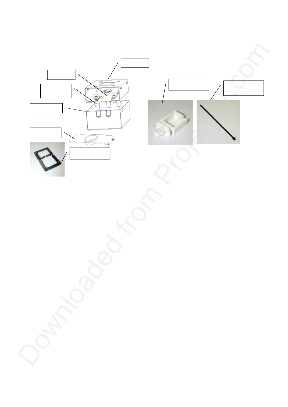
Illustration of the Cable Cover Assy:
Z348001
R826748
R347972
R826761
R347968 (7X)
G229790 &
V3675126
R826749
R826745
( 4 X)
Note: The assembly is used only when ceiling mount is mounted along with IQ bar for
hiding and guiding the cables.
( 4X)
Page 7

Mounting the Assembly
Necessary Tools
1.Torx screw driver for M3 screw
2. Hexagonal driver (n° 6)
3.Ring spanner 12-13
4.Side spanner 12-13
5. Cross head screw driver for M8 Screw
Centering the ceiling mount
Mark the position on the ceiling hole. Since the center of the lens does not coincide with the center
of the projector, the center of the lens has been marked on the ceiling mount.
Page 8

Remark
The horizontal shift of the ceiling mount allows to reenter the projector later on, However, centering
decently the base plate insures a good horizontal shift margin afterwards.
Mounting the Assembly
The fixation can be done with standard M8 bolt ( not supplied)
Page 9

Projector preparation:
r818903.
Nut M8
1.Turn the projector to its back and remove the Feet assembly. Unscrew 3 Plastic feet and
remove their X head M8 screws. Discard 3 plastic feet r722567 and x head M8 screw.
R722567, M8
SCREW,
SPRING WASHER
& FEET SUPPORT
2.Fix the feet support, spring washer and Spacer M8 bolt as shown below. For alignment of
the Centre distance between the feet, fix the ceiling mount and then tight the spacer M8.
Remove the Ceiling mount and fix it on the Ceiling.
Feet Support
R818903, Spring
Washer , Spacer M8
R826744 and Flange
Page 10

3.Lift and slide the projector assembly into the Ceiling mount. The projector will be located
Slide
Lift
precisely into the ceiling mount base plate after the tightening of 3 M 8 flange Nuts.
4.Route the Signal cable (RGBHV or Deserialiser ) and Power cord into the cable saddles.
5.Fix the one end of safety chain into the projector’s Eye bolt and the other end to the firm place
in the Ceiling.
Page 11

Adjustments: Following adjustment can be done in random order.
Shift parallel to
B
Up/down
Rotate around central
C
A
B
screen
50 mm
± 10°
tilt
Axis ±3°
horizontal
1. Shift parallel to the screen:
Loosen the 2 bolts A and move the projector till the projector is aligned. Tighten these 2 bolts to
secure the position.
2. Up down Tilt :
Loosen the 4 bolts B . Adjust the updown tilt precisely by moving bolt C clockwise or anti clockwise.
Tighten the 4 bolts B to secure the position.
Page 12

F
Rotate around
E
G
Rotate around
vertical axis
central
±5°
F
c
Axis ±3°
horizontal
entral
3. Rotate around central Vertical axis:
Loosen the 4 bolts E . Rotate/adjust the projector clockwise or anti clockwise. Tighten the 4 bolts
E to secure the position.
4. Rotate around central Horizontal axis:
Loosen the 4 bolts F . Adjust the motion precisely by moving bolt G clockwise or anti clockwise.
Tighten the 4 bolts F to secure the position.
Page 13

Mounting the bar with Cable Cover assembly:
K
J
1.Unscrew the 2 bolts J and slide out the upper part of the Bar. Pass the cable cover into the
upper part of the Bar.
2.Slide the horizontal shift plate R 826743 into the lower part of the Bar. Fix with 4 M8 bolt K.
3.Slide the upper bar into the lower bar assembly. Remount the 2 previously removed bolt J.
Adjust the height to minimum.
Page 14

4.Routing the Cables:
a.RGBHV cable preparation: With the help of PVC tape arrange the connectors in
series. Pass the cable RGBHV , Deserialiser and power cord into cable guide R826761
b.Pass the RGBHV cable into the IQ bar assembly from top side. Take out the BNC
connector one by one from bottom side.
c.Pass the power cord and deserialiser cable one by one.
Page 15

d.Pass all the cables one by one from cable guide R 826745 and fix the cable guide on to
L
M
the hor shift plate using 2 M3 Screws L.
The cable routing through IQ bar is complete. Adjust the approximate height of the IQ bar
and also adjust the length of the cable required at the projector side.
5.Mount the Ceiling Bracket R 826748 on to the ceiling with standard M8 bolt not supplied with
the Kit. For marking of the ceiling holes, refer the Installation manual of the Ceiling Mount of
CV 120.
6. Hang on the IQ bar and cable routed assembly. Fix with 4 M8 bolt along with washer M.
Page 16

7.Mount the Ceiling mount assembly on to the horizontal shift plate by twisting and then lifting
A
up. Fix the 2 M8 Bolt A.
8. Route the deserialiser cable and the power cord to the back and RGB cable to the front.
Power cord &
Deserialiser cable
RGB Cable
Page 17

There is also an option to route the cable from inside the Ceiling mount using cable ties and guiding
Cable Tie
Cable guide
holes on the Ceiling mount base as shown below.
Cable Ties
RGB cables
Power cord &
Deserialiser cable
Break the cable guide grooves on the cable cover as per the direction and location of the input
cables and power cord at customer site/room. Lift the cable cover and fix with the help 4 M3 screws
N.
Cable Guide
Grooves
N
Page 18

O
9.The adjustment procedure for the rotation around central vertical axis can also be done as
explained below.
Loosen the 4 M3 screws N of cable cover and slide it down word. Loosen the 4 bolts O.
Rotate /adjust the projector clockwise or anti clockwise. Tighten the 4 bolts O to secure the
position. Slide up the cable cover and fix 4 M3 screws N.
O
Rotate around
centralvertical axis
±5°
10.Fix the one end of safety chain into the projector’s Eye bolt and the other end to the firm place
in the Ceiling.
Page 19

Page 20

PLEASE READ
We are in no way responsible for the
contents of the manual. We do not guarantee
its accuracy and we do not make any claim
of copyright. The copyright remains the
property of their respective owners.
Visit the site to read the latest projector
news and reviews, read and comment on
projector specifications, download user
manuals and much more.
 Loading...