

Page 1
The bluetooth name and Bluetooth registered trademarks are owned by Bluetooth SIG, Inc., and are used by Baracoda under license. The Baracoda names and Baracoda trademarks are
own by Baracoda. All specifi cation are subject to change without notice - Non contractual pictures © Baracoda - All rights reserved
Baracoda, Inc. (US Offi ce) Baracoda SA (Europe Offi ce: France)
45 Main street - Suite 616 - Brooklyn, NY 11201 30 Avenue de l’Amiral Lemonnier - 78160 Marly-Le-Roi
Ph: 718 488 9600 - Fx: 718 488 9601 Ph: +33 1 30 08 89 00 - Fx: +33 1 30 08 89 98
Important notice
Every effort is made to ensure the accuracy of
our product information; however, we accept no
responsability for errors or omissions including, but not
limited to, the implied warranties of merchantability and
fi tness for a particular purpose. We shall not be liable for
errors contained herein or for incidental consequential
damages in connection with the furnishing, performance,
or use of this material.
Specifi cations or version may be subject to change
without notice. The actual specifi cation and version are
based on the product delivered.
Introduction
Scanning a series of programming bar code labels can
confi gure the scanner.
The scanner must be properly powered before program-
ming.
Programming Guide
Page 2

BCM2604-F Programming guide
This document is to be used with the following Baracoda Barcode Scanners:
BCM2604-F
Important notice:
Every effort is made to ensure the accuracy of our product information; however, we accept no responsibility for errors or
omissions including, but not limited to, the implied warranties of merchantability and fitness for a particular purpose. We shall not be liable for
errors contained herein or for incidental consequential damages in connection with the furnishing, performance, or use of this material.
Specifications or version may be subject to change without notice. The actual specification and version are based on the product
delivered.
1
Page 3

1
2
BCM2604-F Programming Guide
RESET ALL PARAMETERS...................................................................................................................... 4
OUTPUT....................................................................................................................................................... 5
2.1
B
EEPER – GOOD READ
2.2
B
EEPER VOLUME – GOOD READ
2.3
B
EEPER PITCH – GOOD READ
2.4
B
EEPER DURATION – GOOD READ
2.5
N
UMBER OF BEEPS – GOOD READ
2.6
G
OOD READ DELAY
2.7
A
IMER DELAY
2.8
C
ENTERING
2.9
D
ECODE SEARCH MODE
2.10 O
2.11 O
2.11.1 Output Sequence Editor
2.11.2 Require Outpu Sequence
2.12 NO R
2.13 P
2.14 V
2.15 W
2.16 P
UTPUT SEQUENCE OVERVIEW
UTPUT SEQUENCE EXAMPLE
EAD
RINT WEIGHT
IDEO REVERSE
ORKING ORIENTATION
REFIX SUFFIX
....................................................................................................................................... 6
.......................................................................................................................................... 7
............................................................................................................................................ 11
................................................................................................................................... 11
................................................................................................................................. 11
................................................................................................................................... 12
....................................................................................................................... 5
....................................................................................................... 5
............................................................................................................ 5
..................................................................................................... 5
.................................................................................................... 6
............................................................................................................................ 6
..................................................................................................................... 8
.......................................................................................................... 8
............................................................................................................ 9
...................................................................................................... 10
t
................................................................................................................... 12
................................................................................................... 10
3
SYMBOLOGIES....................................................................................................................................... 13
3.1
R
ESET ALL PARAMETERS
3.2
A
LL SYMBOLOGIES ON AND OFF
3.3
M
ESSAGE LENGTH DESCRIPTION
3.4
C
ODABAR
3.4.1 Codabar Check Character
3.4.2 Codabar Check Character
3.4.3 Codabar Concatenation
3.4.4 Codabar Message Length
3.5
C
ODE
3.5.1 Code 39 Sta t/Stop Characters
3.5.2 Code 39 Check Character
3.5.3 Code 39 Message Length
3.5.4 Code 39 Append
3.5.5 Code 32 Pharmaceutical (PARAF)
3.5.6 Full ASCII
3.5.7 Code 39 Code Page
3.6
I
NTERLEAVED 2 OF
3.6.1 Check Digit
3.6.2 Interleaved 2 of 5 Message Length
3.7
C
ODE
3.7.1 Code 93 Message Length
3.7.2 Code 93 Code Page
3.8
C
ODE 2 OF
3.8.1 Code 2 of 5 Message Length
........................................................................................................................................... 14
39 ...........................................................................................................................................16
..................................................................................................................................... 17
................................................................................................................................. 19
93 ...........................................................................................................................................19
5 ..................................................................................................................................... 20
.................................................................................................................... 13
..................................................................................................... 13
..................................................................................................... 13
....................................................................................................... 14
....................................................................................................... 14
............................................................................................................ 15
........................................................................................................ 15
r
....................................................................................................................... 17
................................................................................................................. 18
5.......................................................................................................................... 18
................................................................................................................. 20
.............................................................................................. 16
....................................................................................................... 16
........................................................................................................ 17
......................................................................................... 17
........................................................................................ 19
........................................................................................................ 20
.................................................................................................. 20
2
Page 4

3.9
IATA C
3.9.1 IATA Code 2 of 5 Message Length
3.10 M
3.10.1 Matrix 2 of 5 Message Length
3.11 C
3.11.1 Check Digits Required
3.11.2 Code 11 Message Length
3.12 C
3.12.1 ISBT 128 Concatenation
3.12.2 Code 128 Message Length
3.12.3 Code 128 Code Page
3.13 T
3.13.1 Telepen Ou put
3.13.2 Telepen Message Length
3.14 UPC A ............................................................................................................................................... 24
3.14.1 UPC-A Check Digit
3.14.2 UPC-A Numbe Sys em
3.14.3 UPC-A Addenda
3.14.4 UPC-A Addenda Required
3.14.5 UPC-A Addenda Separator
3.14.6 UPC-A/EAN-13 with Extended Coupon Code
3.14.7 UPC-E0
3.14.8 UPC-E0 Expand
3.14.9 UPC-E0 Addenda Required
3.14.10 UPC-E0 Addenda Separator
3.14.11 UPC-E0 Check Digit
3.14.12 UPC-E0 Number System
3.14.13 UPC-E0 Addenda
3.14.14 UPC-E1
3.15 EAN/JAN-13..................................................................................................................................... 27
3.15.1 EAN/JAN-13 Check Digit
3.15.2 EAN/JAN-13 Addenda
3.15.3 EAN/JAN-13 Addenda Required
3.15.4 EAN/JAN-13 Addenda Separator
3.15.5 ISBN Translate
3.16 EAN/JAN-8....................................................................................................................................... 29
3.16.1 EAN/JAN-8 Check Digit
3.16.2 EAN/JAN-8 Addenda
3.16.3 EAN/JAN-8 Addenda Required
3.16.4 EAN/JAN-8 Addenda Separator
3.17 MSI .................................................................................................................................................... 30
3.17.1 MSI Check Charac er
3.17.2 MSI Message Length
3.18 P
3.18.1 Plessey Message Length
3.19 RSS ................................................................................................................................................... 31
3.19.1 RSS-14
3.19.2 RSS Limited
3.19.3 RSS Expanded
3.19.4 RSS Expanded Message Length
3.20 P
3.20.1 PosiCode A and B
3.20.2 PosiCode Message Length
3.21 T
3.22 C
3.22.1 Codablock F Message Length
3.23 C
3.23.1 Code 16K Message Length
ODE 2 OF
ATRIX 2 OF
ODE
11 ...........................................................................................................................................22
ODE
128......................................................................................................................................... 22
ELEPEN
LESSEY CODE
OSICODE
RIOPTIC CODE
............................................................................................................................................. 23
ODABLOCK
ODE
16K......................................................................................................................................... 34
5............................................................................................................................ 21
........................................................................................ 21
5................................................................................................................................... 21
............................................................................................. 21
......................................................................................................... 22
................................................................................................... 22
..................................................................................................... 22
................................................................................................. 23
.......................................................................................................... 23
t
...................................................................................................................... 23
..................................................................................................... 24
............................................................................................................... 24
r t
.................................................................................................................... 25
................................................................................................................................... 26
..................................................................................................................... 26
................................................................................................................................... 27
....................................................................................................................... 29
.................................................................................................................................. 31
................................................................................................................................... 31
........................................................................................................................... 32
....................................................................................................................... 32
......................................................................................................................................... 32
................................................................................................................................. 33
F................................................................................................................................... 33
........................................................................................................ 24
................................................................................................... 25
................................................................................................. 25
................................................................. 25
................................................................................................ 26
............................................................................................... 26
............................................................................................................. 26
..................................................................................................... 27
.................................................................................................................. 27
..................................................................................................... 28
.......................................................................................................... 28
........................................................................................ 28
....................................................................................... 28
....................................................................................................... 29
............................................................................................................ 29
........................................................................................... 30
......................................................................................... 30
t
........................................................................................................... 30
............................................................................................................ 31
..................................................................................................... 31
........................................................................................ 32
................................................................................................................. 32
................................................................................................. 33
............................................................................................ 33
................................................................................................. 34
3
Page 5

3.24 C
3.24.1 Code 49 Message Length
3.25 PDF417 ............................................................................................................................................ 35
3.25.1 PDF417 Message Length
3.25.2 MicroPDF417
3.25.3 MicroPDF417 Message Length
3.26 EAN~UCC C
3.26.1 UPC/EAN Version
3.26.2 EAN~UCC Composite Code Message Length
3.26.3 EAN~UCC Emu ationl
3.27 TCIF L
3.28 P
3.28.1 Postnet Check Digit
3.29 P
3.29.1 Planet Code Check Digit
3.30 B
3.31 C
3.32 K
3.33 A
3.34 J
3.35 C
3.35.1 China Post Message Length
3.36 K
3.36.1 Korea Post Message Length
3.37 QR C
3.37.1 Micro QR Code
3.38 D
3.38.1 Data Matrix Message Length
3.39 M
3.39.1 MaxiCode Message Length
3.40 A
3.40.1 Az ec Code Message Leng h
3.41 A
ODE
49 ...........................................................................................................................................34
................................................................................................... 34
.................................................................................................... 35
......................................................................................................................... 35
.......................................................................................... 35
OMPOSITE CODES
INKED CODE 39
OSTNET
LANET CODE
RITISH POST
ANADIAN POST
IX (NETHERLANDS) POST
USTRALIAN POST
APANESE POST
HINA POST
............................................................................................................................................ 37
.................................................................................................................................... 37
..................................................................................................................................... 37
................................................................................................................................. 38
.............................................................................................................................. 3 8
.................................................................................................................................. 38
....................................................................................................................................... 38
OREA POST
ODE
ATA MATRIX
AXICODE
ZTEC CODE
...................................................................................................................................... 39
........................................................................................................................................... 39
...................................................................................................................................... 40
.......................................................................................................................................... 40
...................................................................................................................................... 41
t t
ZTEC RUNES
..................................................................................................................................... 41
................................................................................................................. 36
(TLC39) ..................................................................................................... 37
.................................................................................................................. 38
..................................................................................................................... 39
..................................................................................................... 36
............................................................... 36
........................................................................................................... 36
.............................................................................................................. 37
..................................................................................................... 37
............................................................................................... 39
............................................................................................... 39
............................................................................................... 40
................................................................................................. 40
.............................................................................................. 41
APPENDIX A: SYMBOLOLY CHART ............................................................................................................ 42
APPENDIX B : ASCII CONVERSION CHART ............................................................................................. 44
APPENDIX C: CODE PAGE MAPPING OF PRINTED BAR CODES ...................................................... 46
APPENDIX D: SAMPLE SYMBOLS ............................................................................................................... 46
APPENDIX E : PROGRAMMING CHART..................................................................................................... 47
1 Reset all parameters
The reading of the "Default settings” label turns all the parameters back to default settings:
4
Page 6
2 Output
2.1 Beeper – Good Read
The beeper may be programmed
response to a good read indication. All error and menu beeps are still audible.
2.2 Beeper Volume – Good Read
The beeper volume codes modify the volume of the beep the imager emits on a good read.
On
or
Off
in response to a good read. Turning this option off, only turns off the beeper
Default = On.
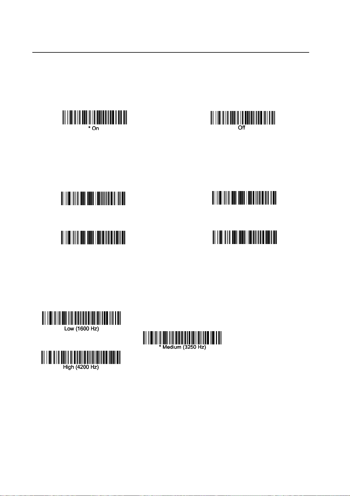
Default =, High..
Low
High
Medium
2.3 Beeper Pitch – Good Read
The beeper pitch codes modify the pitch (frequency) of the beep the imager emits on a good read.
Off
Default = Medium.
2.4 Beeper Duration – Good Read
The beeper duration codes modify the length of the beep the imager emits on a good read.
Default = Normal.
5
Page 7
* Normal Beep
Short Beep
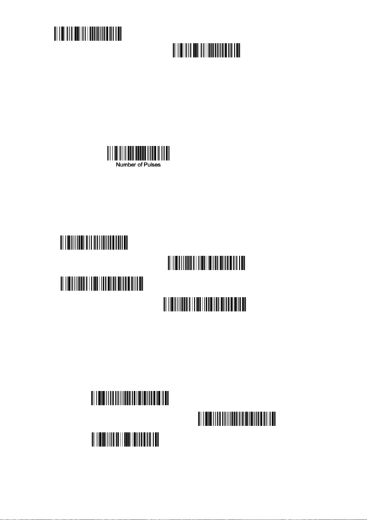
2.5 Number of Beeps – Good Read
The number of beeps of a good read can be programmed from 1 – 3 (maximum 3). The same number of
beeps will be applied to the beeper and LED in response to a good read. For example, if you program
this option to have two beeps, there will be two beeps and two LED flashes in response to a good
read. The beeps and LED flashes are in sync with one another. To change the number of beeps, scan
the bar code below and then scan a digit (1-3) bar code and the
Chart (Appendix E of this manual).
Default = One.
Save
bar code on the Programming
2.6 Good Read Delay
This sets the minimum amount of time before the imager can read another bar code.
* No Delay
Short Delay (500 ms)
Medium Delay (1,000 ms)
Long Delay (1,500 ms)
Default = No Delay.
2.7 Aimer Delay
The aimer delay allows a delay time for the operator to aim the imager before the picture is taken. Use
these codes to set the time between when the trigger is activated and when the picture is taken.
During the delay time, the aiming light will appear, but the LEDs won’t turn on until the delay time is
over
200 milliseconds
400 milliseconds
* Off
(no delay)
6
Page 8
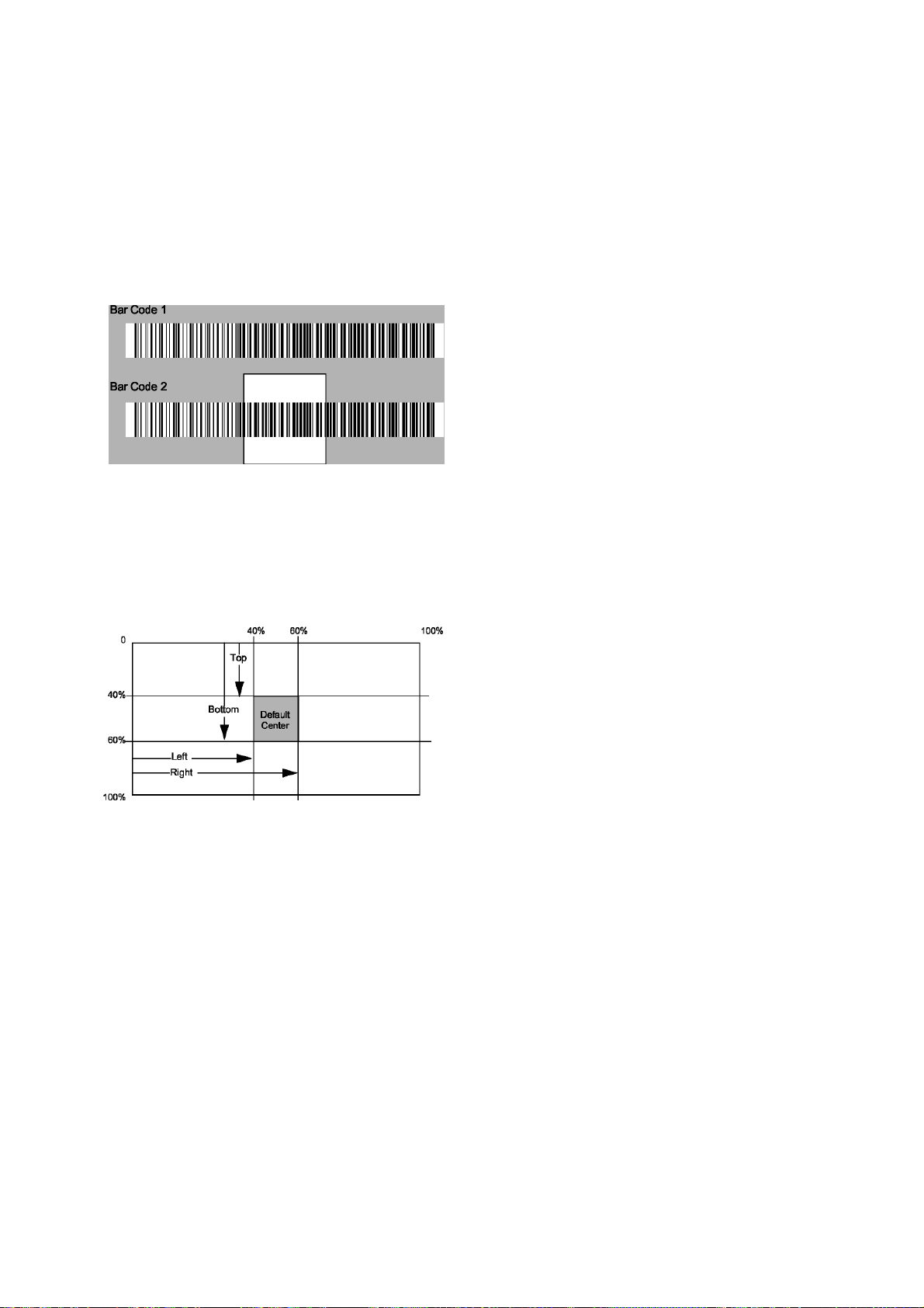
2.8 Centering
Use Centering to narrow the imager’s field of view to make sure the imager reads only those bar
codes intended by the user. For instance, if multiple codes are placed closely together, centering will
insure that only the desired codes are read. (Centering can be used in conjunction with Aimer Delay,
page 5-11, for the most error-free operation in applications where multiple codes are spaced closely
together. Using the Aimer Delay and Centering features, the imager can emulate the operation of
older systems, such as linear laser bar code imagers.)
In the example below, the gray area is the full imager field of view and the white area is the centering
window. Bar Code 1 will not be read, while Bar Code 2 will be.
The default centering window is a 128x96 pixel area in the center of the imager’s field of view. The
following diagram illustrates the default top, bottom, left, and right pixel positions, measured from the
top and the left side of the imager’s field of view, which is 640 by 480 pixels.
Scan Centering On, then scan one of the following bar codes to change the top, bottom, left, or right
of the centering window. Then scan the percent you want to shift the centering window using digits
on the inside back cover of this manual. Scan Save. Default Centering = 40% for Top and Left, 60%
for Bottom and Right.
7
Page 9

w
Centering On
* Centering Off
Top of Centering Window
Bottom of Centering Windo
Left of Centering Window
Right of Centering Window
2.9 Decode Search Mode
There are three selectable decode (scanning) modes:
Full Omnidirectional - Searches for bar code features beginning at the center of an image, and
searches to the image’s limits. This mode reads all symbologies , in any orientation. The Full
Omnidirectional search is very thorough which may slow performance time.
Note: This search mode is the default setting
Quick Omnidirectional - This is an abbreviated search for bar code features around the center region
of an image. This mode quickly reads all symbologies in any orientation. The Quick Omnidirectional
mode may miss some off-center symbols, as well as larger Data Matrix and QR Code symbols.
Quick Omnidirectional
Advanced Linear Decoding - Performs quick horizontal linear scans in a center band of the image.
This mode is not omnidirectional, but does quickly read linear and stacked bar codes. Advanced
Linear Decoding cannot read 2D, OCR, or Postal symbols.
2.10 Output Sequence Overview
Advanced Linear Decoding
Require Output Sequence
When turned off, the bar code data will be output to the host as the Imager decodes it. When turned
on, all output data must conform to an edited sequence or the Imager will not transmit the output data
to the host device.
Note: This selection is unavailable when the Multiple Symbols Selection is turned on.
Output Sequence Editor
8
Page 10

This programming selection allows you to program the Imager to output data (when scanning more
than one symbol) in whatever order your application requires, regardless of the order in which the bar
codes are scanned. Reading the Default Sequence symbol programs the Imager to the Universal
values, shown below. These are the defaults. Be certain you want to delete or clear all formats before
you read the Default Sequence symbol.
Note: To make Output Sequence Editor selections, you’ll need to know the code I.D., code length,
and character match(es) your application requires. Use the Alphanumeric symbols (Appendix E)
to read these options.
To Add an Output Sequence
1. Scan the Enter Sequence symbol (see Output Sequence Editor, in two pages).
2. Code I.D.
On the Symbology Chart on Appendix A, find the symbology to which you want to apply the
output sequence format. Locate the Hex value for that symbology and scan the 2 digit hex value
from the Programming Chart (Appendix E).
3. Length
Specify what length (up to 9999 characters) of data output will be acceptable for this symbology.
Scan the four digit data length from the Programming Chart. (Note: 50 characters is entered as
0050. 9999 is a universal number, indicating all lengths.) When calculating the length, you must
count any programmed prefixes, suffixes, or formatted characters as part of the length (unless
using 9999).
4. Character Match Sequences
On the ASCII Conversion Chart (Appendix B), find the Hex value that represents the character(s)
you want to match. Use the Programming Chart to read the alphanumeric combination that
represents the ASCII characters. (99 is the Universal number, indicating all characters.)
5. End Output Sequence Editor
Scan F F to enter an Output Sequence for an additional symbology, or Save to save your entries.
Other Programming Selections
~ Discard
This exits without saving any Output Sequence changes.
2.11 Output Sequence Example
In this example, you are scanning Code 93, Code 128, and Code 39 bar codes, but you want the
imager to output Code 39 1 st, Code 128 2nd, and Code 93 3rd, as shown below.
Note: Code 93 must be enabled to use this example.
9
Page 11

You would set up the sequence editor with the following command line:
SEQBLK62999941FF6A999942FF69999943FF
The breakdown of the command line is shown below:
SEQBLKsequence editor start command
62 code identifier for Code 39
9999 code length that must match for Code 39, 9999 = all lengths 41 start character match for
Code 39, 41h = “A” FF termination string for first code
6A code identifier for Code 128
9999 code length that must match for Code 128, 9999 = all lengths 42 start character match for
Code 128, 42h = “B” FF termination string for second code
69 code identifier for Code 93
9999 code length that must match for Code 93, 9999 = all lengths 43 start character match for
Code 93, 43h = “C” FF termination string for third code
To program the previous example using specific lengths, you would have to count any
programmed prefixes, suffixes, or formatted charact ers as part o f the length. If you use t he
example on the previous, assume a <CR> suffix and
specific code lengths, you would u se the following command line:
SEQBLK62001141FF6A001242FF69001143FF
The breakdown of the command line is shown below:
SEQBLK sequence editor start command 62 code identifier for
Code 39
0011 Code 39 code length (9) plus CR suffix (2) = 11
41 start character match for Code 39, 41h = “A”
FF termination string for first code
6A code identifier for Code 128
0012 Code 128 code length (10) plus CR suffix ( 2) = 12
42 start character match for Code 128, 42h = “B”
FF termination string for second code
69 code identifier for Code 93
0011 Code 93 code length (9) plus CR suffix (2) = 11
43 start character match for Code 93, 43h = “C”
FF termination string for third code
2.11.1 Output Sequence Editor
Enter Sequence
Default Sequence
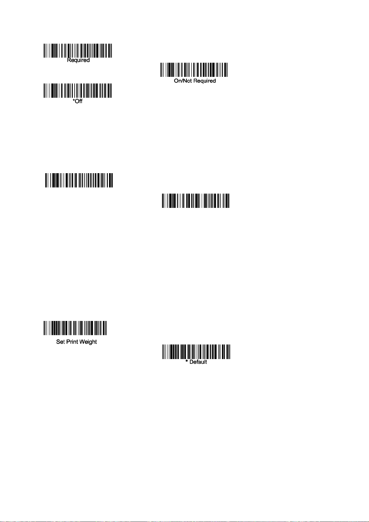
2.11.2 Require Output Sequence
When an output sequence is Required, all output data mu st conform to an edited seq uence or
the imager will not transmit the outp ut dat a to the host d evice. When it ’s On/Not Required, the
imager will attempt to get the output data to conform to an edited sequen ce, but if it cannot, the
imager transmits all output data to the host device as is.
When the output sequence is Off, t he bar co de dat a is outpu t to th e host as t he imager deco des
it. Note: This selection is unavailable when th e Multip le Symbols Se lection is t urned on.
10
Page 12
2.12 No Read
With No Read turned
Scan Data Window, an “NR” appears when a code cannot be read. If No Read is turned
“NR” will not appear.
On
If you want a different notation than “NR,” for example, “Error,” or “Bad Code,” you can edit the
output message using the Data Formatter. The hex code for the No Read symbol is 9C.
On,
the Imager notifies you if a code cannot be read. If using a Quick*View
* Off
Off,
the
2.13 Print Weight
Print Weight is used to adjust the way the imager reads Matrix symbols. If a imager will be seeing
consistently heavily printed matrix symbols, then a print weight of 6 may improve the reading
performance. For consistently light printing, a print weight of 2 may help. After scanning the Set Print
Weight bar code, set the print weight (from 1-7) by scanning digits from the inside back cover, then
scanning Save. Default = 4.
2.14 Video Reverse
Video Reverse is used to allow the imager to read bar codes that are inverted. The “Off” bar code
below is an example of this type of bar code. If additional menuing is required, Video Reverse must be
disabled to read the menu bar codes and then re-enabled after menuing is completed.
Note: Images downloaded from the unit will not be reversed. This is a setting for decoding only.
11
Page 13
On
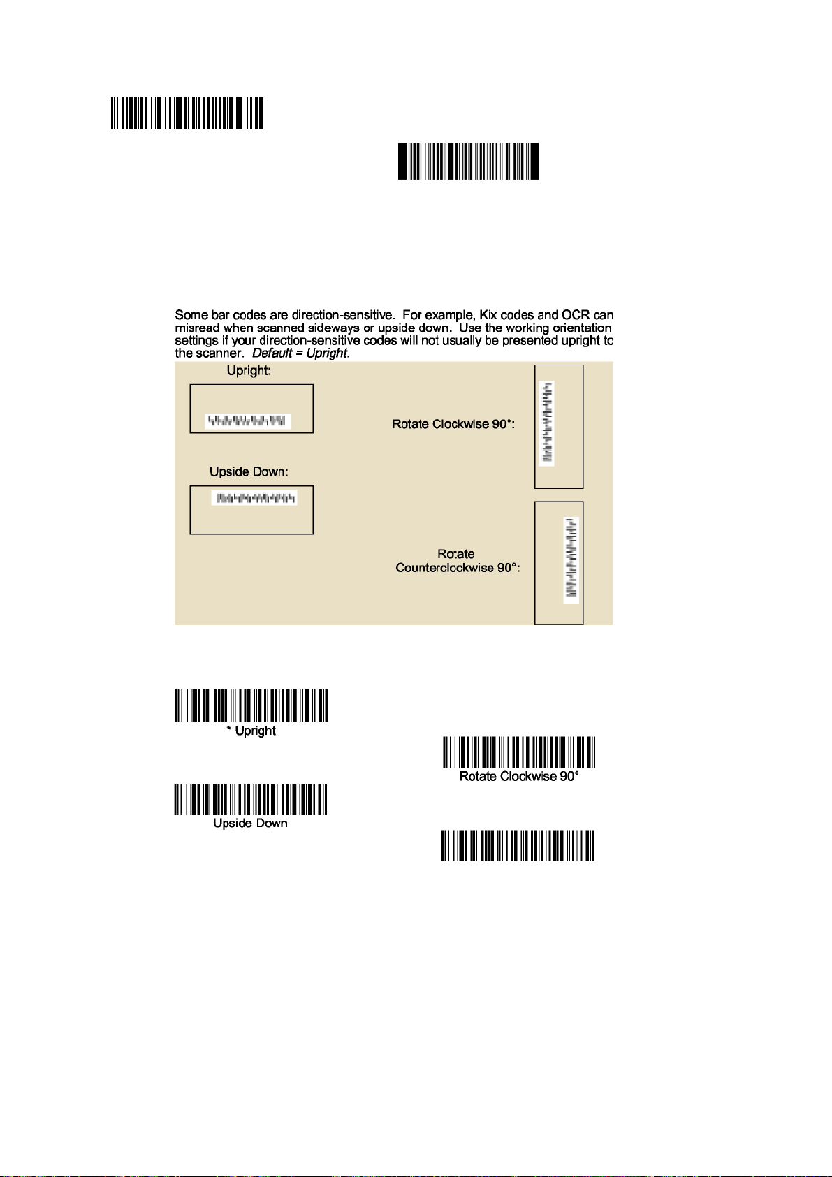
2.15 Working Orientation
* Off
2.16 Prefix Suffix
It is of course possible to add a suffix/prefix but not via this programming guide. It is only possible
sending commands via Bluetooth. Please refer to the BaracodaManager documentation for further
information.
Rotate Counterclockwise 90°
12
Page 14
3 Symbologies
This programming section contains the following menu selections
Linear barcodes
Codabar, Code 39, Interleaved 2 of 5, Code 93, EAN, Code 2 of 5, IATA Code 2 of 5, Matrix 2 of
5, Code 11, Code 128, Telepen, UPC A, UPC-A/EAN-13 with Extended Coupon Code, EAN/JAN
13, EAN/JAN 8, MSI, Plessey Code, RSS-14, RSS Limited, RSS Expanded, PosiCode A and B
Stacked barcodes
Code49, Code 16K, PDF417, Macro PDF417, Micro PDf417, EAN/UCC composite codes, RSS
stacked and composite, Trioptic, TLC39, Codablock F
Postal Barcodes
Postnet, Planet Code, British Post, Canadian Post, Kix (Netherlands)Post, Australian Post, Japanese
Post, China Post, Korea Post,
2D Barcodes
QR Code, DataMatrix, MaxiCode, Aztec Code
3.1 Reset all parameters
The reading of the "Default settings” label turns all the parameters back to default settings:
3.2 All Symbologies On and Off
If you want to decode all the symbologies allowable for your imager, scan the All Symbologies On
code. If on the other hand, you want to decode only a particular symbology, scan All Symbologies Off
followed by the On symbol for that particular symbology.
All Symbologies On
All Symbologies Off
3.3 Message Length Description
You are able to set the valid reading length of some of the bar code symbologies. If the data length of
the scanned bar code doesn’t match the valid reading length, the imager will issue an error beep.
You may wish to set the same value for minimum and maximum length to force the imager to read
fixed length bar code data. This helps reduce the chances of a misread.
13
Page 15
EXAMPLE: Decode only those bar codes with a count of 9-20 characters.
Min. length = 09 Max. length = 20
EXAMPLE: Decode only those bar codes with a count of 15 characters.
Min. length = 15 Max. length = 15
For a value other than the minimum and maximum message length defaults, scan the bar codes
included in the explanation of the symbology, then scan the digit value of the message length and
Save bar codes on the Programming Chart (Appendix E of this manual). The minimum and maximum
lengths and the defaults are included with the respective symbologies.
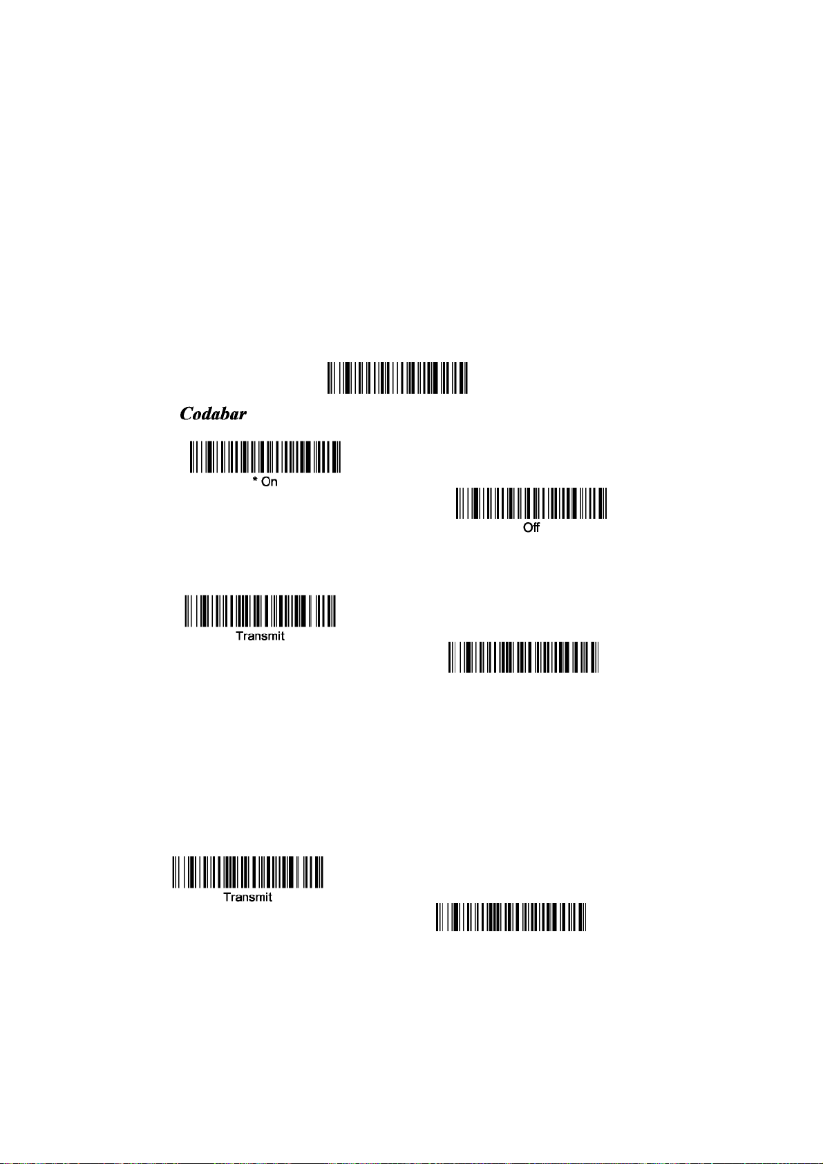
3.4 Codabar
<Default All Codabar Settings>
Codabar Start/Stop Characters
3.4.1 Codabar Check Character
Default = Don’t Transmit
3.4.2 Codabar Check Character
Codabar check characters are created using different “modulos.” You can program the imager to
read only Codabar bar codes with Modulo 16 check characters. Default = No Check Character.
14
Page 16

No Check Character indicates that the imager reads and transmits bar code data with or without a
check character.
When Check Character is set to Validate and Transmit, the imager will only read Codabar bar codes
printed with a check character, and will transmit this character at the end of the scanned data.
When Check Character is set to Validate, but Don’t Transmit, the unit will only read Codabar bar
codes printed with a check character, but will not transmit the check character with the scanned
data.
Validate Modulo 16
and Transmit
3.4.3 Codabar Concatenation
Codabar supports symbol concatenation. When you enable concatenation, the imager looks for a
Codabar symbol having a “D” start character, adjacent to a symbol having a “D” stop character. In
this case the two messages are concatenated into one with the “D” characters omitted. Default =
On.
Character start
Select Require to prevent the imager from decoding a single “D” Codabar symbol without its
companion. This selection has no effect on Codabar symbols without Stop/Start D characters.
* On
Off
Require
3.4.4 Codabar Message Length
Scan the bar codes below to change the message length. Refer to Message Length Description
(chapt 3.2) for additional information. Minimum and Maximum lengths = 2-60. Minimum Default = 4,
15
Page 17

Maximum Default = 60.
Minimum Message Length
3.5 Code 39
< Default All Code 39 Settings >
Maximum Message Length
3.5.1 Code 39 Start/Stop Characters
Start/Stop characters identify the leading and trailing ends of the bar code. You may either transmit,
or not transmit Start/Stop characters. Default = Don’t Transmit
3.5.2 Code 39 Check Character
No Check Character indicates that the imager reads and transmits bar code data with or without a
check character.
When Check Character is set to Validate, but Don’t Transmit, the unit only reads Code 39 bar codes
printed with a check character, but will not transmit the check character with the scanned data.
When Check Character is set to Validate and Transmit, the imager only reads Code 39 bar codes
printed with a check character, and will transmit this character at the end of the scanned data. Default
= No Check Character.
* No Check Character
Validate and Transmit
Validate, but Don’t Transmit
16
Page 18

3.5.3 Code 39 Message Length
Scan the bar codes below to change the message length. Refer to Message Length Description
(chapt 3.2) for additional information. Minimum and Maximum lengths = 0-48. Minimum Default = 0,
Maximum Default = 48.
Minimum Message Length
3.5.4 Code 39 Append
Maximum Message Length
This function allows the imager to append the data from several Code 39 bar codes together before
transmitting them to the host computer. When this function is enabled, the imager stores those Code
39 bar codes that start with a space (excluding the start and stop symbols), and does not
immediately transmit the data. The imager stores the data in the order in which the bar codes are
read, deleting the first space from each. The imager transmits the appended data when it reads a
Code 39 bar code that starts with a character other than a space. Default = Off.
3.5.5 Code 32 Pharmaceutical (PARAF)
Code 32 Pharmaceutical is a form of the Code 39 symbology used by Italian pharmacies. This
symbology is also known as PARAF.
Note: Trioptic Code must be turned off while scanning Code 32 Pharmaceutical codes.
On
* Off
3.5.6 Full ASCII
If Full ASCII Code 39 decoding is enabled, certain character pairs within the bar code symbol will
be interpreted as a single character. For example: $V will be decoded as the ASCII character SYN,
and /C will be decoded as the ASCII character #. Default = On.
17
Page 19
NUL %U DLE $P SP SPA
A
SOH $A DC1 $Q ! /A 1 1 A A Q Q a +A q +Q
STX $B DC2 $R
ETX $C DC3 $S # /C 3 3 C C S S c +C s +S
EOT $D DC4 $T $ /D 4 4 D D T T d +D t +T
ENQ $E NAK $U % /E 5 5 E E U U e +E u +U
CK $F SYN $V & /F 6 6 F F V V f +F v +V
BEL $G ETB $W
BS $H CAN $X ( /H 8 8 H H X X h +H x +X
HT $I EM $Y ) /I 9 9 I I Y Y i +I y +Y
LF $J SUB $Z * /J : /Z J J Z Z j +J z +Z
VT $K ESC %A + /K ; %F K K [ %K k +K { %P
FF $L FS %B , /L < %G L L \ %L l +L | %Q
CR $M GS %C - - = %H M M ] % m +M } %R
SO $N RS %D . . > %I N N ^ %N n +N ~ %S
SI $O US %E / /O ? %J O O _ %O o +O DEL %T
“
‘
0 0 @ %V P P ‘ %Wp +P
CE
/B 2 2 B B R R b +B r +R
/G 7 7 G G W W g +G w +W
Character pairs /M and /N decode as a minus sign and period respectively. Character pairs /P
through /Y decode as 0 through 9.
Full ASCII On
* Full ASCII Off
3.5.7 Code 39 Code Page
Code pages define the mapping of character codes to characters. If the data received does not
display with the proper characters, it may be because the bar code being scanned was created using
a code page that is different from the one the host program is expecting. If this is the case, scan the
bar code below, select the code page with which the bar codes were created (see Code Page
Mapping of Printed Bar Codes on page A-6), and scan the value and the Save bar code from the
Programming Chart (Appendix E of this manual). The data characters should then appear properly.
Code 39 Code Page
3.6 Interleaved 2 of 5
< Default All Interleaved 2 of 5 Settings >
18
Page 20

Interleaved 2 of 5
* On
Off
3.6.1 Check Digit
No Check Digit indicates that the imager reads and transmits bar code data with or without a check
digit.
When Check Digit is set to Validate, but Don’t Transmit, the unit only reads Interleaved 2 of 5 bar
codes printed with a check digit, but will not transmit the check digit with the scanned data.
When Check Digit is set to Validate and Transmit, the imager only reads Interleaved 2 of 5 bar codes
printed with a check digit, and will transmit this digit at the end of the scanned data. Default = No
Check Digit
3.6.2 Interleaved 2 of 5 Message Length
Scan the bar codes below to change the message length. Refer to Message Length Description
(chapt 3.2) for additional information. Minimum and Maximum lengths = 2-80. Minimum Default = 4,
Maximum Default = 80
Minimum Message Length
Maximum Message Length
3.7 Code 93
< Default All Code 93 Settings >
Code 93
19
Page 21

* On
Off
3.7.1 Code 93 Message Length
Scan the bar codes below to change the message length. Refer to Message Length Description
(chapt 3.2) for additional information. Minimum and Maximum lengths = 0-80. Minimum Default = 0,
Maximum Default = 80.
Maximum Message Length
3.7.2 Code 93 Code Page
Code pages define the mapping of character codes to characters. If the data received does not
display with the proper characters, it may be because the bar code being scanned was created
using a code page that is different from the one the host program is expecting. If this is the case,
scan the bar code below, select the code page with which the bar codes were created (see Code
Page Mapping of Printed Bar Codes on page A-6), and scan the value and the Save bar code from
the Programming Chart on the inside the back cover of this manual. The data characters should
then appear properly.
Code 93 Code Page
3.8
Code 2 of 5
<Default All Code 2 of 5 Settings>
Code 2 of 5
On
* Off
3.8.1 Code 2 of 5 Message Length
Scan the bar codes below to change the message length. Refer to Message Length Description for
additional information. Minimum and Maximum lengths = 1-48. Minimum Default = 4, Maximum
Default = 48.
20
Page 22

I
3.9 IATA Code 2 of 5
<Default All Code IATA 2 of 5 Settings>
ATA Code 2 of 5
3.9.1 IATA Code 2 of 5 Message Length
Scan the bar codes below to change the message length. Refer to Message Length Description
(chapt 3.2) for additional information. Minimum and Maximum lengths = 1-48. Minimum Default = 4,
Maximum Default = 48.
Maximum Message Length
3.10 Matrix 2 of 5
<Default All Matrix 2 of 5 Settings>
Maximum Message Length
Matrix 2 of 5
3.10.1 Matrix 2 of 5 Message Length
Scan the bar codes below to change the message length. Refer to Message Length Description
(chapt 3.2) for additional information. Minimum and Maximum lengths = 1-80. Minimum Default = 4,
Maximum Default = 80.
21
Page 23

Minimum Message Length
Maximum Message Length
3.11 Code 11
<Default All Code 11 Settings>
Code 11
3.11.1 Check Digits Required
This option sets whether 1 or 2 check digits are required with Code 11 bar codes.
Default = Two Check Digits.
3.11.2 Code 11 Message Length
Scan the bar codes below to change the message length. Refer to Message Length Description
(chapt 3.2) for additional information. Minimum and Maximum lengths = 1-80. Minimum Default = 4,
Maximum Default = 80
Minimum Message Length
Maximum Message Length
3.12 Code 128
<Default All Code 128 Settings>
3.12.1 ISBT 128 Concatenation
In 1994 the International Society of Blood Transfusion (ISBT) ratified a standard for communicating
critical blood information in a uniform manner. The use of ISBT formats requires a paid license. The
ISBT 128 Application Specification describes 1) the critical data elements for labeling blood
products, 2) the current recommendation to use Code 128 due to its high degree of security and its
22
Page 24

space-efficient design, 3) a variation of Code 128 that supports concatenation of neighboring
symbols, and 4) the standard layout for bar codes on a blood product label. Use the bar codes below
to turn concatenation on or off. Default=Off.
3.12.2 Code 128 Message Length
Scan the bar codes below to change the message length. Refer to Message Length Description
(chapt 3.2) for additional information. Minimum and Maximum lengths = 0-80. Minimum Default = 0,
Maximum Default = 80.
3.12.3 Code 128 Code Page
Code pages define the mapping of character codes to characters. If the data received does not
display with the proper characters, it may be because the bar code being scanned was created using
a code page that is different from the one the host program is expecting. If this is the case, scan the
bar code below, select the code page with which the bar codes were created (see Code Page
Mapping of Printed Bar Codes on page A-6), and scan the value and the Save bar code from the
Programming Chart on the inside the back cover of this manual. The data characters should then
appear properly. Default = 2.
Maximum Message Length
Code 128 Code Page
3.13 Telepen
Telepen
Telepen
3.13.1 Telepen Output
Using AIM Telepen Output, the imager reads symbols with start/stop pattern 1 and decodes them as
standard full ASCII (start/stop pattern 1). When Original Telepen Output is selected, the imager
reads symbols with start/stop pattern 1 and decodes them as compressed numeric with optional full
ASCII (start/stop pattern 2). Default = AIM Telepen Output.
<Default All Telepen Settings>
On
* Off
23
Page 25

3.13.2 Telepen Message Length
Original Telepen Output
Scan the bar codes below to change the message length. Refer to Message Length Description
(chapt 3.2) for additional information. Minimum and Maximum lengths = 1-60. Minimum Default = 1,
Maximum Default = 60.
Minimum Message Length
Maximum Message Length
3.14 UPC A
Default All UPC-A Settings
UPC A
* On
3.14.1 UPC-A Check Digit
This selection allows you to specify whether the check digit should be transmitted at the end of the
scanned data or not. Default = On.
* On
3.14.2 UPC-A Number System
The numeric system digit of a U.P.C. symbol is normally transmitted at the beginning of the scanned
data, but the unit can be programmed so it will not transmit it. Default = On.
Off
24
Page 26

3.14.3 UPC-A Addenda
2 Digit Addenda On
* 2 Digit Addenda Off
5 Digit Addenda On
* 5 Digit Addenda Off
3.14.4 UPC-A Addenda Required
When Required is scanned, the imager will only read UPC-A bar codes that have addenda. You must
then turn on a 2 or 5 digit addenda listed on page 820. Default = Not Required
* Not Required
3.14.5 UPC-A Addenda Separator
When this feature is on, there is a space between the data from the bar code and the data from the
addenda. When turned off, there is no space. Default = On.
* On
Off
3.14.6 UPC-A/EAN-13 with Extended Coupon Code
Use the following codes to enable or disable UPC-A and EAN-13 with Extended Coupon Code.
Default = On.
* On
25
Page 27
3.14.7 UPC-E0
Most U.P.C. bar codes lead with the 0 number system. For these codes, use the UPC-E0 selection. If
you need to read codes that lead with the 1 number system, use UPC-E1. Default = On.
* UPC E0 On
UPC E0 Off
3.14.8 UPC-E0 Expand
UPC-EO expands the UPC-E code to the 12 digit, UPC-A format. Default = Off
On
* Off
3.14.9 UPC-E0 Addenda Required
When Addenda Required is set to on, the imager will only read UPC-E bar codes that have addenda.
Default = Not Required.
Required
* Not Required
3.14.10 UPC-E0 Addenda Separator
When this feature is on, there is a space between the data from the bar code and the data from the
addenda. When turned off, there is no space. Default = Off.
* Off
3.14.11 UPC-E0 Check Digit
Check Digit specifies whether the check digit should be transmitted at the end of the scanned data or not. D efault = On.
Off
26
Page 28
3.14.12 UPC-E0 Number System
The numeric system digit of a U.P.C. symbol is normally transmitted at the beginning of the scanned
data, but the unit can be programmed so it will not transmit it. Default = On.
* On
Off
3.14.13 UPC-E0 Addenda
This selection adds 2 or 5 digits to the end of all scanned UPC-E data. Default = Off for both 2 Digit
and 5 Digit Addenda.
2 Digit Addenda On
* 2 Digit Addenda Off
5 Digit Addenda On
* 5 Digit Addenda Off
3.14.14 UPC-E1
Most U.P.C. bar codes lead with the 0 number system. For these codes, use UPC-E0. If you need to
read codes that lead with the 1 number system, use the UPC-E1 selection. Default = Off.
UPC E1 On
* UPC E1 Off
EAN/JAN-13
<Default All EAN/JAN Settings>
3.15 EAN/JAN-13
Off
27
Page 29

3.15.1 EAN/JAN-13 Check Digit
This selection allows you to specify whether the check digit should be transmitted at the end of the
scanned data or not. Default = On.
3.15.2 EAN/JAN-13 Addenda
This selection adds 2 or 5 digits to the end of all scanned EAN/JAN-13 data. Default = Off for both 2
Digit and 5 Digit Addenda
2 Digit Addenda On
* 2 Digit Addenda Off
* 5 Digit Addenda Off
3.15.3 EAN/JAN-13 Addenda Required
When Addenda Required is set to on, the imager will only read EAN/JAN-13 bar codes that have
addenda. Default = Not Required
Required
3.15.4 EAN/JAN-13 Addenda Separator
When this feature is on, there is a space between the data from the bar code and the data from the
addenda. When turned off, there is no space. Default = On.
* Not Required
On
Off
Note: If you want to enable or disable EAN13 with Extended Coupon Code, refer to UPC-A/EAN-13 w ith Extended
Coupon Code (page 8-21).
28
Page 30
3.15.5 ISBN Translate
N
-
8
This selection causes EAN-13 Bookland symbols to be translated into their equivalent ISBN number
format. Default = Off.
3.16 EAN/JAN-8
Defaults All Settings EAN/JAN-8
EAN/JA
3.16.1 EAN/JAN-8 Check Digit
This selection allows you to specify whether the check digit should be transmitted at the end of the
scanned data or not. Default = On.
3.16.2 EAN/JAN-8 Addenda
This selection adds 2 or 5 digits to the end of all scanned EAN/JAN-8 data. Default = Off for both 2
Digit and 5 Digit Addenda.
2 Digit Addenda On
* 2 Digit Addenda Off
5 Digit Addenda On
* 5 Digit Addenda Off
29
Page 31

3.16.3 EAN/JAN-8 Addenda Required
When Addenda Required is set to on, the imager will only read EAN/JAN-8 bar codes that have
addenda. Default = Not Required.
3.16.4 EAN/JAN-8 Addenda Separator
When this feature is on, there is a space between the data from the bar code and the data from the
addenda. When turned off, there is no space. Default = On.
* On
Off
3.17 MSI
<Default All MSI Settings>
MSI
3.17.1 MSI Check Character
Different types of check characters are used with MSI bar codes. You can program the imager to
read MSI bar codes with Type 10 check characters.
Default = Validate Type 10, but Don’t Transmit. When Check Character is set to Validate and
Transmit, the imager will only read MSI bar codes printed with the specified type check character,
and will transmit this character at the end of the scanned data.
When Check Character is set to Validate, but Don’t Transmit, the unit will only read MSI bar codes
printed with the specified type check character, but will not transmit the check character with the
scanned data.
Validate Type 10 an d Tra nsm it
30
Page 32

3.17.2 MSI Message Length
Scan the bar codes below to change the message length. Refer to Message Length Description
(chapt 3.2) for additional information. Minimum and Maximum lengths = 4-48. Minimum Default = 4,
Maximum Default = 48.
Minimum Message Length
Maximum Message Length
3.18 Plessey Code
<Default All Plessey Code Settings>
3.18.1 Plessey Message Length
Scan the bar codes below to change the message length. Refer to Message Length Description
(chapt 3.2) for additional information. Minimum and Maximum lengths = 4-48. Minimum Default = 4,
Maximum Default = 48.
Maximum Message Length
3.19 RSS
3.19.1 RSS-14
< Default All RSS-14 Settings >
31
Page 33

3.19.2 RSS Limited
< Default All RSS Limited Settings >
3.19.3 RSS Expanded
< Default All RSS Expanded Settings >
3.19.4 RSS Expanded Message Length
Scan the bar codes below to change the message length. Refer to Message Length Description
(chapt 3.2) for additional information. Minimum and Maximum lengths = 4-74. Minimum Default = 4,
Maximum Default = 74.
Minimum Message Length
3.20 PosiCode
* On
3.20.1 PosiCode A and B
* On
Maximum Message Length
<Default All PosiCode Settings>
Off
Off
32
Page 34

You have to have PosiCode A and B on to read any of the PosiCode symbologies.
A and B Limited B On (Limited A Off)
3.20.2 PosiCode Message Length
Scan the bar codes below to change the message length. Refer to Message Length Description
(chapt 3.2) for additional information. Minimum and Maximum lengths = 2-80. Minimum Default = 4,
Maximum Default = 48.
Minimum Message Length
Maximum Message Length
3.21 Trioptic Code
Note: If you are going to scan Code 32 Pharmaceutical codes Trioptic Code must be o ff. Trioptic Code is used for
labeling magnetic storage media.
On
* Off
3.22 Codablock F
<Default All Codablock F Settings>
On
* Off
3.22.1 Codablock F Message Length
Scan the bar codes below to change the message length. Refer to Message Length Description
(chapt 3.2) for additional information. Minimum and Maximum lengths = 1-2048. Minimum Default =
1, Maximum Default=2048.
33
Page 35
Minimum Message Length Maximum Message Length
3.23 Code 16K
<Default All Code 16K Settings
3.23.1 Code 16K Message Length
Scan the bar codes below to change the message length. Refer to Message Length Description
(chapt 3.2) for additional information. Minimum and Maximum lengths = 0-160. Minimum Default = 1,
Maximum Default = 160.
Minimum Message Length
Maximum Message Length
3.24 Code 49
<Default All Code 49 Settings>
Code 49
* On
Off
3.24.1 Code 49 Message Length
Scan the bar codes below to change the message length. Refer to Message Length Description
(chapt 3.2) for additional information. Minimum and Maximum lengths = 1-81. Minimum Default = 1,
Maximum Default = 81.
Minimum Message Length
Maximum Message length
34
Page 36

3.25 PDF417
< Default All PDF417 Settings >
PDF417
* On
PDF417 Message Length
Scan the bar codes below to change the message length. Refer to Message
Length Description (page 8-2) for additional information. Minimum and
Maximum lengths = 1-2750. Minimum Default = 1, Maximum Default = 2750.
Minimum Message Length
Maximum Message Length
Off
3.25.2 MicroPDF417
< Default All MicroPDF417 Settings >
3.25.3 MicroPDF417 Message Length
Scan the bar codes below to change the message length. Refer to Message Length Description
(chapt 3.2) for additional information. Minimum and Maximum lengths = 1-366. Minimum Default = 1,
Maximum Default = 366.
Maximum message length
35
Page 37

3.26 EAN~UCC Composite Codes
Linear codes are combined with a unique 2D composite component to form a new class called
EAN~UCC Composite symbology. EAN~UCC Composite symbologies allow for the co-existence of
symbologies already in use.
On
* Off
3.26.1 UPC/EAN Version
Scan the UPC/EAN Version On bar code to decode EAN~UCC Composite symbols that have a
UPC or EAN linear component. (This does not affect EAN~UCC Composite symbols with a
UCC/EAN-128 or RSS linear component.)
UPC/EAN Version On
PC/EAN Version Off
3.26.2 EAN~UCC Composite Code Message Length
Scan the bar codes below to change the message length. Refer to Message Length Description
(chapt 3.2) for additional information. Minimum and Maximum lengths = 1-2435. Minimum Default =
1, Maximum Default = 2435.
Minimum Message Length
Maximum Message Length
3.26.3 EAN~UCC Emulation
The imager can automatically format the output from any EAN~UCC data carrier to emulate what
would be encoded in an equivalent UCC/EAN-128 or RSS and Composite symbol. EAN~UCC data
carriers include UPC-A and UPC-E, EAN-13 and EAN-8, ITF-14, UCC/EAN-128, and EAN~UCC
RSS and Composites. Data from 2D symbols such as Aztec Code, Data Matrix, or QR Code, which
encode a leading FNC1, also invoke EAN~UCC emulation. If UCC/EAN-128 Emulation is selected,
the AIM Symbology Identifier is reported as “]C1”. If RSS Emulation is selected, the AIM Symbology
Identifier is reported as “]e0.” Any application that accepts EAN~UCC data can be simplified since it
only needs to recognize one data carrier type. Default = No Emulation.
RSS Emulation
128 Emulation
* EAN•UCC Emulation Off
36
Page 38

3.27 TCIF Linked Code 39 (TLC39)
This code is a composite code since it has a Code 39 linear component and a MicroPDF417
stacked code component. All bar code readers are capable of reading the Code 39 linear
component. The MicroPDF417 component can only be decoded if TLC39 On is selected. The linear
component may be decoded as Code 39 even if TLC39 is off.
On
* Off
3.28 Postnet
Note: For best performance when reading a postal symbology, all other postal symbologies should be turned off.
3.28.1 Postnet Check Digit
This selection allows you to specify whether the check digit should be transmitted at the end of the
scanned data.
Don’t Transmit Check Digit
*
3.29 Planet Code
3.29.1 Planet Code Check Digit
This selection allows you to specify whether the check digit should be transmitted at the end of the
scanned data.
3.30 British Post
37
Page 39

3.31 Canadian Post
On
Off
3.32 Kix (Netherlands) Post
Note: Kix code can misread when scanned sideways or upside down. Use Working Orientation, if your Kix codes will
not usually be presented upright to the scanner.
3.33 Australian Post
3.34 Japanese Post
3.35 China Post
<Default All China Post Settings>
On
* Off
38
Page 40
3.35.1 China Post Message Length
Scan the bar codes below to change the message length. Refer to Message Length Description
(chapt 3.2) for additional information. Minimum and Maximum lengths = 2-80. Minimum Default = 4,
Maximum Default = 80.
Maximum message length
3.36 Korea Post
<Default All Korea Post Settings>
3.36.1 Korea Post Message Length
Scan the bar codes below to change the message length. Refer to Message Length Description
(chapt 3.2) for additional information. Minimum and Maximum lengths = 2-80. Minimum Default = 4,
Maximum Default = 48.
3.37 QR Code
Minimum Message Length
Maximum Message Length
< Default All QR Code Settings >
3.37.1 Micro QR Code
This selection applies to both QR Code and Micro QR Code.
Off
39
Page 41

3.38 Data Matrix
* On
<Default All Matrix 2 of 5 Settings>
Off
3.38.1 Data Matrix Message Length
Scan the bar codes below to change the message length. Refer to Message Length Description
(chapt 3.2) for additional information. Minimum and Maximum lengths = 1-1500. Minimum Default =
1, Maximum Default = 1500.
Minimum Message Length
Maximum Message Length
3.39 MaxiCode
< Default All MaxiCode Settings >
3.39.1 MaxiCode Message Length
Scan the bar codes below to change the message length. Refer to Message Length Description
(chapt 3.2) for additional information. Minimum and Maximum lengths = 1-150. Minimum Default = 1,
Maximum Default = 150.
Maximum Message Length
40
Page 42

3.40 Aztec Code
< Default All Aztec Code Settings >
3.40.1 Aztec Code Message Length
Scan the bar codes below to change the message length. Refer to Message Length Description
(chapt 3.2) for additional information. Minimum and Maximum lengths = 1-3750. Minimum Default =
1, Maximum Default = 3750.
Minimum Message Length
3.41 Aztec Runes
Select Enable Runes if you are scanning Aztec runes, which are the smallest type of Aztec Code
symbol with the ability to encode a very short license plate message.
Enable Runes
* Disable Runes
41
Page 43

Appendix A: Symbololy Chart
(m)
Symbology
All Symbologies
Australian Post ]X0 A (0x41)
Aztec Code ]zm 0-9, A-C z (0x7A)
British Post ]X0 B (0x42)
Canadian Post ]X0 C (0x43)
China Post ]X0 Q (0x51)
Codabar ]Fm 0-1 a (0x61)
Codablock F ]Om 0, 1, 4, 5, 6 q (0x71)
Code 11 ]H3 h (0x68)
Code 128 ]Cm 0, 1, 2, 4 j (0x6A)
Code 16K ]Km 0, 1, 2, 4 o (0x6F)
Code 32 Pharmaceutical
Code 39 ]Am 0, 1, 3, 4, 5, 7 b (0x62)
Code 49 ]Tm 0, 1, 2, 4 l (0x6C
Code 93 and 93i ]Gm 0-9, A-Z,
Data Matrix ]dm 0-6 w (0x77)
EAN-13 ]E0 d (0x64)
EAN-8 ]E4 D (0x44)
EAN~UCC Composite ]em 0-3 y (0x79)
EAN-13 with Extended
Coupon Code
Interleaved 2 of 5 ]lm 0, 1, 3 e (0x65)
Japanese Post ]X0 J (0x4A)
KIX (Netherlands) Post ]X0 K (0x4B)
Korea Post ]X0 ? (0x 3F)
Matrix 2 of 5 ]X0 m (0x6D)
MaxiCode ]Um 0-3 x (0x78)
AIM
ID
]X0 < (0x3C)
]E3 d (0x64)
Possible AIM
ID
Modifiers
a-m
Code ID
(hex)
(0x99)
i (0x69
Symbology AIM
MicroPDF417 ]Lm 3-5 R (0x52)
MSI ]Mm 0 g (0x67)
No Read (0x9C)
PDF417 ]Lm 0-2 r (0x72)
Planet Code ]X0 L (0x4C)
Plessey Code ]P0 n (0x6E)
PosiCode ]pm 0, 1, 2 W (0x57)
Postnet ]X0 P (0x50)
QR/Micro QR Code ]Qm 0-6 s (0x73)
Reduced Space Symbology
Straight 2 of 5 IATA (two-bar
TCIF Linked Code 39 (TLC39) ]L2 T (0x54)
Telepen ]Bm 0, 1, 2, 4 t (0x74)
]em 0 y (0x79)
]Rm 0, 1, 3 f (0x66)
Possible AIM
Code ID
42
Page 44

Trioptic Code ]X0 = (0x3D)
UCC/EAN-128 ]C1 I (0x49)
UPC-A ]E0 c (0x63)
UPC-A with Extended Coupon
UPC-E ]E0 E (0x45)
VeriCode* ]X0 v (0x76)
* Only available by special order.
]E3 c (0x63)
Note: “m” represents the AIM modifier character. Refer to International Technical Specification, Symbology
Identifiers, for AIM modifier character details.
Note: Prefix/Suffix entries for specific symbologies override the universal (All Symbologies, 99) entry
Refer to Data Editing beginning on page 6-1 and Data Formatting beginning on page 7-1 for information about
using Code ID and AIM ID
43
Page 45
Appendix B: ASCII Conversion Chart
A
A
Dec Hex Char Dec Hex Char Dec Hex Char De c Hex Char
0 00 NUL 32 20 64 40 @ 96 60
1 01 SOH 33 21 ! 65 41
2 02 STX 34 22
3 03 ETX 35 23 # 67 43 C 99 63 c
4 04 EOT 36 24 $ 68 44 D 100 64 d
5 05 ENQ 37 25 % 69 45 E 101 65 e
6 06
7 07 BEL 39 27
8 08 BS 40 28 ( 72 48 H 104 68 h
9 09 HT 41 29 ) 73 49 l 105 69 i
10 0A LF 42 2A * 74 4A J 106 6A j
11 0B VT 43 2B + 75 4B K 107 6B k
12 0C FF 44 2C , 76 4C L 108 6C l
13 0D CR 45 2D - 77 4D M 109 6D m
14 0E SO 46 2E . 78 4E N 110 6E n
15 0F SI 47 2F / 79 4F O 111 6F o
16 10 DLE 48 30 0 80 50 P 112 70 p
17 11 DC1 49 31 1 81 51 Q 113 71 q
18 12 DC2 50 32 2 82 52 R 114 72 r
19 13 DC3 51 33 3 83 53 S 115 73 s
20 14 DC4 52 34 4 84 54 T 116 74 t
21 15 NAK 53 35 5 85 55 U 117 75 u
22 16 SYN 54 36 6 86 56 V 118 76 v
23 17 ETB 55 37 7 87 57 W 119 77 w
24 18 CAN 56 38 8 88 58 X 120 78 x
25 19 EM 57 39 9 89 59 Y 121 79 y
26 1A SUB 58 3A : 90 5A Z 122 7A z
27 1B ESC 59 3B ; 91 5B [ 123 7B {
28 1C FS 60 3C < 92 5C \ 124 7C |
29 1D GS 61 3D = 93 5D ] 125 7D }
30 1E RS 62 3E > 94 5E ^ 126 7E ~
31 1F US 63 3F ? 95 5F _ 127 7F
CK 38 26 & 70 46 F 102 66 f
“
66 42 B 98 62 b
‘
71 47 G 103 67 g
97 61 a
‘
44
Page 46
Dec. Hex Char Dec. Hex Char Dec. Hex Char Dec. Hex Char
€
–
—
þ
‚
ƒ
„
…
†
‡
ˆ
‰
Š
‹
Œ
Ž
‘
’
“
”
˜
™
š
›
œ
ž
160 A0 192
162 A2
163 A3
164 A4
165 A5
166 A6
167 A7
168 A8
169 A9
170 AA
171 AB
172 AC
174 AE
177 B1
178 B2
179 B3
180 B4
182 B6
183 B7
184 B8
185 B9
186 BA 218
187 BB
188 BC
190 BE
¡
¢
£
¤
¥
¦
§
¨
©
ª
«
¬
®
¯
°
±
²
³
´
µ
¶
·
¸
¹
»
¼
½
¾
¿
193
194
195
196
197
198
199
200
201
202
203
204
206
207
208
209
210
211
212
213
214
215
216
217
219
220
221
222
223
128 80
129 81 161 A1
130 82
131 83
132 84
133 85
134 86
135 87
136 88
137 89
138 8A
139 8B
140 8C
141 8D 173 AD - 205
142 8E
143 8F 175 AF
144 90 176 B0
145 91
146 92
147 93
148 94
149 95 ~ 181 B5
150 96
151 97
152 98
153 99
154 9A
155 9B
156 9C
157 9D 189 BD
158 9E
159 9F ~ 191 BF
C0 À
C1 Á
C2 Â
C3 Ã
C4 Ä
C5 Å
C6 Æ
C7 Ç
C8 È
C9 É
CA Ê
CB Ë
CC Ì
CD Í
CE Î
CF Ï
D0 Ð
D1 Ñ
D2 Ò
D3 Ó
D4 Ô
D5 Õ
D6 Ö
D7 ×
D8 Ø
D9 Ù
DA Ú
DB Û
DC Ü
DD Ý
DE Þ
DF ß
224 E0
225 E1
226 E2
227 E3
228 E4
229 E5
230 E6
231 E7
232 E8
233 E9
234 EA
235 EB
236 EC
237 ED
238 EE
239 EF
240 F0
241 F1
242 F2
243 F3
244 F4
245 F5
246 F6
247 F7
248 F8
249 F9
250 FA
251 FB
252 FC
253 FD
254 FE
255 FF ~
à
á
â
ã
ä
å
æ
ç
è
é
ê
ë
ì
í
î
ï
ð
ñ
ò
ó
ô
õ
ö
÷
ø
ù
ú
û
ü
ý
45
Page 47
Appendix C: Code Page Mapping of Printed Bar Codes
A
Code pages define the mapping of character codes to characters. If the data received does not display
with the proper characters, it may be because the bar code being scanned was created using a code
page that is different from the one the host program is expecting. If this is the case, select the code
page with which the bar codes were created. The data characters should then appear properly.
Note: The Code Page option is available for Code 39, Code 93, and Code 128
Code Page Standard Description
1
2 (Default)
3 CP Binary
82 ISO 2022 11 Swe Swedish Replacement Characters
83 ISO 2022 69 Fra French/Belgium Replacement Characters
81 ISO 2022 25 Fra French/Belgium Replacement Characters
84 ISO 2022 11 Ger German Replacement Characters
85 ISO 2022 11 Ita Italian Replacement Characters
86 ISO 2022 11 Swi Swiss Replacement Characters
87 ISO 2022 11 UK British Replacement Characters
88 ISO 2022 11 Dan Danish Replacement Characters
89 ISO 2022 11 Nor Norwegian Replacement Characters
90 ISO 2022 11 Spa Spanish Replacement Characters
CP ISO646
ISO 2022
utomatic National Replacement Charac
Ters
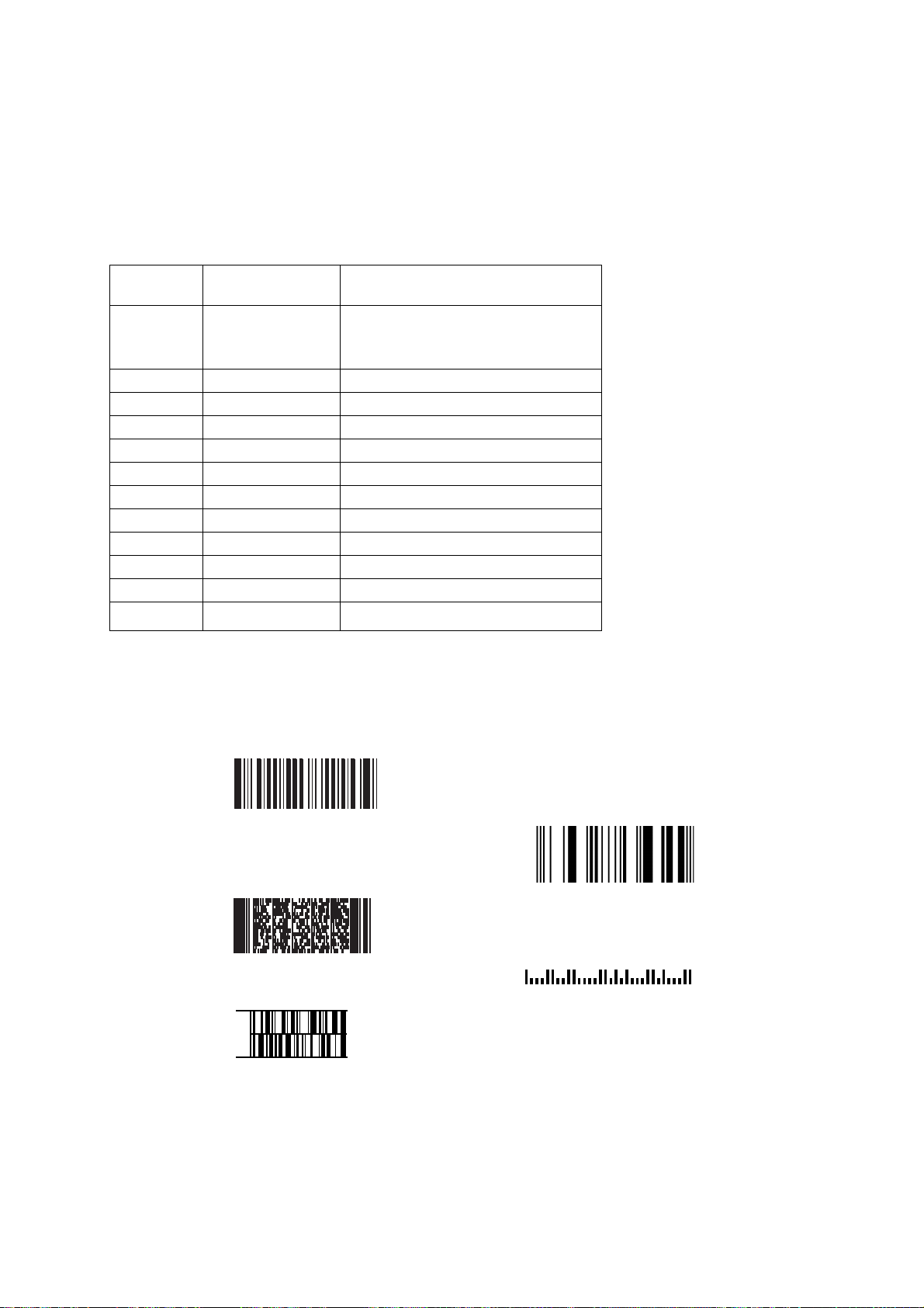
Appendix D: Sample Symbols
Sample Symbols
6543210
PDF417
Car Registration
Code 49
1234567890
RSS-14
(01)00123456789012
Postnet
Zip Code
46
Page 48

APPENDIX E : Programming Chart
a
d
c
g
l
t
Discard
e
h
r
Save
A
B
C
D
47
Page 49

0
1
2
3
5
6
7
8
9
Discard
4
Note: If you make an error while scanning the lette s or digits (before scanning Save), scan
r
Discard, scan the correct letters or digits, and Save.
48
 Loading...