

Page 1
Communication Protocol
©Baracoda TM – March. 2010
DualRunners
Data Capture
for Workforce
in Motion
Page 2

SUMMARY
SUMMARY
SUMMARYSUMMARY
Data Capture
for Workforce
in Motion
SUMMARY ................................................................... 2
REVISION HISTORY .......................................................... 4
1.
1.
1.1.
1.1. G
1.2. G
2.
2.
2.2.
2.1. B
2.1.1. C
2.2. S
2.2.1. E
2.2.2. D
2.3. H
2.3.1. C
2.3.2. S
2.3.3. U
2.3.4. M
2.3.5. C
2.3.6. A
2.4. D
2.4.1.
2.4.2. H
2.4.3. T
2.4.4. S
2.4.5. C
2.4.6. E
E
E
E
E
E
INTRODUCTION ........................................................ 5
ENERALITIES
ENERIC PACKET
COMMUNICATION PROTOCOL .............................................. 6
IDIRECTIONAL PACKETS
ONTROL MESSAGES
CANNER TO HOST MESSAGES
NCAPSULATION SCHEMA
ATA STRING SCHEMA
OST TO SCANNER MESSAGES
OMMUNICATION MESSAGES
CANNER MESSAGES
SER INTERFACE MESSAGES
ISCELLANEOUS MESSAGES
APTURE MESSAGES
DVANCED CAPTURE MESSAGES
ECODER COMMUNICATION PROTOCOL
FRAME FORMAT
EADER
YPE
IZE
OMMAND
XAMPLES
XAMPLE
XAMPLE
XAMPLE
XAMPLE
XAMPLE
1.1 – G
2.1 – S
2.2 – S
3.1 – M
4.1 – S
.......................................................... 5
........................................................ 5
................................................... 6
.............................................. 6
................................................ 7
........................................... 7
............................................ 7
................................................ 8
......................................... 8
............................................. 10
....................................... 12
........................................ 15
............................................. 19
..................................... 22
.......................................... 24
................................................ 24
..................................................... 24
....................................................... 25
....................................................... 25
.................................................... 25
................................................... 33
ETTING CONFIGURATION OF CODE 39 SYMBOLOGY
ETTING A CONFIGURATION OF CODABAR SYMBOLOGY
ETTING A CONFIGURATION OF ALL SYMBOLOGIES
ODIFYING A CONFIGURATION OF ALL SYMBOLOGIES
ENDING A SPECIAL COMMAND TO CODE39 SYMBOLOGY
. ................. 33
. ................ 34
. .................. 35
. ................ 35
. ............... 36
APPENDIX 1: BLUETOOTH PROTOCOL ........................................... 37
APPENDIX 2: RFID COMMUNICATION PROTOCOL .................................. 46
APPENDIX 3: RFID TAG DATA READ/WRITE EXAMPLES ............................ 54
(FOR BLACKBERRY, SYMBIAN & JAVA PLATFORMS) ............................... 54
1. INTRODUCTION .......................................................... 54
1.1 G
2.
2.
2.2.
ENERALITIES
MIFARE ULTRALIGHT TAGS ............................................. 55
........................................................... 54
DualRunners – Communication Protocol v1.3 - 2 -
Page 3

2.1 T
AG MEMORY STRUCTURE
2.2 R
EADING TAG DATA
2.3 W
RITING TAG DATA
Data Capture
for Workforce
in Motion
..................................................... 55
........................................................ 55
........................................................ 57
3. MIFARE 1K TAGS ........................................................ 59
3.1 T
AG MEMORY STRUCTURE
3.2 R
EADING TAG DATA
3.3 W
RITING TAG DATA
4.
4.
4.4.
4.1 T
4.2 R
4.3 W
5.
5.
5.5.
5.1 T
5.2 R
5.3 W
6.
6.
6.6.
6.1 T
6.2 R
6.3 W
MIFARE 4K TAGS ..................................................... 63
AG MEMORY STRUCTURE
EADING TAG DATA
RITING TAG DATA
TAG-IT HF-I PLUS INLAY TAGS ........................................ 68
AG MEMORY STRUCTURE
EADING TAG DATA
RITING TAG DATA
TAG-IT HF-I PLUS CHIP TAGS ......................................... 72
AG MEMORY STRUCTURE
EADING TAG DATA
RITING TAG DATA
..................................................... 59
........................................................ 59
........................................................ 61
..................................................... 63
........................................................ 63
........................................................ 66
..................................................... 68
........................................................ 68
........................................................ 70
..................................................... 72
........................................................ 72
........................................................ 74
7.
7.
7.7.
7.1 T
7.2 R
7.3 W
8.
8.
8.8.
8.1 T
8.2 R
8.3 W
I-CODE SLI TAGS .................................................... 76
AG MEMORY STRUCTURE
EADING TAG DATA
RITING TAG DATA
I-CODE SLI-S TAGS .................................................. 80
AG MEMORY STRUCTURE
EADING TAG DATA
RITING TAG DATA
..................................................... 76
........................................................ 76
........................................................ 78
..................................................... 80
........................................................ 80
........................................................ 82
DualRunners – Communication Protocol v1.3 - 3 -
Page 4

Revision History
Revision History
Revision HistoryRevision History
Changes to the original manual are listed below.
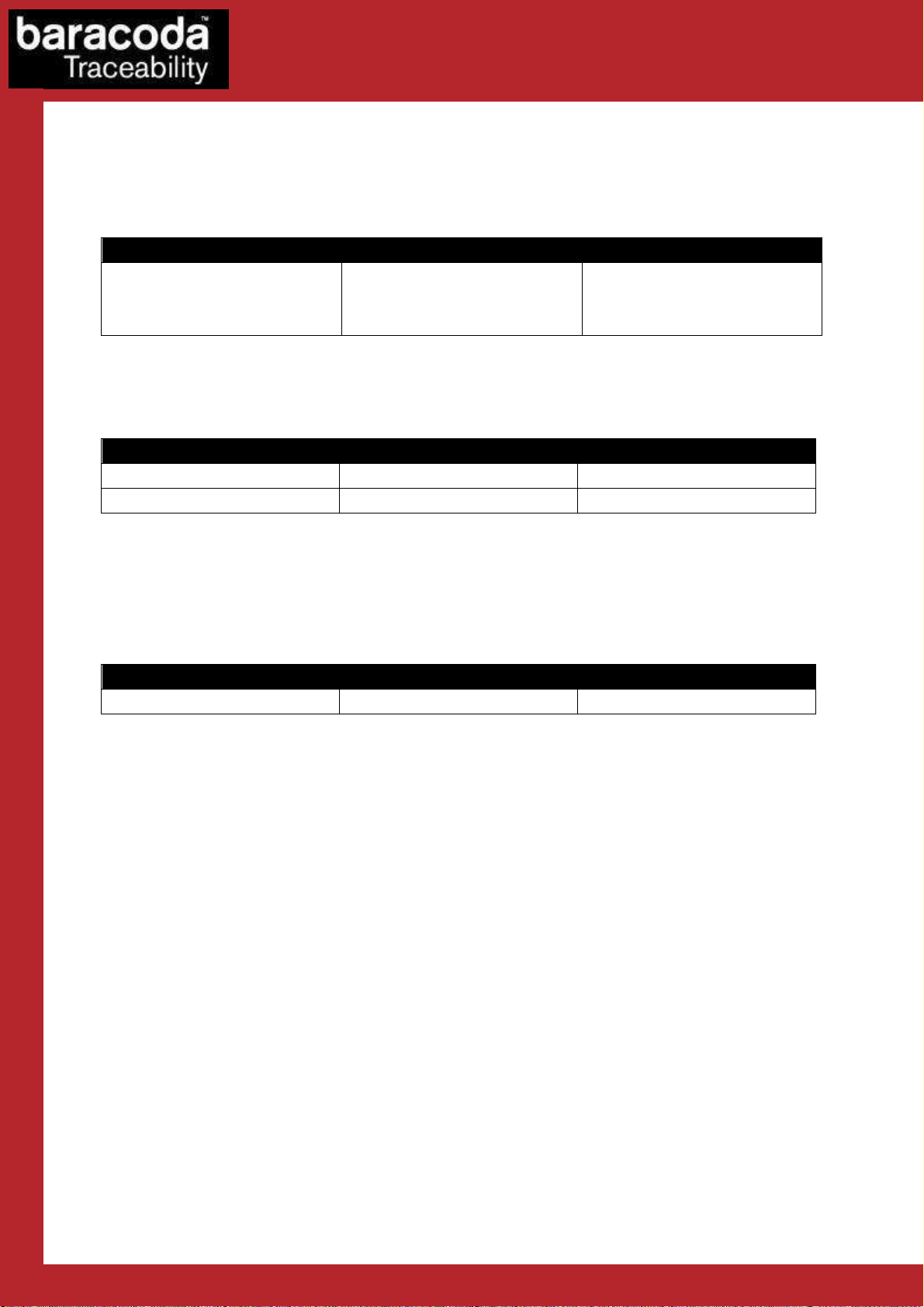
Document Date Description
Data Capture
for Workforce
in Motion
1.0 20 March 09
1.1 27 march 09 Add comments on 0xDA command
1.2 18 sept. 09 Add Appendix 3 “RFID tag data read/write examples’
1.3 15 March. 10
Initial release
Changed 2.2.1 : add 0x36-0x37 cmd
Add 2.3.6 “Advanced Capture messages”
DualRunners – Communication Protocol v1.3 - 4 -
Page 5

Data Capture
Code ID
Length
Payload
1
Byte
2 Bytes
N Bytes
for Workforce
1.
1.
1.1.
DualRunners is a wireless data capture product.
This document is detailing the protocol of communication between the Baracoda scanner and its
foreign environment through Radio Frequency link (ie: Bluetooth).
Wireless communication is based on the Bluetooth protocol, thanks to the embedded Baracoda
Equinox Bluetooth Stack.
Data capture capabilities are :
The messages described in this document can be:
Introduction
1.1.
1.1. Generalities
1.1.1.1.
- Barcode reading capabilities are enabled thanks to a CMOS technology (1D & 2D) or laser
(1D).
- HF Tag reading / encoding capabilities are enabled thanks to a RFID antenna & decoder.
- Host to scanner messages: the packet is sent only by the host to the scanner
- Scanner to host messages: the packet is sent only by the scanner to the host
- Bidirectional messages: the packet format is the same whether it is sent by the host or
the scanner
Generalities
GeneralitiesGeneralities
http://www.baracoda.com
in Motion
1.2.
1.2. Generic packet
1.2.1.2.
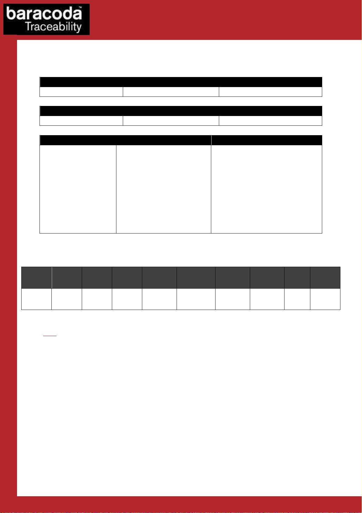
All the frames described in this document are formatted as shown:
- 1 byte for code ID
Bits 7:5 is the logical device
Bits 4:1 is the command
Bit 0: when set, the message must be acknowledged
- 2 bytes for the size of the payload (big-endian), including the sequence number byte which is
considered as part of the payload
- Payload (including 1 byte for sequence number when applicable).
The response will have the same code ID as the command.
Generic packet
Generic packetGeneric packet
DualRunners – Communication Protocol v1.3 - 5 -
Page 6
Data Capture
Code ID
Descriptio
n Frame
0x01
Legacy
0x01 0x01 0x01
Code ID
Description
Frame
0x06
ACK 0x06 0x01 0xYY
0x15
NACK
0x15
0x01 0xYY
Code ID
Description
Frame
0x16
SYN 0x16 0x01 0xYY
for Workforce
2.
2.
2.2.
Communication protocol
2.1.
2.1. Bidirectional
2.1.2.1.
Bidirectional packets
Bidirectional Bidirectional
packets
packetspackets
2.1.1. Control messages
2.1.1.1. Specific packets
Or
0x01 0x02 0x01
These two (2) sequences will be recognized and purged for backward compatibility with older
Baracoda products.
2.1.1.2. Acknowledgment packets
in Motion
These messages acknowledge the reception of a valid message with the expected sequence number
0xYY, before processing it.
For captured data from the scanner, ACK and NAK have the same meaning but will trigger a different
event on the scanner.
2.1.1.3. Synchronization packet
This message acknowledges the reception of a message to acknowledge with an unexpected
sequence number. 0xYY is the expected sequence number.
The device will resynchronize its remote sequence number when receiving this message.
DualRunners – Communication Protocol v1.3 - 6 -
Page 7
Code ID
Description
Payload
0x32
–
0x33
Barcode dat a
DATA
string
Code ID
Description
Payload
0x34
–
0x35
RFID
TagID
data
DATA
string
Code ID
Description
Payload
0x36-
0x37
Image(o r Si g nature)
data
n bytes :
2.2.
2.2. Scanner to hos
2.2.2.2.
Scanner to hostttt messages
Scanner to hosScanner to hos
2.2.1. Encapsulation schema
messages
messagesmessages
1st byte : packet type flag
- 0 = start : fragmented packet
- 1 = start: non fragmented
- 2 = continued packet
- 3 = last packet (End Of Body)
(n-1) bytes : packet data
remark : packet max size = 3000 bytes
Data Capture
for Workforce
in Motion
packet
2.2.2. Data string schema
Symbology
/Protocol ***
Prefix
AIM/Protocol**
Identifier
Nature
of data*
1 byte
Timestamp Data Prefix
12 bytes 0-32 bytes 0-32 bytes 0-4 bytes 0, 2 or 3 bytes - 0-4 bytes
Capture
Prefix
Nota :
* Nature Of Data byte is available only for DualRunners scanner (to identify if data is RFID TagID or
Barcode), by default this field is disabled. If enabled, Nature of data value is: 0x30 for Barcode and
0x31 for RFID TagID.
** These fields can be Symbology AIM if captured data is Barcode and RFID Protocol identifier if
captured data is RFID TagID.
*** These fields can be Symbology prefix/suffix if captured data is Barcode and RFID Protocol
prefix/suffix if captured data is RFID TagID.
Barcode /
RFID TagID
data
Symbology
/Protocol***
suffix
Capture
suffix
0-32
bytes
Data suffix
0-32 bytes
DualRunners – Communication Protocol v1.3 - 7 -
Page 8
Code ID
0x40
-
0x41
Description
Get Comm un i ca t ion Desc r i pt or
Payload
None
Response
2 bytes:
Code ID
0x42
-
0x43
Description
Get Retr a ns m i ssion Pa r a me t ers
Payload
None
Response
2 bytes:
Code ID
0x44
-
0x45
Description
Set Ret r a ns m ission P a ra m e ters
Payload
2 bytes:
Response
1 byte:
Code ID
0x46
-
0x47
Description
Get Ca p t u re F ra m e Fo rm a t
Payload
None
Response
1 byte
Code ID
0x48
-
0x49
Description
Set Capt u re Fr am e Format
Payload
1 byte
Response
1 byte:
2.3.
2.3. Host to
2.3.2.3.
Host to scanner
Host to Host to
2.3.1. Communication messages
{Wireless link: (Bit 0: Bluetooth)}
{Wired link: (Bit 0: Serial Dock)}
{Max number of retransmission, 1 to 0xFE, 0xFF = infinity}
{Delay between transmission, 1 to 0xFF, in tenth of seconds}
scanner messages
scannerscanner
messages
messagesmessages
Data Capture
for Workforce
in Motion
{Max number of retransmissions, 1 to 0xFE, 0xFF = infinity}
{Delay between transmissions, 1 to 0xFF, in tenth of seconds}
{(Bit 0: Success)}
{0 = Baracoda, 1 = Baracoda + ACK, 2 = Raw}
{0 = Baracoda, 1 = Baracoda + ACK, 2 = Raw}
{Bit0: Success}
DualRunners – Communication Protocol v1.3 - 8 -
Page 9
Data Capture
Code ID
0x50
-
0x51
Description
Lock/Unl o c k Data c a pt ur e m odule
(ie : S can e ng i n e, RFIDde co d e r board)
Payload
1 byte :
Response
1 byte :
{Bit 0 : Success}
Code ID
0x52
-
0x53
Description
Disable B a rc ode Prog r am m in g Functional i ty
Payload
1 byte :
Response
1 byte : {Bit 0 : Success}
Code ID
0x56
-
0x57
Description
Get/Set I n
charge be ha v i or
Payload
Get : None
Response
Get : 1 byte :
Remarks
When scanner in charge, the shutdown timers can be modified
Code ID
0x5A
-
0x5B
Description
Get/Set m ast er mode
Payload
Get : None
Response
Get : 1 byte :
Code ID
0x5E
-
0x5F
Description
Bluetoot h Command s
Payload
{Code ID} “Parameters”
Response
If the device responds: {Code ID} “Response”
for Workforce
{0 = Unlock, 1 = Lock}
{1 = Disable barcode programming functionality,
0 = Enable}
in Motion
Set : 1 byte :
{shutdown timeout (0 = leave current timeouts (default), 255 = infinity)}
{shutdown timeout (0 = leave current timeouts (default), 255 = infinity)}
Set : 1 byte :
{Bit 0 : Success}
Set : 1-2 byte(s) :
{1 : enable, 0 : disable}
[OPTIONAL]{1 : disconnect the scanner if connected}
{1 : enabled
0 : disabled}
Set : 1 byte :
{Bit 0 : Success}
Else: {0}
Bluetooth specific commands from the Platform2 Bluetooth communication protocol are to be
framed within the payload of this message.
DualRunners – Communication Protocol v1.3 - 9 -
Page 10
Code ID
0x60
-
0x61
Description
Get Sca n n er S t at us
Payload
None
Response
2 bytes:
Code ID
0x62
-
0x63
Description
Get Ope r a t ing Mode
Payload
None
Response
1 byte:
Remarks
“limited” means barcode buffer = 0 when in real time, no data
loss mode and
Code ID
0x64
-
0x65
Description
Set Oper a ti n g Mode
Payload
1 byte:
Response
1 byte:
Remarks
Batch mode is not available for D
-
Fly scanner
Code ID
0x66
-
0x67
Description
Get Shut d ow n T i mers
Payload
None
Response
2 bytes:
Code ID
0x68
-
0x69
Description
Set Shut d ow n T im ers
Payload
2 bytes:
2.3.2. Scanner messages
{(Bit 7: Upgrading) (Bit 1: Docked) (Bit 0: Charging)}
{Battery level, 0 to 100}
{Bit 0 = 0:real time, Bit 0 = 1: batch}
{(Bit 7: limited)}
Data Capture
for Workforce
in Motion
disconnected
{Bit 0 = 0: real time, Bit 0 = 1: batch}
If real time mode is set :
{(Bit 7: limited)(Bit 6: ACK beep) (Bit 5: no ACK beep)}
NOTE : the ACK beep enable / disable is only effective when Capture Frame Format is
“Baracoda + ACK”
{Bit 0: Success}
{Number of minutes before shutdown when connected, 1 to 0xFE,
0xFF = infinity}
{Number of minutes before shutdown when disconnected, 1 to 0xFE,
0xFF = infinity}
{Number of minutes before shutdown when connected, 1 to 0xFE,
0xFF = infinity}
DualRunners – Communication Protocol v1.3 - 10 -
Page 11
Data Capture
{Number of minutes before shutdown when disconnected, 1 to 0xFE,
Response
1 byte:
Code ID
0x6A
-
0x6B
Description
Get RTC t im e
Payload
None
Response
6 bytes:
Code ID
0x6C
-
0x6D
Description
Set RTC t i me
Payload
6 bytes:
Response
1 byte:
Code ID
0x74
-
0x75
Description
Restore de f au l ts se tt i ngs
Payload
None
Response
1 byte:
Remarks
External Flash memory is also erased
Code ID
0x76
-
0x77
Description
Get Pro d uc t Ve rsi on
Payload
None
Response
x bytes :
Code ID
0x78
-
0x79
Description
Get Swit c hi ng On Delay
Payload
None
Response
1
byte :
Code ID
0x7A
-
0x7B
Description
Set Switc hi ng On D e la y
Payload
1 byte :
Response
1 byte :
for Workforce
0xFF = infinity}
{Bit 0: Success}
{YY}{MM}{DD}{HH}{MM}{SS}
{YY}{MM}{DD}{HH}{MM}{SS}
in Motion
{Bit 0: Success}
{Bit 0: Success}
«Baracoda RRD…» for DualRunners product
{1 = 0 second, 2 = 1 second, 3 = 2 seconds}
{1 = 0 second, 2 = 1 second, 3 = 2 seconds}
{Bit 0 :Success}
DualRunners – Communication Protocol v1.3 - 11 -
Page 12
Code ID
0x80
-
0x81
Description
Get MMI D e sc ri pt or
Payload
None
Response
2 bytes:
Code ID
0x82
-
0x83
Description
Get MMI M ode
Payload
None
Response
1 byte:
Code ID
0x84
-
0x85
Description
Set MMI Mo d e
Payload
1 byte:
Response
1 byte: {(Bit 0: Success)}
Code ID
0x86
-
0x87
Description
Get MMI S ig na l (User i n t e rf ac e)
Payload
1 byte:
Response
(1 + 3n)
bytes:
Code ID
0x88
-
0x89
Description
Set MMI S i gn al
Payload
(2 + 3n) bytes
2.3.3. User Interface messages
LED 1 : left LED
LED 0 : right LED
{(Bit 6: Blue LED 1)
(Bit 5: Red LED 1)
(Bit 4: Green LED 1)
(Bit 2: Blue LED 0)
(Bit 1: Red LED 0)
(Bit 0: Green LED 0)}
{(Bit 0: Buzzer)}
Data Capture
for Workforce
in Motion
{(Bit 1: Buzzer Enabled) (Bit 0: LEDs enabled)}
{(Bit 1: Buzzer Enabled) (Bit 0: LEDs enabled)
(Bit 7 = 0:Buzzer config select, =1: Buzzer config deselect)(Bit 6 = 0:leds config select, =1:
leds config deselect)}
{Signal number, 0 - 3}
{Number of steps, 0 - 4}
For each step:
{(Bit 6: Blue LED 1) (Bit 5: Red LED 1) (Bit 4: Green LED 1) (Bit 2: Blue LED 0) (Bit 1: Red
LED 0) (Bit 0: Green LED 0)}
{Buzzer frequency, 0 – 0xFF * 50Hz = 0 – 12750Hz}
{Delay until next step, in tenth of seconds}
DualRunners – Communication Protocol v1.3 - 12 -
Page 13
Data Capture
{Signal number, 0
- 3}
Response
1 byte: {(Bit 0: Success)}
Code ID
0x8A
-
0x8B
Description
Play Sig n al
Payload
2 bytes:
Response
1 byte: {(Bit 0: Success)}
Code ID
0x8C
-
0x8D
Description
Stop Si g n al
Payload
1 byte:
Response
1 byte:
for Workforce
{Number of steps, 0 - 4}
For each step:
{(Bit 6: Blue LED 1) (Bit 5: Red LED 1) (Bit 4: Green LED 1) (Bit 2: Blue LED 0) (Bit 1: Red
LED 0) (Bit 0: Green LED 0)}
{Buzzer frequency, 0 – 0xFF * 50Hz = 0 – 12750Hz}
{Delay until next step, in tenth of seconds}
{Signal number, 0 - 3}
{Number of loops, 0 – 0xFE, 0xFF = infinity}
in Motion
{Signal number, 0 – 3}
{(Bit 0: Success)}
The list of MMI signals is:
IHM_SIGNAL_CAPTURE_READ : 0
IHM_SIGNAL_CAPTURE_ACK : 1
IHM_SIGNAL_CAPTURE_NAK : 2
IHM_SIGNAL_CAPTURE_LOST : 3
IHM_SIGNAL_USER_DEFINED : 13
DualRunners – Communication Protocol v1.3 - 13 -
Page 14

Data Capture
Code ID
0x92
-
0x93
Description
Get Beep s m od e
Payload
Response
1 byte:
Code ID
0x94
-
0x95
Description
Set Bee p s m ode
Payload
1 byte:
Response
1 byte:
for Workforce
{(Bit 0: Beep level 0=low, 1=high)
(Bit 1: Read beep)
(Bit 2: ACK beep)}
{(Bit 0: Beep level; 0=low, 1=high)
(Bit 1: Read beep)
(Bit 2: ACK beep)
(Bit 7 = 0: ACK beep config select, =1: ACK beep config deselect)
(Bit 6 = 0: Read beep config select, =1: Read beep config deselect)
(Bit 5 = 0: Beep level config select, =1: Beep level config deselect)}}
in Motion
{(Bit 0: Success)}
DualRunners – Communication Protocol v1.3 - 14 -
Page 15
Code ID
0xC2
-
0xC3
Description
Get/Set D at a Prefix
Payload
Get : None
Response
Get : 1
-
33 bytes:
Remarks
Configure value of ‘DataPrefix’
Code ID
0xC4
-
0xC5
Description
Get/Set D at a Suffix
Payload
Get : None
Response
Get : 1
-
33 bytes:
Remarks
Configure value of ‘Data
Suf
fix’
Code ID
0xC6
-
0xC7
Description
Get/Set D at a F ormat 2
Payload
Get :
None
Response
Get : 1 byte:
Remarks
Enable, disable the adding of ‘Data Prefix’ and ‘Data Suffix’
2.3.4. Miscellaneous messages
Set : 1-33 bytes:
{ DataPrefix length}
“DataPrefix String”
{ DataPrefix length}
“DataPrefix String”
Set : 1 byte:
{Success?}
Data Capture
for Workforce
in Motion
Set : 1-33 bytes:
{ DataSuffix length}
“DataSuffix String”
{ DataSuffix length}
“DataSuffix String”
Set : 1 byte:
{Success?}
Set : 1 byte:
{(Bit 5 = 0: DataPrefix config select, =1: DataPrefix config deselect)
(Bit 4 = 0: DataSuffix config select, =1: DataSuffix config deselect)
(Bit 1: DataPrefix)
(Bit 0: DataSuffix)
{(Bit 1: DataPrefix)
(Bit 0: DataSuffix)}
Set : 1 byte:
{(Bit 0:Success)}
DualRunners – Communication Protocol v1.3 - 15 -
Page 16
Data Capture
Code ID
0xC8
-
0xC9
Description
Get / Se t
Captured da ta
(barco d e or T agID)
length
Payload
Get : None
Response
Get : 2 bytes
Code ID
0xCA
-
0xCB
Description
Get and e ra s e st or ed
Captured da t a
with n o d a t a loss m o d e
Payload
None
Response
1 byte
Code ID
0xCC
-
0xCD
Description
Res
et mode s
Payload
None = restore defaults, keep link keys, reboot scanner
Response
1 byte
Code ID
0xCE
-
0xCF
Description
Batch u p l o ad comm a n ds
Payload
{Code ID} “Parameters” (cf. below)
Response
{Code ID} “Response”
Code ID
0
Description
Launch upload process (typically used only for the upload barcode)
Payload
1 byte:
Response
1 byte:
Code ID
1
Description
Ready to start upload (Scanner to host message)
Payload
3 bytes :
for Workforce
Set : 2 bytes
{authorized barcode length. 0 = disabled}
{authorized barcode length. 0 = disabled}
Set : 1 byte
{(Bit 0:Success)}
{(Bit 0:Success)}
in Motion
1byte :
0 = restore defaults, keep link keys, reboot scanner
1 = switch off scanner (no restoring defaults)
2 = reboot scanner (no restoring defaults)
{(Bit 0:Success)}
The UPLOAD Code IDs are:
{0 mandatory}
{Bit 0: Success}
{0 mandatory}
{ number of elements to be uploaded MSB }
DualRunners – Communication Protocol v1.3 - 16 -
Page 17
Data Capture
{ number of elements to be uploaded LSB }
Response
None
Code ID
2
Description
Start uploading barcodes
Payload
1 byte:
Response
1 byte:
Code
ID 3
Description
RESERVED
Payload
N/A
Response
N/A
Code ID
4
Description
Set upload status and end process
Payload
2 bytes :
Response
1 byte:
Code ID
0xD0
-
0xD1
Description
Get Seri a l N um be r
Payload
Get: None
Response
Get : 2
-
15 bytes:
Code ID
0xD2
-
0xD3
Description
Get/Set A nt i duplicat e s c an s
Payload
Get : None
Response
Get : 1 byte
for Workforce
{0 mandatory}
{Bit 0: Success}
in Motion
{0 mandatory}
{1 : upload successful, data can be erased from the scanner
0 : upload failed, do not erase data}
{Bit 0: Success}
{ Serial Number string length }
[S/N (1-14 bytes)]
Set : 1 byte
{0 = disabled
1 = no consecutive duplicate scans + error signal
2 = no consecutive duplicate scans + no decoding}
{0 = disabled
1 = no consecutive duplicate scans + error signal
2 = no consecutive duplicate scans + no decoding }
Set : 1 byte
{(Bit 0:Success)}
DualRunners – Communication Protocol v1.3 - 17 -
Page 18
Data Capture
Comments
The comparison will be made over the 32 first characters of the barcodes only.
Code ID
0xD4
-
0xD5
Description
Restore l a st batch
Payload
None
Response
1 byte:
Comments
This is only available if no new
data capture
has been made.
Code ID
0xD8
-
0xD9
Description
Enable r e m ote trig g e r
Payload
None : use default 5s timeout
Response
1 byte
Code ID
0xDA
-
0xDB
(DualRunner Specific)
Description
Set/Get D ua l Runner
s Mode
Payload
None to get mode
Response
If Get, 2 bytes Mode, Status (1 if success, 0 if failed)
Remarks
Nature of Data Byte is equal to :
-
Code ID
0xDE
-
0xDF
Description
RFID co m m ands
Payload
{Code ID} “Parameters
”
Response
{Code ID} “Response”
for Workforce
or 1 byte (optional):
{1 = upload data after retrieving}
{(Bit 0:Success)}
in Motion
1 byte : {timeout (s)}
{(Bit 0:Success)}
1 Byte to set mode
Bits 6-0 : 00 switch DualRunners to Both data capture (Barcode and RFID TagID)
01 switch DualRunners to Barcode reader (RFID TagID can’t be read)
02 switch DualRunners to TagID reader (Barcode can’t be read)
Bit 7: 0 Desactivate Nature Of Data byte (Default value)
1Activate Nature Of Data byte
If Set, 1 byte (1 if success, 0 if failed)
- 0x30 if data is a barcode
0x31 if data is a RFID HF TagID
RFID specific commands from the Platform2 RFID communication protocol are to be framed within
the payload of this message (cf APPENDIX)
DualRunners – Communication Protocol v1.3 - 18 -
Page 19
Code ID
0xE0
-
0xE1
Description
Get
Capture
Versio n
Payload
None
Response
“Capture Version String” or {0} if not applicable
Remarks
Capture Version Strings can be :
Code ID
0xE2
-
0xE3
Description
Get Mod e
Payloa
d None
Response
1 byte:
Code ID
0xE4
-
0xE5
Description
Set Mode
Payload
1 byte OR
Response
1 byte:
Code ID
0xE6
-
0xE7
Description
Get Dat a For mat
Payload
None
Response
1 byte:
Code ID
0xE8
-
0xE9
Description
Set Data F ormat
Payload
1 byte:
Response
1 byte:
2.3.5. Capture messages
"DUAL_1D" the scanner is a DualRunners with a 1D non decoded scan engine + an
RFID external daughter board
"DUAL_2D" the scanner is a DualRunners with a 2D decoded HHP scan engine + an
RFID external daughter board
Data Capture
for Workforce
in Motion
{0 = trigger, 1 = smart autoscan, 2 = disabled, 3= autoscan, 4=aiming trigger scan}
2 bytes if aiming trigger scan mode
{0 = trigger, 1 = smart autoscan, 2 = disabled, 3= autoscan, 4=aiming trigger scan}
{aiming trigger scan mode timeout value in second}
{(Bit 0: Success)}
{(Bit 2:Timestamp)
(Bit 1: Capture Prefix)
(Bit 0: Capture Suffix)}
{(Bit 7 = 0: Timestamp config select, =1: Timestamp config deselect)
(Bit 6 = 0: Capture Prefix config select, =1: Capture Prefix config deselect)
(Bit 5 = 0: Capture Suffix config select, =1: Capture Suffix config deselect)
(Bit 2:Timestamp)
(Bit 1: Capture Prefix)
(Bit 0: Capture Suffix) }
DualRunners – Communication Protocol v1.3 - 19 -
Page 20
Data Capture
{(Bit 0:Succe
ss)}
Code ID
0xEA
-
0xEB
Description
Get
Capture
Prefix
Payload
None
Response
1-
33 bytes:
Code ID
0xEC
-
0xED
Description
Set
Capture
Prefix
Payload
1-
33 bytes:
Response
1 byte:
Code ID
0xEE
-
0xEF
Description
Get
Capture
Suffix
Payload
None
Response
1-
33 bytes:
Code ID
0xF0
-
0xF1
Description
Set
Capture
Suffix
Payload
1-
33 bytes:
Response
1 byte:
Code ID
0xF4
-
0xF5
Description
Set Tim e s ta m p
Payload
6 bytes:
Response
1 byte:
Code ID
0xF6
-
0xF7
Description
Set AI M
Barcode
Symbol o g y I de nt if i er trans m is si o n
Payload
1 byte:
Response
1 byte:
for Workforce
{ Capture Prefix length}
“Capture Prefix String”
{ Capture Prefix length}
“Capture Prefix String”
in Motion
{(Bit 0:Success)}
{ Capture Suffix length}
“Capture Suffix String”
{ Capture Suffix length}
“Capture Suffix String”
{(Bit 0:Success)}
{YY}{MM}{DD}{HH}{MM}{SS}
{Bit 0: Success}
{0 : disabled, 1 : enabled}
DualRunners – Communication Protocol v1.3 - 20 -
Page 21
Data Capture
{Bit 0: Success}
Code ID
0xF8
-
0xF9
Description
Get stor e d
capt ure d data
count
Payload
None
Response
2 bytes:
Code ID
0xFC
-
0xFD
Description
Erase st o re d c aptured d a t a
(ie: b a r co de s o r T agID)
Payload
None
Response
1 byte:
Code ID
0xFE
-
0xFF
Description
Barcode
decoder C om ma nd s
Payload
{header} {type} {size} “Parameters”
Response
If the device responds:
Remarks
Only available if Scan engine is 1D version
for Workforce
{Stored captured data (barcodes or TagID) count [15:8]}
{Stored captured data (barcodes or TagID) count [7:0]}
{(Bit 0:Success)}
in Motion
{Code ID}{length}{header}{type} {response size} “Response”
Else: {0}
Barcode decoder specific commands from the Platform2 Decoder communication protocol are to be
framed within the payload of this message.
DualRunners – Communication Protocol v1.3 - 21 -
Page 22

Code
ID 0xA2
-0xA3
Description
Intellige n t Image P a r ameters
(for app l i cations s u c h as sign a t ur e c ap t ur e)
Payload
17 bytes:
Bytes
0 – 1 2 – 3 4 – 7 8 - 11
12 –
14 15 16
parameters
Width
Height
X
Aspect
Resolution
Bits /
Image
Response
1 byte:
2.3.6. Advanced capture messages
Data Capture
for Workforce
in Motion
13
offset Y offset
Width is the width of signature capture area (LSB First). (in inch)
Height is the hight of signature capture area (LSB First). (in inch)
X offset : Horizontal Bar Code Offset, The horizontal ratio offset of the center of the
signature capture area, in multiples of the minimum bar width (LSB First). (in inch)
Y offset: Vertical Bar Code Offset, The vertical offset of the center of the signature
capture area, in multiples of the minimum bar width. Negative numbers indicate that the
signature capture is above the bar code, and positive numbers indicate that the area is
below the bar code (LSB First). (in inch)
Aspect Ratio: Bar Code Aspect Ratio, The ratio of the bar code height to the narrow
element width (LSB First).
Resolution: Resolution of Signature Capture Area, The number of pixels that the scanner
outputs per each minimum bar width. The higher the value for Resolution, the higher the
quality of the image, but also the larger the file size.
Bits/Pixel: Indicates the number of bits per pixel in the transmitted image (possible
values : 1 or 8)
Image Format:
0: KIM format
1: TIFF binary
2: TIFF binary group 4, compressed
3: TIFF grayscale
4: Uncompressed Binary
5: Uncompressed grayscale
6: JPEG image (default)
7: Outlined image
8: BMP format
Ratio
Pixel
format
{Bit 0: 1 if Success}
DualRunners – Communication Protocol v1.3 - 22 -
Page 23
Data Capture
Code ID
0xA4
-
0xA5
Description
Intellige n t Image R e fe re nc e
Payload
Byte 1 : reference barcode length
Remarks
Reference barcode can of one of these symbologies: PDF417, Code 39, Code 128, Aztec,
Response
1 byte:
Code ID
0xA6
-0xA7
Description
Intellige n t Image E n abled
Payload
1 byte:
Response
1 byte:
for Workforce
Byte 2 to …. Up to byte 21: reference barcode data
Reference barcode data are the content of barcode serving as reference to the signature
area. When a configured reader read a barcode that much witch this reference barcode,
its try to get a signature/image defined by its area (see 0xA2 command)
Codabar, and Interleaved 2 of 5
{(Bit 0: 1 if Success)}
in Motion
1 enabled
0 disabled
Enable or disable the intelligent image capture capability
{(Bit 0: 1 if Success)}
Special case:
As the pictures can be several Kilo bytes of data, Baracoda has implemented a specific transmission
protocol to get image in the best conditions.
We assume that Reader is correctly configured.
1 Scan reference Barcode
a. Switch OFF beam indicates reference barcode read.
b. Scanner checks if it’s a reference barcode.
i. If yes, barcode is not sent to the host
ii. If no, barcode is sent to the host (normal behavior) and go to step 3.
c. Scanner send INCOMING_IMAGE event (value is 0x40 00 00) and set User interface
(depending on operating mode):
i. Left Led orange fix
ii. Buzzer ticks
d. Wait for ACK/NACK about INCOMING_IMAGE event (value is 0xA0 00 01 XX) or
TimeOut (Capture Trigger TimeOut (5 second default)).
i. XX = 1 => ACK: host is ready to receive image
ii. XX != 1 => NACK: host not able to receive image
e. Release Left Led and stop buzzer (depending on operating mode)
i. If ACK received : start processing of image
ii. If NACK or TimeOut, stop capture and play Capture Lost signal
2 Scanner returns to normal operating mode (trigger, autoscann …)
DualRunners – Communication Protocol v1.3 - 23 -
Page 24
1Byte
1Byte
1Byte
Header
Selected Symbology
A SELECT ALL
B Code 93
C Code 128 / EAN 128
D EAN 13 / UPC
A
E Code 39
F Codabar
G Interleaved 2 of 5
H Standard 2 of 5
(industrial 2 of 5)
I Matrix 2 of 5 (symbology disabled)
J Code 11
K MSI
L UPC E
M EAN 8
N RSS14 (not available on RoadRunners product)
O RSSLTD
(not available on RoadRunners product)
2.4.
2.4. Decoder Communication
2.4.2.4.
Decoder Communication Protocol
Decoder CommunicationDecoder Communication
Protocol
ProtocolProtocol
2.4.1. frame format
Header Type Size (Bytes) Command
2.4.2. Header
The Header field defines the type of symbology to select; it is 1 byte long (ACSII code):
Data Capture
for Workforce
in Motion
Note: The "A" header (SELECT ALL) allows the selection of all the symbologies available. Thus, only general commands will be allowed.
DualRunners – Communication Protocol v1.3 - 24 -
Page 25

Type
Description
D
E
2.4.3. Type
The Type field defines the type of command to be sent to the reader, it is 1 byte long.
Data Capture
for Workforce
in Motion
A
B
C
(*): This Type of command is not available with "A" header.
(1): This command concerns the whole set of options available for one symbology. Its description will
be given in the section "Command field".
(2): This type is used for commands requiring non Boolean information. Their length will be at least 2
bytes, the first one defining the type of command, the other(s) being the parameter(s) to use. More
details will be given in the section "Command field".
All the commands will answer “0” if the frame is wrong.
Commands with type B, C, D or E will answer “1” as an acknowledgment of good reception of the
command.
The “Get config” command (type A) will answer 2 or 4 bytes : the two firsts follow the format
described below (see “set config” command field). The third and fourth bytes correspond to
minimum and maximum lengths if the selected symbology supports this option.
Get config: asks the reader to give the configuration options for the selected symbology. (1) (*)
Set config : sets an options configuration for the selected symbology. (1)
Set Default: sets the default options configuration for the selected symbology(ies).
Usual Command.
Special Command (with parameters). (2)
2.4.4. Size
This field specifies the length (bytes) of the following field (commands). It will be set to "0" if the type
was "A" (Get Config) or "C" (Set Defaults),
2.4.5. Command
This field contains the commands, its length must be the one specified in the Size field.
There are five types of commands:
2.4.5.1.
2.4.5.1. Set Config (
2.4.5.1.2.4.5.1.
This command is made up of 1 or 2 bytes. The first one contains information for configuration of
general options (common to all the symbologies). The second one, optional, relates to specific
options to each symbology.
DualRunners – Communication Protocol v1.3 - 25 -
Set Config (Type
Set Config (Set Config (
Type """"BBBB")
Type Type
")
")")
Page 26

Data Capture
Bit Option
LSB 0 Enable/Disable
Symbology
1
Enable/Disable Min. length (1)
2
Enable/Disable Checksum calculation (2)
3
Enable/Disable Checksum transmission
4
Enable/Disable M
ax
. length (
3)
5
Enable/Disable
symbology prefix (4)
6
Enable/Disable
symbology suffix (4)
MSB
7
FREE
CODE 93 (Header "B")
Bit Option
LSB 0 FREE
1
FREE
2
FREE
3
FREE
4
FREE
5
FREE
6
FREE
MSB
7
FREE
for Workforce
For a Set Config (type "B") with a SELECT ALL (header "A"), the command sent can only be 1 byte
long.
Note: A high level bit ("1") corresponds to an Enable, a "0" bit means Disable.
BYTE 1 (general options):
The format of this byte is the same for all symbologies.
in Motion
(1): If Min. length is enabled without having been set with the special command, the default minimal
length will be 6 characters for all symbologies.
(2): This option will not have any effect on symbologies that require a checksum (EAN/UPC, code93,
Code128, RSS). Concerning the symbologies that allow two check digits (MSI, code11), the first check
digit is obligatory. Thus, this option will affect the calculation/non calculation of the second check
digit.
(3): If Max. length is enabled without having been set with the special command, the default minimal
length will be 32 characters for all symbologies.
(4): if the prefix/suffix is enabled without having been defined at least once (cf. special command),
there will be no effect.
BYTE 2 (specific options):
Each symbology will have a different configuration of this byte, depending on the specific options
available on each.
DualRunners – Communication Protocol v1.3 - 26 -
Page 27

Data Capture
CODE 128 / EAN 128 (Header "C")
Bit Option
LSB 0 GS transmit (EAN128)
1
AIM Symb ID transmit (EAN128)
2
FREE
3
FREE
4
FREE
5
FREE
6
FREE
MSB
7
FREE
EAN 13 / UPC
-
A (Header "D")
Bit Option
LSB 0 Number System
transmitted (UPC A)
1
Enable/disable ISBN and ISSN
2
ISSN hyphen transmission
3
ISSN price code transmission
4
UPC-A, transmitted as EAN 13
5
Add-on Digits required/not required
6
Enable/disable Add
-
on 2
MSB
7
Enable/disable Add
-
on 5
CODE 39 (Header "E")
Bit Option
LSB 0 Enable/Disable start
-
stop transmission
1
Enable/Disable Full ACSII Mode
2
Enable/Disable "*" as start
-
stop character
3
Enable/Disable "$" as start
-
stop character
4
FREE
5
FREE
6
FREE
MSB
7
FREE
CODABAR (Header "F")
Bit Option
LSB 0 Enable/Disable start
-
stop transmission
1
FREE
2
FREE
3
FREE
4
FREE
5
FREE
6
FREE
MSB
7
FREE
for Workforce
in Motion
DualRunners – Communication Protocol v1.3 - 27 -
Page 28

Data Capture
INTERLEAVED 2 OF 5 (Header "G")
Bit Option
LSB 0 FREE
1
FREE
2
FREE
3
FREE
4
FREE
5
FREE
6
FREE
MSB
7
FREE
STANDARD 2 OF 5 (Header "H")
Bit Option
LSB 0 FREE
1
FREE
2
FREE
3
FREE
4
FREE
5
FREE
6
FREE
MSB
7
FREE
MATRIX 2 OF 5 (Header "I")
Bit Option
LSB 0 FREE
1
FREE
2
FREE
3
FREE
4
FREE
5
FREE
6
FREE
MSB
7
FREE
CODE 11 (Header "J")
Bit Option
LSB 0 FREE
1
FREE
2
FREE
3
FREE
4
FREE
5
FREE
6
FREE
MSB
7
FREE
for Workforce
in Motion
DualRunners – Communication Protocol v1.3 - 28 -
Page 29

Data Capture
MSI (Header "K")
Bit Option
LSB 0 FREE
1
FREE
2
FREE
3
FREE
4
FREE
5
FREE
6
FREE
MSB
7
FREE
UPC-E (Header "
L")
Bit Option
LSB 0 Number System transmitted
1 -
2 -
3 -
4
FREE
5
UPC-E transmitted as UPC
-A
6 -
MSB
7
FREE
EAN 8 (Header "
M")
Bit Option
LSB 0 FREE
1 -
2 -
3 -
4
EAN 8
transmitted as EAN 13
5
FREE
6 -
MSB
7
FREE
RSS 14
(Header "
N")
Bit Option
LSB 0 LINKAGE FLAG PRINT
1
APPLICATION ID PRINT
2
FREE
3
FREE
4
FREE
5
FREE
6
FREE
for Workforce
in Motion
DualRunners – Communication Protocol v1.3 - 29 -
Page 30

Data Capture
MSB
7
FREE
RSS Limited
(Header "
O")
Bit Option
LSB 0 LINKAGE FLAG PRINT
1
APPLICATION ID PRINT
2
FREE
3
FREE
4
FREE
5
FREE
6
FREE
MSB
7
FREE
for Workforce
in Motion
2.4.5.2.
2.4.5.2. Get config
2.4.5.2.2.4.5.2.
This command allows to retrieve the whole configuration of a given symbology. The response to it is
made of 2 or 4 bytes:
The two first bytes are the ones described in the above section (set config).
The two following are given only if the length of the barcode is variable with the selected symbology.
These bytes are the min and max length of the barcode.
For some settings (e.g. prefix/suffix…), the “special commands” type should be used (see below for
details).
2.4.5.3.
2.4.5.3. Usual Commands (Type
2.4.5.3.2.4.5.3.
The method described above (set config) allows a fast and effective setting of a whole set of
configurations for a given symbology. It exclusively allows a simultaneous configuration of all the
options available for a given symbology.
The usual commands are designed to palliate this effect. It is possible, with this type of commands, to
modify a limited number of options in a configuration.
A command is one byte long and orders an enabling or a disabling of an option. Several commands
can be sent in the same frame by simply specifying the number in the Size field.
The commands table is unique. All the symbologies will thus understand this same table. However,
since certain options are not available for some symbologies, the corresponding commands will be
quite simply ignored for these symbologies. This will allow the configuration of several symbologies
at the time by sending only one frame.
Get config((((Type
Get configGet config
Usual Commands (Type """"DDDD""""))))
Usual Commands (Type Usual Commands (Type
Type """"AAAA")
Type Type
")
")")
DualRunners – Communication Protocol v1.3 - 30 -
Page 31

Data Capture
COMMANDS TABLE
Ascii
A Enable Symbology
B Disable Symbology
C Disable
Min. length
D Enable Min. length (1)
E Enable Checksum calculation (2)
F Disable Checksum calculation (2)
G Enable Checksum transmission
H Disable Checksum transmission
I Enable start/stop characters transmission
J Disable start/stop characters transmission
K Start/stop accepted characters "*" only
L Start/stop accepted characters "$"
only
M start/stop accepted characters "*" and "$"
N Enable Code 39 full ASCII mode
O Disable Code 39 full ASCII mode
P Enable number system transmission
Q Disable number system transmission
R Disable prefix
S Enable
prefix
T Disable suffix
U Enable suffix
V Enable ISBN and ISSN
W Disable ISBN and ISSN
X UPC-A/EAN 8 transmitted as EAN 13
Y UPC-A/EAN 8 transmitted as UPC
-
A/EAN 8
Z UPC-E transmitted as UPC
-A
a UPC-E transmitted as UPC
-E
b Enable hyphen transmission for ISSN
c Dis
able hyphen transmission for ISSN
d Disable Max. length
e Enable Max. length (3)
f Enable all EAN/UPC symbologies
g Disable all EAN/UPC
symbologies
i Enable linkage flag transmission
j Dissable linkage flag transmission
k Enable application identifier transmission
l Dissable application identifier transmission
m Enable Group separator transmission (EAN128)
n Dissable Group separator transmission (EAN128)
for Workforce
in Motion
CODE COMMAND
RESPONDING HEADERS
All
All
A, B, C, E, F, G, H, J, K
A, B, C, E, F, G, H, J, K
E, F, G, H, J, K
E, F, G, H, J, K
C, D, E, F, G, H, J, K, L, M,N,O
C, D, E, F, G, H, J, K, L, M,N,O
E, F
E, F
E
E
E
E
E
D, L
D, L
All
All
All
All
D
D
D, M
D, M
L
L
D
D
A, B, C, E, F, G, H, J, K
A, B, C, E, F, G, H, J, K
D, L, M
D, L, M
N,O
N,O
N,O
N,O
C
C
DualRunners – Communication Protocol v1.3 - 31 -
Page 32

Data Capture
o Enable AIM symbology identifier transmission
p Disable AIM symbology identifier transmission
q Enable Price Code
transmission for ISSN
r Disable Price Code
transmission for ISSN
s Add-on
Digits not required but transmitted if read
t Add-on Digits required and transmitted
u Enable 2
-
digit Add
-
on
v Disable 2
-
digit Add
-on
w Enable 5
-
digit Add
-on
x disable 5
-
digit Add
-on
SPECIAL COMMANDS
ASCII
A DEFINE AND ENABLE MIN.
LENGTH
[MIN LENGTH]
-
B DEFINE AND ENABLE MAX. LENGTH
[MAX LENGTH]
-
C DEFINE AND ENABLE LENGTH FRAME
[MIN][MAX]
-
D DEFINE VOTING VALUE (*)
[VOTING]
-
E GET VOTING VALUE
-
[VOTING]
F DEFINE GS REPLACEMENT CHARACTER
[CHAR]
-
G GET GS REPLACEMENT
CHARACTER
-
[CHAR]
H DEFINE AND ENABLE PREFIX
[length]
« prefix
» -
I DEFINE AND ENABLE SUFFIX
[length]
«suffix»
-
J GET PREFIX
-
[length]
« prefix
»
K GET SUFFIX
-
[length]
«suffix»
L FREE
- -
… … … …
for Workforce
C
C
D
D
D
D
D
D
D
D
(1): The default minimal length is 6 characters for all symbologies.
(2): This option will not have any effect on symbologies requiring a checksum calculation (EAN/UPC, Code128).
Concerning the symbologies that allow two check digits (code93, code11), the first check digit is obligatory.
Thus, this option will affect the calculation/non calculation of the second check digit.
(3): The default maximal length is 32 characters for all symbologies.
in Motion
2.4.5.4.
2.4.5.4. Special
2.4.5.4.2.4.5.4.
Some commands require more than a Boolean digit and require one or more arguments.
Special commands will be used in this case (defined code "E" in type field). It is made of one byte
corresponding to the type of command. Then, depending on the type of command, a certain number
of parameters will be expected. Each of these will be 1 byte long.
This type of command allows the sending of multiple commands in one frame. The Size field must
then specify the total length, in bytes, of the command field.
CODE DESCRIPTION PARAMTER(S) RESPONSE
Special Commands
Special Special
Commands (Type "
CommandsCommands
(Type "EEEE")
(Type "(Type "
")
")")
(*): this command will only de effective with ‘A’ header. Otherwise, it will be ignored. Values
accepted for voting are: 2, 3, 4. this command is also unavailable with Pencil2 scanner.
DualRunners – Communication Protocol v1.3 - 32 -
Page 33

Data Capture
Header
Type
Size
Command
Header
Type
Size
Command
1st
byte :
$01 Bit Option
1 0 Symbology Enabled
0 1 Min.
length
Disable
d
0 2 Checksum calculation
Disable
d
0 3 Checksum transmission Disable
d
0 4 Max. length Disable
d
0 5 -
0 6 -
0 7 -
2nd
byte :
$05
Bit Option
1 0 start
-
stop transmission
Enabled
0 1 Full ACSII Mode
Disable
d
1 2 "*" as start
-
stop character
Enabled
0 3 "$" as start
-
stop character
Disable
d
0 4 -
0 5 -
0 6 -
0 7 -
for Workforce
in Motion
2.4.6. Examples
Here are some examples to illustrate each type of frame to be sent to the decoder and the possible
answer from the decoder.
2.4.6.1.
2.4.6.1. Get Config
2.4.6.1.2.4.6.1.
Get Config
Get ConfigGet Config
Example 1.1 – Getting configuration of Code 39 symbology.
Frame to be sent to the decoder:
‘E’ ‘A’ 0 -
The decoder answers the following frame:
‘E’ ‘A’ 4 $01 , $05, $06, $20
By reading this answer frame, we can check that the decoder has well understood the selected
symbology (header "E"). The command field contains the configuration itself:
3rd byte : Min length = 6
th
byte Max length = $20 = 32
4
DualRunners – Communication Protocol v1.3 - 33 -
Page 34

Data Capture
Header
Type
Size
Command
1st
byte :
$03
Bit Option
1 0 Symbology Enabled
1 1 Min.
length
Enabled (set to 6 as default)
0 2 Checksum calculation
Disable
d
0 3 Checksum transmission Disable
d
0 4 Max. length Disable
d
0 5 -
0 6 -
0 7 -
2nd
byte :
$01
Bit Option
1 0 start
-
stop transmission
Enabled
0 1 -
0 2 -
0 3 -
0 4 -
0 5 -
0 6 -
0 7 -
for Workforce
2.4.6.2.
2.4.6.2. S
2.4.6.2.2.4.6.2.
Set Config
et Config
SS
et Configet Config
in Motion
Example 2.1 – Setting a configuration of Codabar symbology.
Frame to be sent to the decoder:
‘F’ ‘B’ 2 $03 , $01
Reading this frame, the decoder understands:
The user wants to set a configuration (Type "B") for Codabar (Header "F"). the configuration will
contain general options and others specific to cadabar (Size = 2). Then, the Command field contains
the configuration itself:
DualRunners – Communication Protocol v1.3 - 34 -
Page 35

Data Capture
Header
Type
Size
Command
$013
Bit Option
1 0 Symbology Enabled
1 1 Min.
length
Enabled
(set to 6 as default)
0 2 Checksum calculation
Disable
d
0 3 Checksum transmission Disable
d
1 4 Max. length
Enabled (set to
32 as default)
0 5 -
0 6 -
0 7 -
Header
Type
Size
Command
for Workforce
Example 2.2 – Setting a configuration of all symbologies.
Frame to be sent to the decoder:
‘A’ ‘B’ 1 $13
Reading this frame, the decoder understands:
The user wants to set a configuration (Type "B") for all the symbologies (Header "A"). The
configuration can only contain general options and the Size field must be equal to 1. Then, the
Command field contains the configuration itself:
in Motion
2.4.6.3.
2.4.6.3. Usual command
2.4.6.3.2.4.6.3.
Usual command
Usual commandUsual command
Example 3.1 – Modifying a configuration of all symbologies.
We now want disable Min length and Enable start/stop characters (for the symbologies having
those), regardless of the other options’ settings.
Frame to be sent to the decoder:
‘A’ ‘D’ 2 ‘C’ , ‘I’
Reading this frame, the decoder understands:
The user wants to send a command (Type "D") to all the symbologies (Header "A"). Any command
can be sent but not all may be effective on all symbologies.
The command "C" will first be sent to all symbologies, and applied to all of them since they all have
this option available.
Then the command "I" will also be sent to all symbologies but only some of them will apply it
(Code39, Codabar).
DualRunners – Communication Protocol v1.3 - 35 -
Page 36

Data Capture
Header
Type
Size
Command
for Workforce
2.4.6.4.
2.4.6.4. Special command
2.4.6.4.2.4.6.4.
Special command
Special commandSpecial command
in Motion
Example 4.1 – Sending a special command to Code39 symbology.
We now want set a larger frame of Min-Max length for Code39 symbology.
Frame to be sent to the decoder:
‘E’ ‘E’ 3 ‘C’ , 2 , 40
Reading this frame, the decoder understands:
The user wants to send a special command (Type "E") to Code39 symbology (Header "E").
The size must be at least 2 and the first byte of the command field must contain a code (ACSII) that
will tell (indirectly) the number of parameters following.
The command "C" will first read, it means “setting a Min. length and a Max. length”. Then the usual
commands ‘D’ and ‘e’ will be sent to enable Min length and Max. length for Code 39 symbology.
Then the Min length will be set to 2 and the Max. length will be set to 40.
DualRunners – Communication Protocol v1.3 - 36 -
Page 37

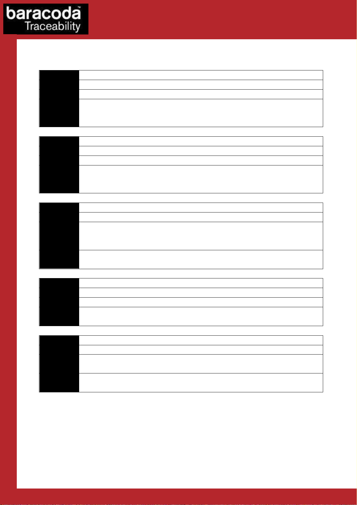
Header: 1 Byte
Length: 2 Bytes (MSB, LSB)
Payload: 0 to 65535 Bytes.
Command
Set Pin Code
Header
0x01 (flash only)
Length
xx xx (new pin size)
Payload
N digits PIN. (Defaut
“0000”)
Response
0x01 00 01 01 if done
Remark
Max Pin length=16
Command
Get Pin Code
Header
0x07
Length
00 00
Payload
N digits PIN. (Défaut “0000”)
Response
0x07 {PinCode size} {Pincode}
Remark
Command
Set Name
Header
0x02
(flash only)
Length
xx xx
Payload
(new name size)
Response
New name 0x02 00 01 01 if done
Remark
(Names up to 248 Bytes)
Command
Get Name
Header
0x08
Length
00 00
Payload
Response
0x08 {name size} {name}
Remark
Name size:
2 Bytes MSB, LSB Names up to 248 Bytes
Command
Set Mode
Header
0x03 (flash only)
Length
00 01
Payload
0x01 if MASTER, 0x00 if SLAVE
Response
0x03 00 01 01 if done
APPENDIX 1
APPENDIX 1:
APPENDIX 1APPENDIX 1
The configuration frames are as follows:
The configuration frames are as follows:
The configuration frames are as follows:The configuration frames are as follows:
Commands
Commands
CommandsCommands
0x01 00 01 00 if not
: Bluetooth Protocol
: :
Bluetooth Protocol
Bluetooth ProtocolBluetooth Protocol
Data Capture
for Workforce
in Motion
0x02 00 01 00 if not
0x03 00 01 00 if not
DualRunners – Communication Protocol v1.3 - 37 -
Page 38

Data Capture
Command
Set Mode
Header
0x03 (flash only)
Length
00 02
Payload
0x01 if MASTER, 0x00 if SLAVE, [Role switch]
Response
0x03 00 01 01 if done
Command
Get Mode
Header
0x04
Length
00 00
Payload
Response
0x04 00 02 {Mode (1byte) | Switch role (1byte)}
Remark
0x01 if MASTER, 0x00 if SLAVE
Command
Set Remote BDA (Used by Master Mode of the SM)
Header
0x05
Length
00 06
Payload
BDA(ex:0x00,0x02,0xC3,0x21, 0xDE,0xFA)
Response
0x05 00 01 01 if done
Remark
If The SM is set to Master
(using Set MODE command), the SM use
Command
Get Remote BDA
Header
0x06
Length
00 00
Payload
Response
0x06 00 06 {6 bytes of BDA}
Remark
for Workforce
0x03 00 01 00 if not
When in Master, the Module connects to the address specified by Set REMOTE BDA or to the last
paired device.
The real MASTER in a Bluetooth piconet is the device which manages the clock used for the
frequency hopping. We used to speak about MASTER too for devices which create the connection
(that's true if you do not switch the clock role)
A device with a slave BT clock role is unable to synchronize more than one master clock. If more than
one SmartModule needs to connect to the same other device (PC, Access Point…) you will need to
switch the clock role to allow the slave to be connected to more than one master. Note that most of
the BT access point already generates the BT clock role switch when a master device creates a
connection.
in Motion
0x01 if want automatic switch role, 0x00 otherwise
0x05 00 01 00 if not
this Address to connect to.
DualRunners – Communication Protocol v1.3 - 38 -
Page 39

Data Capture
Command
Get Bluetooth Version
Header
0x76
Length
00 00
Payload
Response
0x76, x, x, {version string }
Command
Restore Factory Settings
Header
Length
Payload
('R', 's', 't')
Response
Command
Get inquiry scan timeout
Header
0x27
Length
00 00
Payload
Response
0x27 00 04 [Inquiry Interval (MSB) | Inquiry Interval
(LSB) | Inquiry
Remark
Inquiry Interval and Inquiry Window are in number of Bluetooth
Command
Set inquiry scan timeout
Header
0x26
Length
00 04
Payload
Inquiry Interval (MSB) | Inquiry
Interval (LSB) | Inquiry Window
Response
0x26 00 01 01 if done
Remarks
Inquiry Scan TimeOuts are used by the Module to answer to
for Workforce
in Motion
Window (MSB) | Inquiry Window (LSB)]
slots) (1 slot = 0.625 ms)
(MSB) | Inquiry Window (LSB)]
(default 0xC80, 0x18)
0x26 00 01 00 if not
Inquiries. So, if you set both values to 0, the Module will not be
discoverable.
DualRunners – Communication Protocol v1.3 - 39 -
Page 40

Data Capture
Command
Set page scan timeout
Header
0x24
Length
00 04
Payload
[Page Interval (MSB) | Page Interval (LSB) |
Page Window (MSB) |
Response
0x24 00 01 01 if done
Remark
Page Scan TimeOuts are used by the Module to answer to Connect
Command
Get page scan timeout
Header
0x25
Length
00 00
Payload
Response
0x25 00 04 [Page Interval (MSB) | Page Interval (LSB) | Page
Remark
Page Scan Interval and Page Scan Window are in number of
Inquiry Scan
Page Scan
for Workforce
Page Window (LSB)]
(default 0x320, 0xb0)
0x24 00 01 00 if not
Inquiries. So, if you set both values to 0, the Module will not be
Connectable.
in Motion
Window (MSB) | Page Window (LSB)]
Bluetooth slots) (1 slot = 0.625 ms)
Typical values are:
Full power:
Inquiry Interval = 0x400
Inquiry Window = 0x200
Page Scan Interval = 0x400
PageScan Window = 0x200
Low power:
Inquiry Interval = 0x320
Inquiry Window = 0x80
Page Scan Interval = 0x320
PageScan Window = 0x80
Here is how these values change the consumption of the Module:
Window
Window
Page Scan and Inquiry Scan Interval
DualRunners – Communication Protocol v1.3 - 40 -
Page 41

Data Capture
Command
Set sniff
Header
0x09
Length
00 04
Payload
[MSB of
MinSniff interval, LSB of MinSniff interval,
Response
0x09 00 01 01 if done
Remark
Command
Set sniff (advanced)
Header
0x09
Length
00 08
Payload
[MSB of MinSniff interval, LSB
of MinSniff interval,
Response
0x09 00 01 01 if done
Remark
Command
Get Sniff
Header
0x10
Length
00 00
Payload
Response
0x10 00 08 [MSB of MinSniff interval, LSB of MinSniff interval, MSB
Remark
When setting only MinSniff and
MaxSniff values, the default value
for Workforce
MSB of MaxSniff interval, LSB of MaxSnif interval]
0x09 00 01 00 if not
MSB of MaxSniff interval, LSB of MaxSnif interval,
Sniff Attempts MSB, Sniff attempts LSB,
Sniff timeout MSB, Sniff timeout LSB]
in Motion
0x09 00 01 00 if not
of MaxSniff interval, LSB of MaxSnif interval, Sniff Attempts MSB,
Sniff attempts LSB, Sniff timeout MSB, Sniff timeout LSB]
0x08 will be used for Sniff attempts and Sniff timeout.
Typical values are:
Full speed (full power)
MinSniff = 0
MaxSniff = 0
Very Low Power (low speed): (sniff of 500ms Only are accepted. If the remote device does
not support sniffs of 500ms, no sniff will be used)
MinSniff = 0x0320
MaxSniff = 0x0320
Very Low Power (low speed): (sniff between 250ms to 500ms are accepted. No sniff will be
used if the remote device does not support any sniff values in this specified range)
MinSniff = 0x0160
MaxSniff = 0x0320
DualRunners – Communication Protocol v1.3 - 41 -
Page 42

Data Capture
Command
Get link timeout
Header
0x18
Length
00 00
Payload
Response
0x18 00 02 [MSB of link Tmo, LSB of link Tmo]
Remark
Command
Set link timeout
Header
0x19
Length
00 02
Payload
[MSB of link Tmo, LSB of link
Tmo]
Response
0x19 00 01 01 if done
Remark
The link Time Out is a multiple of 625µsec (625µs = 1 Bluetooth
for Workforce
Low Power (medium speed):
MinSniff = 0x0050
MaxSniff = 0x00F0
Attempt = 0x0008
Timeout = 0x0030
MaxSniff and MinSniff are only used for sniff negotiation between the Smart Module and the other
BT device. If both sides allow sniff value MaxSniff, then MaxSniff will be used. If the other side does
not accept Sniff values MinSniff to MaxSniff, no sniff will be used.
Values are in number of Bluetooth slots (1 slot = 625µs)
Set MinSniff and MaxSniff to 0 to disable Sniff.
MinSniff must be inferior to MaxSniff.
Possible values for MinSniff and MaxSniff are 0x12 to 0xFFFF.
Sniff attempts of 0 is not allowed.
Warning: Setting MaxSniff to 0xFF means a sniff period of 40s! You will have very very low data rate.
Note: This setting takes effect immediately.
in Motion
For further details on Sniff values, see the Bluetooth spec 1.1, chapter 10.8.2
slot) (default 0x7D00 (=20s))
This Timeout is use by the Link Manager to monitor the Bluetooth Link. If there is no answer from the
other device after this timeout, the Link Manager assumes that we are disconnected. By default, this
value is set to 20 seconds. You can go down to 1s, but then you can have disconnection even if it’s
only a temporary perturbation.
This value will take effect at the next connection.
DualRunners – Communication Protocol v1.3 - 42 -
Page 43

Data Capture
Command
Get Security Mode
Header
0x20
Length
00 00
Payload
Response
0x20 00 01 01 if secured
Remark
Command
Set Security Mode
Header
0x21
Length
00 {size}
Payload
{00 non secured, 01 secured} {PIN
CODE
Response
0x21 00 01 01 if done,
Remark
Size=PINCODE size + 1
Command
Get Bluetooth class device
Header
0x30
Length
00 00
Payload
Response
0x30 00 04
[Class of device]
Remark
See the Bluetooth specification for more details
Command
Set Bluetooth class device
Header
0x31
Length
00 04
Payload
[Class of Device (4 bytes, MSB
-
>LSB)] (default 0x500)
Response
0x31 00 01 01 if done
for Workforce
0x20 00 01 00 if non secured
(default 01)
in Motion
0x21 00 01 00 if not
For example : 0x21 00 05 00 30 30 30 30 to disable security
0x31 00 01 00 if not
DualRunners – Communication Protocol v1.3 - 43 -
Page 44

Peripheral
0x000500 (default)
Undefined
0x001F00
Phone
0x502204
Computer
0x120104
PDA 0x100114
Access Point
0x120320
Command
Set Remote rfcomm channel
Header
0x36
Length
00 01
Payload
[channel (1byte)]
Response
0x36 00 01 01 if done
Remark
Command
Get Remote rfcomm channel
Header
0x37
Length
00 00
Payload
Response
0x37 00 01 [channel]
Remark
Command
Set Target
Service UUID
Header
0x38
Length
00 02
Payload
[UUID (2 Bytes)]
Response
0x38 00 01 01 if done
Remark
Try to connect to this remote service.
Command
Get Target Service UUID
Header
0x39
Length
00 00
Typical Bluetooth class of device:
Data Capture
for Workforce
in Motion
0x36 00 01 00 if not
If “channel” is not zero, the Module will directly try to connect (if in master mode) to the specified
rfcomm channel.
Setting the channel to zero will force the Module to connect (if in master mode) to the first specified
Remote Service UUID (by default SPP).
The services in the Module are all set to channel 1.
(default 0x1101)
0x38 00 01 00 if not
DualRunners – Communication Protocol v1.3 - 44 -
Page 45

Payload
Response
0x39 00 02 [UUID]
Remark
Try to connect to this remote service.
SPP 0x1101
DUN
0x1103
FAX 0x1102
Command
Get Encryption Mode
Header
0x40
Length
00 00
Payload
Response
0x40 00 01 [encryption]
Remark
Command
Set Encryption Mode
Header
0x41 ( flash only)
Length
00 01
Payload
[Encryption (1 byte)]
Response
0x41 00 01 01 if done
Remark
Argument is: 0x01 to enable encryption,
0x00 to disable.
Command
Get local Bluetooth Address
Header
0x43
Length
00 00
Payload
Response
0x43 00 06 {6 Bytes (BD_address MSB, ..., LSB)}
Remark
Here are some service UUID:
You can get more UUIDs by reading the Bluetooth spec.
Data Capture
for Workforce
in Motion
0x41 00 01 00 if not
DualRunners – Communication Protocol v1.3 - 45 -
Page 46

Data Capture
Code
ID Length
Payload
1 Byte
2 Bytes
N Bytes
Code ID
0x02
Description
Payload
Get : None
Response
Get : 2 bytes:
for Workforce
APPENDIX 2
APPENDIX 2:
APPENDIX 2APPENDIX 2
: RFID communication protocol
: :
RFID communication protocol
RFID communication protocolRFID communication protocol
in Motion
Introduction
Introduction
IntroductionIntroduction
Generalities
Platform2 is supporting a communication interface with an RFID daughter board. Using a UART link,
the communication is possible thanks to a communication protocol described in this document.
Generic packet
All the frames described in this document are formatted as shown:
Commands with codeIDs between 0x00 and 0x7F are configuration commands
Commands with codeIDs between 0x80 and 0xFF are communication commands
Communication protocol
Communication protocol
Communication protocolCommunication protocol
Configuration messages
Get/Set a c ti ve p ro to co ls
Set : 4 bytes (MSB first):
[PROTOCOL_DESELECT_MASK_MSB] [PROTOCOL_DESELECT_MASK_LSB]
[PROTOCOL_MASK_MSB] [PROTOCOL_MASK_LSB]
Cf. below for bits significance
Set : 1 = success
MASK format :
Bit 0 (LSB): ISO/IEC 14443-A (or NXP Mifare)
Bit 1 : ISO/IEC 14443-B
Bit 2 : ISO/IEC 15693 (e.g. TI Tag-it or NXP ICODE-SLI)
Bit 3 : NXP ICODE-1
Bit 4 : Inside Contactless PicoTAG
Bit 5 : S.T. MicroElectronics SR
Bit 6 : ASK CTS256B/CTS512B
Bit 7 : Calypso (Innovatron protocol)
Bit 8 : EPC HF Version 2 (future feature)
Bit 9 : ISO/IEC 15693 in FAST mode
Bit 10 : RFU
DualRunners – Communication Protocol v1.3 - 46 -
Page 47

Data Capture
Code ID
0x03
Description
Payload
Get : None
Response
Get : 1 byte: 1 = enabled, 0 = disabled
ID string
Associated protocol
[A] ISO/IEC 14443
-
A (or NXP Mifare)
[B] ISO/IEC 14443
-B
[C] ISO/IEC
15693 (e.g. TI Tag
-
it or NXP ICODE
-
SLI)
[D] NXP ICODE
-1
[E] Inside Contactless PicoTAG
[F] S.T. MicroElectronics SR
[G] ASK CTS256B/CTS512B
[H] Calypso (Innovatron protocol)
[I] EPC HF Version 2
[Z] unknown
Code ID
0x04
Description
Payload
None
Response
4 bytes:
for Workforce
Bit 11 : RFU
Bit 12 : RFU
Bit 13 : RFU
Bit 14 : RFU
Bit 15 : RFU
Bit 16 : RFU
For the deselect mask, a set bit masks its configuration.
Example :
The current active protocols mask value is 0xFFFF (all protocols enabled, default value)
We want to disable 14443-A and 14443-B, we also want to be sure 15693 is enabled. We want to
keep the other settings as they are and we do not want to have to make a "get" before the "set".
The 4 bytes for the set command should be : 0x00 0xF8 0x00 0x04
The new active protocols mask value is 0xFFF4
in Motion
Get/Set p r ot o co l Id en ti f ier (ID) t r a nsmission
Set : 1 byte: 1 = enable, 0 = disable
Set : 1 = success
If enabled, IDs are transmitted before the tag UID data:
Get Mif a r e k e ys s t atus ( M a s k )
Bits 0-15 : the A keys (bits 0-3 reserved)
Bits 0-15 : the B keys (bits 0-3 reserved)
A set bit means that a key has been loaded at this emplacement.
DualRunners – Communication Protocol v1.3 - 47 -
Page 48

Data Capture
Remarks
For Mifare cards, a 6
-
byte security key is needed to access the data. The scanner is able
Code ID
0x05
Description
Payload
Restore default keys : None (erases all user defined keys)
Response
1 = success
Code ID
0x07
Description
Get/Set
RFID
Protocol P r e fix
/
Suffix
Payload
Byte 1 : Protocol ID (0
– 9) (see below)
Response
Byte 1 : 1 = success, 0 = failed
Remarks
See command 0x83 for more details about the transparent mode
for Workforce
to handle 16 keys for each of the 2 key sets (A and B defined in Mifare spec.) for each
key set, the 4 first keys are reserved for default keys.
Load M i f a r e k ey(s)
Load a key : 8 bytes
1B : {key set : 0 = A key, 1 = B key}
1B : {key number : 4 to 15}
6B : {the 6 bytes of the key}
in Motion
Following bytes :
List of commands and there parameters (see below)
If Get:
Byte 2 : Protocol ID
Following bytes : list of command and there data
Command List:
RFID_CONFIG_TRAME_SET_PREFIX = 0x14
RFID_CONFIG_TRAME_SET_SUFFIX = 0x15
RFID_CONFIG_TRAME_GET_PREFIX = 0x16
RFID_CONFIG_TRAME_GET_SUFFIX = 0x17
Protocol ID:
ID Associated protocol
0 ISO/IEC 14443-A (or NXP Mifare)
1 ISO/IEC 14443-B
2 ISO/IEC 15693 (e.g. TI Tag-it or NXP ICODE-
SLI)
3 NXP ICODE-1
4 Inside Contactless PicoTAG
5 S.T. MicroElectronics SR
6 ASK CTS256B/CTS512B
7 Calypso (Innovatron protocol)
8 EPC HF Version 2
0xFF All Protocol
DualRunners – Communication Protocol v1.3 - 48 -
Page 49

Data Capture
Code ID
0x76
Description
Payload
None
Response
x bytes:
for Workforce
Get ver s i o n
“TagRunners vx.xx”
in Motion
DualRunners – Communication Protocol v1.3 - 49 -
Page 50

Code ID
0x80
Description
Payload
0-
3bytes:
Response
None if no tag detected
Code ID
0x81
Description
Payload
6 bytes:
Response
x bytes:
Communication messages
Find T A G a n d ge t ID
[optional 2 bytes] : {protocol mask}
[optional 1 byte] : {timeout (s)}
Else x bytes:
{Tag ID}
Read dat a fr o m a TAG
2B : { protocol mask
the mask format is the same as the one used in command 0x02.
if 00 00 is given, then the default mask will be used (the one defined with
command 0x02) }
1B : { timeout
Timeout for the response.
if 00 is given, then the default timeout will be used (5s) }
1B : { expected card type
00 : try any supported card
01 : only try to read mifare ultralight cards
02 : only try to read mifare 1K cards
03 : only try to read mifare 4K cards
ETC. the complete list of card types codes is shown below }
2B : { start/stop sectors (pages)
Start sector must be smaller or equal to stop sector number
For all cards (tags), the first sector (or page, or block) is 0.
For the stop sector, if the specified number is greater than the last sector
available on the tag, the reading will occur until the last sector
Examples :
00 00 : read first sector/page
00 FF : read the whole memory }
Data Capture
for Workforce
in Motion
DualRunners – Communication Protocol v1.3 - 50 -
/!\ only the reading status is encapsulated into the data frame (code ID, length,
payload), before receiving this, the response can be sent :
2B : { protocol type
RF protocol used by the read card (see mask format)
Example : 00 01 = mifare tag }
1B : { UID (tag ID) length }
xB : { UID }
1B : {Card type
00 : try any supported card
Page 51

Data Capture
01 : mifare ultralight card
Code ID
0x82
Description
Payload
7+ bytes:
Response
1 byte: { 1 = success }
for Workforce
02 : mifare 1K card
03 : mifare 4K card
ETC. the complete list of card types codes is shown below }
For each read sector/page:
If Mifare Ultralight :
{1B : page number
4B : data}
If Mifare 1K or 4K :
{1B : sector number
1B : block number
16B : data}
If ISO15693 card from NXP or TI :
{1B : block number
4B : data}
If ISO15693 card from STMicroelectronics :
{1B : block number
1B : data}
in Motion
Write d a t a in t o a TAG
2B : { protocol mask
the mask format is the same as the one used in command 0x02.
if 00 00 is given, then the default mask will be used (the one defined with
command 0x02) }
1B : { timeout
Timeout for the response.
if 00 is given, then the default timeout will be used (5s) }
1B : { card type
00 : try any supported card
01 : write in mifare ultralight cards
02 : write in mifare 1K cards
03 : write in mifare 4K cards
ETC. the complete list of card types codes is shown below }
1B : { start sector
Number of first sector/page to start writing at}
2B : { length (MAX = 256)
Number of bytes to write
/!\ whole sectors will be written. If the specified number of bytes does not
complete one sector, the remaining space will be erased. }
xB : { data }
DualRunners – Communication Protocol v1.3 - 51 -
Page 52

Data Capture
Code
Protocol
Manufacturer
Card type
Compatibility
0x01
ISO 14443
-A
NXP Mifare Ultralight
YES
0x02
ISO 14443
-A
NXP Mifare 1K
YES
0x03
ISO 14443
-A
NXP Mifare 4K
YES
0x04
ISO 14443
-A
NXP Desfire
NO
0x05
ISO 14443
-A
Others (e.g.
ASK)
_ NO
0x06
ISO 14443
-B
Any _ NO
0x07
ISO 15693
NXP I-CODE SLI
YES
0x08
ISO 15693
NXP I-CODE SLI
-L
YES
0x09
ISO 15693
NXP I-CODE SLI
-S
YES
0x0a
ISO 15693
NXP Others
NO
0x0b
ISO 15693
Texas Instruments
Tag-it HF
-
I Plus inlay
YES
0x0c
ISO 15693
Texas Instruments
Tag-it HF
-
I Plus chip
YES
0x0d
ISO 15693
Texas Instruments
Tag-it HF
-
I Standard chip/inlay
YES
0x0e
ISO 15693
Texas Instruments
Tag-it HF
-
I Pro chip/inlay
YES
0x0f ISO 15693
Texas Instruments
Others
NO
0x10
ISO 15693
STMicroelectronics
LRI64
YES
0x11
ISO 15693
STMicroelectronics
Others
NO
0x12
ISO 15693
Legic
Any NO
0x13
ISO 15693
Others
_ NO
Card type
Memory constitution
Mifare Ultralight
64 Bytes:
Mifare 1K
768 Bytes:
Mifare 4K
3456 Bytes:
I-CODE SLI
112 Bytes:
I-CODE SLI
-L
32 Bytes:
I-CODE SLI
-S
160 Bytes:
Tag-it HF
-
I Plus inlay
256 Bytes:
Tag-it HF
-
I Plus chip
256 Bytes:
Tag-it HF
-
I Standard chip/inlay
44 Bytes:
for Workforce
For the two above commands, the complete list of card types codes for read/write compatibility:
in Motion
About the known cards memory constitution :
16 4-byte pages
16 48-byte sectors each constituted of 3 16-byte blocks
32 48-byte sectors each constituted of 3 16-byte blocks
8 240-byte sectors each constituted of 15 16-byte blocks
28 4-byte blocks
8 4-byte blocks
40 4-byte blocks
64 4-byte blocks
DualRunners – Communication Protocol v1.3 - 52 -
64 4-byte blocks
11 4-byte blocks
Page 53

(blocks 8
-
9
UID, block 10
AFI)
Tag-it HF
-
I Pro chip/inlay
48 Bytes:
LRI64
14 Bytes:
Data Capture
for Workforce
in Motion
12 4-byte blocks
(blocks 8-9 UID, block 10 AFI, block 11 password)
14 1-byte blocks
(blocks 0-7 UID, block 8 AFI, block 9 DSFID)
DualRunners – Communication Protocol v1.3 - 53 -
Page 54

Data Capture
for Workforce
APPENDIX 3
APPENDIX 3:
APPENDIX 3APPENDIX 3
(for BlackBerry, Symbian & Java platforms)
(for BlackBerry, Symbian & Java platforms)
(for BlackBerry, Symbian & Java platforms)(for BlackBerry, Symbian & Java platforms)
: RFID tag data read/write examples
RFID tag data read/write examples
: :
RFID tag data read/write examples RFID tag data read/write examples
in Motion
1. Introduction
1.1 Generalities
1.1 Generalities
1.1 Generalities1.1 Generalities
This document describes how developers can read and write RFID tag data with the Baracoda TagRunners
(BRRT) and Baracoda DualRunners (BDR) readers. It can be used on the following platforms (SDKs):
- Blackberry
- Java J2ME phones
- Symbian
Please note that the Full SDK for PC and PDA has a set of commands (ReadTagData, WriteTagData) that can be
used directly.
http://www.baracoda.com
DualRunners – Communication Protocol v1.3 - 54 -
Page 55

Data Capture
for Workforce
2.
2.
Mifare Ultralight tags
2.2.
2.1 Tag memory structure
2.1 Tag memory structure
2.1 Tag memory structure2.1 Tag memory structure
Mifare Ultralight tags have 64 bytes of memory divided into 16 (sixteen) 4-bytes long pages.
2.2 Reading tag data
2.2 Reading tag data
2.2 Reading tag data2.2 Reading tag data
a) Communication diagram
The following diagram shows what needs to be done in order to read the contents of a Mifare Ultralight tag:
Terminal
Send read command to
b) Data sent from the terminal to the reader
First of all, the terminal needs to send to the reader a Read data command to the reader. This command is
described in the communication protocol guide of the reader; its code ID is 0x81. In this case, the format of the
command will be as follows (in hexadecimal):
DE 00 07 81 00 00 1E 01 00 FF
where:
- DE: prefix
- 00 07: data length (7 bytes will follow)
- 81: command ID
- 00 00: protocol mask (it’s best to specify 00 00 for Mifare cards)
- 1E: timeout for the response (30s)
- 01: card type (Mifare Ultralight)
- 00 FF: start/stop sectors/pages (00 FF means read the whole memory)
reader
BRRT or BDR Reader
Send tag data that has been
read
Send end of data packet
in Motion
DualRunners – Communication Protocol v1.3 - 55 -
Page 56

Data Capture
for Workforce
c) Reader’s response (successful read)
If the read operation has been successful, the reader will send the tag ID, the tag data and then an end of data
packet with the success byte set to 1 (one). On the other hand, if the operation has failed, the reader may send
the tag ID and an end of data packet with the success byte set to 0 (zero).
The following is an example of the reader’s response:
00 01 07 xx xx xx xx xx xx xx 01 00 aa bb cc dd 01 ee ff gg hh 02 ... 0F ii jj kk ll DE 00 02 81 01,
where
- 00 01: tag protocol (Mifare Ultralight)
- 07: tag ID length (7 bytes)
- xx xx xx xx xx xx xx: tag ID (tag ID is read-only)
- 01: card type (01 means Mifare Ultralight)
- 00: page id (0)
- aa bb cc dd: 4 bytes of page 0
- 01: page id (1)
- ee ff gg hh: 4 bytes of page 1
- etc...
- 0F: page id (15)
- ii jj kk ll: 4 bytes of page 15
- DE 00 02 81 01: end of data, where 00 02 – length, 81 – command ID, 01 – success status (01 means
success)
Please note that the dump does not show all 16 pages of the tag data. They all have an identical structure:
page id followed by 4 (four) bytes of data. The last byte of the end of data packet is equal to 1 (one), which
means that the read operation has been successful.
d) Reader’s response (read failure)
If the reader cannot read the tag data, the reader’s response will be the following:
[xx xx yy zz zz zz zz vv] DE 00 02 81 00,
where:
- the first part of the response is optional and will be sent only if a tag of a different protocol was read
o xx xx: tag protocol
o yy: tag ID length
o zz zz zz zz: tag ID (yy bytes)
o vv: card type
- DE 00 02 81 00: end of data, where 00 02 – length, 81 – command ID, 00 – success status (01 means
failure)
in Motion
DualRunners – Communication Protocol v1.3 - 56 -
Page 57

Data Capture
for Workforce
2.3 Writing tag data
2.3 Writing tag data
2.3 Writing tag data2.3 Writing tag data
a) Communication diagram
The following diagram shows what needs to be done in order to write the contents of a Mifare Ultralight tag:
Terminal
BRRT or BDR Reader
Send write command to
reader
Confirm that data has been
written
b) Data sent from the terminal to the reader
For every page that needs to be modified, the terminal needs to send a write command to the reader. It is
recommended to verify what parts of the tag data have been modified and send only the differing pages.
In order to write a page, the terminal needs to send to the reader a Write data command to the reader. This
command is described in the communication protocol guide of the reader; its code ID is 0x82. In the example
the user intends to modify page 7 (seven), so the format of the command will be as follows (in hexadecimal):
DE 00 0C 82 00 00 00 01 07 00 04 xx xx xx xx
where:
- DE: prefix
- 00 0C: data length (12 bytes will follow)
- 82: command ID (write tag data)
- 00 00: protocol mask (it’s best to specify 00 00 for Mifare cards)
- 00: timeout for the response (0 means use default = 5s)
- 01: card type (Mifare Ultralight)
- 07: start page (7)
- 00 04: data length (4 bytes)
- xx xx xx xx: data to be written in page 7
in Motion
DualRunners – Communication Protocol v1.3 - 57 -
Page 58

Data Capture
for Workforce
c) Reader’s response (successful write)
If the write operation has been successful, the reader will send an end of data packet with the success byte set
to 1 (one). On the other hand, if the operation has failed, the reader may send the tag ID and an end of data
packet with the success byte set to 0 (zero).
The following is an example of the reader’s response:
DE 00 02 81 01,
where
- DE 00 02 81 01: end of data, where 00 02 – length, 81 – command ID, 01 – success status (01 means
success)
d) Reader’s response (write failure)
If the reader cannot write the tag data, the reader’s response will be the following:
DE 00 02 81 00,
where:
- DE 00 02 81 00: end of data, where 00 02 – length, 81 – command ID, 00 – success status (01 means
failure)
Please note that most Mifare Ultralight cards have pages that are read-only. The developer should not try to
modify those fields as the results are unpredictable (e.g. the reader may report a success even though the
write operation failed). Please refer to the used RFID tag manufacturer specification for more details.
in Motion
DualRunners – Communication Protocol v1.3 - 58 -
Page 59

Data Capture
for Workforce
in Motion
3. Mifare 1K tags
3.1 Tag memory structure
3.1 Tag memory structure
3.1 Tag memory structure3.1 Tag memory structure
Mifare 1K tags have 768 bytes of memory divided into 16 (sixteen) 48-bytes long sectors. Every sector is divided
into 3 (three) 16-bytes long blocks
3.2 Reading tag data
3.2 Reading tag data
3.2 Reading tag data3.2 Reading tag data
a) Communication diagram
The following diagram shows what needs to be done in order to read the contents of a Mifare 1K tag:
Terminal
Send read command to
b) Data sent from the terminal to the reader
First of all, the terminal needs to send to the reader a Read data command to the reader. This command is
described in the communication protocol guide of the reader; its code ID is 0x81. In this case, the format of the
command will be as follows (in hexadecimal):
DE 00 07 81 00 00 1E 02 00 FF
where:
- DE: prefix
- 00 07: data length (7 bytes will follow)
- 81: command ID
- 00 00: protocol mask (it’s best to specify 00 00 for Mifare cards)
- 1E: timeout for the response (30s)
- 02: card type (02 means Mifare 1K)
- 00 FF: start/stop sectors/pages (00 FF means read the whole memory)
reader
BRRT or BDR Reader
Send tag data that has been
read
Send end of data packet
DualRunners – Communication Protocol v1.3 - 59 -
Page 60

Data Capture
for Workforce
c) Reader’s response (successful read)
If the read operation has been successful, the reader will send the tag ID, the tag data and then an end of data
packet with the success byte set to 1 (one). On the other hand, if the operation has failed, the reader may send
the tag ID and an end of data packet with the success byte set to 0 (zero).
The following is an example of the reader’s response:
00 01 04 xx xx xx xx 02 00 00 aa aa .. aa 00 01 bb bb .. bb 00 02 cc cc .. cc 01 00 dd .. 0F 02 ee ee .. ee DE 00 02
81 01,
where
- 00 01: tag protocol (Mifare)
- 04: tag ID length (4 bytes)
- xx xx xx xx: tag ID (tag ID is read-only)
- 02: card type (02 means Mifare 1K)
- 00: sector id (0)
- 00: block id (block 0 of sector 0)
- aa aa .. aa: 16 bytes of block 0, sector 0
- 00: sector id (0)
- 01: block id (block 1 of sector 0)
- bb bb .. bb: 16 bytes of block 1, sector 0
- 00: sector id (0)
- 02: block id (block 2 of sector 0)
- cc cc .. cc: 16 bytes of block 2, sector 0
- 01: sector id (1)
- 00: block id (block 0 of sector 1)
- cc cc .. cc: 16 bytes of block 0, sector 1
- etc...
- 0F: sector id (15)
- 02: block id (block 2 of sector 15)
- ee ee .. ee: 16 bytes of block 2, sector 15
- DE 00 02 81 01: end of data, where 00 02 – length, 81 – command ID, 01 – success status (01 means
success)
Please note that the dump does not show all 16 sectors of the tag data. They all have an identical structure:
(sector id, block id followed by 16 (sixteen) bytes of data) x (3) three times per sector. The last byte of the end
of data packet is equal to 1 (one), which means that the read operation has been successful.
d) Reader’s response (read failure)
If the reader cannot read the tag data, the reader’s response will be the following:
[xx xx yy zz zz zz zz vv] DE 00 02 81 00,
where:
- the first part of the response is optional and will be sent only if a tag of a different protocol was read
o xx xx: tag protocol
o yy: tag ID length
o zz zz zz zz: tag ID (yy bytes)
o vv: card type
in Motion
-
DE 00 02 81 00: end of data, where 00 02 – length, 81 – command ID, 00 – success status (01 means
failure)
DualRunners – Communication Protocol v1.3 - 60 -
Page 61

Data Capture
for Workforce
3.3 Writing tag data
3.3 Writing tag data
3.3 Writing tag data3.3 Writing tag data
a) Communication diagram
The following diagram shows what needs to be done in order to write the contents of a Mifare 1K tag:
Terminal
BRRT or BDR Reader
Send write command to
reader
Confirm that data has been
written
b) Data sent from the terminal to the reader
For every sector that needs to be modified, the terminal needs to send a write command to the reader. It is
recommended to verify what parts of the tag data have been modified and send only the differing sectors.
In order to write a sector, the terminal needs to send to the reader a Write data command to the reader. This
command is described in the communication protocol guide of the reader; its code ID is 0x82. In the example
the user intends to modify sector 0 (zero), so the format of the command will be as follows (in hexadecimal):
DE 00 38 82 00 00 00 02 00 00 30 xx .. xx
where:
- DE: prefix
- 00 38: data length (56 bytes will follow)
- 82: command ID (write tag data)
- 00 00: protocol mask (it’s best to specify 00 00 for Mifare cards)
- 00: timeout for the response (0 means use default = 5s)
- 02: card type (Mifare 1K)
- 00: start sector (0)
- 00 30: data length (48 bytes)
- xx .. xx: 48 bytes of data to be written in sector 0
in Motion
DualRunners – Communication Protocol v1.3 - 61 -
Page 62

Data Capture
for Workforce
c) Reader’s response (successful write)
If the write operation has been successful, the reader will send an end of data packet with the success byte set
to 1 (one). On the other hand, if the operation has failed, the reader may send the tag ID and an end of data
packet with the success byte set to 0 (zero).
The following is an example of the reader’s response:
DE 00 02 81 01,
where
- DE 00 02 81 01: end of data, where 00 02 – length, 81 – command ID, 01 – success status (01 means
success)
d) Reader’s response (write failure)
If the reader cannot write the tag data, the reader’s response will be the following:
DE 00 02 81 00,
where:
- DE 00 02 81 00: end of data, where 00 02 – length, 81 – command ID, 00 – success status (01 means
failure)
Please note that most Mifare 1K cards have pages that are read-only. The developer should not try to modify
those fields as the results are unpredictable (e.g. the reader may report a success even though the write
operation failed). Please refer to the used RFID tag manufacturer specification for more details.
in Motion
DualRunners – Communication Protocol v1.3 - 62 -
Page 63

Data Capture
for Workforce
4.
4.
Mifare 4K tags
4.4.
4.1 Tag memory structure
4.1 Tag memory structure
4.1 Tag memory structure4.1 Tag memory structure
Mifare 4K tags have 3456 bytes of memory divided into:
- 32 (thirty-two) 48-bytes long sectors. Every such sector is divided into 3 (three) 16-bytes long blocks
- 8 (eight) 240-bytes long sectors. Every such sector is divided into 15 (fifteen) 16-bytes long blocks.
4.2 Reading tag data
4.2 Reading tag data
4.2 Reading tag data4.2 Reading tag data
a) Communication diagram
The following diagram shows what needs to be done in order to read the contents of a Mifare 4K tag:
Terminal
Send read command to
b) Data sent from the terminal to the reader
First of all, the terminal needs to send to the reader a Read data command to the reader. This command is
described in the communication protocol guide of the reader; its code ID is 0x81. In this case, the format of the
command will be as follows (in hexadecimal):
DE 00 07 81 00 00 1E 03 00 FF
where:
- DE: prefix
- 00 07: data length (7 bytes will follow)
- 81: command ID
- 00 00: protocol mask (it’s best to specify 00 00 for Mifare cards)
- 1E: timeout for the response (30s)
- 03: card type (03 means Mifare 4K)
- 00 FF: start/stop sectors/pages (00 FF means read the whole memory)
c) Reader’s response (successful read)
reader
BRRT or BDR Reader
Send tag data that has been
read
Send end of data packet
in Motion
DualRunners – Communication Protocol v1.3 - 63 -
Page 64

Data Capture
for Workforce
If the read operation has been successful, the reader will send the tag ID, the tag data and then an end of data
packet with the success byte set to 1 (one). On the other hand, if the operation has failed, the reader may send
the tag ID and an end of data packet with the success byte set to 0 (zero).
The following is an example of the reader’s response:
00 01 04 xx xx xx xx 02 00 00 aa aa .. aa 00 01 bb bb .. bb 00 02 cc cc .. cc 01 00 dd .. 27 0E ee ee .. ee DE 00 02
81 01,
where
- 00 01: tag protocol (Mifare)
- 04: tag ID length (4 bytes)
- xx xx xx xx: tag ID (tag ID is read-only)
- 03: card type (03 means Mifare 4K)
- 00: sector id (0)
- 00: block id (block 0 of sector 0)
- aa aa .. aa: 16 bytes of block 0, sector 0
- 00: sector id (0)
- 01: block id (block 1 of sector 0)
- bb bb .. bb: 16 bytes of block 1, sector 0
- 00: sector id (0)
- 02: block id (block 2 of sector 0)
- cc cc .. cc: 16 bytes of block 2, sector 0
- 01: sector id (1)
- 00: block id (block 0 of sector 1)
- cc cc .. cc: 16 bytes of block 0, sector 1
- etc...
- 27: sector id (39)
- 0E: block id (block 14 of sector 39)
- ee ee .. ee: 16 bytes of block 14, sector 39
- DE 00 02 81 01: end of data, where 00 02 – length, 81 – command ID, 01 – success status (01 means
success)
Please note that the dump does not show all 40 sectors of the tag data. The first 32 (thirty-two) sectors all have
an identical structure: (sector id, block id followed by 16 (sixteen) bytes of data) x (3) three times per sector.
The next eight (8) sectors’ structure is: (sector id, block id followed by 16 (sixteen) bytes of data) x (15) fifteen
times per sector. The last byte of the end of data packet is equal to 1 (one), which means that the read
operation has been successful.
in Motion
DualRunners – Communication Protocol v1.3 - 64 -
Page 65

d) Reader’s response (read failure)
If the reader cannot read the tag data, the reader’s response will be the following:
[xx xx yy zz zz zz zz vv] DE 00 02 81 00,
where:
- the first part of the response is optional and will be sent only if a tag of a different protocol was read
o xx xx: tag protocol
o yy: tag ID length
o zz zz zz zz: tag ID (yy bytes)
o vv: card type
-
DE 00 02 81 00: end of data, where 00 02 – length, 81 – command ID, 00 – success status (01 means
failure)
Data Capture
for Workforce
in Motion
DualRunners – Communication Protocol v1.3 - 65 -
Page 66

Data Capture
for Workforce
4.3 Writing tag data
4.3 Writing tag data
4.3 Writing tag data4.3 Writing tag data
a) Communication diagram
The following diagram shows what needs to be done in order to write the contents of a Mifare 4K tag:
Terminal
BRRT or BDR Reader
Send write command to
reader
Confirm that data has been
written
b) Data sent from the terminal to the reader
For every sector that needs to be modified, the terminal needs to send a write command to the reader. It is
recommended to verify what parts of the tag data have been modified and send only the differing sectors.
In order to write a sector, the terminal needs to send to the reader a Write data command to the reader. This
command is described in the communication protocol guide of the reader; its code ID is 0x82. In the example
the user intends to modify sector 0 (zero) and then 39 (thirty-nine), so the format of the command will be as
follows (in hexadecimal):
DE 00 38 82 00 00 00 03 00 00 30 xx .. xx
where:
- DE: prefix
- 00 38: data length (56 bytes will follow)
- 82: command ID (write tag data)
- 00 00: protocol mask (it’s best to specify 00 00 for Mifare cards)
- 00: timeout for the response (0 means use default = 5s)
- 03: card type (Mifare 4K)
- 00: start sector (0)
- 00 30: data length (48 bytes)
- xx .. xx: 48 bytes of data to be written in sector 0
As soon as the reader has confirmed that the data has been written (please check the next section), the
developer can proceed to writing sector 39 (next page):
in Motion
DualRunners – Communication Protocol v1.3 - 66 -
Page 67

Data Capture
for Workforce
DE 00 F8 82 00 00 00 03 27 00 F0 yy .. yy
where:
- DE: prefix
- 00 F8: data length (248 bytes will follow)
- 82: command ID (write tag data)
- 00 00: protocol mask (it’s best to specify 00 00 for Mifare cards)
- 00: timeout for the response (0 means use default = 5s)
- 03: card type (Mifare 4K)
- 27: start sector (39)
- 00 F0: data length (240 bytes)
- yy .. yy: 240 bytes of data to be written in sector 39
To sum up, the developer should remember that the first 32 (thirty-two sectors) are 48-bytes long and the last
8 (eight) have a length of 240 (two hundred and forty) bytes.
c) Reader’s response (successful write)
If the write operation has been successful, the reader will send an end of data packet with the success byte set
to 1 (one). On the other hand, if the operation has failed, the reader may send the tag ID and an end of data
packet with the success byte set to 0 (zero).
The following is an example of the reader’s response:
DE 00 02 81 01,
where
- DE 00 02 81 01: end of data, where 00 02 – length, 81 – command ID, 01 – success status (01 means
success)
d) Reader’s response (write failure)
If the reader cannot write the tag data, the reader’s response will be the following:
DE 00 02 81 00,
where:
- DE 00 02 81 00: end of data, where 00 02 – length, 81 – command ID, 00 – success status (01 means
failure)
Please note that most Mifare 4K cards have pages that are read-only. The developer should not try to modify
those fields as the results are unpredictable (e.g. the reader may report a success even though the write
operation failed). Please refer to the used RFID tag manufacturer specification for more details.
in Motion
DualRunners – Communication Protocol v1.3 - 67 -
Page 68

Data Capture
for Workforce
5.
5.
Tag-it HF-I Plus inlay tags
5.5.
5.1 Tag memory structure
5.1 Tag memory structure
5.1 Tag memory structure5.1 Tag memory structure
Tag-it HF-I Plus inlay tags have 256 bytes of memory divided into 64 (sixty-four) 4-bytes long blocks.
5.2 Reading tag data
5.2 Reading tag data
5.2 Reading tag data5.2 Reading tag data
a) Communication diagram
The following diagram shows what needs to be done in order to read the contents of a Tag-it HF-I Plus inlay
tag:
Terminal
Send read command to
b) Data sent from the terminal to the reader
First of all, the terminal needs to send to the reader a Read data command to the reader. This command is
described in the communication protocol guide of the reader; its code ID is 0x81. In this case, the format of the
command will be as follows (in hexadecimal):
DE 00 07 81 00 04 1E 0B 00 FF
where:
- DE: prefix
- 00 07: data length (7 bytes will follow)
- 81: command ID
- 00 04: protocol mask (ISO 15693 for Tag-it HF-I Plus inlay)
- 1E: timeout for the response (30s)
- 0B: card type (Tag-it HF-I Plus inlay)
- 00 FF: start/stop sectors/pages (00 FF means read the whole memory)
reader
BRRT or BDR Reader
Send tag data that has been
read
Send end of data packet
in Motion
DualRunners – Communication Protocol v1.3 - 68 -
Page 69

Data Capture
for Workforce
c) Reader’s response (successful read)
If the read operation has been successful, the reader will send the tag ID, the tag data and then an end of data
packet with the success byte set to 1 (one). On the other hand, if the operation has failed, the reader may send
the tag ID and an end of data packet with the success byte set to 0 (zero).
The following is an example of the reader’s response:
00 04 08 xx xx xx xx xx xx xx xx 0B 00 aa bb cc dd 01 ee ff gg hh 02 ... 3F ii jj kk ll DE 00 02 81 01,
where
- 00 04: tag protocol (ISO 15693 for Tag-it HF-I Plus inlay)
- 08: tag ID length (8 bytes)
- xx xx xx xx xx xx xx xx: tag ID (tag ID is read-only)
- 0B: card type (0B means Tag-it HF-I Plus inlay)
- 00: block id (0)
- aa bb cc dd: 4 bytes of block 0
- 01: block id (1)
- ee ff gg hh: 4 bytes of block 1
- etc...
- 3F: block id (63)
- ii jj kk ll: 4 bytes of block 63
- DE 00 02 81 01: end of data, where 00 02 – length, 81 – command ID, 01 – success status (01 means
success)
Please note that the dump does not show all 64 blocks of the tag data. They all have an identical structure:
block id followed by 4 (four) bytes of data. The last byte of the end of data packet is equal to 1 (one), which
means that the read operation has been successful.
d) Reader’s response (read failure)
If the reader cannot read the tag data, the reader’s response will be the following:
[xx xx yy zz zz zz zz vv] DE 00 02 81 00,
where:
- the first part of the response is optional and will be sent only if a tag of a different protocol was read
o xx xx: tag protocol
o yy: tag ID length
o zz zz zz zz: tag ID (yy bytes)
o vv: card type
- DE 00 02 81 00: end of data, where 00 02 – length, 81 – command ID, 00 – success status (01 means
failure)
in Motion
DualRunners – Communication Protocol v1.3 - 69 -
Page 70

Data Capture
for Workforce
5.3
5.3 Writing tag data
5.35.3
Writing tag data
Writing tag dataWriting tag data
a) Communication diagram
The following diagram shows what needs to be done in order to write the contents of a Tag-it HF-I Plus inlay
tag:
Terminal
BRRT or BDR Reader
Send write command to
reader
Confirm that data has been
written
b) Data sent from the terminal to the reader
For every block that needs to be modified, the terminal needs to send a write command to the reader. It is
recommended to verify what parts of the tag data have been modified and send only the differing blocks.
In order to write a page, the terminal needs to send to the reader a Write data command to the reader. This
command is described in the communication protocol guide of the reader; its code ID is 0x82. In the example
the user intends to modify block 3 (three), so the format of the command will be as follows (in hexadecimal):
DE 00 0C 82 00 04 00 0B 03 00 04 xx xx xx xx
where:
- DE: prefix
- 00 0C: data length (12 bytes will follow)
- 82: command ID (write tag data)
- 00 04: protocol mask (ISO 15693 for Tag-it HF-I Plus inlay)
- 00: timeout for the response (0 means use default = 5s)
- 0B: card type (Tag-it HF-I Plus inlay)
- 03: start block (3)
- 00 04: data length (4 bytes)
- xx xx xx xx: data to be written in block 3
in Motion
DualRunners – Communication Protocol v1.3 - 70 -
Page 71

Data Capture
for Workforce
c) Reader’s response (successful write)
If the write operation has been successful, the reader will send an end of data packet with the success byte set
to 1 (one). On the other hand, if the operation has failed, the reader may send the tag ID and an end of data
packet with the success byte set to 0 (zero).
The following is an example of the reader’s response:
DE 00 02 81 01,
where
- DE 00 02 81 01: end of data, where 00 02 – length, 81 – command ID, 01 – success status (01 means
success)
d) Reader’s response (write failure)
If the reader cannot write the tag data, the reader’s response will be the following:
DE 00 02 81 00,
where:
- DE 00 02 81 00: end of data, where 00 02 – length, 81 – command ID, 00 – success status (01 means
failure)
in Motion
DualRunners – Communication Protocol v1.3 - 71 -
Page 72

Data Capture
for Workforce
6.
6.
Tag-it HF-I Plus chip tags
6.6.
6.1 Tag memory structure
6.1 Tag memory structure
6.1 Tag memory structure6.1 Tag memory structure
Tag-it HF-I Plus chip tags have 256 bytes of memory divided into 64 (sixty-four) 4-bytes long blocks.
6.2 Reading tag data
6.2 Reading tag data
6.2 Reading tag data6.2 Reading tag data
a) Communication diagram
The following diagram shows what needs to be done in order to read the contents of a Tag-it HF-I Plus chip tag:
Terminal
Send read command to
b) Data sent from the terminal to the reader
First of all, the terminal needs to send to the reader a Read data command to the reader. This command is
described in the communication protocol guide of the reader; its code ID is 0x81. In this case, the format of the
command will be as follows (in hexadecimal):
DE 00 07 81 00 04 1E 0C 00 FF
where:
- DE: prefix
- 00 07: data length (7 bytes will follow)
- 81: command ID
- 00 04: protocol mask (ISO 15693 for Tag-it HF-I Plus chip)
- 1E: timeout for the response (30s)
- 0C: card type (Tag-it HF-I Plus chip)
- 00 FF: start/stop sectors/pages (00 FF means read the whole memory)
reader
BRRT or BDR Reader
Send tag data that has been
read
Send end of data packet
in Motion
DualRunners – Communication Protocol v1.3 - 72 -
Page 73

Data Capture
for Workforce
c) Reader’s response (successful read)
If the read operation has been successful, the reader will send the tag ID, the tag data and then an end of data
packet with the success byte set to 1 (one). On the other hand, if the operation has failed, the reader may send
the tag ID and an end of data packet with the success byte set to 0 (zero).
The following is an example of the reader’s response:
00 04 08 xx xx xx xx xx xx xx xx 0C 00 aa bb cc dd 01 ee ff gg hh 02 ... 3F ii jj kk ll DE 00 02 81 01,
where
- 00 04: tag protocol (ISO 15693 for Tag-it HF-I Plus chip)
- 08: tag ID length (8 bytes)
- xx xx xx xx xx xx xx xx: tag ID (tag ID is read-only)
- 0C: card type (0C means Tag-it HF-I Plus chip)
- 00: block id (0)
- aa bb cc dd: 4 bytes of block 0
- 01: block id (1)
- ee ff gg hh: 4 bytes of block 1
- etc...
- 3F: block id (63)
- ii jj kk ll: 4 bytes of block 63
- DE 00 02 81 01: end of data, where 00 02 – length, 81 – command ID, 01 – success status (01 means
success)
Please note that the dump does not show all 64 blocks of the tag data. They all have an identical structure:
block id followed by 4 (four) bytes of data. The last byte of the end of data packet is equal to 1 (one), which
means that the read operation has been successful.
d) Reader’s response (read failure)
If the reader cannot read the tag data, the reader’s response will be the following:
[xx xx yy zz zz zz zz vv] DE 00 02 81 00,
where:
- the first part of the response is optional and will be sent only if a tag of a different protocol was read
o xx xx: tag protocol
o yy: tag ID length
o zz zz zz zz: tag ID (yy bytes)
o vv: card type
- DE 00 02 81 00: end of data, where 00 02 – length, 81 – command ID, 00 – success status (01 means
failure)
in Motion
DualRunners – Communication Protocol v1.3 - 73 -
Page 74

Data Capture
for Workforce
6.3 Writing tag data
6.3 Writing tag data
6.3 Writing tag data6.3 Writing tag data
a) Communication diagram
The following diagram shows what needs to be done in order to write the contents of a Tag-it HF-I Plus chip
tag:
Terminal
BRRT or BDR Reader
Send write command to
reader
Confirm that data has been
written
b) Data sent from the terminal to the reader
For every block that needs to be modified, the terminal needs to send a write command to the reader. It is
recommended to verify what parts of the tag data have been modified and send only the differing blocks.
In order to write a page, the terminal needs to send to the reader a Write data command to the reader. This
command is described in the communication protocol guide of the reader; its code ID is 0x82. In the example
the user intends to modify block 3 (three), so the format of the command will be as follows (in hexadecimal):
DE 00 0C 82 00 04 00 0C 03 00 04 xx xx xx xx
where:
- DE: prefix
- 00 0C: data length (12 bytes will follow)
- 82: command ID (write tag data)
- 00 04: protocol mask (ISO 15693 for Tag-it HF-I Plus chip)
- 00: timeout for the response (0 means use default = 5s)
- 0C: card type (Tag-it HF-I Plus chip)
- 03: start block (3)
- 00 04: data length (4 bytes)
- xx xx xx xx: data to be written in block 3
in Motion
DualRunners – Communication Protocol v1.3 - 74 -
Page 75

Data Capture
for Workforce
c) Reader’s response (successful write)
If the write operation has been successful, the reader will send an end of data packet with the success byte set
to 1 (one). On the other hand, if the operation has failed, the reader may send the tag ID and an end of data
packet with the success byte set to 0 (zero).
The following is an example of the reader’s response:
DE 00 02 81 01,
where
- DE 00 02 81 01: end of data, where 00 02 – length, 81 – command ID, 01 – success status (01 means
success)
d) Reader’s response (write failure)
If the reader cannot write the tag data, the reader’s response will be the following:
DE 00 02 81 00,
where:
- DE 00 02 81 00: end of data, where 00 02 – length, 81 – command ID, 00 – success status (01 means
failure)
in Motion
DualRunners – Communication Protocol v1.3 - 75 -
Page 76

Data Capture
for Workforce
7.
7.
I-CODE SLI tags
7.7.
7.1 Tag memory structure
7.1 Tag memory structure
7.1 Tag memory structure7.1 Tag memory structure
I-CODE SLI tags have 112 bytes of memory divided into 28 (twenty-eight) 4-bytes long blocks.
7.2 Reading tag data
7.2 Reading tag data
7.2 Reading tag data7.2 Reading tag data
a) Communication diagram
The following diagram shows what needs to be done in order to read the contents of an I-CODE SLI tag:
Terminal
Send read command to
b) Data sent from the terminal to the reader
First of all, the terminal needs to send to the reader a Read data command to the reader. This command is
described in the communication protocol guide of the reader; its code ID is 0x81. In this case, the format of the
command will be as follows (in hexadecimal):
DE 00 07 81 00 04 1E 07 00 FF
where:
- DE: prefix
- 00 07: data length (7 bytes will follow)
- 81: command ID
- 00 04: protocol mask (ISO 15693 for I-CODE SLI)
- 1E: timeout for the response (30s)
- 07: card type (I-CODE SLI)
- 00 FF: start/stop sectors/pages (00 FF means read the whole memory)
reader
BRRT or BDR Reader
Send tag data that has been
read
Send end of data packet
in Motion
DualRunners – Communication Protocol v1.3 - 76 -
Page 77

Data Capture
for Workforce
c) Reader’s response (successful read)
If the read operation has been successful, the reader will send the tag ID, the tag data and then an end of data
packet with the success byte set to 1 (one). On the other hand, if the operation has failed, the reader may send
the tag ID and an end of data packet with the success byte set to 0 (zero).
The following is an example of the reader’s response:
00 04 08 xx xx xx xx xx xx xx xx 07 00 aa bb cc dd 01 ee ff gg hh 02 ... 1B ii jj kk ll DE 00 02 81 01,
where
- 00 04: tag protocol (ISO 15693 for I-CODE SLI)
- 08: tag ID length (8 bytes)
- xx xx xx xx xx xx xx xx: tag ID (tag ID is read-only)
- 07: card type (07 means I-CODE SLI)
- 00: block id (0)
- aa bb cc dd: 4 bytes of block 0
- 01: block id (1)
- ee ff gg hh: 4 bytes of block 1
- etc...
- 1B: block id (27)
- ii jj kk ll: 4 bytes of block 27
- DE 00 02 81 01: end of data, where 00 02 – length, 81 – command ID, 01 – success status (01 means
success)
Please note that the dump does not show all 28 blocks of the tag data. They all have an identical structure:
block id followed by 4 (four) bytes of data. The last byte of the end of data packet is equal to 1 (one), which
means that the read operation has been successful.
d) Reader’s response (read failure)
If the reader cannot read the tag data, the reader’s response will be the following:
[xx xx yy zz zz zz zz vv] DE 00 02 81 00,
where:
- the first part of the response is optional and will be sent only if a tag of a different protocol was read
o xx xx: tag protocol
o yy: tag ID length
o zz zz zz zz: tag ID (yy bytes)
o vv: card type
- DE 00 02 81 00: end of data, where 00 02 – length, 81 – command ID, 00 – success status (01 means
failure)
in Motion
DualRunners – Communication Protocol v1.3 - 77 -
Page 78

Data Capture
for Workforce
7.3 Writing tag data
7.3 Writing tag data
7.3 Writing tag data7.3 Writing tag data
a) Communication diagram
The following diagram shows what needs to be done in order to write the contents of an I-CODE SLI tag:
Terminal
BRRT or BDR Reader
Send write command to
reader
Confirm that data has been
written
b) Data sent from the terminal to the reader
For every block that needs to be modified, the terminal needs to send a write command to the reader. It is
recommended to verify what parts of the tag data have been modified and send only the differing blocks.
In order to write a page, the terminal needs to send to the reader a Write data command to the reader. This
command is described in the communication protocol guide of the reader; its code ID is 0x82. In the example
the user intends to modify block 3 (three), so the format of the command will be as follows (in hexadecimal):
DE 00 0C 82 00 04 00 07 03 00 04 xx xx xx xx
where:
- DE: prefix
- 00 0C: data length (12 bytes will follow)
- 82: command ID (write tag data)
- 00 04: protocol mask (ISO 15693 for I-CODE SLI)
- 00: timeout for the response (0 means use default = 5s)
- 07: card type (I-CODE SLI)
- 03: start block (3)
- 00 04: data length (4 bytes)
- xx xx xx xx: data to be written in block 3
in Motion
DualRunners – Communication Protocol v1.3 - 78 -
Page 79

Data Capture
for Workforce
c) Reader’s response (successful write)
If the write operation has been successful, the reader will send an end of data packet with the success byte set
to 1 (one). On the other hand, if the operation has failed, the reader may send the tag ID and an end of data
packet with the success byte set to 0 (zero).
The following is an example of the reader’s response:
DE 00 02 81 01,
where
- DE 00 02 81 01: end of data, where 00 02 – length, 81 – command ID, 01 – success status (01 means
success)
d) Reader’s response (write failure)
If the reader cannot write the tag data, the reader’s response will be the following:
DE 00 02 81 00,
where:
- DE 00 02 81 00: end of data, where 00 02 – length, 81 – command ID, 00 – success status (01 means
failure)
in Motion
DualRunners – Communication Protocol v1.3 - 79 -
Page 80

Data Capture
for Workforce
8.
8.
I-CODE SLI-S tags
8.8.
8.1 Tag memory structure
8.1 Tag memory structure
8.1 Tag memory structure8.1 Tag memory structure
I-CODE SLI-S tags have 160 bytes of memory divided into 40 (forty) 4-bytes long blocks.
8.2 Reading tag data
8.2 Reading tag data
8.2 Reading tag data8.2 Reading tag data
a) Communication diagram
The following diagram shows what needs to be done in order to read the contents of an I-CODE SLI-S tag:
Terminal
Send read command to
b) Data sent from the terminal to the reader
First of all, the terminal needs to send to the reader a Read data command to the reader. This command is
described in the communication protocol guide of the reader; its code ID is 0x81. In this case, the format of the
command will be as follows (in hexadecimal):
DE 00 07 81 00 04 1E 09 00 FF
where:
- DE: prefix
- 00 07: data length (7 bytes will follow)
- 81: command ID
- 00 04: protocol mask (ISO 15693 for I-CODE SLI-S)
- 1E: timeout for the response (30s)
- 09: card type (I-CODE SLI-S)
- 00 FF: start/stop sectors/pages (00 FF means read the whole memory)
reader
BRRT or BDR Reader
Send tag data that has been
read
Send end of data packet
in Motion
DualRunners – Communication Protocol v1.3 - 80 -
Page 81

Data Capture
for Workforce
c) Reader’s response (successful read)
If the read operation has been successful, the reader will send the tag ID, the tag data and then an end of data
packet with the success byte set to 1 (one). On the other hand, if the operation has failed, the reader may send
the tag ID and an end of data packet with the success byte set to 0 (zero).
The following is an example of the reader’s response:
00 04 08 xx xx xx xx xx xx xx xx 09 00 aa bb cc dd 01 ee ff gg hh 02 ... 27 ii jj kk ll DE 00 02 81 01,
where
- 00 04: tag protocol (ISO 15693 for I-CODE SLI-S)
- 08: tag ID length (8 bytes)
- xx xx xx xx xx xx xx xx: tag ID (tag ID is read-only)
- 09: card type (09 means I-CODE SLI-S)
- 00: block id (0)
- aa bb cc dd: 4 bytes of block 0
- 01: block id (1)
- ee ff gg hh: 4 bytes of block 1
- etc...
- 27: block id (39)
- ii jj kk ll: 4 bytes of block 39
- DE 00 02 81 01: end of data, where 00 02 – length, 81 – command ID, 01 – success status (01 means
success)
Please note that the dump does not show all 40 blocks of the tag data. They all have an identical structure:
block id followed by 4 (four) bytes of data. The last byte of the end of data packet is equal to 1 (one), which
means that the read operation has been successful.
d) Reader’s response (read failure)
If the reader cannot read the tag data, the reader’s response will be the following:
[xx xx yy zz zz zz zz vv] DE 00 02 81 00,
where:
- the first part of the response is optional and will be sent only if a tag of a different protocol was read
o xx xx: tag protocol
o yy: tag ID length
o zz zz zz zz: tag ID (yy bytes)
o vv: card type
- DE 00 02 81 00: end of data, where 00 02 – length, 81 – command ID, 00 – success status (01 means
failure)
in Motion
DualRunners – Communication Protocol v1.3 - 81 -
Page 82

Data Capture
for Workforce
8.3 Writing tag data
8.3 Writing tag data
8.3 Writing tag data8.3 Writing tag data
a) Communication diagram
The following diagram shows what needs to be done in order to write the contents of an I-CODE SLI-S tag:
Terminal
BRRT or BDR Reader
Send write command to
reader
Confirm that data has been
written
b) Data sent from the terminal to the reader
For every block that needs to be modified, the terminal needs to send a write command to the reader. It is
recommended to verify what parts of the tag data have been modified and send only the differing blocks.
In order to write a page, the terminal needs to send to the reader a Write data command to the reader. This
command is described in the communication protocol guide of the reader; its code ID is 0x82. In the example
the user intends to modify block 3 (three), so the format of the command will be as follows (in hexadecimal):
DE 00 0C 82 00 04 00 09 03 00 04 xx xx xx xx
where:
- DE: prefix
- 00 0C: data length (12 bytes will follow)
- 82: command ID (write tag data)
- 00 04: protocol mask (ISO 15693 for I-CODE SLI-S)
- 00: timeout for the response (0 means use default = 5s)
- 09: card type (I-CODE SLI-S)
- 03: start block (3)
- 00 04: data length (4 bytes)
- xx xx xx xx: data to be written in block 3
in Motion
DualRunners – Communication Protocol v1.3 - 82 -
Page 83

Data Capture
for Workforce
c) Reader’s response (successful write)
If the write operation has been successful, the reader will send an end of data packet with the success byte set
to 1 (one). On the other hand, if the operation has failed, the reader may send the tag ID and an end of data
packet with the success byte set to 0 (zero).
The following is an example of the reader’s response:
DE 00 02 81 01,
where
- DE 00 02 81 01: end of data, where 00 02 – length, 81 – command ID, 01 – success status (01 means
success)
d) Reader’s response (write failure)
If the reader cannot write the tag data, the reader’s response will be the following:
DE 00 02 81 00,
where:
- DE 00 02 81 00: end of data, where 00 02 – length, 81 – command ID, 00 – success status (01 means
failure)
in Motion
DualRunners – Communication Protocol v1.3 - 83 -
 Loading...