


BJ-218

• Please do not put vehicle transceiver under the sun overtime, and do
not put in beside the heating equipment.
• Please do not put the vehicle transceiver in the place where is dusty
and moist, and do not put in one the uneven flat.
• If there is smell or smog from vehicle transceivers, please turn off
the power and contact the dealer.
• Using vehicle transceiver when driving may violate traffic rules, please
obey local traffic rules.
Unpacking and Inspection:
Welcome to use radio. Beforeusing,
we suggest you:
• Please check the packaging
of this product if there is damage.
• Please carefully open the
box checking whether the
products are as following
listed table.
• If there is any damzage
or lost of product and its
accessories during
tran sportation, please
contact deale immediately.
Standad Configuration
ITEMS
Machine body
Hnd microphone
Assembly
supporting rack
Power line
j Screws
Instructions
1
QTY
1
1
1
1
1
1
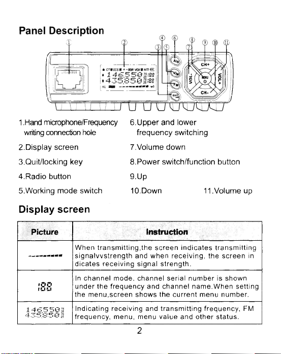
1 .Hand microphone/Frequency
writing connection hole
2.Display screen
3.Quit/locking key
4.Radio button
5.Working mode switch
Display screen
6.Upper and lower
frequency switching
7.Volume down
8.Power switch/function button
9.Up
10.Down 11.Volume up
Picture
;3 8
1 4 6 5 5 0 3
43 5 .8 502 5
Instruction
When tra nsm ittin g,the s c ree n indicates tra ns mitting
sig na lvvs tren gth and when rece iving, the screen in
dica tes receiving sig nal stre n gth.
In ch a n nel mode, channe l serial num b e r is shown
under th e freq ue n cy and channel nam e .Wh e n se tting
the m e nu,scre en show s the curre nt menu number.
Ind icating receivin g and tra ns mittin g freque n cy, FM
frequ e n cy, menu, menu va lue and other statu s.
2
Picture
h
CT
a
DCS
IS
+
-
BDR
VOX
©
N
И
e
Instruction
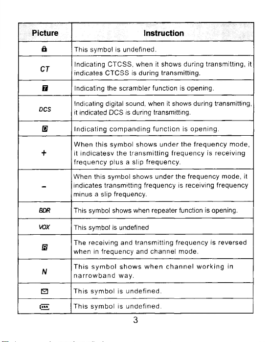
This symbol is undefined.
Indicating CTC S S, when it show s during transm itting, it
indicates CTCSS is during tra n sm itting.
Indicating the scra m ble r function is open ing.
Indicating digital sound, when it shows during transmitting,
it indicated DCS is during transmitting.
Ind icatin g com panding func tion is opening.
When th is sym bol sh o w s und e r the freq ue nc y m o de,
it in d icatesv the tran sm itting frequ e nc y is receivin g
freq ue ncy plu s a slip fre que n cy.
When this symbol shows under the fre q u e n cy mode, it
indicates tra n sm itting fre q uency is receiving fre quency
minus a slip frequency.
This symbol shows when repeater function is opening.
This symbol is undefined
The receiving and transm itting frequenc y is re versed
when in frequ e ncy and channel mode.
Th is sym bol s ho ws w he n ch a nn e l w ork in g in
na rro w b a nd way.
This sym bo l is u n de fin ed .
This sym b ol is u n de fin ed .
3
Picture
ттгО
H
L
4
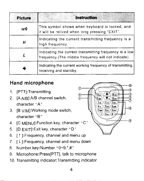
This sym bol show s w hen keyb o ard is loc k ed , and
it w ill be reliv ed when long p re s sing “E XIT ”.
In dic atin g th e c urren t tra ns m ittin g freq ue n cy is a
high fre q uen cy .
In dicatin g the current tran sm ittin g fre q uenc y is a low
freq ue nc y .(T he midd le freq u en cy will not ind icate)
Indicating the current working frequency of transm itting,
receiving and standby.
Instruction
Hand microphone
1. [PTT]:Transmitting
2. [A A/B ]:A /B channel switch,
character “ A ”
3. [B v/M]:Working mode switch,
character “ В ”
4. [С MENU]:Function key, character “C”
5. [D EXIT]:Exit key, character “ D”
6. [ t ]:Frequency, channel and menu up
7. [ I ]:Frequency, channel and menu down
8. Number key:Number “ 0-9,*,#"
9. Microphone:Press[PTT], talk to microphone
10. Transmitting indicator:Transmitting indicator
4
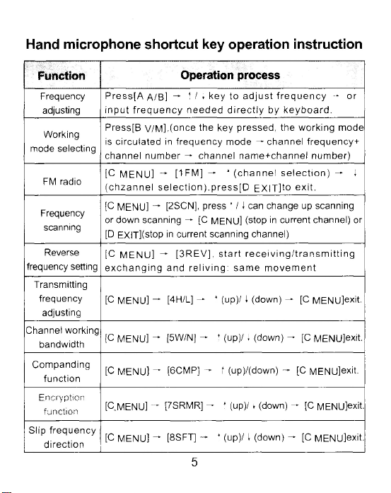
Hand microphone shortcut key operation instruction
Function
Frequency
adjusting
Working
mode selecting
FM radio
Frequency
scanning
Reverse
frequency setting
Transmitting
frequency
adjusting
Channel working
bandwidth
Companding
functio n
Encryption
function
Slip fre q uen c y
direction
Operation process
Pres s[A д/В ] f / i ke y to a dju st fre que nc y -* or
in pu t freq uen cy need e d dire ctly by k ey b oa rd .
Press[B v/M ],(once the key pressed, the working mode
is circula ted in frequ e n cy mode — channel frequency+
cha nnel nu m ber — channel nam e+channel num b e r)
[C M EN U] [1 FM ] — t (c ha nn el selec tio n) — 1
(c hzan n el sele ctio n ),p re ss [D E XITjto ex it.
[C MENU] [2SCN], press t / 1 can change up scanning
or down scanning — [C MENU] (stop in current channel) or
[D EXIT](stop in current scanning channel)
[C ME NU ] [3R EV ], s tart re ce iv ing /tra nsm ittin g
exc ha nging and re living : sa m e m ovem en t
[C MENU] ^ [4H/L] - t (up)/ 1 (down) - [C MENU]exit.
[C MENU] ^ [5W/N] - f (u p)/, (down) - [C MENU]exit.
[C MENU] - [6CMP] - t (up)/(down) - [C MENU]exit.
[C MENU] [7SRMR] - t (up )/1 (down) - [C MENU]exit.
[C MENU] - [8SFT] - t (up)/ 1 (dow n) - [C MENU]exit.
5
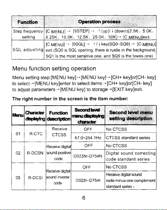
Function
Step frequency
setting
SQL a dju stin g
[C MEN U] - [9STEP] -* + (up)/ i (down)(2 .5K , 5.OK.
6.25 K , 10.OK, 12.5 K , 25.ОК. 5 0K ) - [C MENU]exit.
[C MENU] — [OSQL] — t / i key(SQ0~SQ9) - [C MENU]
exit.(SQ0 is SQL opening, there is rustle in the background,
SQ1 is the most sensitive one, and SQ9 is the lowes one)
Operation process
Menu function setting operation
Menu setting step:[MENU key]-*[MENU key]-^[CH+ key]or[CH- key]
to select^ [MENU key]enter to select items^[CH+ key]or[CH- key]
to adjust parameters-^[MENU key] to storage-^[EXIT keyjexit.
The right number in the screen is the item number:
M en u
01
02
03
Ch a r ac t e r
R-CTC
R-DCSN
R-DCSI
Fun ctio n
desc riptio n
Receive
CTCSS
Receive digital
sound positive
code
Receive digital
sound inverse
code
Se co n d le v el
menu displaying
ch ar ac te r
OFF No CTCSS
67.0 -254 .1 Hz CTCSS standard series
OFF
D023N-D754N
OFF
D023I-D 754I
Second level menu
setting description
No CTCSS
Digital s o und co rrec ting
code stan d ard se ries
No C TCSS
Receive digital sound
radix-minus-one complement
standard series •
6
 Loading...