

Page 1
VTB Pick-to-Light Optical Touch Button
0 067570 5
Ergonomic optical touch button for pick-to-light applications
• Microcontroller-based photoelectric touch buttons
• A cost-effective and easy-to-install alternative to capacitive touch switches and mechanical
push buttons for errorproofing and parts-verification applications
• Ergonomically designed to eliminate hand, wrist, and arm stresses associated with repeated switch operation; requires no physical pressure to operate
• Illuminated base provides a bright, easy-to-see job light in one or two colors, depending on
model
• LED power and output indicators
• NPN or PNP output, depending on model
• Immune to ambient light, EMI and RFI interference
• High excess gain cuts through heavy airborne contamination to function in almost any environment; optional protective field cover available
• 12 to 30V dc operation
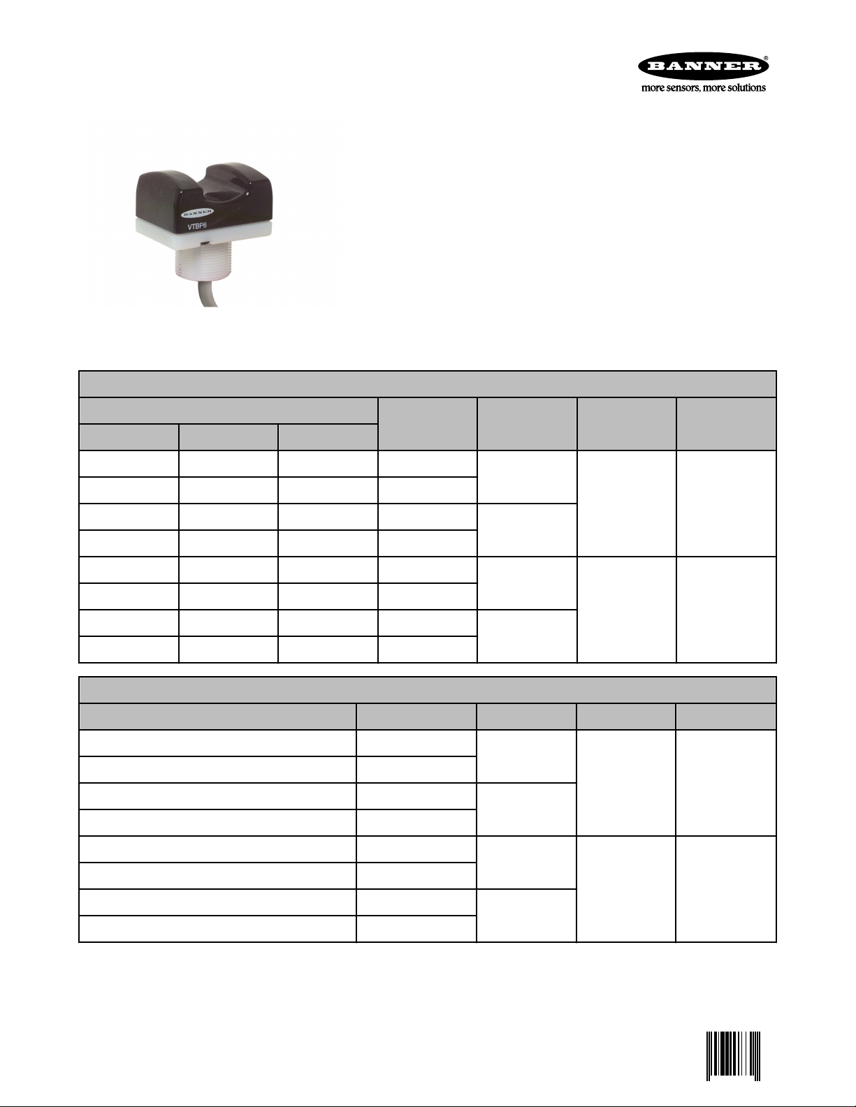
One-Color Job Light Models
Job Light Color
Green Red Blue
VTBN6 VTBN6R VTBN6B 2 m 4-wire cable
VTBN6Q VTBN6RQ VTBN6BQ 4-pin Euro QD
VTBN6L VTBN6RL VTBN6BL 2 m 4-wire cable
VTBN6LQ VTBN6RLQ VTBN6BLQ 4-pin Euro QD
VTBP6 VTBP6R VTBP6B 2 m 4-wire cable
VTBP6Q VTBP6RQ VTBP6BQ 4-pin Euro QD
VTBP6L VTBP6RL VTBP6BL 2 m 4-wire cable
VTBP6LQ VTBP6RLQ VTBP6BLQ 4-pin Euro QD
Two-Color Job Light Models
Green and Red (see Wiring) Cable* Upper Housing Output Type Job Light Input
VTBN6GR 2 m 5-wire cable
VTBN6GRQ 5-pin Euro QD
VTBN6GRL 2 m 5-wire cable
VTBN6GRLQ 5-pin Euro QD
Cable* Upper Housing Output Type Job Light Input
Polysulfone
NPN 0V dc
Polycarbonate
Polysulfone
PNP +10 to 30V dc
Polycarbonate
Polysulfone
NPN 0V dc
Polycarbonate
VTBP6GR 2 m 5-wire cable
Polysulfone
VTBP6GRQ 5-pin Euro QD
PNP +10 to 30V dc
VTBP6GRL 2 m 5-wire cable
Polycarbonate
VTBP6GRLQ 5-pin Euro QD
Standard 2 m (6.5 ft) cable models are listed. To order the 9 m (30 ft) cable model, add suffix "W/30" to the cabled model number. (For
example, VTBN6 W/30.) Models with a QD connector require a mating cable. (See Quick Disconnect (QD) Cables on page 5).
P/N 067570 Rev. C 5/10/2013
Page 2
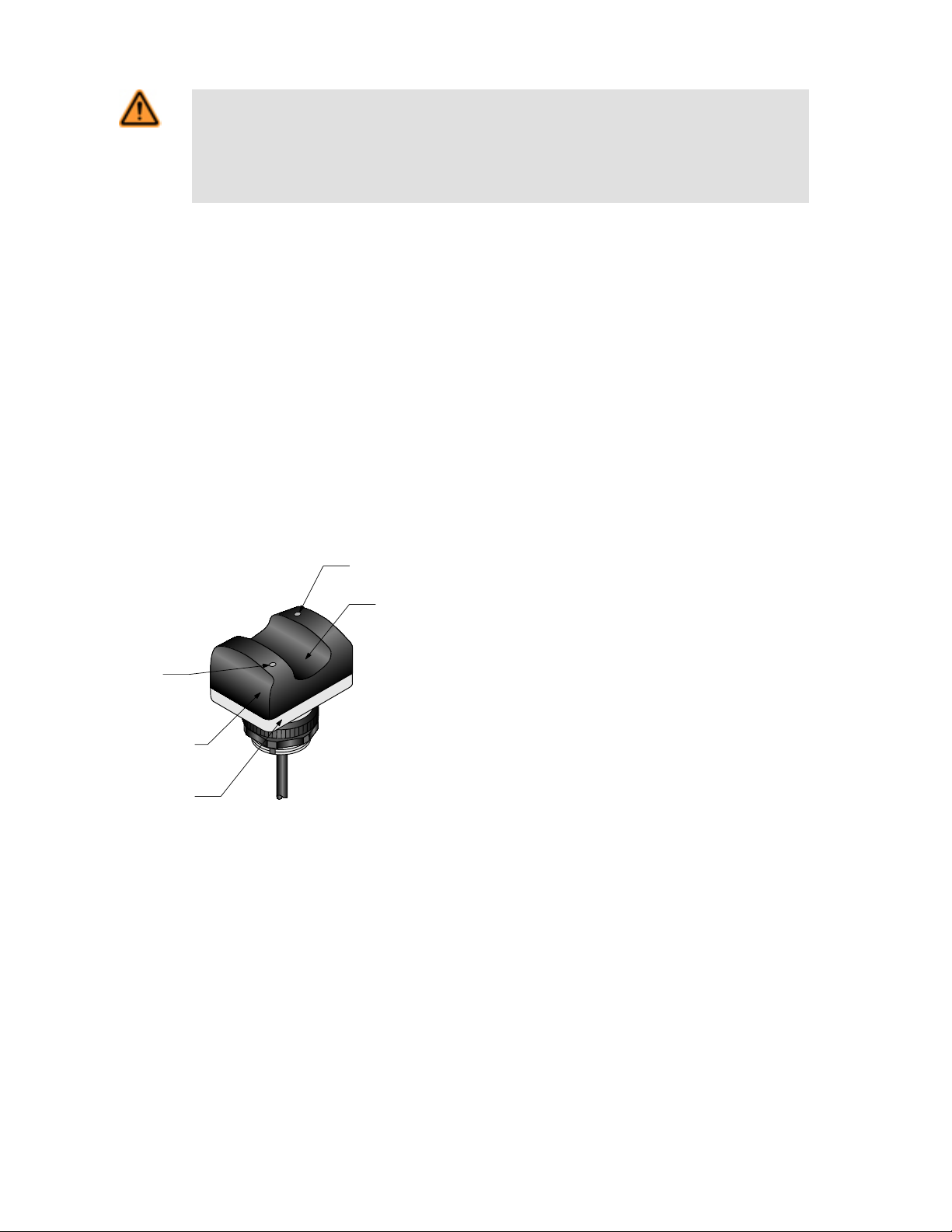
Black Polysulfone
or Red Polycarbonate
Translucent White
Polycarbonate
Base/Job Light
Output
Conducting
LED
Power ON/OFF
LED
Switch
"Touch Area"
VTB Pick-to-Light Optical Touch Button
WARNING: Not To Be Used for Personnel Protection
Never use this device as a sensing device for personnel protection. Doing so could lead to serious
injury or death. This device does not include the self-checking redundant circuitry necessary to allow its
use in personnel safety applications. A sensor failure or malfunction can cause either an energized or deenergized sensor output condition.
Overview
Banner VTB Series touch buttons are ergonomically designed to eliminate the hand, wrist, and arm stresses associated with mechanical
push buttons. They require absolutely no physical pressure to operate. LED indicators light when power is on and outputs are activated.
The interfaces to a system controller, which is pre-programmed for a specific sequence of tasks. Mounted in or near each bin in an
assembler’s work station, the sensor job light signals the assembler which bins contain items to be picked in a given operation and in
what order they should be picked.
As the assembler takes a part in sequence , then reaches a finger into the yoke of the corresponding Touch Button, the sensor senses
that the part was removed and it sends an output signal to the controller. The controller then verifies if the correct part was taken and may
respond by turning that job light OFF, activating the job light of the next bin in the sequence.
All models are immune to EMI, RFI, and ambient light interference. VTBs have either a black polysulfone or red polycarbonate upper
housing (depending on model) and a translucent white polycarbonate base. Environmental considerations for use of the two upper housing types differ; see specifications. The entire base section lights to provide a bright job light where a task is to be performed. The 30 mm
threaded base on all models provides easy mounting.
Indicators
Power ON/OFF (red):
Steady ON when power is applied
Output Conducting (red):
Steady ON when button is activated
OFF when button is not activated
Job Light:
Steady ON or flashing* when a task is to be performed
* Flashing job light is dependent on wiring. Color is dependent
on model and wiring.
2 www.bannerengineering.com - tel: 763-544-3164 P/N 067570 Rev. C
Page 3
bn
bu
-
+
bk
wh
12-30V dc
Job Light Enable
0V dc
Load
bn
bu
-
+
bk
wh
12-30V dc
Job Light Enable
+10-30V dc
Load
bn
bu
-
+
bk
wh
gy
12-30V dc
Green Job Light Enable — 0V dc
Red Job Light Enable — 0V dc
Load
bn
bu
-
+
bk
wh
12-30V dc
Job Light Enable
+10-30V dc
Load
bn
bu
-
+
bk
wh
12-30V dc
Job Light Enable
0V dc
Load
bn
bu
-
+
bk
wh
gy
12-30V dc
Green Job Light Enable — +10-30V dc
Red Job Light Enable — +10-30V dc
Load
2
3
4
1
2
3
4
1
5
VTB Pick-to-Light Optical Touch Button
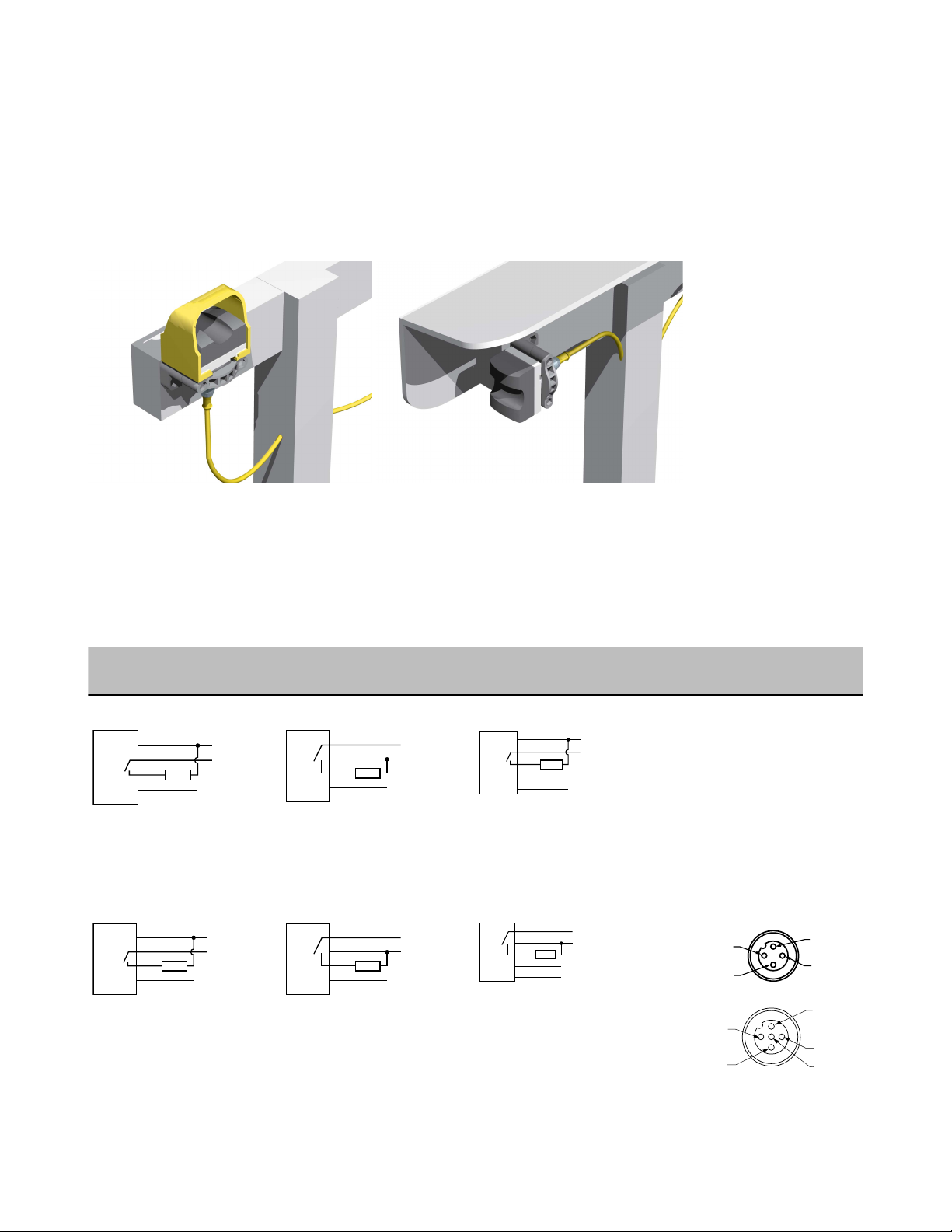
Installation
Consider ergonomic principles to avoid unnecessary fatigue in the installation of the hand controls. Install the touch buttons at a height
and in a location that will be comfortable for the user.
The following figure shows two methods for mounting the touch buttons, to prevent accidental switch actuation. When mounting them on
top of the control bar, the protective field covers should be in place, as shown; or for added protection, mount the touch buttons sideways
under and/or behind a protective hood, rather than on top of the bar, without using the field covers. This side mount prevents an object
from being left in the path of the beam. In addition, shields, covers, rings, collars, dividers, or similar protection may be used to prevent
accidental switch actuation.
Figure 1. Protect VTB touch buttons to prevent defeat or inadvertent actuation
Wiring
Single-color models may be wired for either a solid or flashing job light. The wiring of two-color models determines the job light. Color
flashing job light is not available. Cabled model wiring shown. Cabled and QD model wiring is functionally identical.
• For solid color, use the standard wiring diagram.
• For flashing (2 Hz), use the alternate wiring diagrams.
One-Color Job Light, NPN
(Sinking) Output Models
Solid Job Light Solid Job Light NPN (Sinking) Output Models
Flashing Job Light Flashing Job Light PNP (Sourcing) Output Models Pinouts
One-Color Job Light, PNP
(Sourcing) Output Models
Two-Color Job Light Models Wiring Key
1 = Brown
2 = Blue
3 = Black
4 = White
5 = Gray
6 = Load
7 = Job light enable
8 = Green job light
9 = Red job light
P/N 067570 Rev. C www.bannerengineering.com - tel: 763-544-3164 3
Page 4

VTB Pick-to-Light Optical Touch Button
Specifications
Supply Voltage and Current
One-color job light models: Less than 120 mA max current @ 12V dc and less than 70 mA max current @
30V dc (exclusive of load)
Two-color job light models: Less than 67 mA max current @ 12V dc; less than 40 mA max current @ 24V
dc; and less than 35 mA max current @ 30V dc (exclusive of load)
Supply Protection Circuitry
Protected against transient voltages (fast-transient and
over-voltage) and reverse polarity
Output Configuration
1 current sinking (NPN) open collector transistor or 1
current sourcing (PNP) open collector transistor, depending on model
Output Rating
Max. load: 150 mA
On-state saturation voltage: < 1.5V @ 150 mA
Off-state leakage current: < 10 μA
Output Protection Circuitry
All models protected against false pulse on power-up
(outputs held OFF for 1 second at power-up), overload
and short-circuits.
Output Response Time
100 milliseconds ON/OFF
Indicators
2 green LED indicators: Power ON and Output Conducting
Base lights green, red or blue (depending on model
and hookup) as a job light when input line is enabled.
One-color models may be wired for flashing, rather
than solid color operation.
Connections
PVC-jacketed 2 m (6.5') cables or 4-pin Euro-style QD
fitting, depending on model; integral 9 m (30') cables
are also available. Accessory QD cables required for
QD models.
Ambient Light Immunity
Up to 120,000 lux (direct sunlight)
EMI/RFI Immunity
Immune to EMI and RFI noise sources, per IEC
947-5-2
Environmental Rating
Meets NEMA standards 1, 3, 4, 4X, 12 and 13; IEC
IP66
Construction
Totally encapsulated, non-metallic enclosure. Black
polysulfone or red polycarbonate upper housing (see
Application Note below); translucent white polycarbonate base. Electronics fully epoxy-encapsulated.
Operating Conditions
–20° to +50° C (–4° to +122° F)
90% @ +55º C max. relative humidity (non-condens-
ing)
Application Notes
Environmental considerations for models with polysulfone upper housings: The polysulfone upper housing
will become brittle with prolonged exposure to outdoor
sunlight. Window glass effectively filters longer wavelength ultraviolet light and provides excellent protection
from sunlight. Avoid contact with strong alkalis. Clean
periodically using mild soap solution and a soft cloth.
Environmental considerations for models with polycarbonate upper housings: Avoid prolonged exposure to
hot water and moist high-temperature environments
above 66° C (150° F). Avoid contact with aromatic hydrocarbons (such as xylene and toluene), halogenated
hydrocarbons and strong alkalis. Clean periodically using mild soap solution and a soft cloth.
Certifications
4 www.bannerengineering.com - tel: 763-544-3164 P/N 067570 Rev. C
Page 5

max. torque 4.5 Nm (40 lbf in)
59.9 mm
(2.36")
27.9 mm
(1.10")
43.2 mm
(1.70")
35.0 mm
(1.38")
22.1 mm
(0.87")
15.2 mm
(0.60")
22.1 mm
(0.87")
M30 External Threads
Jam Nut, Lock Ring, and
Seal Washers are Supplied
NPSM
Internal Threads
VTBP6 VTBP6
44 Typ.
ø 14.5
M12 x 1
2
3
4
1
VTB Pick-to-Light Optical Touch Button
Dimensions
Accessories
Quick Disconnect (QD) Cables
Use the 4-pin Euro-style cordsets with the one-color job light models.
4-Pin Threaded M12/Euro-Style Cordsets
Model Length Style Dimensions Pinout
MQDC-406 1.83 m (6 ft)
MQDC-415 4.57 m (15 ft)
MQDC-430 9.14 m (30 ft)
MQDC-450 15.2 m (50 ft)
P/N 067570 Rev. C www.bannerengineering.com - tel: 763-544-3164 5
Straight
1 = Brown
2 = White
3 = Blue
4 = Black
Page 6

32 Typ.
[1.26"]
30 Typ.
[1.18"]
ø 14.5 [0.57"]
M12 x 1
44 Typ.
ø 14.5
M12 x 1
2
3
4
1
5
32 Typ.
[1.26"]
30 Typ.
[1.18"]
ø 14.5 [0.57"]
M12 x 1
45
61
69
A
B
C
70
57
A
B
C
57
VTB Pick-to-Light Optical Touch Button
4-Pin Threaded M12/Euro-Style Cordsets
Model Length Style Dimensions Pinout
MQDC-406RA 1.83 m (6 ft)
MQDC-415RA 4.57 m (15 ft)
MQDC-430RA 9.14 m (30 ft)
Right-Angle
MQDC-450RA 15.2 m (50 ft)
Use the 5-pin Euro-style cordsets with the two-color job light models.
5-Pin Threaded M12/Euro-Style Cordsets (Single Ended)
Model Length Style Dimensions Pinout (Female)
MQDC1-501.5 0.50 m (1.5 ft)
MQDC1-506 1.83 m (6 ft)
Straight
MQDC1-515 4.57 m (15 ft)
MQDC1-530 9.14 m (30 ft)
MQDC1-506RA 1.83 m (6 ft)
1 = Brown
2 = White
3 = Blue
MQDC1-515RA 4.57 m (15 ft)
4 = Black
5 = Gray
Right-Angle
MQDC1-530RA 9.14 m (30 ft)
Brackets
SMB30A
• Right-angle bracket with
curved slot for versatile
orientation
• Clearance for M6 (¼ in)
hardware
• Mounting hole for 30 mm
sensor
• 12-ga. stainless steel
Hole center spacing: A to B=40
Hole size: A=ø 6.3, B= 27.1 x 6.3, C=ø 30.5
6 www.bannerengineering.com - tel: 763-544-3164 P/N 067570 Rev. C
SMB30MM
• 12-ga. stainless steel
bracket with curved
mounting slots for versatile
orientation
• Clearance for M6 (¼ in)
hardware
• Mounting hole for 30 mm
sensor
Hole center spacing: A = 51, A to B = 25.4
Hole size: A = 42.6 x 7, B = ø 6.4, C = ø 30.1
Page 7

45
93
A
C
B
53
48
45
A
C
B
67
58
29
B
A
A
B
68.9
36.3
83.2
OTC Series
Field Cover
51.0 mm
(2.0")
69.0 mm
(2.7")
74.0 mm
(2.9")
VTB Pick-to-Light Optical Touch Button
SMBAMS30P
• Flat SMBAMS series
bracket
• 30 mm hole for mounting
sensors
• Articulation slots for 90°+
rotation
• 12-ga. 300 series stainless
steel
Hole center spacing: A=26.0, A to B=13.0
Hole size: A=26.8 x 7.0, B=ø 6.5, C=ø 31.0
SMB30SC
• Swivel bracket with 30 mm
mounting hole for sensor
• Black reinforced thermoplastic polyester
• Stainless steel mounting
and swivel locking hardware included
Hole center spacing: A=ø 50.8
Hole size: A=ø 7.0, B=ø 30.0
SMBAMS30RA
• Right-angle SMBAMS series bracket
• 30 mm hole for mounting
sensors
• Articulation slots for 90°+
rotation
• 12-ga. (2.6 mm) cold-rolled steel
Hole center spacing: A=26.0, A to B=13.0
Hole size: A=26.8 x 7.0, B=ø 6.5, C=ø 31.0
SMB30FA
• Swivel bracket with tilt and
pan movement for precise
adjustment
• Mounting hole for 30 mm
sensor
• 12-ga. 304 stainless steel
• Easy sensor mounting to
extrude rail T-slot
• Metric and inch size bolt
available
Bolt thread: SMB30FA, A= 3/8 - 16 x 2 in; SMB30FAM10, A=
M10 - 1.5 x 50
Hole size: B= ø 30.1
Field Covers
Field covers are designed to prevent inadvertent activation of optical touch buttons by objects that accidentally block the sensing beam.
Field covers are constructed of rugged polypropylene and are highly resistant to abrasion and to damage by most chemicals. A variety of
colors is available, allowing color-coding when multiple touch buttons are used. Note that when a field cover is used, it also blocks a
portion of the job light.
Model Description
OTC-1-BK Black cover
OTC-1-GN Green cover
OTC-1-RD Red cover
OTC-1-YW Yellow cover
Banner Engineering Corp Limited Warranty
Banner Engineering Corp. warrants its products to be free from defects in material and workmanship for one year following the date of
shipment. Banner Engineering Corp. will repair or replace, free of charge, any product of its manufacture which, at the time it is returned
to the factory, is found to have been defective during the warranty period. This warranty does not cover damage or liability for misuse,
abuse, or the improper application or installation of the Banner product.
P/N 067570 Rev. C www.bannerengineering.com - tel: 763-544-3164 7
Page 8

VTB Pick-to-Light Optical Touch Button
THIS LIMITED WARRANTY IS EXCLUSIVE AND IN LIEU OF ALL OTHER WARRANTIES WHETHER EXPRESS OR IMPLIED (INCLUDING, WITHOUT LIMITATION, ANY WARRANTY OF MERCHANTABILITY OR FITNESS FOR A PARTICULAR PURPOSE), AND
WHETHER ARISING UNDER COURSE OF PERFORMANCE, COURSE OF DEALING OR TRADE USAGE.
This Warranty is exclusive and limited to repair or, at the discretion of Banner Engineering Corp., replacement. IN NO EVENT SHALL
BANNER ENGINEERING CORP. BE LIABLE TO BUYER OR ANY OTHER PERSON OR ENTITY FOR ANY EXTRA COSTS, EXPENSES, LOSSES, LOSS OF PROFITS, OR ANY INCIDENTAL, CONSEQUENTIAL OR SPECIAL DAMAGES RESULTING FROM ANY
PRODUCT DEFECT OR FROM THE USE OR INABILITY TO USE THE PRODUCT, WHETHER ARISING IN CONTRACT OR WARRANTY, STATUTE, TORT, STRICT LIABILITY, NEGLIGENCE, OR OTHERWISE.
Banner Engineering Corp. reserves the right to change, modify or improve the design of the product without assuming any obligations or
liabilities relating to any product previously manufactured by Banner Engineering Corp.
www.bannerengineering.com - tel: 763-544-3164
 Loading...