

Page 1

VS8 Sensor Series
201958
Instruction Manual
Original Instructions
201958 Rev. B
31 May 2018
©
Banner Engineering Corp. All rights reserved
Page 2

VS8 Sensor Series
Contents
1 Product Description .................................................................................................................................................3
1.1 Models ...............................................................................................................................................................................3
1.2 Features .............................................................................................................................................................................4
2 Sensor Installation .................................................................................................................................................. 5
2.1 Wiring Diagrams ................................................................................................................................................................ 5
3 Sensor Configuration ..............................................................................................................................................6
3.1 Remote Configuration – 4-Pin Models .............................................................................................................................. 6
3.2 Two-Point Static Background Suppression ......................................................................................................................6
3.3 One-Point Static Background Suppression ...................................................................................................................... 7
3.4 Dynamic Background Suppression ....................................................................................................................................8
3.5 Two-Point Static Opposed and
3.6 Dynamic Opposed and Retroreflective ........................................................................................................................... 10
3.7 Select Light Operate/Dark Operate – 4-Pin Models ........................................................................................................11
Specifications ....................................................................................................................................................... 12
4
4.1 Dimensions ......................................................................................................................................................................12
5 Performance Curves .............................................................................................................................................13
5.1 Beam Spot Sizes .............................................................................................................................................................13
6 Accessories ........................................................................................................................................................... 14
6.1 Cordsets for VS8 Models with
6.2 Cordsets for VS8 Models with Suffix Q3 .........................................................................................................................14
6.3 Cordsets for VS8 Models with Suffix Q5 .........................................................................................................................14
6.4 Brackets .......................................................................................................................................................................... 15
Retroreflectors .................................................................................................................................................................16
6.5
7 Banner Engineering Corp. Limited Warranty ........................................................................................................17
Retroreflective ................................................................................................................ 9
Suffix Q ...........................................................................................................................14
Page 3

VS8 Sensor Series
1 Product Description
• Miniature sensor for installation in the smallest of spaces
• Red laser models provide bright, precise laser light spot for optimum small part detection
• High switching frequency for detection in even the fastest processes
• User-friendly operation using electronic push button or remote input provides reliable and precise
detection
• Red laser, Red LED, and Blue LED types available to match sensing beam to application
• Robust, glass-fiber-reinforced plastic housing
• PNP or NPN output, depending on model
WARNING: Not To Be Used for Personnel Protection
Never use this device as a sensing device for personnel protection. Doing so could lead to serious injury
or death. This device does not include the self-checking redundant circuitry necessary to allow its use in
personnel safety applications. A sensor failure or malfunction can cause either an energized or deenergized sensor output condition.
1.1 Models
Opposed Models
Model Sensing Mode Range Output Connection
VS8LEJ
VS8LEJQ –
VS8EAPR
VS8EANR NPN
VS8EAPRQ PNP
VS8EANRQ NPN
Red Laser Emitter
with Beam Inhibit
0 m to 3 m
(0 in to 9.8 ft)
Receiver
– 2 m (6.5 ft) unterminated 4-wire PUR cable
200 mm (7.8 in) PUR cable with a 4-pin
M8/Pico-style male quick disconnect (QD)
PNP
2 m (6.5 ft) unterminated 4-wire PUR cable
200 mm (7.8 in) PUR cable with a 4-pin
M8/Pico-style male quick disconnect (QD)
Retroreflective Models
Model Sensing Mode Range Output Connection
VS8EAPLP
VS8EANLP NPN
VS8EAPLPQ PNP
VS8EANLPQ NPN
VS8EAPLLP
VS8EANLLP NPN
VS8EAPLLPQ PNP
VS8EANLLPQ NPN
www.bannerengineering.com - Tel: +1.763.544.3164 3
Red LED Retro
Reflective
Red Laser Retro
Reflective
0.1 m to 1.6 m
(3.9 in to 62.9 in)
with BRT-2X2
0.1 m to 2 m
(3.9 in to 78.7 in)
with
BRT-51X51BM
PNP
2 m (6.5 ft) unterminated 4-wire PUR cable
200 mm (7.8 in) PUR cable with a 4-pin
M8/Pico-style male quick disconnect (QD)
PNP
2 m (6.5 ft) unterminated 4-wire PUR cable
200 mm (7.8 in) PUR cable with a 4-pin
M8/Pico-style male quick disconnect (QD)
Page 4

1
2
3
4
VS8 Sensor Series
Background Suppression Models
Model
VS8EAPAF70
VS8EANAF70 NPN
1
Sensing Mode Range Output
Red LED, Adjustable
Background Suppression
5 mm to 70 mm
(0.2 in to 2.8 in)
PNP
VS8EAPLAF70
VS8EANLAF70 NPN
VS8APFF30B
VS8ANFF30B NPN
VS8APFF15
VS8ANFF15 NPN
VS8APFF30
VS8ANFF30 NPN
VS8APFF50
VS8ANFF50 NPN
Red Laser, Adjustable
Background Suppression
Blue LED, Fixed 30 mm
Background Suppression
Red LED, Fixed 15 mm
Background Suppression
Red LED, Fixed 30 mm
Background Suppression
Red LED, Fixed 50 mm
Background Suppression
6 mm to 70 mm
(0.24 in to 2.8 in)
2 mm to 30 mm
(0.08 in to 1.18 in)
2 mm to 15 mm
(0.08 in to 0.59 in)
2 mm to 30 mm
(0.08 in to 1.18 in)
2 mm to 50 mm
(0.08 in to 1.97 in)
PNP
PNP
PNP
PNP
PNP
1.2 Features
Features
1. Green Indicator
2. Amber Indicator
3. TEACH Button - Laser Adjustable Field (LAF),
Adjustable Field (AF), Polar Retro (LP), and Receiver (R)
Models
4. Optical Window
2 m (6.5 ft) unterminated
4-wire PUR cable
Figure 1. VS8 Sensor Features
1
• To order the 200 mm (7.8 in) PUR cable model with a 4-pin M8/Pico-style quick disconnect, add suffix "Q" to the model number. For
example, VS8EAPAF70Q. Only available for AF and LAF models.
• To order the 200 mm (7.8 in) PUR cable model with a 3-pin M8/Pico-style quick disconnect, add suffix "Q3" to the model number. For
example, VS8APFF15Q3. Only available for FF models.
• To order the 200 mm (7.8 in) PUR cable model with a 4-pin M12/Euro-style quick disconnect, add suffix "Q5" to the model number. For
example, VS8EAPAF70Q5. Only available for AF and LAF models.
4 www.bannerengineering.com - Tel: +1.763.544.3164
Page 5

10-30V dc
–
+
3
1
4
Load
10-30V dc
–
+
3
1
4
Load
1
3
4
2
10-30V dc
–
+
Remote
Input
Load
1
3
4
2
10-30V dc
–
+
Remote
Input
Load
10-30V dc
Beam
Inhibit
1
3
4
2
no connection
VS8 Sensor Series
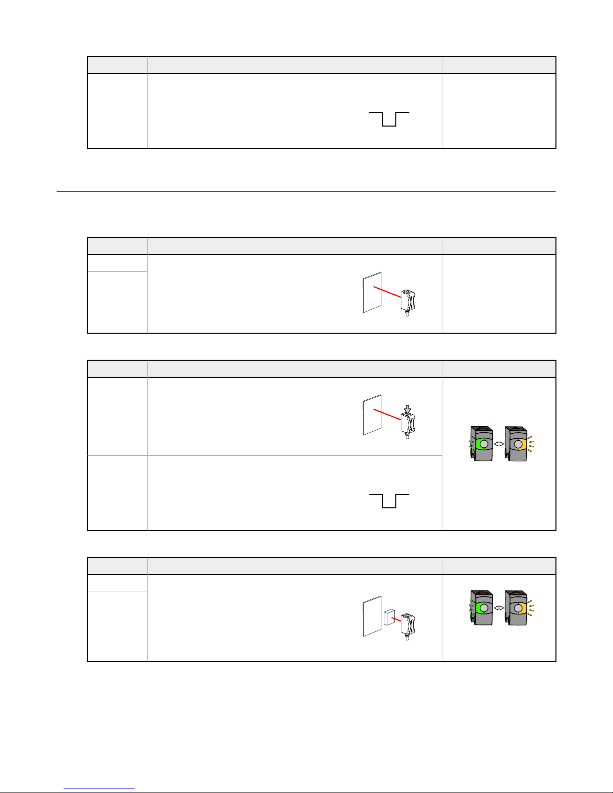
2 Sensor Installation
Install the sensor so the object to be detected
moves horizontally to the sensor.
Figure 2. VS8 Sensor Installation
2.1 Wiring Diagrams
3-Pin NPN Models
4-Pin NPN Models
3-Pin PNP Models
4-Pin PNP Models
Key
Note: All 4-pin and cabled models have a remote input on the white wire (pin-2).
1. Brown
2. White
3. Blue
4. Black
Opposed Mode Emitters
www.bannerengineering.com - Tel: +1.763.544.3164 5
Page 6

> 3 s
BOTH LEDs FLASHING
ALTERNATING
T
> 3 s
BOTH LEDs FLASHING
ALTERNATING
VS8 Sensor Series
3 Sensor Configuration
•
• 3-pin fixed field and opposed mode emitter models require no user adjustments.
• The remote input wire (pin-2/white wire) is used to select light or dark operate or perform the desired TEACH
3.1 Remote Configuration – 4-Pin Models
The remote input wire (pin-2/white wire) is used to select light or dark operate, or perform the desired TEACH method.
Closing and opening times for the remote input wire correspond to the indicated press/hold durations of the push button.
3.2 Two-Point Static Background Suppression
Two-point TEACH sets a single switch point. The sensor sets the switch point between two taught target distances, relative
to the shifted origin location.
1. Present the target.
™
Expert
either the sealed push button or the remote input wire.
method. Pulse durations for the remote input wire correspond to the indicated press durations of the push button.
4-pin background suppression, retroreflective, and opposed mode receiver models are configurable using
Method Action Result
Push Button
Remote
Input
2. Start TEACH mode.
Method Action Result
Push Button Press and hold push button > 3 seconds.
Remote
Input
3. Present the background or second target.
Method
Push Button
Present the first target. The sensor-to-target
distance must be within the sensor's range.
Pulse remote input wire > 3 seconds.
Action Result
N/A
Present the background or second target.
Remote
Input
4. Configure the sensor.
6 www.bannerengineering.com - Tel: +1.763.544.3164
The sensor-to-target distance must be within
the sensor's range.
Page 7

> 1 s
T
> 1 s
> 3 s
BOTH LEDs FLASHING
ALTERNATING
T
> 3 s
> 1 s
VS8 Sensor Series
Method Action Result
Push Button Press push button > 1 second.
Sensor returns to normal
operation.
Remote
Input
Pulse remote input wire > 1 second.
3.3 One-Point Static Background Suppression
One-point TEACH sets a single switch point. The sensor sets the switch point just behind the taught target distance.
1. Present the target.
Method Action Result
Push Button
Present the target. The sensor-to-target
Remote
distance must be within the sensor's range.
Input
2. Start TEACH mode.
N/A
Method Action Result
Push Button Press and hold push button > 3 seconds.
Remote
Input
Pulse remote input wire > 3 seconds.
3. Configure the sensor.
Method
Action Result
Push Button Press push button > 1 second.
Sensor returns to normal
operation.
www.bannerengineering.com - Tel: +1.763.544.3164 7
Page 8

T
> 1 s
> 3 s
BOTH LEDs FLASHING
ALTERNATING
T
> 3 s
> 1 cycle
VS8 Sensor Series
Method Action Result
Remote
Input
Pulse remote input wire > 1 second.
3.4 Dynamic Background Suppression
Dynamic TEACH sets a single switch point during machine run conditions. Dynamic TEACH is recommended for
applications where a machine or process may not be stopped for teaching. The sensor takes multiple samples and the
switch point is set just behind the farthest taught target distance, accounting for a static background.
1. Present the target.
Method Action Result
Push Button
Present the first target. The sensor-to-target
Remote
distance must be within the sensor's range.
Input
2. Start TEACH mode.
Method Action Result
N/A
Push Button Press and hold push button > 3 seconds.
Remote
Input
Pulse remote input wire > 3 seconds.
3. Configure the sensor.
Method Action Result
Push Button
Press and hold push button > 1 cycle of
operation.
Sensor returns to normal
operation.
8 www.bannerengineering.com - Tel: +1.763.544.3164
Page 9
T
> 1 cycle
> 3 s
BOTH LEDs FLASHING
ALTERNATING
T
> 3 s
BOTH LEDs FLASHING
ALTERNATING
VS8 Sensor Series
Method Action Result
Remote
Input
Pulse remote input wire > 1 cycle of
operation.
3.5 Two-Point Static Opposed and Retroreflective
Two-point TEACH for Opposed and Retroreflective modes sets a single switching level. The sensor sets the switching level
between the blocked and unblocked conditions.
1. Align the sensor.
Method Action Result
Push Button
Align the emitter/receiver or sensor/
Remote
Input
retroreflector. The beam path should not be
blocked.
2. Start TEACH mode.
Method Action Result
N/A
Push Button Press and hold push button > 3 seconds.
Remote
Input
Pulse remote input wire > 3 seconds.
3. Present the target.
Method Action Result
Push Button
Present the target. The beam path should be
Remote
blocked by the target.
Input
4. Configure the sensor.
www.bannerengineering.com - Tel: +1.763.544.3164 9
Page 10

> 1 s
T
> 1 s
> 3 s
BOTH LEDs FLASHING
ALTERNATING
T
> 3 s
VS8 Sensor Series
Method Action Result
Push Button Press and hold push button > 1 second.
Remote
Input
Pulse remote input wire > 1 second.
Sensor returns to normal
operation.
3.6 Dynamic Opposed and Retroreflective
Dynamic TEACH for Opposed and Retroreflective modes sets a single switching level during machine run conditions.
Dynamic TEACH is recommended for applications where a machine or process may not be stopped for teaching. The
sensor takes multiple samples and the switching level is set between the blocked and unblocked conditions.
1. Present the target.
Method Action Result
Push Button
Remote
Input
Present the target. The beam path should be
blocked by the target.
N/A
2. Start TEACH mode.
Method Action Result
Push Button Press and hold push button > 3 seconds.
Remote
Input
Pulse remote input wire > 3 seconds.
3. Configure the sensor.
10 www.bannerengineering.com - Tel: +1.763.544.3164
Page 11

> 1 cycle
T
> 1 cycle
> 10 s
GREEN LED FLASHING
T
4-1000 ms
GREEN LED FLASHING
AMBER LED ON
GREEN LED FLASHING
AMBER LED OFF
VS8 Sensor Series
Method Action Result
Push Button
Remote
Input
Press and hold push button > 1 cycle of
operation.
Pulse remote input wire > 1 cycle of
operation.
Sensor returns to normal
operation.
3.7 Select Light Operate/Dark Operate – 4-Pin Models
Change the sensor operation to light operate or dark operate for the desired application. Use either the button or the remote
input wire procedure to configure the sensor.
Method Action Result
Push
Button
Remote
Input
Wire
Press and hold the button for longer
than 10 seconds.
Press the button until the desired
operation is selected, then release the
button and wait 10 seconds.
Pulse the remote input wire to + V dc for
longer than 10 seconds.
Pulse the remote input wire to + V dc for
4 to 1000 ms until the desired operation
is selected and wait 10 seconds.
1. The green LED flashes
to show that the sensor
is in LO/DO select mode.
2. The amber LED indicates the selected
operation mode.
Light Operate
www.bannerengineering.com - Tel: +1.763.544.3164 11
Dark Operate
3. The sensor is configured and returns to
normal operation.
Page 12
5.5
8
Receiver
Emitter
ø3.3
14.6
2.8
18.3
3.3
ø4.9
ø2.6
8
4.6
21.1
Teach-in
LED 2
LED 1
9.6
6.8
8.2
ø3.3
20.6
15
VS8 Sensor Series
4 Specifications
Supply Voltage and Current
LED models: 10 V dc to 30 V dc (10% max. ripple) at less than 20 mA,
exclusive of load
Laser models: 10 V dc to 30 V dc (10% max. ripple) at less than 12 mA,
exclusive of load
Supply Protection Circuitry
Protected against reverse polarity and short-circuit
Output Protection Circuitry
Protected against output short-circuit, continuous overload, and false
pulse on power-up
Output Configuration
Retroreflective and Background Suppression Models: Single PNP or
NPN on pin 4 (black wire) with remote input on pin 2 (white wire)
Opposed Mode Receivers only: Single PNP or NPN on pin 4 (black wire)
with remote input on pin 2 (white wire)
Output Response Time
500 µs
Output Rating
50 mA
Switching Frequency
≤ 1000 Hz
Delay Before Power-Up
< 300 ms
Laser Classifications
All Models: Class 1; wavelength: 655 nm; frequency: 5 kHz; pulse
duration: 3.2 µs; limit value pulse: ≤ 2.3 mW. Reference IEC
60825-1:2001, Section 8.2.
All Models: Complies with 21 CFR 1040.10 and 1040.11 except for
deviations pursuant to laser Notice No. 50 dated June 24, 2007.
Blue LED Models: Risk Group 2; possibly hazardous optical radiation
emitted from this product. Do not stare at the operating lamp. May be
harmful to the eyes. (EN62471)
Opposed Mode Model Adjustments
Push button teach input (Receivers)
Remote wire teach input (Receivers)
Remote wire beam inhibit (Emitters)
Indicators
2 LED indicators on sensor top
Green on: Power on
Amber on: Output conducting
Emitter LED Wavelength
Red LED models: 650 nm
Blue LED models: 450 nm
Laser models: 655 nm
Effective Beam
5.5 mm
This can be adjusted without an aperture by teaching the sensor
Connections
2 m (6.5 ft) unterminated 4-wire PUR cable or 200 mm (7.8 in) PUR
cable with a 3- or 4-pin M8/Pico-style or 4-pin M12/Euro-style male
quick disconnect, depending on model
Models ending in
recognized cordset R/C (CYJV2)
Search p/n 201958 at
Instruction Manual for more information on cordsets
Construction
Housing, cable: PUR
Front screen: PMMA
Operating Conditions
LED models: –20 °C to +60 °C (–4 °F to +140 °F)
Laser models: –20 °C to +50 °C (–4 °F to +122 °F)
Storage Temperature: –20 °C to +80 °C (–4 °F to +176 °F)
UL Operating Temperature: –20 °C to +30 °C (–4 °F to +86 °F)
Chemical Compatibility
ECOLAB® certified (2 m cabled models only)
Environmental Rating
IEC IP67
Certifications
suffix "Q", "Q3", or "Q5" must be used with a UL
www.bannerengineering.com
to view the
4.1 Dimensions
All measurements are listed in millimeters [inches], unless noted otherwise.
12 www.bannerengineering.com - Tel: +1.763.544.3164
Sensor with Bracket (SMBVS8DT)
Page 13

Distance (m)
Size (mm)
0
0
5
10
15
20
25
30
1 2 3 4 5
horizontal (x)
vertical (y)
Distance (m)
Size (mm)
0
0
20
40
60
80
100
120
140
0.2 0.4 0.6 0.8 1 1.4 1.6
horizontal (x)
vertical (y)
1.2
Distance (m)
Size (mm)
0
0
2
4
6
8
10
12
14
16
0.5 1.0 1.5 2.0 2.5
horizontal (x)
vertical (y)
Distance (mm)
Size (mm)
0
0
1
2
3
4
5
6
10 20 30 40 50
horizontal (x)
vertical (y)
Distance (mm)
Size (mm)
0
0
1
2
3
4
5
6
10 20 30 40 50
horizontal (x)
vertical (y)
Distance (mm)
Size (mm)
horizontal (x)
vertical (y)
0
0
1
2
3
4
5
6
10 20 30 40 50 60 70
VS8 Sensor Series
5 Performance Curves
5.1 Beam Spot Sizes
Opposed Mode
Laser Retroreflective
Retroreflective
Fixed Field Background Suppression with Blue LED
Fixed Field Background Suppression
www.bannerengineering.com - Tel: +1.763.544.3164 13
Adjustable Field Background Suppression
Page 14

ø 9.5
35 Typ.
M8 x 1
4
3
1
2
ø 9.5
28 Typ.
20 Typ.
M8 x 1
ø 9.5
35 Typ.
M8 x 1
4
3
1
ø 9.5
28 Typ.
20 Typ.
M8 x 1
VS8 Sensor Series
6 Accessories
6.1 Cordsets for VS8 Models with
Suffix Q
All measurements are listed in millimeters, unless noted otherwise.
4-Pin Threaded M8/Pico-Style Cordsets
Model Length Style Dimensions Pinout (Female)
PKG4M-2 2 m (6.56 ft)
PKG4M-5 5 m (16.4 ft)
PKG4M-9 9 m (29.5 ft)
PKW4M-2 2 m (6.56 ft)
PKW4M-5 5 m (16.4 ft)
PKW4M-9 9 m (29.5 ft)
Straight
Right Angle
1 = Brown
2 = White
3 = Blue
4 = Black
6.2 Cordsets for VS8 Models with Suffix Q3
3-Pin Threaded M8/Pico-Style Cordsets
Model Length Style Dimensions Pinout (Female)
PKG3M-2 2 m (6.56 ft)
PKG3M-5 5 m (16.40 ft)
PKG3M-7 7 m (22.97 ft)
PKG3M-9 9 m (29.53 ft)
PKG3M-10 10 m (32.81 ft)
PKW3M-2 2 m (6.56 ft)
PKW3M-5 5 m (16.40 ft)
PKW3M-9 9 m (29.53 ft)
Straight
Right-Angle
1 = Brown
3 = Blue
4 = Black
6.3 Cordsets for VS8 Models with Suffix Q5
All measurements are listed in millimeters, unless noted otherwise.
4-Pin Threaded M12/Euro-Style Cordsets
Cable: PVC jacket, PUR (polyurethane) connector body, nickel-plated brass coupling nut
Conductors: 22 AWG, gold-plated contacts
Conductors: 22 AWG, gold-plated contacts
Voltage/Current Rating: 250 V ac/dc, 4.0 A
Temperature: –40 °C to +105 °C (–40 °F to +221 °F)
14 www.bannerengineering.com - Tel: +1.763.544.3164
Page 15

44 Typ.
ø 14.5
M12 x 1
2
3
4
1
14
Ø3.3
3 X
21
13
Ø3.3
2 X
8.2
15
21
11
34
34
Ø3.3
Ø3.2
11
34
34
Ø3.3
4 X
2 X
Ø3.2
VS8 Sensor Series
Environmental Rating: IP67/IP69K
4-Pin Threaded M12/Euro-Style Cordsets
Model Length Style Dimensions Pinout (Female)
MQDC-406 1.83 m (6 ft)
MQDC-415 4.57 m (15 ft)
MQDC-430 9.14 m (30 ft)
Straight
MQDC-450 15.2 m (50 ft)
1 = Brown
2 = White
3 = Blue
4 = Black
6.4 Brackets
SMBVS8RA
• Right-angle bracket
• 3.1 mm stainless steel
SMBQ12A
• Adjustable right-angle
bracket
• 20-ga. 300 series
stainless steel
Hole center spacing: A to B = 7.6
Hole size: A = 3.5 x 8.1, B=ø 3.2
SMBQ20FA
• Includes 3/8-16 X 2 in
Socket Head Cap Screw
(SHCS)
• 304 stainless steel
SMBVS8DT
• Dovetail clamp bracket
• Adjustable ± 10°
• Material: PBT
SMBQ12T
• Right-angle bracket
• 20-ga. 300 series
stainless steel
Hole center spacing: A to B = 7.6
Hole size: A = 3.5 x 8.1, B=ø 3.2
www.bannerengineering.com - Tel: +1.763.544.3164 15
Page 16

3.7
ø10
35 mm
(1.4)"
25 mm
(0.98")
Clearance
for M3
8.4 mm
(0.33")
42 mm
(1.7")
34 mm
(1.3")
11
11
3.7
60
18
40
2 x ø3.5
VS8 Sensor Series
6.5 Retroreflectors
BRT-10BM
• Round, acrylic target
•
Reflectivity Factor: 1.0
• Temperature: –20 °C to +60 °C (–
4 °F to +140 °F)
• Micro-prism geometry
• Size: 10 mm diameter
• Reflective area: ø10 mm
BRT-11X11M
• Square, acrylic target
•
Reflectivity Factor: 1.2
• Temperature: –20 °C to +60 °C (–4 °F
to +140 °F)
• Micro-prism geometry
• Approximate size: 11 mm × 11 mm
Note: For maximum adhesion of all tape products, surfaces must be clean.
Model Reflectivity Factor Maximum Temperature Size
BRT-TVHG-2X2 0.8 +60 °C (+140 °F) 50 × 50 mm
BRT-35X35BM
• Square, acrylic target
•
Reflectivity Factor: 1.2
• Temperature:
-20 °C to +60 °C
(-4 °F to +140 °F)
• Micro-prism geometry
• Approximate size:
35 mm × 35 mm
BRT-40X18A
• Rectangular, acrylic target
•
Reflectivity Factor: 1.0
• Temperature: –20 °C to +60 °C (–4 °F
to +140 °F)
• Approximate size: 18 mm × 50 mm
These are sealed micro-prism style pieces and may not be cut.
Model Reflectivity Factor Maximum Temperature Size
BRT-THG-2-100 0.7 +60 °C (+140 °F) 50 mm (2 in) wide, 2.5 m (100 in) long
16 www.bannerengineering.com - Tel: +1.763.544.3164
Page 17

VS8 Sensor Series
7 Banner Engineering Corp. Limited Warranty
Banner Engineering Corp. warrants its products to be free from defects in material and workmanship for one year following the date of shipment. Banner Engineering Corp. will
repair or replace, free of charge, any product of its manufacture which, at the time it is returned to the factory, is found to have been defective during the warranty period. This
warranty does not cover damage or liability for misuse, abuse, or the improper application or installation of the Banner product.
THIS LIMITED WARRANTY IS EXCLUSIVE AND IN LIEU OF ALL OTHER WARRANTIES WHETHER EXPRESS OR IMPLIED (INCLUDING, WITHOUT LIMITATION, ANY
WARRANTY OF MERCHANTABILITY OR FITNESS FOR A PARTICULAR PURPOSE), AND WHETHER ARISING UNDER COURSE OF PERFORMANCE, COURSE OF DEALING
OR TRADE USAGE.
This Warranty is exclusive and limited to repair or, at the discretion of Banner Engineering Corp., replacement. IN NO EVENT SHALL BANNER ENGINEERING CORP. BE
LIABLE TO BUYER OR ANY OTHER PERSON OR ENTITY FOR ANY EXTRA COSTS, EXPENSES, LOSSES, LOSS OF PROFITS, OR ANY INCIDENTAL, CONSEQUENTIAL OR
SPECIAL DAMAGES RESULTING FROM ANY PRODUCT DEFECT OR FROM THE USE OR INABILITY TO USE THE PRODUCT, WHETHER ARISING IN CONTRACT OR
WARRANTY, STATUTE, TORT, STRICT LIABILITY, NEGLIGENCE, OR OTHERWISE.
Banner Engineering Corp. reserves the right to change, modify or improve the design of the product without assuming any obligations or liabilities relating to any product
previously manufactured by Banner Engineering Corp. Any misuse, abuse, or improper application or installation of this product or use of the product for personal protection
applications when the product is
by Banner Engineering Corp will void the product warranties. All specifications published in this document are subject to change; Banner reserves the right to modify product
specifications or update documentation at any time. Specifications and product information in English supersede that which is provided in any other language. For the most
recent version of any documentation, refer to:
identified as not intended for such purposes will void the product warranty. Any modifications to this product without prior express approval
www.bannerengineering.com
.
www.bannerengineering.com - Tel: +1.763.544.3164 17
 Loading...