

Page 1
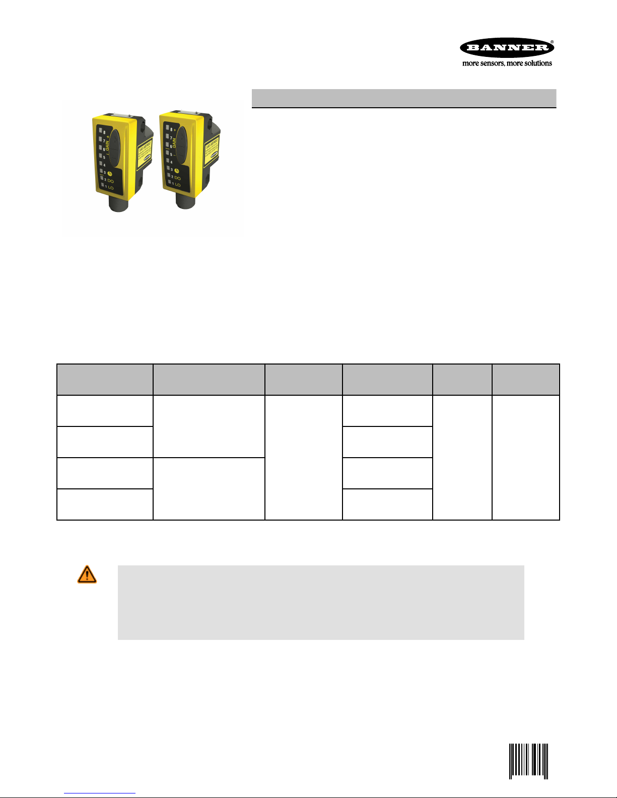
WORLD-BEAM QS30 LLP and LLPC
0 112355 5
Polarized Retroreflective Laser Sensors
• Visible class 1 laser with small, effective beam size
• Excellent optical performance throughout sensing range, even close up
• Easy push-button SET options: Maximum Excess Gain or Low-Contrast
SET, depending on model, plus Manual Adjust
• Easy-to-read operating status indicators, with 8-segment bargraph display
• Bipolar discrete outputs, PNP and NPN
• Selectable 30 millisecond OFF-delay
• Models available with 2 m or 9 m (6.5' or 30') cable or integral quick-disconnect
Excellent for applications where high sensing power and small beam size are important. Operates over sensing ranges typically accomplished only by conventional opposed-mode photoelectrics; uses a special filter to polarize the emitted light, filtering out unwanted reflections from shiny objects.
• Tough ABS housing rated IEC IP67; NEMA 6
• Compact housing, mounting versatility – popular 30 mm threaded nose or
side-mount
Features
Models
Model Range and Use Spot Size at Fo-
cus
Cable* Supply Output Type
QS30LLP
QS30LLPQ
QS30LLPC
QS30LLPCQ
* 9 m (30 ft) cables are available by adding suffix “W/30” to the model number of any cabled sensor (e.g., QS30LLP W/30). A model with
a QD connector requires a mating cable (see Quick-Disconnect Cables on page 10).
WARNING: Not To Be Used for Personnel Protection
Never use this product as a sensing device for personnel protection. Doing so could lead to serious
injury or death. This product does NOT include the self-checking redundant circuitry necessary to allow its
use in personnel safety applications. A sensor failure or malfunction can cause either an energized or deenergized sensor output condition.
0.2 to 18 m (0.67 ft to 60 ft)
Maximum Excess Gain SET
for Long-Range Applications
0.2 to 18 m (0.67 ft to 60 ft)
Low-Contrast SET for Small
Object Detection
Approx. 4 mm at
10 m (0.16 in at 33
ft)
2 m (6.5 ft) 5-wire Cable
Integral 5-pin Eurostyle QD
2 m (6.5 ft) 5-wire Cable
Integral 5-pin Eurostyle QD
10 to 30V dc
Bipolar NPN /
PNP
P/N 112355 Rev. C 12/18/2013
Page 2
1
10
100
1.0 m
3.3'
10 m
33'
100 m
330'
0.1 m
0.33'
1000
E
X
C
E
S
S
G
A
I
N
DISTANCE
with BRT-51X51BM
1
10
100
1.0 m
3.3'
10 m
33'
100 m
330'
0.1 m
0.33'
1000
E
X
C
E
S
S
G
A
I
N
DISTANCE
with BRT-TVHG2X2
1
10
100
1.0 m
3.3 ft
10 m
33 ft
100 m
330 ft
0.1 m
0.33 ft
1000
E
X
C
E
S
S
G
A
I
N
DISTANCE
with BRT-2X2
Yellow Output
Conducting
Indicator
Green Power ON
Indicator
Configuration
Push
Buttons
Switching
Threshold
Bargraph
Display
SETUP Status
Indicators:
Delay
Dark Operate
Light Operate
Yellow Output
Conducting
Indicator
Green Power ON
Indicator
Configuration
Push
Buttons
Switching
Threshold
Bar Graph
Display
SETUP Status
Indicators:
Delay
Dark Operate
Light Operate
WORLD-BEAM QS30 LLP and LLPC
Excess Gain
With Supplied Target BRT-51X51BM With Supplied Target BRT-TVHG-2X2 With Target BRT-2X2 (Optional)
Overview
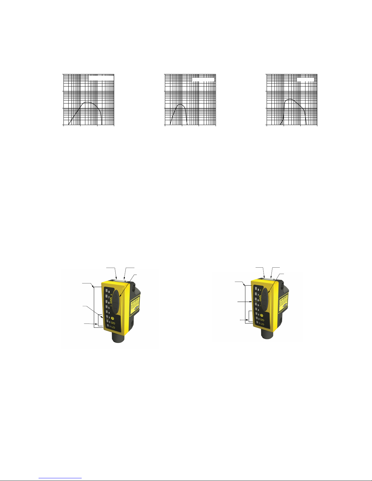
QS30LLP and QS30LLPC Series sensors are easy-to-use, high-performance laser sensors whose many configuration options make
them suitable for demanding applications. Each sensor features two identically configured outputs, one each NPN and PNP.
The compact housing has a large, easy-to-see bargraph display plus bright LEDs for easy configuration and status monitoring during
operation. The sensor can be side-mounted, using integral mounting holes, or front-mounted, via the 30 mm threaded barrel.
MODEL QS30LLP(Q) is configured using the Maximum Excess Gain SET procedure. It is useful for long-range applications and high
variations in contrast, such as beam-break applications where the target objects are larger than the beam. See Maximum Excess Gain
SET - Model QS30LLP on page 3 for more information.
MODEL QS30LLPC(Q) is configured using the Low-Contrast SET procedure. It is useful for small object detection and other applications
with small variations in contrast, such as yarn- or thread-break applications. See Low-Contrast SET - Model QS30LLPC on page 5 for
more information.
Figure 1. Model QS30LLP Features
Sensor Configuration
Sensor configuration is accomplished using the SET and SETUP modes. After SET mode has defined the sensing parameters, SETUP
mode may be used to add an OFF-delay or change the light/dark operate status. Manual Adjust may be used to fine-tune the thresholds.
Two push buttons, “+” and “-”, may be used to access and set sensing parameters. In addition, the remote wire also may be used for
some procedures (see below).
2 www.bannerengineering.com - tel: 763-544-3164 P/N 112355 Rev. C
Figure 2. Model QS30LLPC Features
Page 3
T T
T T T
T T
Darkest
(no signal)
Most Light
(saturated
signal)
Output OFFOutput ON
Location of switchpoint
adjusted via Manual Adjust
Factory-set
Threshold
T
WORLD-BEAM QS30 LLP and LLPC
Remote Configuration
The Remote Configuration function may be used to set the sensor threshold remotely or to disable the push buttons for security. Connect
the gray wire of the sensor to ground (0V dc), with a remote programming switch connected between them. Pulse the remote line according to the diagrams in the programming procedures. The length of the individual programming pulses is equal to the value T:
0.04 seconds ≤ T ≤ 0.8 seconds
Push Button Disable
In addition to its programming function, Remote Programming may be used to disable the push buttons for security. Disabling the push
buttons prevents undesired tampering with the programming settings. Connect the gray wire of the sensor as described on above, and
four-pulse to either enable or disable the push buttons:
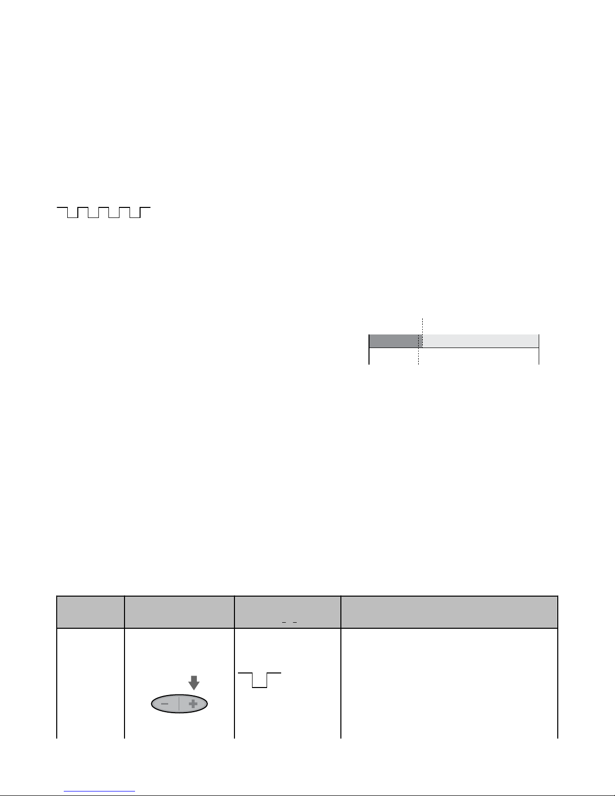
Maximum Excess Gain SET - Model QS30LLP
• Sets the sensor for maximum excess gain without allowing false proxing.
Provides maximum contrast between any reflector and a blocked condition
and is stable even in dirty environments.
• Useful for long-range applications and high variations in contrast, such as
beam-break applications where the target objects are larger than the
beam.
Sensor can be aimed at an object or the reflector during SET process to obtain
the same result. All conditions darker than the switchpoint condition result in
ON output (Dark Operate). Output ON and OFF conditions can be reversed by
changing Light/Dark Operate in SETUP mode (factory setting: Dark Operate).
Figure 3. Maximum Excess Gain SET (Dark Oper-
ate shown)
Manual Adjust – Maximum Excess Gain SET
During RUN mode, adjusts switchpoint up or down via “+” or “–” push buttons.
• Each push button “click” adjusts the switchpoint up by approximately 0.5X excess gain or down by the same increments.
• The lighted bargraph LEDs move to reflect the increase or decrease of excess gain relative to the switchpoint.
• LEDs #7 and 8 flash when maximum gain is achieved; LEDs #1 and 2 flash when minimum gain is achieved.
When the received signal is at any level greater than 6X excess gain, the first “–” (minus) click to reduce excess gain reduces it to the 6X
level. Subsequent “–” clicks result in decreased values as shown in Specifications on page 8 (approximately 2 clicks per LED change).
To return to maximum excess gain, either press “+” repeatedly until LEDs #7 and 8 flash, or hold the “+” button for longer than 2 seconds.
For example, in an application that results in 20X excess gain, pressing “–” once lowers the gain to 6X, exhibited by LED #8 ON. Pressing it twice more results in approximately 5X excess gain, exhibited by LED #7 ON. Holding the “+” button for 2 seconds results in a
return to maximum gain (20X), exhibited by LEDs #7 and 8 flashing.
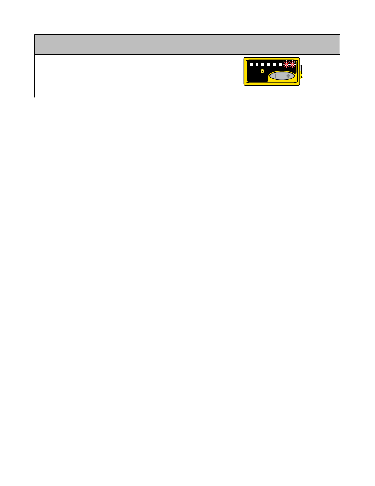
Push Button Remote
Set
Switchpoint
• Press and hold "+" > 2
seconds
P/N 112355 Rev. C www.bannerengineering.com - tel: 763-544-3164 3
(0.04 seconds < T < 0.8 seconds)
• Single-pulse remote
line.
Indicators
Green Power LED: OFF
Yellow Output LED: ON
Bargraph: #7 & 8 flashing
• Sensor returns to RUN mode with new settings
• Use Manual Adjust to increase or decrease sensor
excess gain
Page 4
11
3344556677
88
22
LOLO
DODO
+
GAIN
—
WORLD-BEAM QS30 LLP and LLPC
Push Button Remote
(0.04 seconds < T < 0.8 seconds)
Indicators
4 www.bannerengineering.com - tel: 763-544-3164 P/N 112355 Rev. C
Page 5
Darkest
(no signal)
Most Light
(saturated
signal)
Output ON Output OFF
Location of switchpoint
adjusted via Manual Adjust
Sensor
Switchpoint
Learned
Signal from
Retro Target
35% of
Learned Signal
(+) (-)
T
11
3344556677
88
22
LOLO
DODO
+
GAIN
—
11
3344556677
88
22
LOLO
DODO
+
—
GAIN
11
3344556677
88
22
LOLO
DODO
+
—
GAIN
WORLD-BEAM QS30 LLP and LLPC
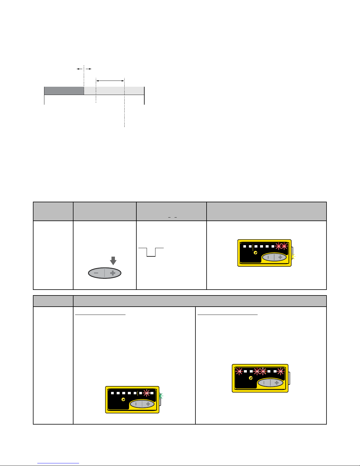
Low-Contrast SET - Model QS30LLPC
• Sets a switchpoint at 35 percent below the signal from the retroreflector.
• Useful for small object detection and other applications with small variations in contrast, such as yarn- or thread-break applications.
• Sensor must be aimed at the reflector during the SET process. All conditions darker than the switchpoint condition result in ON output (Dark Operate). Output ON and OFF conditions can be reversed by changing Light/
Dark Operate in SETUP mode (factory setting: Dark Operate).
Manual Adjust – Low-Contrast SET
During RUN mode, adjusts switchpoint up or down via “+” or “–” push buttons.
• Each push button “click” adjusts the switchpoint up by 5 percent of the
signal from the reflector or down by the same increments.
• The lighted bargraph LEDs move to reflect the increase or decrease in ex-
Figure 4. Low-Contrast SET (Dark Operate shown)
cess gain.
• LEDs #7 and 8 flash when maximum gain is achieved; LEDs #1 and 2
flash when minimum gain is achieved.
If the target object does not cause the output to change state, press the “–”
button to decrease the gain, making the sensor more sensitive to small signal
changes.
Set
Switchpoint
Sensor
Feedback
Push Button Remote
(0.04 seconds < T < 0.8 seconds)
• Align sensor to reflector
• Press and hold "+" > 2
• Align sensor to reflector
• Single-pulse remote line.
seconds
Switchpoint Accepted
Bargraph: #7 and 8 flash for 2 sec
Yellow Power LED: OFF
Green Power LED: ON
Bargraph: Appropriate LED ON
• Sensor returns to RUN mode with new settings.
• Use Manual Adjust to increase or decrease sensor
sensitivity.
Indicators
Green Power LED: OFF Yellow Output LED: ON
Indicators
Switchpoint Unacceptable
Bargraph: #1, 4, 5, and 8 flash for 2 sec
Green Power LED: ON
• Sensor returns to RUN mode without saving (maintains
previous settings)
P/N 112355 Rev. C www.bannerengineering.com - tel: 763-544-3164 5
Page 6
11
33
44
5
6
7
8
22
LO
DO
+
GAIN
—
SETUP
status
indicators
+
—
GAIN
+
—
+
—
+
—
+
—
+
—
GAINGAIN
WORLD-BEAM QS30 LLP and LLPC
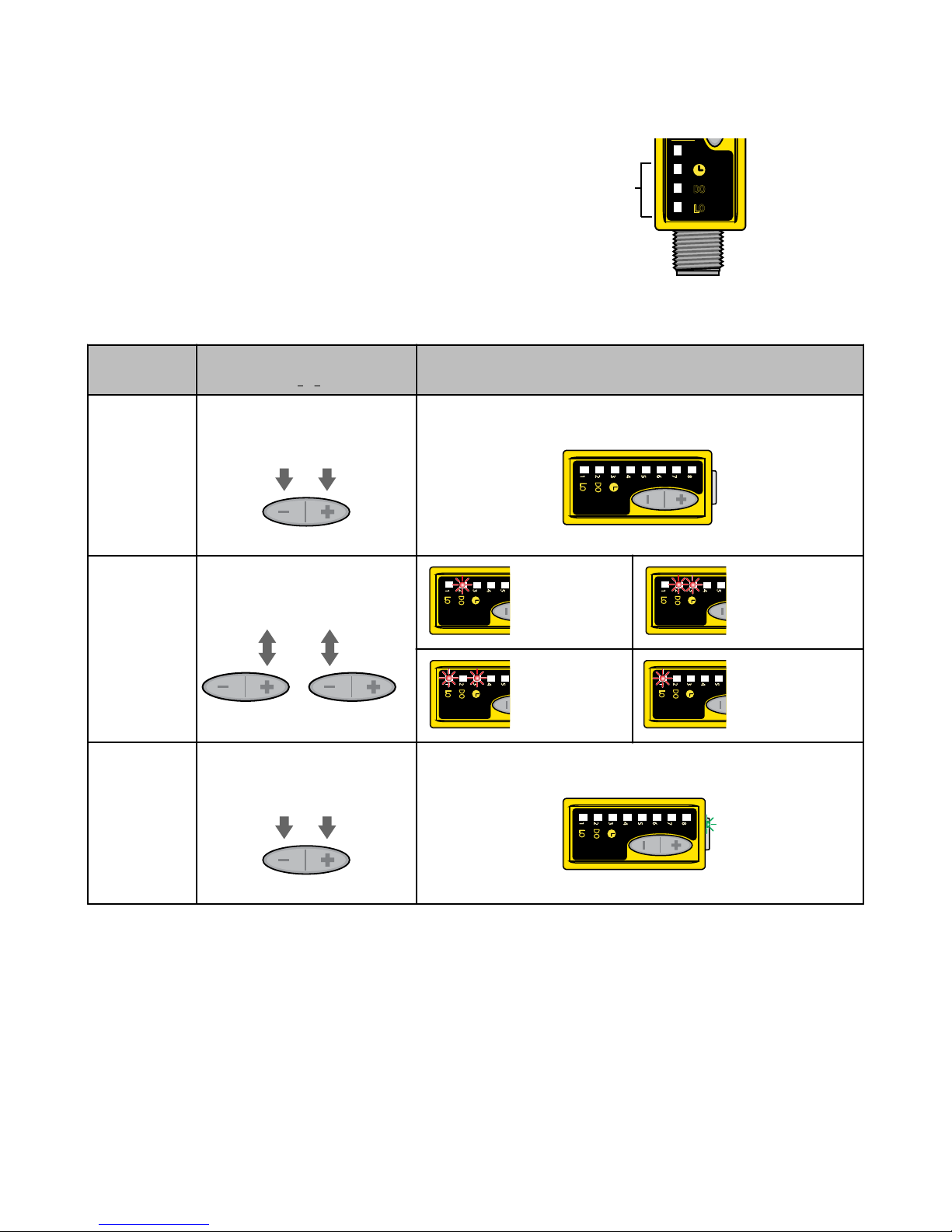
SETUP Mode
SETUP mode is accomplished via the sensor’s two push buttons.
It is used to change sensor output response for:
• Light or Dark Operate
• 30-millisecond pulse stretcher (OFF-delay), if required.
The status LEDs, active only during SETUP mode, indicate the
output response configuration when the sensor will be in RUN
mode.
Figure 5. SETUP Mode
Access SETUP
Mode
Select SETUP
Options
Return to RUN
Mode
Push Button
0.04 seconds
< T < 0.8 seconds
• Press and hold both push buttons > 2 seconds
• Click either push button to toggle
through the four possible setting
combinations.
or
• Press and hold both push buttons > 2 seconds
• Green Power LED turns OFF
DO, No Delay
LO, 30 ms Delay
• Green Power LED turns ON
Result
DO 30 ms Delay
LO, No Delay
6 www.bannerengineering.com - tel: 763-544-3164 P/N 112355 Rev. C
Page 7
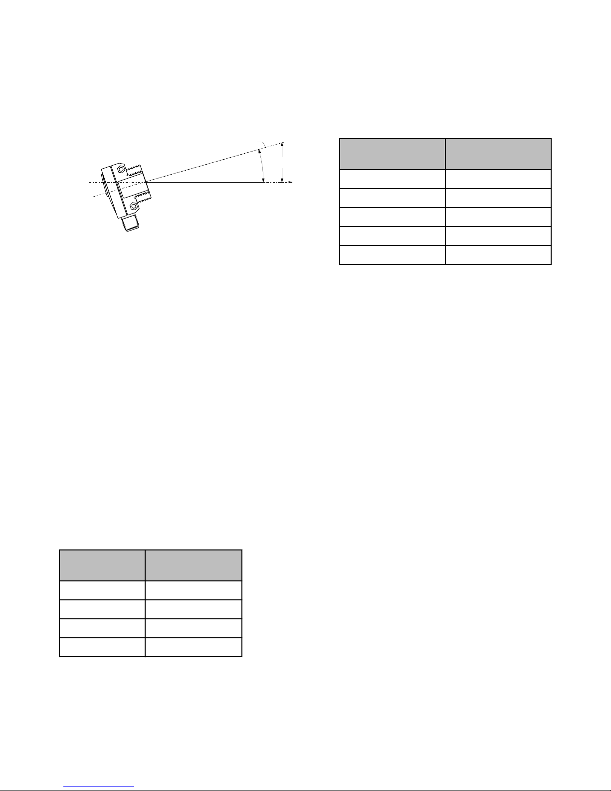
Sensing Distance = X
Ø = Misalignment Angle
Y = X(tan Ø)
Y
WORLD-BEAM QS30 LLP and LLPC
Installation Notes
Conventional retroreflective photoelectric sensors are extremely easy to align. Beam angles are wide, and retro targets are forgiving to
the light beam’s angle of incidence. The beam of this laser sensor is very narrow, compared with the beam of most retro sensors. As
Figure 6 indicates, the effect of angular misalignment can be dramatic. Alignment is critical because the beam may miss the retroreflective target unless the target is large.
Sensor-to-Target Distance (X)
Beam Displacement (Y)
for 1º of Misalignment
1.5 m (5 ft) 25 mm (1 in)
3 m (10 ft) 50 mm (2 in)
6 m (20 ft) 100 mm (4 in)
15 m (50 ft) 250 mm (10 in)
Figure 6. Beam Displacement per degree of misalignment
30 m (100 ft) 500 mm (20 in)
For example, with one BRT-51X51BM mounted at a distance of 6 m (20 ft) from the sensor, one degree of angular misalignment will
cause the center of the laser beam to miss the center of the target by 100 mm (4 in).
Alignment Tip
When using a small retroreflective target at medium or long range, it is often useful to temporarily attach (or suspend) a strip of retroreflective tape (e.g., BRT-TVHG-2X2) along a line that intersects the actual target. The visible red laser beam is easily seen in normal room
lighting on such tape. Sight along the beam toward the target (from behind the sensor). Move the sensor to scan the laser beam back
and forth across the retro tape strip. Use the tape strip to guide the beam onto the target.
Consider using sensor mounting bracket model SMB30SC (see Accessory Brackets on page 11). This swivel bracket can simplify multiple-axis alignment. Alignment is complete when the visible image is centered on the retro target. The perpendicularity of the laser beam
to the face of the retro target is forgiving, just as it is with a conventional retroreflective sensor.
Effective Beam Size
Unlike conventional retroreflective sensors, the retroreflective laser has the ability to sense relatively small profiles. Figure 7 indicates the
diameter of the smallest opaque rod which will reliably break the laser beam at several sensor-to-object distances using sensor model
QS30LLP(Q). These minimum object sizes were measured with the sensor aligned to a BRT-51X51BM reflector and the gain set to
maximum using the Max Excess Gain SET. This sensor is typically recommended for long-range applications of relatively small targets
that will completely break the beam.
Figure 7. Minimum object detection size vs.
distance from sensor, model QS30LLP(Q)
Smaller objects can be detected by using model QS30LLPC(Q), adjusting the
sensor gain down using the Manual Adjust, or performing a Low-Contrast SET
of the reflector. Objects as small as 2.0 mm can be reliably detected after per-
Sensor-to-Object
Distance (X)
Minimum Object Detection Size
forming the Low-Contrast SET at ranges up to 6 m (18 ft). This sensor is typically recommended for shorter-range applications detecting very small targets
that may break only a portion of the beam.
0.3 m (1 ft) 2.5 mm (0.10 in)
1.5 m (5 ft) 5.0 mm (0.20 in)
Note that the shape of the beam is elliptical. The minimum object sizes listed
assume passage of the rod across the major diameter of the ellipse (worst
case). It may be possible to detect objects smaller than the sizes listed if the
3 m (10 ft) 7.0 mm (0.28 in)
direction in which the objects pass through the beam can be controlled.
18 m (59 ft) 13 mm (0.52 in)
Retroreflector Recommendations
• BRT-51X51BM recommended for beam-block applications up to 18 m range.
• BRT-TVHG-2X2 recommended for applications up to 2 m range. (This retroreflector is an adhesive-backed sealed tape with micro-
P/N 112355 Rev. C www.bannerengineering.com - tel: 763-544-3164 7
prism geometry.)
Page 8
WORLD-BEAM QS30 LLP and LLPC
Specifications
Supply Voltage and Current
10 to 30V dc (10% max. ripple at 10% duty cycle) at 35
mA max current, exclusive of load
Sensing Beam
Visible red LED, 650 nm
Laser Classification
Class 1
Beam Size at Aperture
Approx. 3 mm
Supply Protection Circuitry
Protected against reverse polarity, over voltage, and
transient voltages
Delay at Power-Up
1 second max.; outputs do not conduct during this time
Output Configuration
Solid-state bipolar (SPDT): 1 current sourcing (PNP)
and 1 current sinking (NPN)
Rating: 150 mA maximum load
Off-state leakage current: < 10 µA at 30V dc
ON-state saturation voltage:
• NPN: less than 1.0V at 150 mA load
• PNP: less than 2.0V at 150 mA load
Output Protection Circuitry
Protected against output short-circuit, continuous overload, transient over-voltages, and false pulse on power-up
Output Response
500 microseconds
Repeatability
70 microseconds
Adjustments
2 push buttons and remote wire
• Easy push-button configuration
• Manually adjust (+/-) thresholds (push buttons only)
• LO/DO and OFF-delay configuration options
• Push-button lockout (from remote wire only)
Factory Defaults:
• No Delay
• Dark Operate
• Push buttons enabled
Indicators
Output conducting
8-Segment Red Bargraph
SETUP mode:
• Flashes Red when delay is selected
• Flashes Red when Dark Operate is selected
• Flashes Red when Light Operate is selected
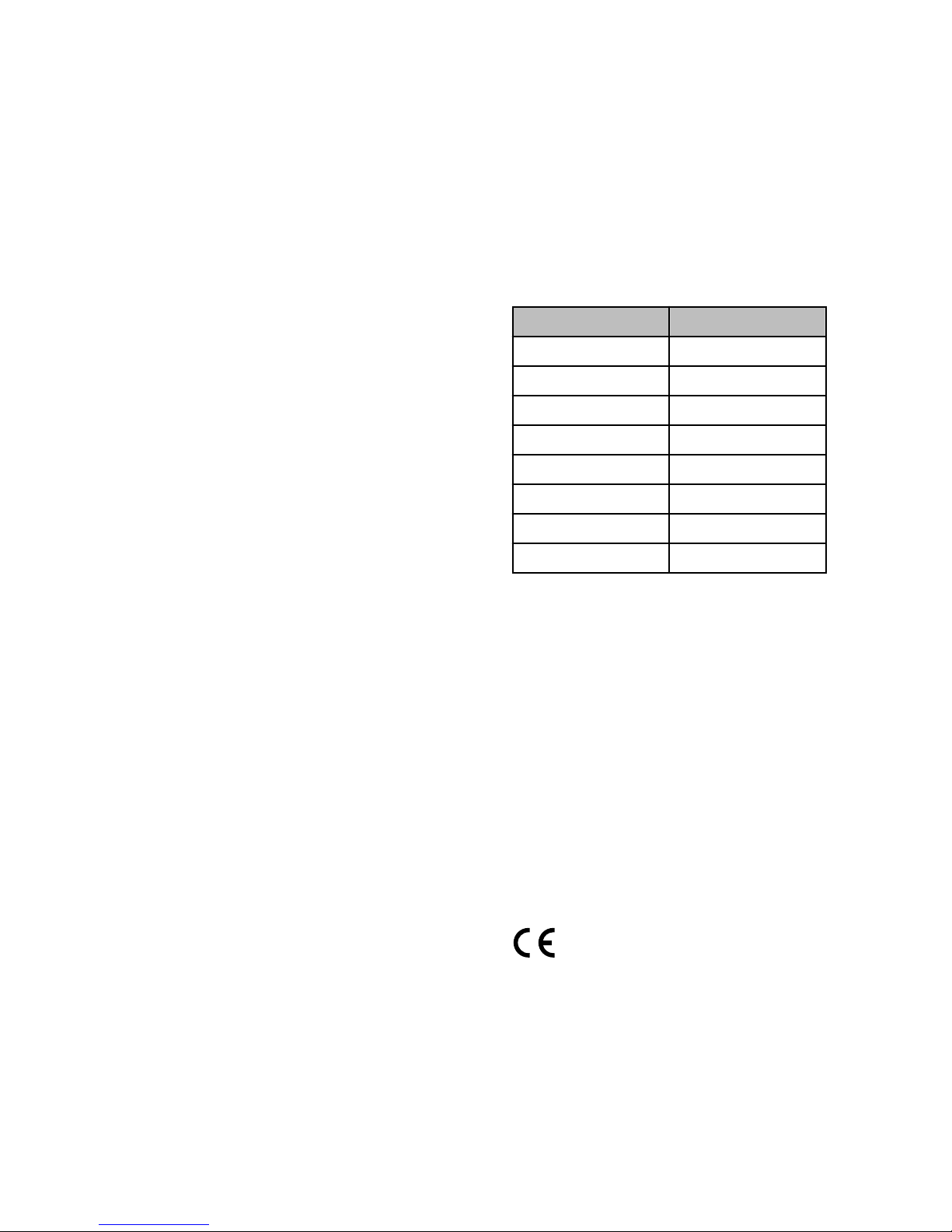
RUN mode:
Model QS30LLP Model QS30LLPC
LED 8: >6X LED 8: >2X
LED 7: 5-6X LED 7: 1.5-2X
LED 6: 4-5X LED 6: 1-1.5X
LED 5: 3-4X LED 5: 0.8X
LED 4: 2-3X LED 4: 0.6X
LED 3: 1-2X LED 3: 0.4X
LED 2: 0.5-1X LED 2: 0.2X
LED 1: 0-0.5X LED 1: 0X
Sensor calibration failure:
Construction
Environmental Rating
IEC IP67; NEMA 6
Connections
5-conductor 2 m (6.5 ft) PVC cable, 9 m (30 ft) PVC cable, or 5-pin integral Euro-style quick-disconnect fitting
Operating Conditions
Temp: –10° to +50° C (+14° to 122° F)
Relative Humidity: 90% at 50° C (non-condensing)
Vibration and Mechanical Shock
All models meet Mil. Std. 202F requirements. Method
201A (Vibration: 10 to 60Hz max. double amplitude
0.06 in, maximum acceleration 10G). Also meets IEC
947-5-2 requirements: 30G, 11 ms duration, half sine
wave.
Certifications
8 www.bannerengineering.com - tel: 763-544-3164 P/N 112355 Rev. C
Page 9
33.0 mm
(1.30")
12.5 mm
(0.49")
3.5 mm
(0.14")
44.0 mm
(1.73")
1.3 mm
(0.05")
22.0 mm
(0.87")
13.0 mm
(0.51")
5.0 mm
(0.20")
32.5 mm
(1.28")
35.0 mm
(1.38")
2 x ø3.3 mm (0.125")
max. torque
0.7 Nm (6 in lbs)
M30 x 1.5 Thread
max. torque
6 Nm (53 in lbs)
with included 30 mm
mounting nut
11
33
44
55
66
77
88
22
LO
DO
+
––
GAIN
WORLD-BEAM QS30 LLP and LLPC
Description of Laser Classes
Class 1 Lasers
Lasers that are safe under reasonably foreseeable conditions of operation, including the use of optical instruments for intrabeam viewing.
Reference IEC 60825-1:2001, Section 8.2.
CAUTION: Do Not Disassemble for Repair
Use of controls or adjustments or performance of proce-
dures other than those specified herein may result in
hazardous radiation exposure. Do NOT attempt to dis-
assemble this sensor for repair. A defective unit must
be returned to the manufacturer.
For Safe Laser Use (Class 1 or Class 2):
• Do not permit a person to stare at the laser.
• Do not point the laser at a person’s eye at close range.
• Mount open laser beam paths either above or below eye level, where practical.
• Terminate the beam emitted by the laser product at the end of its useful path.
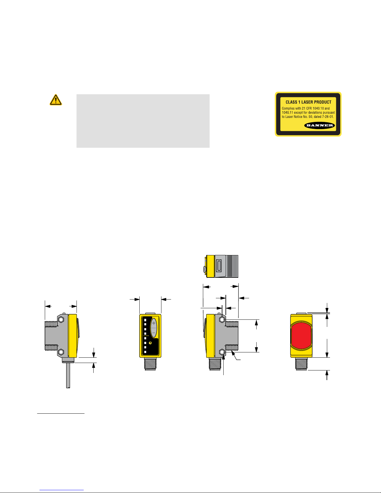
Dimensions
Cabled Models QD Models
Hardware Included: (2) M3 x 0.5 x 28 stainless steel machine screws, nuts, and washers
P/N 112355 Rev. C www.bannerengineering.com - tel: 763-544-3164 9
Page 10
bn
Remote
Teach
bu
wh
bk
gy
+
10 - 30V dc
–
Load
Load
150 mA max. load
bn
Remote
Teach
Note: Pink wire not used
bu
wh
bk
gy
+
10 - 30V dc
–
Load
Load
150 mA max. load
44 Typ.
ø 14.5
M12 x 1
2
3
4
1
5
32 Typ.
[1.26"]
30 Typ.
[1.18"]
ø 14.5 [0.57"]
M12 x 1
44 Typ.
ø 14.5
M12 x 1
2
3
4
1
5
WORLD-BEAM QS30 LLP and LLPC
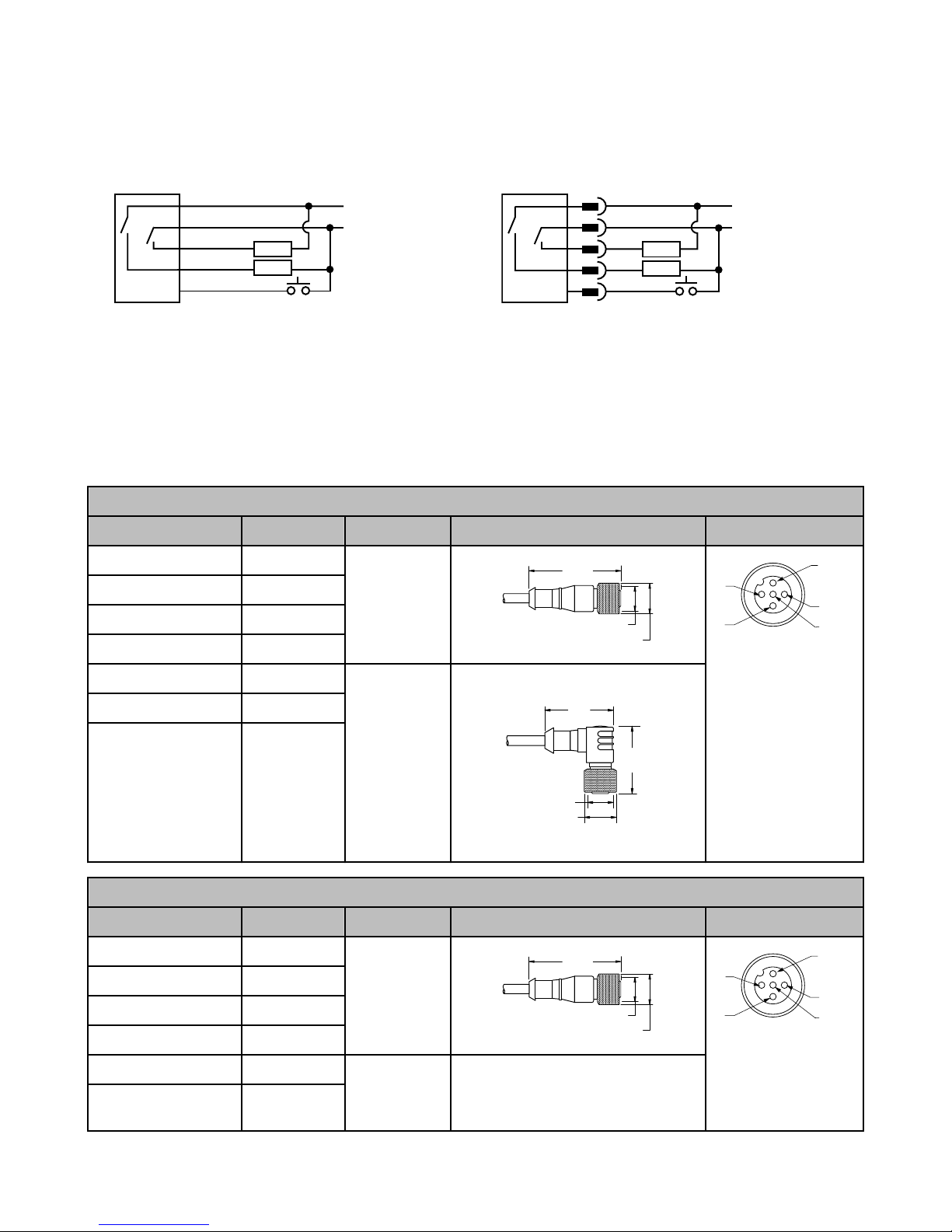
Hookups
Cabled Models QD Models
Accessories
Quick-Disconnect Cables
5-Pin Threaded M12/Euro-Style Cordsets
Model Length Style Dimensions Pinout
MQDC1-501.5 0.50 m (1.5 ft)
MQDC1-506 1.83 m (6 ft)
MQDC1-515 4.57 m (15 ft)
Straight
MQDC1-530 9.14 m (30 ft)
MQDC1-506RA 1.83 m (6 ft)
MQDC1-515RA 4.57 m (15 ft)
MQDC1-530RA 9.14 m (30 ft)
5-Pin Threaded M12/Euro-Style Cordsets
Model Length Style Dimensions Pinout
MQDC1-501.5 0.50 m (1.5 ft)
MQDC1-506 1.83 m (6 ft)
MQDC1-515 4.57 m (15 ft)
MQDC1-530 9.14 m (30 ft)
MQDC1-506RA 1.83 m (6 ft)
MQDC1-515RA 4.57 m (15 ft)
10 www.bannerengineering.com - tel: 763-544-3164 P/N 112355 Rev. C
Right-Angle
Straight
Right-Angle
1 = Brown
2 = White
3 = Blue
4 = Black
5 = Gray
1 = Brown
2 = White
3 = Blue
4 = Black
5 = Gray
Page 11
32 Typ.
[1.26"]
30 Typ.
[1.18"]
ø 14.5 [0.57"]
M12 x 1
67
58
29
B
A
WORLD-BEAM QS30 LLP and LLPC
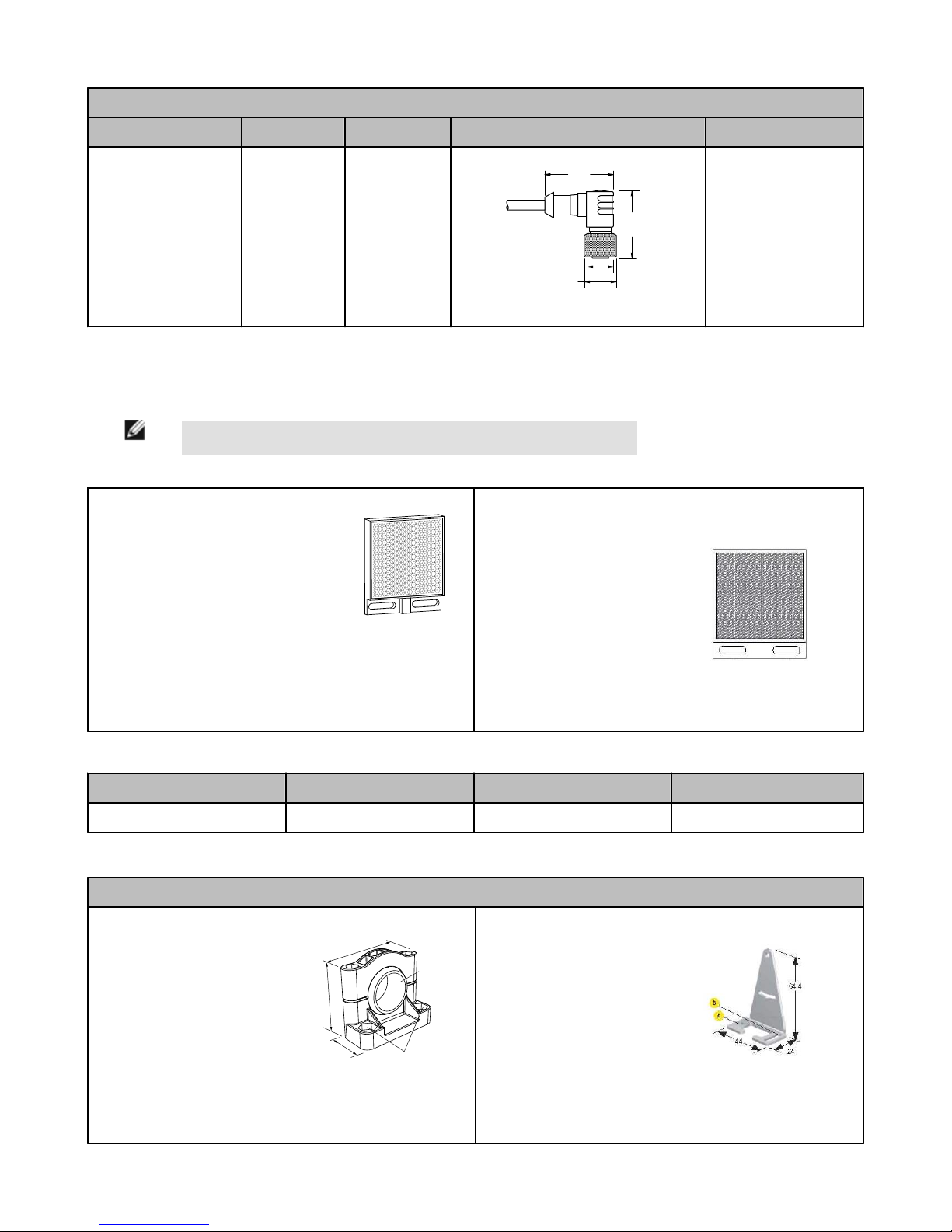
5-Pin Threaded M12/Euro-Style Cordsets
Model Length Style Dimensions Pinout
MQDC1-530RA
9.14 m (30 ft)
Retroreflective Targets
For additional information and a complete list of accessories, please refer to Banner Engineering website http://www.bannerengineer-
ing.com
NOTE: Polarized sensors require corner cube type retroreflective targets only.
BRT-2X2
• Square, acrylic target
• Reflectivity factor: 1.0
• Max. temperature: +50 °C (+122 ºF)
• Optional brackets are available
• Approximate size: 51 mm x 51 mm
BRT-51X51BM
• Square, acrylic target
• Reflectivity Factor: 1.5
• Max. Temperature: +50
°C (+122 °F)
• Micro-prism geometry
• Optional brackets are
available
• Approximate size: 51 mm
x 51 mm
Retroreflective Tape
Model Reflectivity Factor Maximum Temperature Size
BRT-TVHG-2X2 0.8 +60ºC (+140ºF) 50 x 50 mm
Accessory Brackets
Models
SMB30SC
• Swivel bracket with 30 mm
mounting hole for sensor
• Black reinforced thermoplastic polyester
• Stainless steel mounting
and swivel locking hardware included
Hole center spacing: A=ø 50.8
P/N 112355 Rev. C www.bannerengineering.com - tel: 763-544-3164 11
SMBQS30L
• Right-angle bracket for cable sensor models
• Clearance for M4 (#8)
hardware
• ± 12° tilt adjustment
• 14-ga. stainless steel
Hole center spacing: A to B=35.0
Page 12
WORLD-BEAM QS30 LLP and LLPC
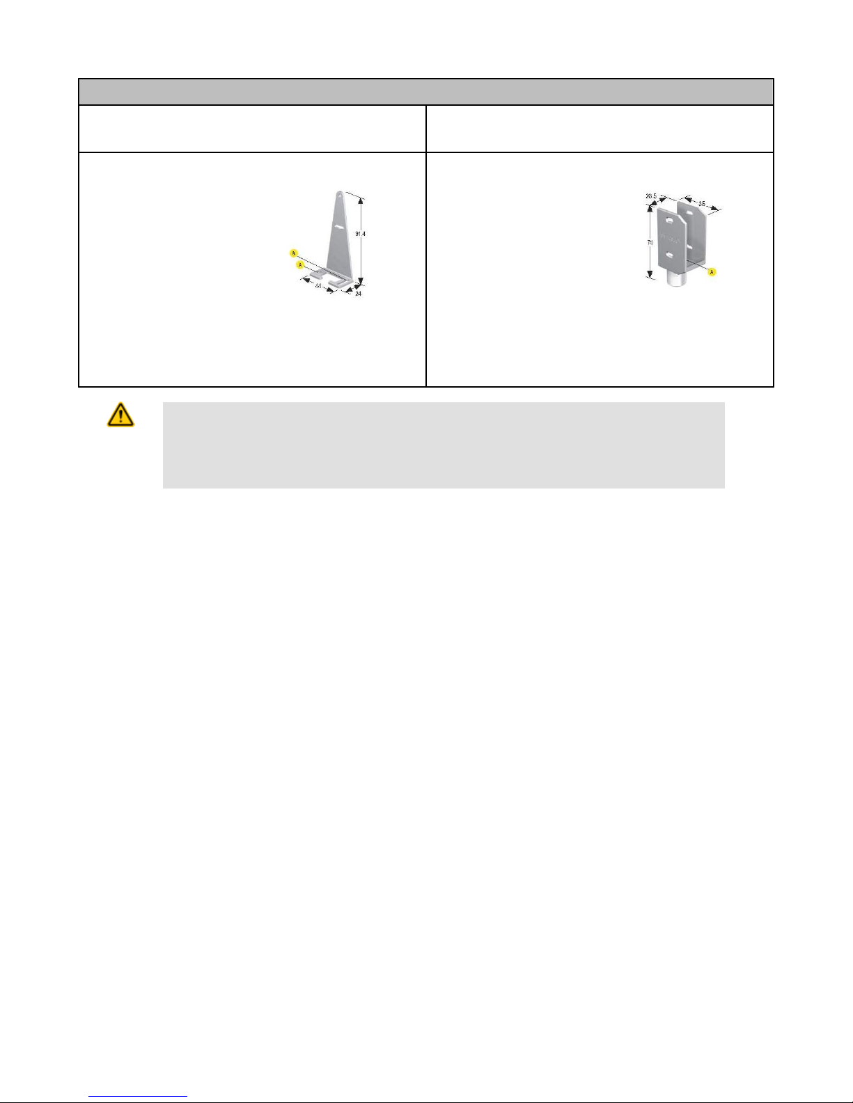
Models
Hole size: A=ø 7.0, B=ø 30.0 Hole size: A=ø 4.3, B=ø 4.25x16.3
SMBQS30LT
• Tall right-angle bracket for
QD models
• ± 8° tilt adjustment
• 14-ga. stainless steel
SMBQS30Y
• Heavy-duty die-cast bracket
• M18 vertical mount option
• ± 8° tilt adjustment with cabled units
• Includes nuts and lock
Hole center spacing: A to B=35.0
washer
Hole size: A=ø 15.3
Hole size: A=ø 4.3, B=ø 4.25x16.3
CAUTION: Do Not Disassemble for Repair
Use of controls or adjustments or performance of procedures other than those specified herein may result in
hazardous radiation exposure. Do NOT attempt to disassemble this sensor for repair. A defective unit must
be returned to the manufacturer.
Banner Engineering Corp Limited Warranty
Banner Engineering Corp. warrants its products to be free from defects in material and workmanship for one year following the date of
shipment. Banner Engineering Corp. will repair or replace, free of charge, any product of its manufacture which, at the time it is returned
to the factory, is found to have been defective during the warranty period. This warranty does not cover damage or liability for misuse,
abuse, or the improper application or installation of the Banner product.
THIS LIMITED WARRANTY IS EXCLUSIVE AND IN LIEU OF ALL OTHER WARRANTIES WHETHER EXPRESS OR IMPLIED (INCLUDING, WITHOUT LIMITATION, ANY WARRANTY OF MERCHANTABILITY OR FITNESS FOR A PARTICULAR PURPOSE), AND
WHETHER ARISING UNDER COURSE OF PERFORMANCE, COURSE OF DEALING OR TRADE USAGE.
This Warranty is exclusive and limited to repair or, at the discretion of Banner Engineering Corp., replacement. IN NO EVENT SHALL
BANNER ENGINEERING CORP. BE LIABLE TO BUYER OR ANY OTHER PERSON OR ENTITY FOR ANY EXTRA COSTS, EXPENSES, LOSSES, LOSS OF PROFITS, OR ANY INCIDENTAL, CONSEQUENTIAL OR SPECIAL DAMAGES RESULTING FROM ANY
PRODUCT DEFECT OR FROM THE USE OR INABILITY TO USE THE PRODUCT, WHETHER ARISING IN CONTRACT OR WARRANTY, STATUTE, TORT, STRICT LIABILITY, NEGLIGENCE, OR OTHERWISE.
Banner Engineering Corp. reserves the right to change, modify or improve the design of the product without assuming any obligations or
liabilities relating to any product previously manufactured by Banner Engineering Corp.
 Loading...