

Page 1
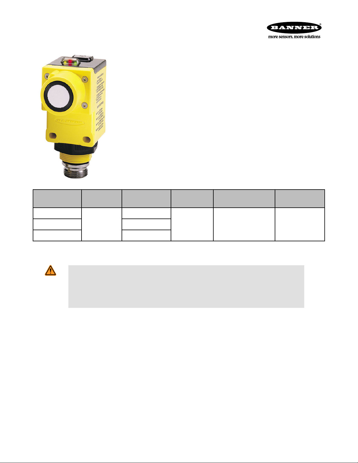
Q45U Ultrasonic Sensors with Analog Outputs (Long Range)
Piezoelectric proximity mode sensors with push-button programming of sensing window limits
• Ultrasonic proximity detection from 0.25 to 3.0 m (9.8 to 118 inches)
• Push-button TEACH-mode programming of sensing window limits
• Digital filtering for exceptional immunity to electrical and acoustic “noise”
• Selectable 0 to 10V dc voltage sourcing or 4 to 20 mA current sourcing analog outputs
• Selectable output slope: positive or negative with increasing target distance
• Wide operating temperature range of –25 to +70 °C; all models include temperature compensation
• Rugged design for use in demanding sensing environments; rated IEC IP67,
NEMA 6P
• Choose models with integral 2 m (6.5 ft) or 9 m (30 ft) cable, or with Mini-style or
Euro-style quick-disconnect fitting
• Input for remote TEACH-mode programming of window limits
Models
Q45ULIU64BCR
Q45ULIU64BCRQ 5-Pin Mini-style QD
Q45ULIU64BCRQ6 5-Pin Euro-style QD
Standard 2 m (6.5 ft) cable models are listed. To order the 9 m (30 ft) cable model, add suffix "W/30" to the cabled model number. For
example, Q45ULIU64BCR W/30. Models with a QD connector require a mating cable.
Temperature
Compensation
Yes
WARNING: Not To Be Used for Personnel Protection
Never use this device as a sensing device for personnel protection. Doing so could lead to serious
injury or death. This device does not include the self-checking redundant circuitry necessary to allow its
use in personnel safety applications. A sensor failure or malfunction can cause either an energized or deenergized sensor output condition.
Cable Supply Voltage Output Type Response Time
2 m (6.5 ft)
15–24V dc
Selectable 0–10V dc or 4–
20 mA sourcing
Adjustable from 80
milliseconds to 2.56
seconds
Temperature Compensation
All models listed above feature temperature compensation. An increase in air temperature shifts both sensing window limits closer to the
sensor. Conversely, a decrease in air temperature shifts both limits further away from the sensor. The shift is approximately 3.5% of the
limit distance for a 20 °C change in temperature.
Temperature compensated models maintain the position of both sensing window limits to within 1% of each limit distance over the 0 to
+50 °C range, and to within 2.5% over the full operating range of from –25 to +70 °C.
Setting the Near and Far Sensing Limits
The Q45U features a single push button for programming of sensing window near and far limits. For more information, refer to Program-
ming the Window Limits on page 4.
Status Indicators
Status indicator LEDs are visible through the transparent, o-ring sealed acrylic top cover. Indicator function in the Run mode is, as follows:
P/N 48456 Rev. E 8/21/2013
Page 2

Limits
N
1 2 3 4 5
3
4
5
1
2
7
Resp.
Speed
+
–
6
1ON2 3 4
Q45U Ultrasonic Sensors with Analog Outputs (Long Range)
• The green LED is solid when power is applied to the sensor and flashes to indicate a current output fault.
• The red LED is solid when an echo is received and flashes at a rate proportional to echo strength.
• The amber LED is solid when the target is within the operating window limits.
The 5-segment moving dot LED indicator displays the relative position of the target within the programmed sensing window. LED #1
flashes when the target is closer than the near limit. LED #5 flashes when the target is beyond the far limit.
1 - Push button for programming sensing window limits
2 - 5-segment target position indicator (N = near)
3 - Green POWER indicator LED
4 - Red SIGNAL indicator LED
5 - Amber OUTPUT indicator LED
6 - Response adjustment
7 - Slots for removing inner cover
Figure 1. Analog Q45U Features
Output Response Settings
Important: Remove power before making any internal adjustments.
Using the two slots shown in Figure 1. Analog Q45U Features on page 2, a small flat-blade screwdriver may be used to lift up and
remove the black inner cover to expose the 4-position DIP switch. Use these DIP switches to program the output slope, output mode,
loss of echo, and min./max. output value default.
DIP Switch Function Settings
1 Output slope On = Output value increases with distance
Off* = Output value decreases with distance
2 Output mode On = Current output enabled
Off* = Voltage output enabled
3 Loss of echo On = Min - Max Mode
4 Min-Max On* = Default to maximum output value
Off* = Hold Mode
Off = Default to minimum output value
* Factory default setting.
2 www.bannerengineering.com - tel: 763-544-3164 P/N 48456 Rev. E
Figure 2. DIP Switches for Q45U Sensors
Page 3
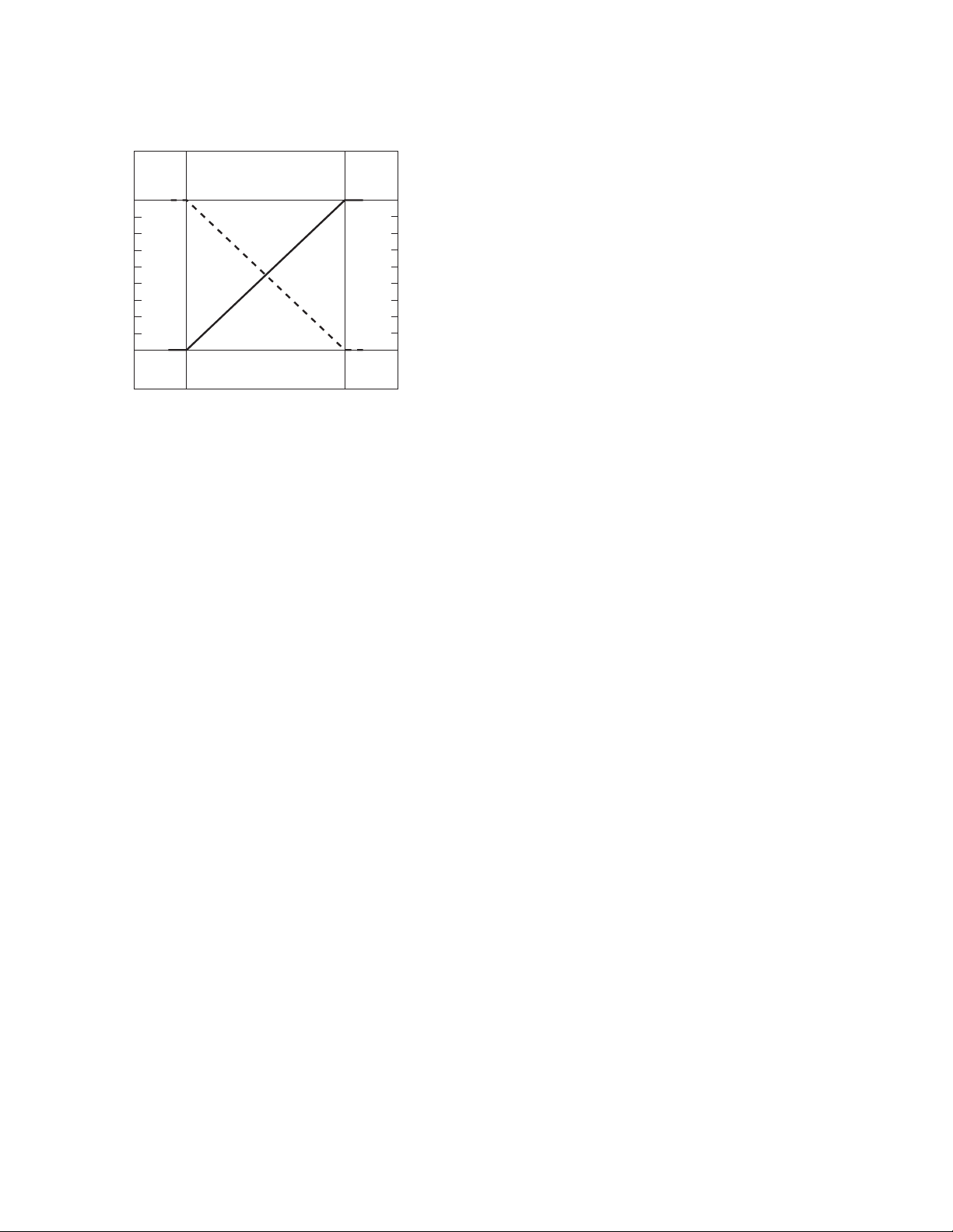
0
Near
Window
Far
Window
10
Target Position
Analog Output (V dc)
Positive
Slope
Voltage/Current-Sourcing Models
4
20
Analog Output (mA)
Q45U Ultrasonic Sensors with Analog Outputs (Long Range)
DIP Switch 1: Output Slope Select
Figure 3. Output as a function of target position
On = Direct = Output value (voltage or current) increases with increasing distance of the target from the sensor
Off* = Inverse = Output value decreases with increasing distance
of the target from the sensor
DIP Switch 2: Output Mode Select
On = The 4 to 20 mA current output (white wire) is enabled
Off* = The 0 to 10V dc voltage output (black wire) is enabled
This switch configures the D/A driver to use either the current output or the voltage output driver. This output function can only be set with
the power to the sensor turned off.
DIP Switch 3: Loss of Echo Mode Select
On = Min - Max Mode
Off* = Hold Mode
This switch determines the output response to the loss of echo. The “Hold Mode” (Switch 3 Off*) maintains the output at the value
present at the time of echo loss. The “Min - Max Mode” (Switch 3 On) drives the output to either the minimum value (0V or 4 mA or the
maximum value (10V or 20 mA) when the echo is lost. Minimum or maximum value is selected by DIP switch 4.
DIP Switch 4: Min-Max Default
On* = Default to maximum output value at loss of echo
Off = Default to minimum output value at loss of echo
Switch 4 selects the output response to loss of echo when “Min - Max Mode” is selected by DIP switch 3.
Response Speed Adjustments
The speed of the output response is set using the single-turn potentiometer. There are six values for response speed, which relate directly to the number of sensing cycles over which the output value is averaged. The response value is set by aligning the slot of the potentiometer with one of the marked positions.
P/N 48456 Rev. E www.bannerengineering.com - tel: 763-544-3164 3
Page 4

1
2
3 4
5
6
+
–
Position Response Speed Potentiometer Positions
Q45U Ultrasonic Sensors with Analog Outputs (Long Range)
1 80 milliseconds (2 cycles)
2 160 milliseconds (4 cycles)
3 320 milliseconds (8 cycles)
4 640 milliseconds (16 cycles)
5 1.28 seconds (32 cycles)
6 2.56 seconds (64 cycles)
This example shows the potentiometer set at position number 4. There
Figure 4. Response adjustment positions
are no numbers on the actual product label.
Programming the Window Limits
Use the “Limits” push button, located under the transparent top cover, to program the near and the far limits. The near limit may be set as
close as 250 mm (9.8 inches) and the far limit may be set as far as 3.0 m (118 inches) from the transducer face. Minimum window width
is 25 mm (1 inch). Whenever possible, use the actual target to be sensed when setting the window limits. The following procedure begins
with the sensor in Run mode.
Step Description LED Indicator Status
1 Access Limit Programming Mode. Push and hold until the
green indicator LED turns off (approximately 2 seconds).
2 Set the First Limit (Near or Far). Place the target at the
first limit and press the push button for less than 2 seconds.
Green: Goes off
Amber: Solid on to indicate ready for teaching first limit
Red: Flashes to indicate strength of echo or is off if no target is
present
Green: Remains off
Amber: Flashes at 2 Hz to indicate ready for teaching second
limit
Red: Solid on for a moment, then resumes flashing to indicate
strength of echo
3 Set the Second Limit (Far or Near). Place the target at the
second limit and press the push button for less than 2 seconds
Notes Regarding Window Limit Programming
1. Either the near or far limit may be programmed, first.
2. There is a 2-minute time-out for programming of the first limit. The sensor will return to Run mode with the previously programmed
limits. There is no time-out between programming of the first and second limit.
3. The programming sequence may be cancelled at any time by pressing and holding the push button for ≥ 2 seconds. The sensor
returns to Run mode with the previously programmed limits.
4. During limit programming, the 5-segment moving dot indicator displays the relative target position between 0 and 4.0 m (the maximum recommended far limit position is 3.0 m (118 inches)).
5. If the target is positioned between 3.0 m (118 inches) and 4.0 m, the 5th segment of the moving dot indicator flashes to indicate
that a valid echo is received, but the target is beyond the recommended 3.0 m (118 inches) maximum far limit.
6. If a limit is rejected during either programming step, the sensor will revert to the first limit programming step (Step 2 in programming
chart). This will be indicated by Green - off, Red - flashing to indicate signal strength, and Amber - solid on.
7. If both limits are accepted, the sensor will return to Run mode, which is indicated by the solid on Green LED.
4 www.bannerengineering.com - tel: 763-544-3164 P/N 48456 Rev. E
Green: Remains off, then comes on solid (returns to Run mode)
Amber: Solid on for a moment, then is either on or off to indicate output state (returns to Run mode)
Red: Solid on for a moment, then resumes flashing to indicate
strength of echo (returns to Run mode)
Page 5

Q45U Ultrasonic Sensors with Analog Outputs (Long Range)
8. If the target is held at the same position for programming of both limits, the sensor will establish a 50 mm-wide sensing window,
centered on the target position.
Specifications
Proximity Mode Range
Near limit: 250 mm (9.8 inches) min
Far limit: 3.0 m (118 inches) max
The far limit may be extended as far as 3.9 m for good
acoustical targets (hard surfaces with area > 100 cm²)
Supply Voltage and Current
15 to 24V dc (10% maximum ripple) at 100 mA, exclusive of load
Supply Protection Circuitry
Protected against reverse polarity and transient voltages
Indicators
Three status LEDs:
Green solid = power to sensor is ON
Green flashing = current output fault detected (indi-
cates that the 4-20 mA current path to ground has
been opened)
Amber solid = target is sensed within the window limits
(Amber LED also indicates programming status during
setup mode)
Red flashing = indicates relative strength of received
echo
5-segment moving dot LED indicates the position of the
target within the sensing window
Construction
Molded PBT thermoplastic polyester housing, o-ring
sealed transparent acrylic top cover, and stainless
steel hardware. Q45U sensors are designed to withstand 1200 psi washdown. The base of cabled models
has a 1/2"-14NPS internal conduit thread
Connections
2 m (6.5 ft) or 9 m (30 ft) attached cable, or 5-pin Ministyle or 5-pin Euro-style quick-disconnect fitting
Output Configuration
One voltage sourcing and one current sourcing; one or
the other output is enabled by internal programming
switch #2. Output function may be programmed by a 4position DIP switch located on top of the sensor, beneath the transparent o-ring sealed acrylic cover.
Output Rating
Voltage sourcing: 0 to 10V dc, 10 mA maximum
Current sourcing: 4 to 20 mA, 1 to 500 ohm impedance
Output Protection Circuitry
Both outputs are protected against continuous overload
and short circuit
Performance Specifications
Sensing Repeatability: ±0.1% of the measured distance (±0.50 mm minimum)
Sensing Resolution: 0.50 mm (0.02 in)
Analog Output Resolutions: 2 mV, 3 μA
Environmental Rating
Leakproof design is rated IEC IP67; NEMA 6P
Operating Temperature
Temperature: –25 to +70 °C (–13 to +158 °F)
Maximum relative humidity: 100%
Vibration and Mechanical Shock
All models meet Mil. Std. 202F requirements. Method
201A (Vibration: 10 to 60Hz max., double amplitude
0.06-inch, maximum acceleration 10G). Method 213B
conditions H & I (Shock: 75G with unit operating; 100G
for nonoperation). Also meets IEC 947-5-2 requirements: 30G, 11 ms duration, half sine wave
Application Notes
Minimum target size: 50 mm x 50 mm aluminum plate
at 3.0 m (118")
Remote Programming the Window Limits
Connect the yellow wire of the Analog Q45U to a switch or process controller for remote programming of the sensing window limits. The
programming procedure is the same as for the push button. A remote programming input is generated when +5 to 24V dc is applied to
the yellow wire. The timing diagrams, below, define the required input pulses.
H = +5 to 24V dc
L = <2V dc (or open circuit)
P/N 48456 Rev. E www.bannerengineering.com - tel: 763-544-3164 5
Page 6

Step 1
Access Limit
Programming Mode
Step 2
Set First Limit
(Near or Far)
Step 3
Set Second Limit
(Far or Near)
T T >2 sec
Wait >0.8 seconds
before next input
H
L
T
0.04 sec <T< 0.8 sec
Wait >2 seconds before next input
H
L
T
0.04 sec <T< 0.8 sec
H
L
Lateral Distance
Sensing Distance
4 in
8 in
12 in
16 in
4 in
8 in
12 in
16 in
100 mm
200 mm
300 mm
100 mm
00
200 mm
300 mm
400 mm
400 mm
0 500 mm
20 in
1000 mm
40 in
1500 mm
60 in
2000 mm
80 in
2500 mm
100 in
3000 mm
120 in
3500 mm
140 in
4000 mm
160 in
Lateral Distance
Sensing Distance
4 in
8 in
12 in
16 in
4 in
8 in
12 in
16 in
100 mm
200 mm
300 mm
100 mm
00
200 mm
300 mm
400 mm
400 mm
0 500 mm
20 in
1000 mm
40 in
1500 mm
60 in
2000 mm
80 in
2500 mm
100 in
3000 mm
120 in
3500 mm
140 in
4000 mm
160 in
Q45U Ultrasonic Sensors with Analog Outputs (Long Range)
Notes regarding remote window limit programming:
1. The push button is disabled during remote limit programming. (The remote programming input is disabled during push button pro-
2. Also see the notes regarding window limit programming.
Performance Curves
6 www.bannerengineering.com - tel: 763-544-3164 P/N 48456 Rev. E
Figure 5. Remote programming the window limits
gramming.)
Effective Beam with Plate Target (Typical) Effective Beam with Rod Target (Typical)
Page 7

bn
wh
bu
–
bk
ye or gy
15–24V dc
4 to 20mA
0 to 10V
Remote teach
(+5–24V dc)
Load
Load
+
shield
bn
wh
bu
–
bk
ye
4 to 20mA
0 to 10V
Remote teach
(+5–24V dc)
Load
Load
+
15–24V dc
shield
bn
wh
bu
–
bk
gy
4 to 20mA
0 to 10V
Remote teach
(+5–24V dc)
Load
Load
+
15–24V dc
shield
4
3
1
5
2
2
3
4
1
5
79.4 mm
(3.13")
44.5 mm
(1.75")
69.0 mm
(2.72")
87.6 mm
(3.45")
30.0 mm
(1.18")
Internal Thread: (1/2 NPSM)
External Thread: (M30 x 1.5)
ø6.1 mm (.24")
2 m (6.5') Cable
7.1 mm
(0.28")
4.5 mm (#10) Screw
Clearance (2)
50.3 mm
(1.98")
6.4 mm (0.25")
Transducer
Centerline
Transparent Cover (Gasketed)
View: Sensing Status
Output Load Status
Power
Open to Access:
Push Button for
Programming of Sensing
Window Limits
Hex Nut Supplied
14 mm (0.6")
15 mm (0.6")
Q45U Ultrasonic Sensors with Analog Outputs (Long Range)
Hookup Diagrams for Q45U Sensors with Analog Outputs
Sensor with Attached Cable Sensor with 5-pin Mini-style QD Sensor with 5-pin Euro-style QD
Banner Engineering Corp recommends the
shield wire be connected to earth ground or
dc common.
1 = brown
2 = white
3 = blue
4 = black
5 = yellow
1 = brown
2 = white
3 = blue
4 = black
5 = gray
Dimensions
Cabled Models 5-pin Mini-style QD Models 5-pin Euro-style QD Models
P/N 48456 Rev. E www.bannerengineering.com - tel: 763-544-3164 7
Page 8

7/8-16UN-2B
ø 28 mm max.
(1.1")
61 mm max.
(2.4")
4
3
1
5
2
44 Typ.
ø 14.5
M12 x 1
2
3
4
1
5
32 Typ.
[1.26"]
30 Typ.
[1.18"]
ø 14.5 [0.57"]
M12 x 1
66
56
13
A
B
Q45U Ultrasonic Sensors with Analog Outputs (Long Range)
Accessories
5-Pin Mini-Style Cordsets with Shield
Model Length Style Dimensions Pinout (Female)
MBCC2-506 1.83 m (6 ft)
MBCC2-515 4.57 m (15 ft)
Straight
MBCC2-530 9.14 m (30 ft)
1 = Brown
2 = White
3 = Blue
4 = Black
5 = Yellow
5-Pin Threaded M12/Euro-Style Cordsets with Shield
Model Length Style Dimensions Pinout
MQDEC2-506 1.83 m (6 ft)
MQDEC2-515 4.57 m (15 ft)
Straight
MQDEC2-530 9.14 m (30 ft)
MQDEC2-550 15.2 m (50 ft)
MQDEC2-506RA 1.83 m (6 ft)
MQDEC2-515RA 4.57 m (15 ft)
MQDEC2-530RA 9.14 m (30 ft)
Right-Angle
1 = Brown
2 = White
3 = Blue
4 = Black
5 = Gray
MQDEC2-550RA 15.2 m (50 ft)
SMB30S
• Swivel bracket with 30 mm
mounting hole for sensor
• Adjustable captive swivel
ball
• Black reinforced thermo-
plastic polyester
• 30 mm split clamp, black
• Stainless steel mounting
• Mounting hole for 30 mm
SMB30C
PBT bracket
hardware included
sensor
• Stainless steel mounting
and swivel locking hard-
ware included
Hole center spacing: A=ø 45
Hole size: B=ø 27.2
Hole center spacing: A=ø ##.#
Hole size: A=ø #.#, B=ø ##.#
8 www.bannerengineering.com - tel: 763-544-3164 P/N 48456 Rev. E
Page 9

70
57
A
B
C
57
Q45U Ultrasonic Sensors with Analog Outputs (Long Range)
SMB30MM
• 12-ga. stainless steel
bracket with curved
mounting slots for versatile
orientation
• Clearance for M6 (¼ in)
hardware
• Mounting hole for 30 mm
sensor
Hole center spacing: A = 51, A to B = 25.4
Hole size: A = 42.6 x 7, B = ø 6.4, C = ø 30.1
Banner Engineering Corp Limited Warranty
Banner Engineering Corp. warrants its products to be free from defects in material and workmanship for one year following the date of
shipment. Banner Engineering Corp. will repair or replace, free of charge, any product of its manufacture which, at the time it is returned
to the factory, is found to have been defective during the warranty period. This warranty does not cover damage or liability for misuse,
abuse, or the improper application or installation of the Banner product.
THIS LIMITED WARRANTY IS EXCLUSIVE AND IN LIEU OF ALL OTHER WARRANTIES WHETHER EXPRESS OR IMPLIED (INCLUDING, WITHOUT LIMITATION, ANY WARRANTY OF MERCHANTABILITY OR FITNESS FOR A PARTICULAR PURPOSE), AND
WHETHER ARISING UNDER COURSE OF PERFORMANCE, COURSE OF DEALING OR TRADE USAGE.
This Warranty is exclusive and limited to repair or, at the discretion of Banner Engineering Corp., replacement. IN NO EVENT SHALL
BANNER ENGINEERING CORP. BE LIABLE TO BUYER OR ANY OTHER PERSON OR ENTITY FOR ANY EXTRA COSTS, EXPENSES, LOSSES, LOSS OF PROFITS, OR ANY INCIDENTAL, CONSEQUENTIAL OR SPECIAL DAMAGES RESULTING FROM ANY
PRODUCT DEFECT OR FROM THE USE OR INABILITY TO USE THE PRODUCT, WHETHER ARISING IN CONTRACT OR WARRANTY, STATUTE, TORT, STRICT LIABILITY, NEGLIGENCE, OR OTHERWISE.
Banner Engineering Corp. reserves the right to change, modify or improve the design of the product without assuming any obligations or
liabilities relating to any product previously manufactured by Banner Engineering Corp.
www.bannerengineering.com - tel: 763-544-3164
 Loading...