

Page 1
45DN Bus Expansion Cards
For use with Q45X Photoelectric Sensors on DeviceNet™ Bus Networks
Printed in USA 05/03 P/N 39667 rev. C
• Banner model 45DN plug-in bus cards enable a Banner Q45X Series sensor to
establish a logical relationship between the sensor’s output and other compatible
devices on a DeviceNet™ bus network.
• The following features of the 45DN are programmable via the network with a
configuration tool*:
Feature Range (default)
Network Address 0-63 (63)
Baud Rate 125K, 250K, 500K (125K)
Operate Mode** Light Operate or Dark Operate (Light Operate)
All 45DNs support the following connection type:
The Explicit Message Connection, which is required to Set and Get sensor
Attributes.
The 45DN1 supports the following connection type:
The Bit Strobe Connection, which responds to a master’s request.
The 45DN2 supports the following connection type:
The Change of State Connection, which responds to the slave’s change of state.
I/O Response (8-bit word of data):
Bit 0: 0 Output is OFF
1 Output is ON
Bit 1: 0 Alarm is OFF
1 Alarm is ON
Bits 2-7 Not used: always 0
* Configuration may be simplified through use of an Electronic Data Sheet (Banner
model EDS 40223)
** The Light/Dark Operate switch in the Q45 sensor must be set to the Light Operate
position (the factory setting).
Features
WARNING . . .
Not To Be Used for Personnel Protection
Never use these products as sensing devices for personnel protection. Doing so could lead to serious injury or death.
These sensors do NOT include the self-checking redundant circuitry necessary to allow their use in personnel safety applications. A
sensor failure or malfunction can cause either an energized or de-energized sensor output condition. Consult your current Banner Safety Products
catalog for safety products which meet OSHA, ANSI and IEC standards for personnel protection.
Model Part Number Used with Sensor Communications I/O Supported
45DN1 40059 All Q45XB6 models, except emitter DeviceNet Bit Strobe Connection
45DN2 49215 All Q45XB6 models, except emitter DeviceNet Change of State Connection
45DNE1 40907 Q45X6EQ emitter
Allows emitter to be powered from
DeviceNet bus; does not communicate
Models
!
Page 2
Q45XDN
™
2 P/N 39667 rev. C
Banner Engineering Corp. • Minneapolis, MN U.S.A.
www.bannerengineering.com • Tel: 763.544.3164
The 45DN is one of a family of bus expansion cards for Q45X Series sensors which
includes models for use on AS-Interface, SDS
™
, and DeviceNet.
Use of a 45DN bus expansion card turns the Q45X into a “smart” sensor which can
be connected to a DeviceNet bus network using a simple “dumb drop” junction box or
a “T” connector. Plugging a bus expansion card into a Q45X Series sensor
automatically converts the basic sensor outputs to a pair of datacom connections with
the proper protocol for use on a DeviceNet bus network. Q45X sensors without bus
cards (i. e. “dumb sensors”) may also be added to any bus system, via a “smart
drop” junction box. Basic Q45X sensors (without bus expansion cards) interface
directly to PLC dc inputs. The block diagram below illustrates how “smart” and
“dumb” Q45X Series sensors can be mixed together on the same bus network.
Overview
B
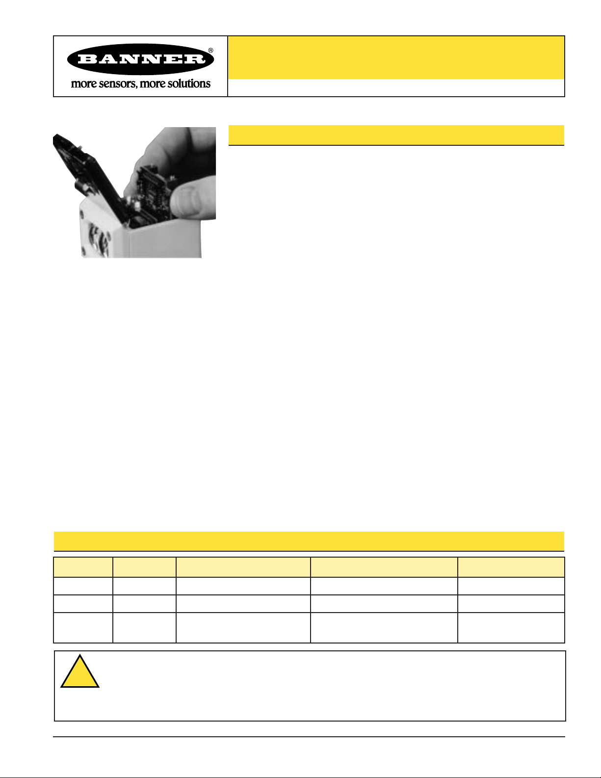
Installation and Removal
Modules are installed through the top of the sensor, as follows:
1) Remove power from the sensor.
2) Loosen the top cover hold-down screw and raise the cover. The cover is hinged at
the front.
3) Using a small screwdriver inserted into one of the slots at the rear of the inside
black cover, lift up and remove the black inside cover (Figure 2A).
4) Insert the card in the expansion slot so that the connector receptacles on the card
align with the connector pins inside the sensor. Slide the card down into the slot
until the connectors are fully engaged (Figure 2B).
5) Replace the original black inside cover with the one supplied with the 45DN card.
6) Make sure that the Light/Dark Operate switch in the Q45X sensor is set to the
Light Operate position.
Modules are removed through the top of the sensor, as follows:
1) Follow steps 1 through 3 of the installation procedure, above.
2) Insert a small, flat bladed screwdriver or similar tool into the lift slot on the edge
of the expansion card (Figure 2C). Gently pry up to disconnect the card, and then
lift it out.
3) Replace the black inside cover.
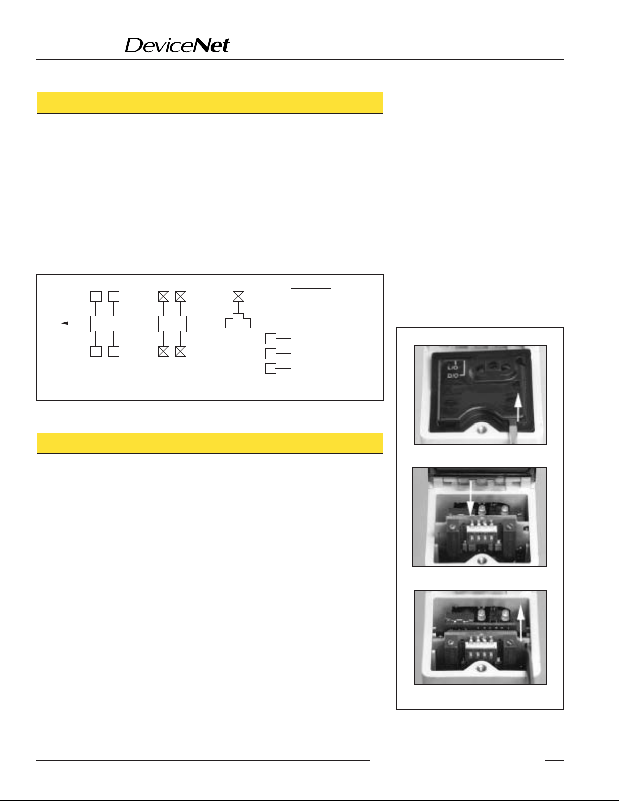
Figure 1. The same model Q45X “smart” and “dumb” sensors may be mixed on the same
bus system
A. Lift here
B. Slide board downward
C. Lift board up and out
Figure 2. Installation and removal of Bus
Expansion Cards
“Smart” sensor
Q45XQ45XQ45XQ45XQ45X
PLC
us
Smart
Drop
Q45X Q45X Q45X Q45X
“Dumb” Sensors
(x4)
Dumb
Drop
“Smart” Sensors
(x4)
“T”
Connector
Q45X
Q45X
Q45X
“Dumb” Sensors
(x3)
Data
Input
Input
Input
Page 3

The Q45X sensor with 45DN expansion card installed requires DeviceNet-compatible
quick-disconnect cable, which is available from various manufacturers, such as
interlinkBT. See table at left.
Q45XDN
™
P/N 39667 rev. C 3
Banner Engineering Corp. • Minneapolis, MN U.S.A.
www.bannerengineering.com • Tel: 763.544.3164
Q45X Base, Male Connector
Hookup
Figure 3. Q45X Bus Configuration (45DN card installed)
1
5
4
3
2
Shield
Communications -
Communications +
BUS power (-V)
BUS power (-V)
Blue
White
Black
Red
Pin Function
Wire
Color*
*Wire colors in the table above are for
DeviceNet-compatible cable only.
Specifications – Q45X Series Sensors using 45DN Expansion Cards*
Supply Protection Circuitry Protected against reverse polarity, transient voltages and loss of ground
(none of these conditions will harm the sensor or interrupt communication on the network)
Response Time 2 milliseconds; total response time will also include the response time of the network
Indicators On the sensor: Green and Red; visible through the transparent sensor top cover
Green LED lights for dc power “ON”
Red LED(except emitter model Q45X6EQ) is Banner's patented Alignment Indicating Device (AID
™
,
U.S. patent #4356393) which lights whenever the sensor “sees” a light condition and superimposes a
pulse rate which is proportional to the strength of the received light signal (the stronger the signal, the
faster the pulse rate)
On the 45DN1 and 45DN2 Bus Cards: Green and Red; visible through the transparent sensor top cover
A bi-color LED indicates the status of the network.
Green Steady Sensor on line, connected to master
Flashing Sensor on line - address + baud rate are ok
Red Steady Critical network fault or duplicate node address detected; wrong baud rate
Flashing Minor or connection time-out fault
Operating Conditions Temperature: -10° to +70°C (-14° to +158°F)
Relative humidity: 95% (non-condensing)
Supply Voltage and Current 11 to 25V dc @ 60 mA (combined current for Q45X sensor and 45DN card)
* See Q45X datasheet P/N 37735 for further information.
1
5
2
4
3
Page 4

Banner Engineering Corp., 9714 Tenth Ave. No., Minneapolis, MN 55441 • Phone: 763.544.3164 • www.bannerengineering.com • Email: sensors@baneng.com
Q45XDN
™
WARRANTY: Banner Engineering Corp. warrants its products to be free from defects for one year. Banner Engineering Corp. will repair or
replace, free of charge, any product of its manufacture found to be defective at the time it is returned to the factory during the warranty period.
This warranty does not cover damage or liability for the improper application of Banner products. This warranty is in lieu of any other warranty
either expressed or implied.
P/N 39667 rev. C
 Loading...