

Page 1
DIFFUSE
RETRO
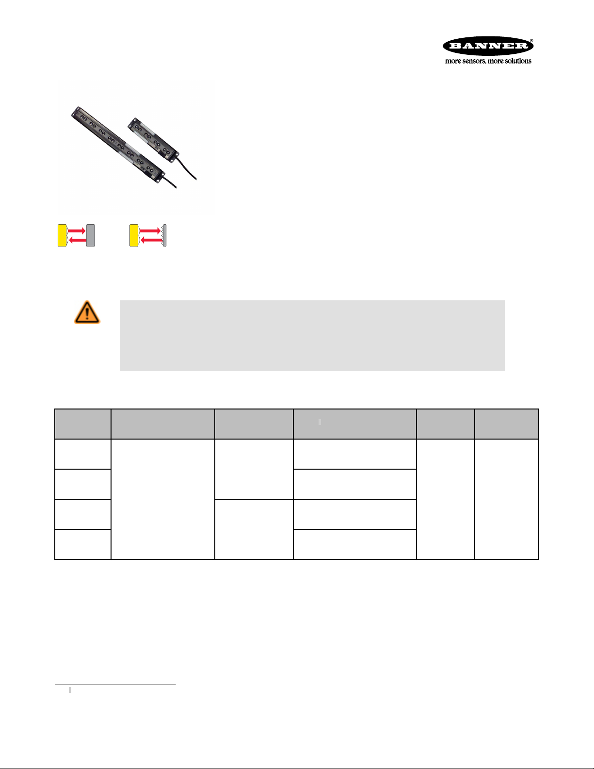
PVD Series Parts Verification Sensor
Diffuse or retroreflective sensor for error proofing of bin-picking operations
• One-component system, easy to mount and even easier to use. Automatically operates in
either diffuse or retroreflective mode, depending on the application
• Automatic setup and adjustment; wide beam pattern provides easy alignment
• Range up to 2 m (6.5 ft) when used with retroreflective target; 400 mm (15.7 in) when used
in diffuse mode
• Large job lights on either side of the metal housing can be remotely controlled to initiate
user action with a solid or a blinking green light; job lights turn red to indicate bin-picking
errors
• Compact package size; only 30 mm wide x 15 mm deep (1.2 in x 0.6 in)
• Available in 2 lengths to fit existing parts bin sizes and configurations
• Easy DIP-switch adjustments: PNP/NPN output, normally open/normally closed operation,
solid/flashing job light, and gate polarity for job light activation
• Two LEDs indicate power ON and output ON
• Choose 2 m (6.5 ft) unterminated cable or 2 m (6.5 ft) cable with 5-pin Euro-style quick-
Visible Red, 630 nm
Patent(s) issued or pending
WARNING: Not To Be Used for Personnel Protection
Never use this device as a sensing device for personnel protection. Doing so could lead to serious
injury or death. This device does not include the self-checking redundant circuitry necessary to allow its
use in personnel safety applications. A sensor failure or malfunction can cause either an energized or deenergized sensor output condition.
disconnect connector
• Heavy-duty protective brackets available
• 12 to 30V dc operation
Models
Models Range Array Cable
PVD100
PVD100Q
PVD225
PVD225Q
Retroreflective Mode: up
to 2 m (6.5 ft)
Diffuse Mode: up to 400
mm (15.7 in)
All models may be used in
either sensing mode.
100 mm (4 in) long,
4 beams
225 mm (9 in) long,
8 beams
2 m (6.5 ft) 5-wire cable, unterminated
2 m (6.5 ft) cable, terminated in
a QD connector
2 m (6.5 ft) 5-wire cable, unterminated
2 m (6.5 ft) cable, terminated in
a QD connector
1
Supply Voltage
12 to 30V dc
Output
User-selectable
NPN/PNP
Overview
The PVD Series Parts Verification Sensor is a one-component, easy-to-use light screen suited to many part assembly, bin picking (pickto-light), and error-proofing applications. The PVD increases task efficiency due to simplified job training, increased quality control (no
skipped components), and reduced rework and inspections. It speeds the resumption of work after breaks and other distractions, and is
ideal for multilingual workplaces where communication is an issue.
The PVD self-contained, solid-state emitter/receiver array is capable of functioning in either diffuse or retroreflective sensing mode. No
configuration is required for this selection. If a retroreflective target is installed opposite the sensor, it will function in retroreflective mode.
If not, it will function in diffuse mode. The sensor’s ongoing self-adjustment feature requires no user adjustment; the sensor adapts to the
sensing conditions after 15 seconds when blocked. Sensor range decreases when no retroreflector is installed.
1
• 9 m (30 ft) cables are available by adding suffix “W/30” to the model number of any cabled sensor (for example, PVD100 W/30)
• 150 mm (6 in) cable terminated in a QD connector available by adding “W/6IN” to model number of any terminated sensor (for example, PVD100Q W/6IN). A model with a QD
connector requires a mating cable; see Cordsets on page 7.
P/N 113230_web
Rev. E
6/26/2013
Page 2
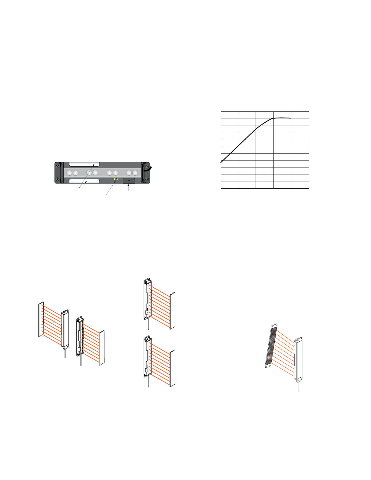
MODE
Status
Indicators
Configuration
Switch Cover
Job Lights
(Error Lights)
0
0
10 mm
20 mm
30 mm
40 mm
50 mm
60 mm
70 mm
80 mm
90 mm
100 mm
110 mm
2.5 m
2 m
1.5 m1 m0.5 m
Range
Minimum Object Size
to Always Block a Beam
Sensor
Reflector
Reflector
Sensor
MODE
MODE
Sensor
Sensor
Reflector
Reflector
MODE
PVD Series Parts Verification Sensor
The DIP-switch-selectable PNP/NPN output interfaces to a system controller, which is pre-programmed for a specific sequence of tasks.
Mounted with its visible red beams stretching across each parts bin, the sensor job light signals the assembler which bins contain items
to be picked in a given operation and in what order they should be picked.
As the assembler takes a part in sequence and breaks the beam, the sensor senses that the part was removed and it sends an output
signal to the controller. The controller then verifies if the correct part was taken and may respond by turning that job light OFF, activating
the job light of the next bin in the sequence. If the assembler reaches into a bin out of sequence, the PVD turns on its output to signal the
system controller and turns on its red job light to signal the assembler that an incorrect pick has occurred.
Standard configuration options are selected by means of a bank of four DIP switches behind a press-on black rubber cover. DIP switch
options include: PNP or NPN output, Normally Open or Normally Closed operation, steady or flashing job light, and job light control input.
Figure 1. Sensor features
Figure 2. Minimum object detection size (retroreflective operation)
Installation
Multiple sensors located farther than the sensor's maximum range from one another are unlikely to cause crosstalk problems. However,
when multiple sensors are mounted in a confined area, take care to avoid crosstalk between them. Alternate the relative position of
adjacent sensors and/or reflectors. Sensors positioned above or below one another should not create crosstalk difficulties. Mount the
sensor and reflector parallel.
Figure 3. Examples of Appropriate Positions Figure 4. Example of Incorrect Position
2 www.bannerengineering.com - tel: 763-544-3164 P/N 113230_web
Rev. E
Page 3
MODE
Job Light Control
Not Used
2
5
12-30V dc
–
+
1
3
4
Load
12-30V dc
Job Light Control
Not Used
–
+
1
3
2
4
5
Load
PVD Series Parts Verification Sensor
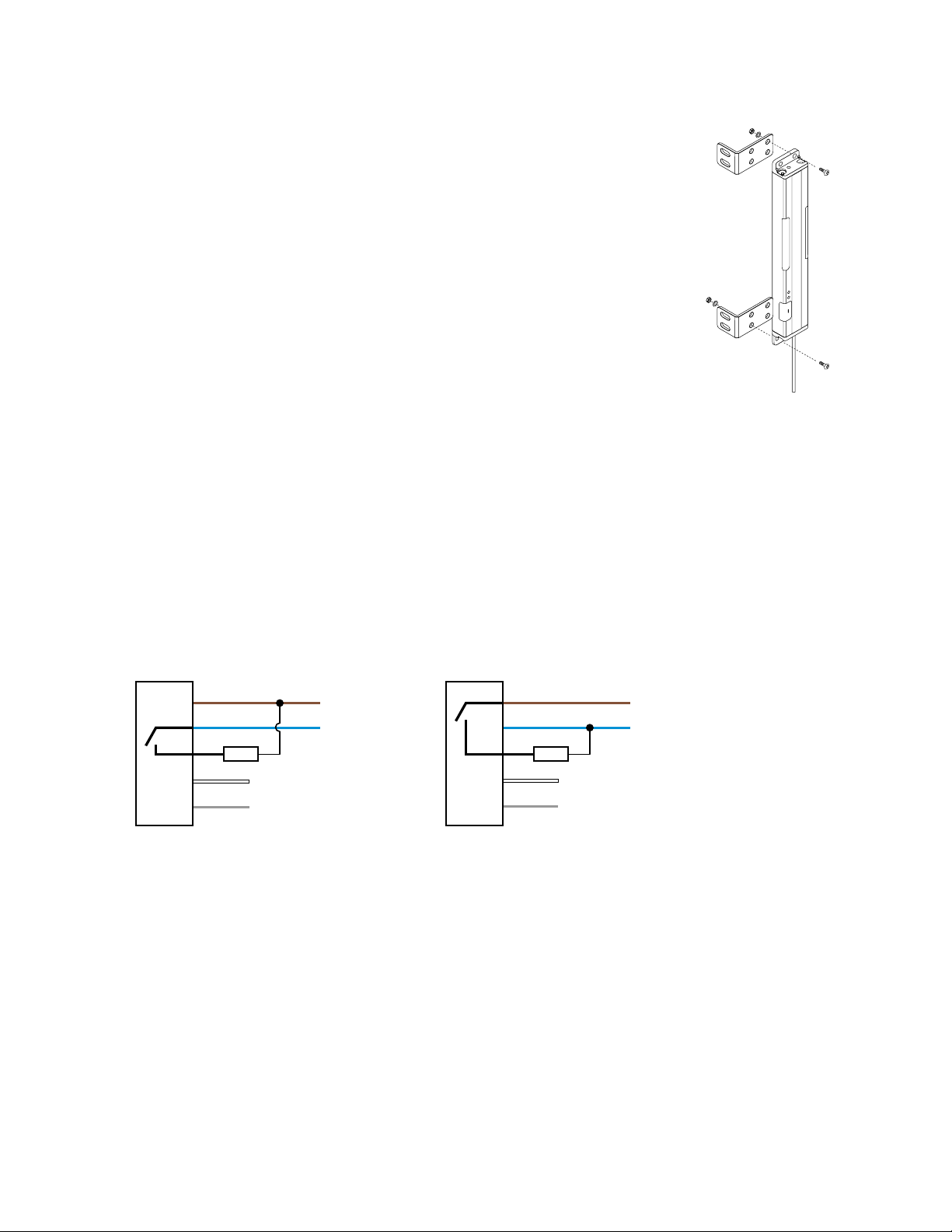
Mounting
The wide beam pattern of PVD sensors simplifies their alignment. M4 stainless steel fasteners
and two stainless steel brackets are included with each sensor.
Mount the sensor and its reflector, if used, parallel to one another in the same plane, and their
tops and bottoms aligned.
1. From a common point of reference, make measurements to locate the sensor and its reflector, if used, in the same plane with their midpoints directly opposite each other.
2. Mount the included brackets to the top and bottom of each sensor, as shown.
3. Mount the sensor in its brackets and the reflector, if used, being careful to position the sensor's red lenses directly facing the reflector.
4. Measure from one or more reference planes (for example, the building or bin floor) to the
same point(s) on the emitter and receiver to verify their mechanical alignment. (If the sensors/reflectors are mounted exactly vertical or horizontal, a carpenter’s level may be helpful.
A straightedge or a string extended between the sensor and the bin wall may also be helpful.)
5. Also check “by eye” for line-of-sight alignment.
6. Make any necessary final mechanical adjustments, and hand-tighten the bracket hardware.
7. After the electrical hookup is complete, check for beam alignment. If necessary, re-align the
emitter and receiver at that time.
Figure 5. PVD Mounting Hard-
ware
Hookups
All models feature integral 2 m (6.5 ft) long, 3.3 mm (0.13 inch) dia. PVC-jacketed cables. Models whose model numbers end in “Q” are
terminated with quick-disconnect (QD) Euro-style 5-pin connectors; other models have unterminated ends. Optional mating QD cables
are available. Either 4-pin or 5-pin QD cables may be used; the center pin of a 5-pin cable (gray wire, pin 5) is unused in normal operation.
Wiring is functionally identical for cabled and quick-disconnect models.
NPN (Sinking) Output PNP (Sourcing) Output Key
1 = Brown
2 = White
3 = Blue
4 = Black
5 = Gray
See Configuration on page 4 for job light control input requirements.
P/N 113230_web
Rev. E
www.bannerengineering.com - tel: 763-544-3164 3
Page 4

1 2 3 4
O
F
F
O
N
ON
OFF
Example Shown:
Switch #1 OFF
Switch #2 ON
Switch #3 OFF
Switch #4 ON
PVD Series Parts Verification Sensor
Configuration
To configure the PVD, set the DIP switches as shown, using the supplied plastic screwdriver to avoid damaging the switches or causing a
short circuit.
Cover Removal Cover Replacement
Insert a fingernail or small screwdriver into
the slot; apply gentle pressure, angling
To replace the switch cover, align one edge of the cover with the edge of the sensor
housing opening. Then press the front corners into place.
away from the sensor lens. The cover will
remain tethered to the sensor housing.
The switches determine four status operating modes:
PVD Configuration DIP Switch Settings
The factory default setting is ON for all switches
Figure 6. Configuration DIP switch setting posi-
tions
Switch Condition
1 ON = PNP output
OFF = NPN output
2 ON = Normally Open
OFF = Normally Closed
3 ON = Job light steady
OFF = Job light flashes
4 Job light control input: Connect the white wire as follows:
PNP Output
ON = Job light ON for +10 to 30V dc (29kΩ input impedance)
OFF = Job light ON for 0 to 1.5V dc/open circuit
NPN Output
ON = Job light ON for +10 to 30V dc/open circuit
OFF = Job light ON for 0 to 1.5V dc (10kΩ input impedance)
4 www.bannerengineering.com - tel: 763-544-3164 P/N 113230_web
Rev. E
Page 5

MODE
Status Indicator #1
Status Indicator #2
PVD Series Parts Verification Sensor
Status Indicators/Troubleshooting
Figure 7. Status indicators
Indicator Condition Description
#1 Steady Yellow Output is active (Changing Switch #2 to N.C. turns the yellow indicator ON when the system is clear)
OFF Output is inactive (Changing Switch #2 to N.O. turns the yellow indicator ON when the system is blocked)
#2 Steady Green Power is ON and system is OK
Flashing Green Blanking is enabled
OFF Power is OFF
Specifications
Supply Voltage and Current
Input Voltage: 12 to 30V dc (10% maximum ripple at
10% duty cycle)
Input Current: Less than 40 mA @ 24V dc and less
than 70 mA @ 12V dc (exclusive of load)
Supply Protection Circuitry
Protected against reverse polarity and transient overvoltages
Sensing Beam
Visible red, 630 nm
Sensing Range
Retroreflective applications: 2 m (6.5 ft) using 25
mm (1 in) wide retroreflective tape
Diffuse applications: 400 mm (15.7 in) with 18% re-
flectivity gray card target
Sensing Height
4-channel models: 111 mm (4.4 in)
8-channel models: 240 mm (9.4 in)
Beam Spacing
28.6 mm (1.125 in)
Output Configuration
User-selectable via DIP switch:
1 open-collector PNP (current sourcing) or 1 open-col-
lector NPN (current sinking)
Sensing Resolution
See Dimensions on page 6 for Minimum Object Detection Zone
Retroreflective: 51 mm at 406 mm range, 100 mm at
2 m (2.0 in dia. at 16 in range, 3.9 in at 6.5 ft); see
Figure 2. Minimum object detection size (retroreflective
operation) on page 2
Diffuse: 55 mm dia. at 400 mm range (2.16 in at 15.7
in range)
Indicators
Green LED: Power ON/OFF
Yellow LED: Output ON/OFF
Job Light (Diffused Green LED): Turned ON and OFF
by applying an external signal to the Job input (white
wire). The job lights will be active high or active low,
depending on DIP switch 4 selection.
Error Light (Diffused Red LED): Turned ON and OFF
by detection of an output event when job light is not
ON.
Adjustments
4 DIP switches, located behind access panel (default
setting is ON position)
Construction
Black painted aluminum housing; acrylic lenses; thermoplastic polyester end caps; thermoplastic elastomer
programming switch cover; stainless steel mounting
brackets and hardware
P/N 113230_web
Rev. E
www.bannerengineering.com - tel: 763-544-3164 5
Page 6

MODE
MODE
266.4 mm
(10.49")
258.6 mm
(10.19")
71.8 mm
(2.83")
43.2 mm
(1.70")
4 x ø4.45 mm
(0.175")
15.0 mm
(0.59")
30.0 mm
(1.18")
Cable
18.0 mm
(0.71")
137.8 mm
(5.43")
130.0 mm
(5.12")
3.9 mm
(0.15")
3.9 mm
(0.15")
4 x ø4.45 mm
(0.175")
18.0 mm
(0.71")
21.1 mm
(0.83")
22.1 mm
(0.83")
29.2 mm
(1.15")
29.2 mm
(1.15")
Minimum Object Detection Zone
Minimum Object Detection Zone
1.4 mm
(0.06")
PVD Series Parts Verification Sensor
Output Rating
150 mA maximum
OFF-state leakage current: less than 10 microamps
ON-state saturation voltage: NPN — less than 1V dc at
150 mA; PNP — less than 2V dc at 150 mA
Output Protection
Protected against false pulse on power-up and short
circuit of outputs
Output Response Time
400 ms (includes standard 100 ms ON-delay and 100
ms OFF-delay)
Delay at Power-Up
Less than 1.0 second
Dimensions
Connections
5-conductor PVC-jacketed 2 m (6.5 ft) cable which is
either unterminated or terminated with a 5-pin Eurostyle quick-disconnect connector, depending on model.
Cable diameter is 3.3 mm (0.13 in).
Environmental Rating
NEMA 2; IEC IP62
Operating Conditions
Temperature: 0 °C to +50 °C (+32 °F to +122 °F)
Humidity: 90% at +50 °C maximum relative humidity
(non-condensing)
Certifications
6 www.bannerengineering.com - tel: 763-544-3164 P/N 113230_web
Rev. E
Page 7

40.6 mm
(1.60")
6.0 mm
(0.24")
6.0 mm
(0.24")
20.1 mm
(0.79")
18.0 mm
(0.71")
4 x ø4.6 mm
(0.18")
6.1 mm
(0.24")
2.0 mm
(0.08")
4 x R2.54
(0.10")
10.2 mm
(0.40")
10.2 mm
(0.40")
5.0 mm
(0.20")
5.0 mm
(0.20")
2 x 4.8 mm
(0.19")
22.9 mm
(0.90")
44 Typ.
ø 14.5
M12 x 1
2
3
4
1
44 Typ.
ø 14.5
M12 x 1
2
3
4
1
5
PVD Series Parts Verification Sensor
SMBPVA1 Standard Bracket (2 Included with PVD) Hardware Included with Each Sensor (kit part
number 50532)
Qty Description
4 Stainless steel Phillips panhead ma-
chine screws (M4 x 0.7 x 12)
2 Stainless steel Phillips panhead ma-
chine screws (M4 x 0.7 x 6)
2 Stainless steel Phillips panhead ma-
chine screws (M4 x 0.7 x 18)
4 Stainless steel hex nuts (M4 x 0.7)
4 Stainless steel lock washers (M4 x 0.7)
1 Plastic screwdriver (3.6 cm/1.4 in long)
Accessories
Cordsets
4-Pin Threaded M12/Euro-Style Cordsets
Model Length Style Dimensions Pinout
MQDC-406 1.83 m (6 ft)
MQDC-415 4.57 m (15 ft)
MQDC-430 9.14 m (30 ft)
Straight
MQDC-450 15.2 m (50 ft)
5-Pin Threaded M12/Euro-Style Cordsets (Single Ended)
Model Length Style Dimensions Pinout (Female)
MQDC1-501.5 0.50 m (1.5 ft)
MQDC1-506 1.83 m (6 ft)
MQDC1-515 4.57 m (15 ft)
Straight
MQDC1-530 9.14 m (30 ft)
www.bannerengineering.com - tel: 763-544-3164 7
P/N 113230_web
Rev. E
1 = Brown
2 = White
3 = Blue
4 = Black
1 = Brown
2 = White
3 = Blue
4 = Black
5 = Gray
Page 8

L
35.7 mm
(1.40 in.)
21.2 mm
(0.83 in.)
21.2 mm
(0.83 in.)
L
35.7 mm
(1.40 in.)
16
6 x Ø4.8
4 x Ø5.2
2 x Ø7.3
41
L
PVD Series Parts Verification Sensor
Brackets
All measurements are listed in millimeters.
Bracket Selection Table
Bracket Model Requires Use of
Bracket Model(s)
SMBPVD1
(included with
N.A.
PVD System)
SMBPVD100A(B)
SMBPVD225A(B)
N.A.
SMBPVA5C
SMBPVA10C
N.A.
NOTE: Standard mounting brackets are included with each PVD System. The following brackets are in addition to the standard brackets.
May Be Used with
Bracket Model(s)
SMBPVD100A(B)
SMBPVD225A(B)
SMBPVA2
SMBPVD1
SMBPVA5(10)
SMBPVA9
SMBPVA2
SMBPVD100A(B)
SMBPVD225A(B)
SMBPVA7
SMBPVA8
Bracket Model Requires Use of
Bracket Model(s)
SMBPVA9
SMBPVA2
N.A.
N.A.
SMBPVA7 SMBPVA5C
or
SMBPVA10C
SMBPVA8 SMBPVA5C
or
SMBPVA10C
May Be Used with
Bracket Model(s)
SMBPVD100A(B)
SMBPVD225A(B)
SMBPVD100A(B)
SMBPVD225A(B)
SMBPVD100A(B)
SMBPVD225A(B)
SMBPVD100A(B)
SMBPVD225A(B)
SMBPVD..A & SMBPVD..AB
• Heavy-duty protection brackets
• Some models include DIPswitch access port
• Cold-rolled steel with zinc finish
• May be used with SMBPVA..C
for mounting to SMBPVA7 or
SMBPVA8 brackets
Models with DIP
Switch Access
Models with No DIP
Switch Access
L
Port
SMBPVD100A SMBPVD100AB 140 mm (5.5
in)
SMBPVD225A SMBPVD225AB 269 mm
(10.6 in)
SMBPV..C
• Back-mounted bracket for
mounting to SMBPVA7 or
SMBPVA8 brackets
• Cold-rolled steel with zinc
finish
Model L
SMBPVA5C 170.0 mm
SMBPVA10C 298.5 mm
8 www.bannerengineering.com - tel: 763-544-3164 P/N 113230_web
Rev. E
Page 9

A
B
C
32
51
41
65
33
A
B
PVD Series Parts Verification Sensor
SMBPVA2
• Set of 4 molded brackets
• Snaps onto standard 28
mm (1.1 in) diameter pipe
• 2 required per sensor
SMBPVA8
• Heavy-duty 2-part bracket
mounts to 28 mm (1.1 in)
diameter pipe
• Cold-rolled steel with zinc
finish
• Requires SMBPVA..C for
mounting
A=ø 30.5, B=ø 7.1
Retroreflective Tape
SMBPVA7
• One-piece bracket for
mounting to 28 mm (1.1 in)
diameter pipe
• Black-painted steel
• Requires SMBPVA..C for
mounting at an angle ±90°
A = M4 x 0.5, B = ø 5.2, C = ø 4.2
SMBPVA9
• Pair of two-piece swivel
brackets
• Mount directly to sensor or
to PVD or PVA protective
brackets
• Designed for mounting
sensor to "look down"
Model Reflectivity Factor Maximum Temperature Size
BRT-THG-1-100 0.7 +60 °C (+140 °F) 25 mm (1 in) wide, 2.5 m (100 in) long
BRT-THG-2-100 0.7 +60 °C (+140 °F) 50 mm (2 in) wide, 2.5 m (100 in) long
BRT-THG-3-100 0.7 +60 °C (+140 °F) 75 mm (3 in) wide, 2.5 m (100 in) long
Banner Engineering Corp Limited Warranty
Banner Engineering Corp. warrants its products to be free from defects in material and workmanship for one year following the date of
shipment. Banner Engineering Corp. will repair or replace, free of charge, any product of its manufacture which, at the time it is returned
to the factory, is found to have been defective during the warranty period. This warranty does not cover damage or liability for misuse,
abuse, or the improper application or installation of the Banner product.
THIS LIMITED WARRANTY IS EXCLUSIVE AND IN LIEU OF ALL OTHER WARRANTIES WHETHER EXPRESS OR IMPLIED (INCLUDING, WITHOUT LIMITATION, ANY WARRANTY OF MERCHANTABILITY OR FITNESS FOR A PARTICULAR PURPOSE), AND
WHETHER ARISING UNDER COURSE OF PERFORMANCE, COURSE OF DEALING OR TRADE USAGE.
This Warranty is exclusive and limited to repair or, at the discretion of Banner Engineering Corp., replacement. IN NO EVENT SHALL
BANNER ENGINEERING CORP. BE LIABLE TO BUYER OR ANY OTHER PERSON OR ENTITY FOR ANY EXTRA COSTS, EXPENSES, LOSSES, LOSS OF PROFITS, OR ANY INCIDENTAL, CONSEQUENTIAL OR SPECIAL DAMAGES RESULTING FROM ANY
PRODUCT DEFECT OR FROM THE USE OR INABILITY TO USE THE PRODUCT, WHETHER ARISING IN CONTRACT OR WARRANTY, STATUTE, TORT, STRICT LIABILITY, NEGLIGENCE, OR OTHERWISE.
Banner Engineering Corp. reserves the right to change, modify or improve the design of the product without assuming any obligations or
liabilities relating to any product previously manufactured by Banner Engineering Corp.
www.bannerengineering.com - tel: 763-544-3164
 Loading...