

Page 1
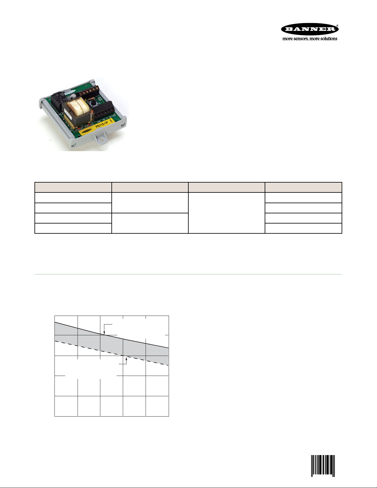
25
20
20 40 60 80 100
15
10
5
0
0
Load Current dc (milliamps)
V Output (dc)
NOTE: Ripple voltage is less than 1.2V at 100 mA load
Minimum AC Input Voltage
21V ac (PS24-1..)
105V ac (PS115-1..)
Maximum AC Input Voltage
27V ac (PS24-1..)
130V ac (PS115-1..)
PS24-1 and PS115-1 Sensor Interface
0 123566 1
Power Supplies
Datasheet
• Low-cost interface between ac power supply and dc-operated
sensors
• Power supply can source up to 100 milliamps
• Integral TEACH push button and remote TEACH function available
on all models
• Integral SPDT relay isolates dc sensor output for ac applications
• LED indicators for Power ON and Output Active
• Easy-to-adjust 45° screw terminals for all electrical wiring
• Multiple mounting configurations using supplied hardware
• BENC-L enclosure available for NEMA 4X / IP55 applications
• Use a sinking (NPN) interface module model with an NPN-output
sensor, and a sourcing (PNP) interface module model with a PNP-
Optional mounts, plastic housing and
brackets included.
output sensor.
Models
PS24-1N
21 to 27V ac, 50/60 Hz
PS24-1P Sourcing (PNP)
PS115-1N
105 to 130V ac, 50/60 Hz
PS115-1P Sourcing (PNP)
A sinking (NPN) interface module model must be used with an NPN-output sensor, and a sourcing (PNP) interface module
model must be used with a PNP-output sensor.
Input Output Relay Input
Sinking (NPN)
100 mA
Sinking (NPN)
Overview
This interface module combines the functions of a power supply, a TEACH button, and an SPDT relay to economically
interface dc-operated sensors for ac applications. The interface accepts either a 24V ac or 115V ac power supply,
depending on the model. It uses a transformer to isolate the input power supply from the dc sensor. The transformer
output voltage is rectified and filtered to supply up to 100 milliamps to run dc sensors.
An integral TEACH button can be used to activate the
TEACH functions of a Banner Expert™ sensor. Remote
TEACH capability also is available on all models (refer to
hookup diagrams and sensor literature).
The SPDT relay is controlled via the relay coil input. A dc
sensor output (either sinking or sourcing, depending on
interface module model) can be tied to the relay coil input.
The module's amber LED is ON when the sensor output is
active. The module's green LED is used as a power
indicator.
For sensor supply voltage and current requirements, refer
to the chart.
P/N 123566 Rev. C 9 Oct 2013
Page 2
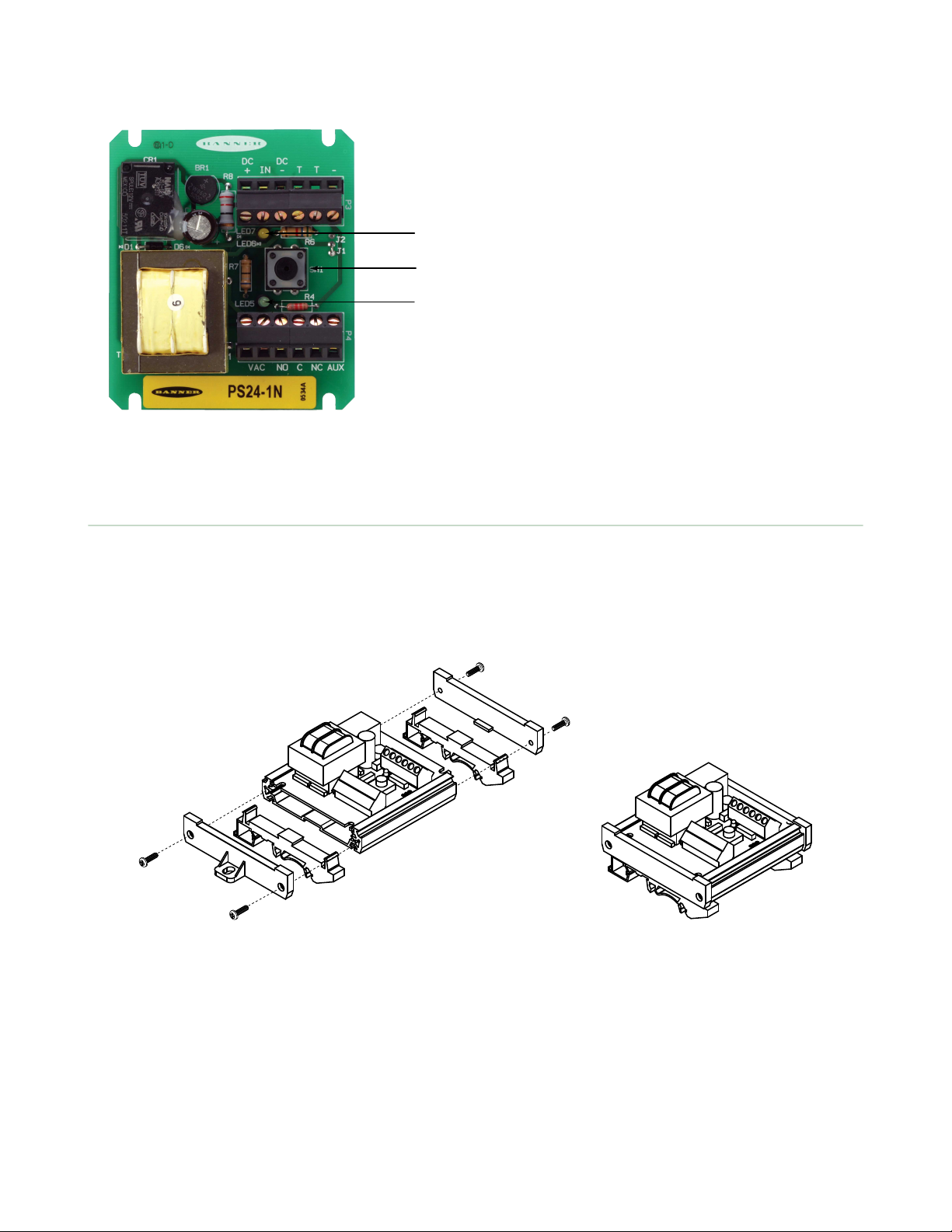
1
2
3
PS24-1 and PS115-1 Sensor Interface Power Supplies
1. Output Indicator LED (amber)
2. TEACH button
3. Power Indicator LED (green)
Installing the PS24-1 or PS115-1 Power Supply
The module must be isolated from conductive surfaces. It may be installed in a user-supplied housing using the four slots
in the board’s corners, or it may be inserted into the supplied plastic housing.
When you use the supplied housing, either insert the two DIN clips into the grooves on the housing’s underside and add
the two end caps (shown), or install only the end caps and use the screw-holes in the end caps for mounting to a flat
surface. Screws are provided for attaching the end caps to the housing.
2 www.bannerengineering.com - tel: 763-544-3164 P/N 123566 Rev. C
Page 3

2X 57.2 mm
[2.25"]
2X 3.3 mm [0.13"]
4X R1.8 mm
[R 0.07"]
82.5 mm
[3.25"]
31.7 mm
[1.25"]
72.4 mm [2.85"]
2X 2.7 mm (0.11")
102.5 mm
(4.04")
111.7 mm
(4.40")
2X 11.8 mm (0.46")
43.2 mm
(1.70")
78.7 mm
(3.10")
2X R 2.7 mm
(R 0.11")
61.5 mm
(2.42")
44.4 mm
(1.75")
86.4 mm (3.40")
PS24-1 and PS115-1 Sensor Interface Power Supplies
Specifications
Input Supply Voltage
PS24-1: 21–27V ac, 47/63 Hz
PS115-1: 105–130V ac, 47/63 Hz
Voltage and Current Output Rating
100 mA, exclusive of relay coil input; see load
curves
Relay Input Voltage Range
12–30V dc
Relay Input Resistance
470 ohms ±10%
Indicators
Green LED: Power applied
Amber LED: Relay coil energized (output active)
Construction
Circuit board is shipped separate from housing.
Plastic housing, end caps and DIN rail mounting
hardware are supplied for user assembly.
Connections
Screw-clamp terminal block accepts 12–24 gauge
wire
Dimensions
Module
Relay Output Rating
SPDT Relay
Maximum Switched Power: 150W, 1200VA
Maximum Switched Current: 5A (resistive load)
Maximum Switched Voltage: 30V dc, 250V ac
Minimum Current and Voltage: 10 mA at 5V dc
Mechanical Life: 10,000,000 operations
Electrical Life: 100,000 operations at full load
Relay Response Time
10 milliseconds
Adjustments
TEACH button
Environmental Rating
IP00; use BENC-L enclosure for NEMA 4X / IP55
rating.
Operating Conditions
Temperature: –40 to 70 °C (–40 to 158 °F)
Max. Relative Humidity: 90% at 50 °C (122 °F)
(non-condensing)
Certifications
CSA and UL approvals pending
With Plastic Housing Assembly
P/N 123566 Rev. C www.bannerengineering.com - tel: 763-544-3164 3
Page 4

PS24-1P
PS115-1P
AC
AC
N.O.
N.C.
C
AUX*
V+
V–
Teach
Teach
Remote
Teach
Sourcing Output
IN
T
T
–
+
–
DC Sensor
Relay
Coil
PS24-1N
PS115-1N
AC
AC
N.O.
N.C.
C
AUX*
V+
V–
Teach
Teach
Remote
Teach
Sinking Output
IN
T
T
–
+
–
Relay
Coil
DC Sensor
127.8 mm
[5.03"]
2x 1/2" NPSM thread
167.4 mm
[6.59"]
148.1 mm
[5.83"]
59.3 mm
(2.34")
55.9 mm
[2.20"]
87.6 mm
[3.45"]
2xS Ø 8.3 mm
[0.33"]
4x 1/4"-20 x 30
Screws
4X #8 Self-tapping
Screw
PS24-1.. or
PS115-1.. Module
(Order separately)
O-Ring
PS24-1 and PS115-1 Sensor Interface Power Supplies
Hookup Diagrams
PNP Input NPN Input
Accessories
BENC-L
• Corrosion-resistant plastic enclosure with
clear polycarbonate cover to protect
module
• Rated NEMA 4X, IP55
• Includes o-ring and 4 each: 1/4"-20x30
and #8 self-tapping screws
• Temperature rating –40 to 70 °C (–40 to
158 °F)
* AUX is an electrically isolated terminal.
Banner Engineering Corp Limited Warranty
Banner Engineering Corp. warrants its products to be free from defects in material and workmanship for one year following
the date of shipment. Banner Engineering Corp. will repair or replace, free of charge, any product of its manufacture
which, at the time it is returned to the factory, is found to have been defective during the warranty period. This warranty
does not cover damage or liability for misuse, abuse, or the improper application or installation of the Banner product.
THIS LIMITED WARRANTY IS EXCLUSIVE AND IN LIEU OF ALL OTHER WARRANTIES WHETHER EXPRESS OR
IMPLIED (INCLUDING, WITHOUT LIMITATION, ANY WARRANTY OF MERCHANTABILITY OR FITNESS FOR A
PARTICULAR PURPOSE), AND WHETHER ARISING UNDER COURSE OF PERFORMANCE, COURSE OF DEALING OR
TRADE USAGE.
This Warranty is exclusive and limited to repair or, at the discretion of Banner Engineering Corp., replacement. IN NO
EVENT SHALL BANNER ENGINEERING CORP. BE LIABLE TO BUYER OR ANY OTHER PERSON OR ENTITY FOR
ANY EXTRA COSTS, EXPENSES, LOSSES, LOSS OF PROFITS, OR ANY INCIDENTAL, CONSEQUENTIAL OR
SPECIAL DAMAGES RESULTING FROM ANY PRODUCT DEFECT OR FROM THE USE OR INABILITY TO USE THE
PRODUCT, WHETHER ARISING IN CONTRACT OR WARRANTY, STATUTE, TORT, STRICT LIABILITY,
NEGLIGENCE, OR OTHERWISE.
Banner Engineering Corp. reserves the right to change, modify or improve the design of the product without assuming any
obligations or liabilities relating to any product previously manufactured by Banner Engineering Corp.
www.bannerengineering.com - tel: 763-544-3164
 Loading...