

Page 1

STB Self-Checking Optical Touch Buttons
Datasheet
• Continuous internal self-checking operation
• Diverse-redundant microcontroller-based photoelectric touch
buttons
• Ergonomically designed to eliminate hand, wrist and arm
stresses associated with repeated switch operation; require no
physical pressure to operate
• High excess gain cuts through heavy contamination
• Immune to ambient light, EMI and RFI interference
• LED power, output and fault indicators
• Yellow field cover included
U.S. Patent(s) issued or pending
Model Cable
STBVP6
STBVP6Q
STBVP6Q5 4-Pin Euro-style QD
STBVR81
STBVR81Q 5-Pin Mini-style QD
STBVR81Q6 5-Pin Euro-style QD
Standard 2 m (6.5 ft) cable models are listed. To order the 9 m (30 ft) cable model, add suffix "W/30" to the cabled model
number. For example, STBVP6 W/30. Models with a QD connector require a mating cable.
4-wire 2 m (6.5 ft) integral
cable
4-Pin Mini-style QD
5-wire 2 m (6.5 ft) integral
cable
WARNING:
Not a Stand-Alone Safety Device. STB Series Touch Buttons are self-checking ergonomic actuating
devices, but are not, by themselves, safety devices. To be used in a safety application, two STBs must
be interfaced with a type IIIC two-hand-control module, such as the Banner AT-FM-10K, to meet all
relevant safety requirements of the appropriate standards (e.g., ISO13851 / EN574).
Supply
Voltage
10–30V dc
20–30V ac/dc
Output Type
Complementary
PNP
Two Individual
Complementary
Relays
DUO-TOUCH® SG
Compatibility
AT-FM-10K, AT-GM/HM-13A, and
AT-GM/HM-11KM Two-Hand
Control Modules, and SC22-3
Safety Controller
Important - Read This Before Proceeding
The user is responsible for satisfying all local, state, and national laws, rules, codes, and regulations relating to
the use of this product and its application. Banner Engineering Corp. has made every effort to provide complete
application, installation, operation, and maintenance instructions. Please direct any questions regarding the use or
installation of this product to the factory applications department at the telephone numbers or address found at http://
www.bannerengineering.com.
The user is responsible for making sure that all machine operators, maintenance personnel, electricians, and
supervisors are thoroughly familiar with and understand all instructions regarding the installation, maintenance, and use of
this product, and with the machinery it controls. The user and any personnel involved with the installation and use of this
product must be thoroughly familiar with all applicable standards, some of which are listed within the specifications.
Banner Engineering Corp. makes no claim regarding a specific recommendation of any organization, the accuracy or
effectiveness of any information provided, or the appropriateness of the provided information for a specific application.
Applicable U.S. Standards
ANSI B11 Standards for Machine Tools Safety
P/N 64136 Rev. C 4 December 2013
Page 2
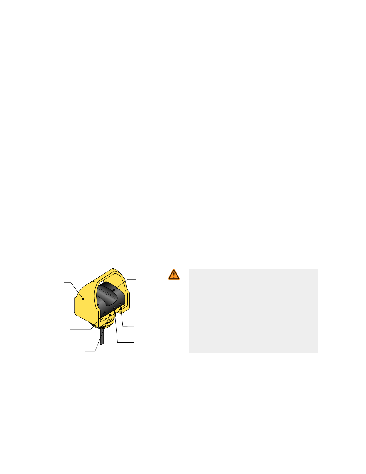
Yellow
Polypropylene
Field Cover
Black Polyetherimide
Output
Fault
LED
Power
ON/OFF
LED
Switch
"Touch Area"
(yoke)
Yellow Fiber
Reinforced PBT Base
STB Self-Checking Optical Touch Buttons
Contact: Safety Director, AMT – The Association for Manufacturing Technology, 7901 Westpark Drive, McLean, VA 22102,
Tel.: 703-893-2900
ANSI NFPA 79 Electrical Standard for Industrial Machinery
Contact: National Fire Protection Association, 1 Batterymarch Park, P.O. Box 9101, Quincy, MA 02269-9101, Tel.:
800-344-3555
ANSI/RIA R15.06 Safety Requirements for Industrial Robots and Robot Systems
Contact: Robotic Industries Association, 900 Victors Way, P.O. Box 3724, Ann Arbor, MI 48106, Tel.: 734-994-6088
Applicable International Standards
ISO 12100-1 & -2 (EN 292-1 & -2) Safety of Machinery – Basic Concepts, General Principles for Design
IEC 60204-1 Electrical Equipment of Machines Part 1: General Requirements
ISO 13849-1 (EN 954-1) Safety-Related Parts of Control Systems
ISO 13856-1 (EN1760-1), Safety of Machinery – Pressure-Sensitive Protective Devices
Contact: Global Engineering Documents, 15 Inverness Way East, Englewood, CO 80112-5704, Tel.: 800-854- 7179
Overview
STB Self-Checking Optical Touch Buttons are touch-activated photoelectric devices designed to replace capacitive touch
switches and mechanical push buttons. Their outputs activate while a finger is in the “touch area” (yoke) of the switch,
interrupting the button’s infrared sensing beam.
Banner STB Series buttons are ergonomically designed to eliminate the hand, wrist, and arm stresses associated with
mechanical push buttons. They require absolutely no physical pressure to operate. LED indicators light when power is on
and outputs are activated.
All models are immune to EMI, RFI, and ambient light interference. STBs have a black polyetherimide upper housing and
yellow PBT base. The 30 mm threaded base on all models provides easy mounting and easy retrofitting into existing
applications. Rugged yellow polypropylene (TP) field covers are supplied with all models to prevent inadvertent switch
actuation due to objects (such as loose clothing or debris) which might accidentally block the sensing beam. The
polypropylene material is capable of absorbing high impact (even at low temperatures) and is highly resistant to abrasion
and to damage by most chemicals.
WARNING: Point-of-Operation Guarding
When properly installed, a two-hand control
device provides protection only for the hands of
the machine operator. It may be necessary to
install additional safeguarding, such as safety
light screens, additional two-hand controls, and/or
hard guards, to protect all individuals from
hazardous machinery.
Failure to properly guard hazardous
machinery can result in a dangerous
condition which could lead to serious injury
or death.
Figure 1. STB Touch Button features
STB Self-Checking Optical Touch Buttons are very similar to the proven and popular OTB Series buttons. The dualmicrocontroller internal design of the new buttons, however, allows the hookup to a Banner DUO-TOUCH SG Two-HandControl Safety Module, or other two-hand-control designed to meet Type IIIC requirements per ISO 13851 (EN 574)
(requiring 1 normally open and 1 normally closed contact per input channel). These microcontrollers perform a continuous
self-check. The emitter is continuously pulsed, and receiver response is checked accordingly by the microcontrollers. STB
Series Touch Buttons are designed to immediately detect any internal component failure, go into a lockout mode, and
indicate the failure with a flashing green Fault LED.
2 www.bannerengineering.com - tel: 763-544-3164 P/N 64136 Rev. C
Page 3
STB Self-Checking Optical Touch Buttons
The STB outputs are not monitored by the STB circuitry, and have no external device monitoring feedback. Output
monitoring must be accomplished by using an external device, such as a Type IIIC Two-Hand-Control module.
STB Series Touch Button LED Indicators
Power On (green): Solid when power is applied
Output, Fault (green): Solid when button is activated
Off when button is not activated
Flashing when a fault condition is detected
STB Series Self-Checking Touch Buttons were designed primarily to provide the self-checking function required in controlreliable machine cycle initiation applications. STBs also are suitable for use anywhere mechanical push buttons or the
original OTB Touch Buttons are used.
Both the solid-state and relay-output versions have complementary outputs and can be connected to switch power to
equipment as long as the STB’s switching voltage and current limits are not exceeded.
STBs must be connected to a type IIIC Two-Hand-Control circuit module, in most cases, when used to initiate potentially
dangerous machine cycles.
Installation
OSHA and ANSI require that the hand controls be mounted to protect them from accidental or unintentional operation. Use
shields, covers, rings, collars, dividers, or similar protection to prevent accidental switch actuation and to discourage use of
forearms or elbows. European standard ISO 13851 (EN 574) includes a detailed discussion of approaches to protection of
hand controls. The hand controls must be arranged far enough apart so that the operator cannot operate both hand
controls by the use of one arm. Typically, this distance is not less than 550 mm (21.7") in a straight line, but using guards
or alternate mounting arrangement can allow shorter distances, per ISO 13851 (EN574). This standard also recommends
that hand controls be arranged on a horizontal (or nearly horizontal) surface that is 1,100 mm (43.3") above the floor.
Consider ergonomic principles to avoid unnecessary fatigue in the installation of the hand controls. Install the touch
buttons at a height and in a location that will be comfortable for the user.See ISO 13851 (EN574) Two-Hand Control, ANSI
B11.TR1—Ergonomic Guidelines, and EN894— Safety of Machinery—Ergonomic Requirements—Control Actuators for
further information.
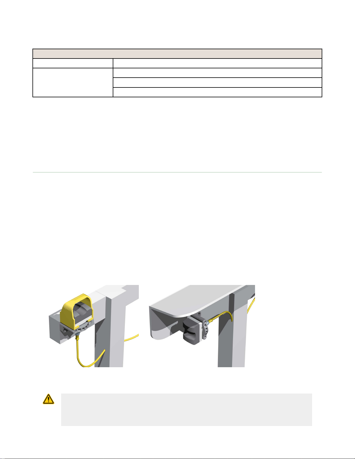
The following figure shows two methods for mounting the touch buttons, to prevent accidental switch actuation. When
mounting them on top of the control bar, the protective field covers should be in place, as shown; or for added protection,
mount the touch buttons sideways under and/or behind a protective hood, rather than on top of the bar, removing the
field covers. This side mount prevents an object from being left in the path of the beam, intentionally bypassing the
safeguard. In addition, shields, covers, rings, collars, dividers, or similar protection may be used to prevent accidental
switch actuation.
Figure 2. Protect STB touch buttons to prevent defeat or inadvertent actuation
CAUTION: Install Hand Controls to Prevent Accidental Actuation
Total protection for the two-hand control system from defeat is not possible. However, the user is
required by U.S. and International standards to arrange and protect hand controls to
minimize the possibility of defeat or accidental actuation.
P/N 64136 Rev. C www.bannerengineering.com - tel: 763-544-3164 3
Page 4
STB Self-Checking Optical Touch Buttons
CAUTION: Hand Controls
The environment in which hand controls are installed must not adversely affect the means of
actuation. Severe contamination or other environmental influences may cause slow response or false
On conditions of mechanical or ergonomic buttons. This may result in exposure to a hazard.
Two-Hand Control Safety Distance (Minimum Distance)
Both hand controls must be located far enough away from the nearest hazard point that the operator cannot reach the
hazard with a hand or other body part before the hazardous motion ceases. This is the “separation distance” (“safety
distance”), and may be calculated as follows.
WARNING: Location of Touch Button Controls
Hand controls must be mounted a safe distance from moving machine parts, as determined
by the appropriate standard. It must not be possible for the operator or other non-qualified persons
to relocate them. Failure to establish and maintain the required safety distance may result in
serious injury or death.
U.S. Applications
The Safety Distance formula, as provided in ANSI B11.19:
Part-Revolution Clutch Machinery (the machine and its controls allow the machine to stop motion during the
hazardous portion of the machine cycle)
Ds = K x (Ts + Tr + Th)
For Full-Revolution Clutch Machinery (the machine and its controls are designed to complete a full machine cycle)
Ds = K x (Tm + Tr + Th)
4 www.bannerengineering.com - tel: 763-544-3164 P/N 64136 Rev. C
Page 5

STB Self-Checking Optical Touch Buttons
U.S. Applications
D
s
the Safety Distance (in inches)
K
the OSHA/ANSI recommended hand-speed constant (in inches per second), in most cases is calculated at 63
in/sec, but may vary between 63 to 100 in/sec based on the application circumstances
not a conclusive determination; consider all factors, including the physical ability of the operator, when
determining the value of K to be used
T
h
the response time of the slowest hand control from the time when a hand disengages that control until the
switch opens
Th is usually insignificant for purely mechanical switches. However, Th should be considered for safety distance
calculation when using electronic or electromechanical (powered) hand controls. For Banner Self-checking
Touch Buttons (STBs) the response time is 0.02 seconds
T
m
the maximum time (in seconds) the machine takes to cease all motion after it has been tripped. For full
revolution clutch presses with only one engaging point, Tm is equal to the time necessary for one and one-half
revolutions of the crankshaft. For full revolution clutch presses with more than one engaging point, Tm is be
calculated as follows:
Tm = (1/2 + 1/N) x T
cy
N = number of clutch engaging points per revolution
Tcy = time (in seconds) necessary to complete one revolution of the crankshaft
T
r
the response time of the Safety Controller as measured from the time a stop signal from either hand control.
The default Safety Controller response is 0.0xx seconds, plus any additional closed-to-open debounce time. If
the debounce time is adjusted, the time in excess of xx ms (default closed-to-open debounce time) must be
added to the stated response (see Specifications).
T
s
the overall stop time of the machine (in seconds) from the initial stop signal to the final ceasing of all motion,
including stop times of all relevant control elements and measured at maximum machine velocity
Ts is usually measured by a stop-time measuring device. If the specified machine stop time is used, add at
least 20% as a safety factor to account for brake system deterioration. If the stop-time of the two redundant
machine control elements is unequal, the slower of the two times must be used for calculating the separation
distance
European Applications
The Minimum Distance Formula, as provided in ISO 13855:
S = (K x T) + C
S
the Minimum Distance (in millimeters)
K
the ISO 13855 recommended hand-speed constant (in millimeters per second), in most cases is calculated at
1600 mm/sec, but may vary between 1600 to 2500 mm/sec based on the application circumstances
not a conclusive determination; consider all factors, including the physical ability of the operator, when
determining the value of K to be used.
T
the overall machine stopping response time (in seconds), from the physical initiation of the safety device to the
final ceasing of all motion
C
the added distance due to the depth penetration factor equals 250 mm, per ISO 13855. The ISO 13855 C
factor may be reduced to 0 if the risk of encroachment is eliminated, but the safety distance must always be
100 mm or greater
Example Separation Distance Calculation
The following example illustrates the use of the formula to calculate separation distance for a part-revolution clutch
machine. This example uses 0.50 seconds as a typical value for Ts and 0.035 seconds for Tr and 0.020 seconds for Th:
P/N 64136 Rev. C www.bannerengineering.com - tel: 763-544-3164 5
Page 6

1
3
2
5
4
Supply Voltage*
(see Specifications)
N.C.
C
N.O.
* NOTE: Connection of dc power is without regard to polarity.
3
1
4
2
10-30V dc
–
+
Load
Load
A
1
K
1
K
2
Inputs Inputs
MPCE
Feedback
A
2
A
1
A
2
A
1
A
2
Machine
Control
Circuit
Two-Hand Control
Type IIIC
MPCE 1MPCE
2
STB Self-Checking Optical Touch Buttons
K = 63" per second,
Ts = 0.50 seconds (measured by a stop-time measuring device)
Tr = 0.035 seconds
Th = 0.020 seconds
Ds = K × (Ts + Tr + Th)
= 63" (0.50 + 0.035 + 0.020)
= 35"
In this example, both hand controls must be located no closer than 35" from the nearest hazard point.
Hookup Diagrams
Cabled models only are shown. Quick-disconnect wiring is functionally identical. Connection of dc power is without regard
to polarity.
Electromechanical Relay Output Models
PNP (Sourcing) Solid-State Output Models Wiring Key
1 = Brown
2 = White
3 = Blue
4 = Black
5 = Gray or Yellow
Wiring Key
1 = Two-Hand Control Type IIIC
Module
2 = Inputs
3 = MPCE feedback
4 = Machine control circuit
Figure 3. Generic interface of a relay-output STB Touch Button to a type IIIC two-hand-control
6 www.bannerengineering.com - tel: 763-544-3164 P/N 64136 Rev. C
module
Page 7

Solid-State
10-30V dc
V+ V+
bn
bl
bn
bl
yl
wh
bu
wh
bu
Micro-
Controller
1
Relay
20-30V ac/dc
V+ V+
Micro-
Controller
2
Micro-
Controller
1
Micro-
Controller
2
K
1
K1K
2
K
2
A
1
+ –
A
2
STB Self-Checking Optical Touch Buttons
WARNING:
Safety Systems Used for Two-Hand-Control. In a two-hand-control/trip system that incorporates STB
Touch Buttons as the actuation devices and functions as a safeguard, the anti-tiedown and simultaneity
monitoring functions should not be performed by a nonsafety-related device (e.g., a PLC or PC). Per
OSHA 29CFR1910.211(d)(62), the “safety system must...operate together as a unit, such that a single
failure or single operating error will not cause injury to personnel due to point-of-operation hazards.”
Refer to the appropriate standard to determine the requirements of a two hand-control/trip system
when used for safeguarding.
Figure 4. STB Touch Button block diagrams
Repairs
Contact Banner Engineering for troubleshooting of this device. Do not attempt any repairs to this Banner device; it
contains no field-replaceable components. If the device or a device component is determined to be defective by a
Banner Applications Engineer, they will advise you of Banner's RMA (Return Merchandise Authorization) procedure.
Important: If instructed to return the device, pack it with care. Damage that occurs in return shipping
is not covered by warranty.
Specifications
Supply Voltage and Current
STBVP6 models: 10 to 30 V dc @ 75 mA, typical
STBVR81 models: 20 to 30 V ac/dc or 20 to 30 V ac (peak-to-peak value), (50/60 Hz ±5%) @ 75 mA
Supply Protection Circuitry
Protected against reverse polarity and transient voltages
Output Configuration
STBVP6 models: Complementary PNP (sourcing) open-collector transistors
STBVR81 models: Complementary electromechanical relays
P/N 64136 Rev. C www.bannerengineering.com - tel: 763-544-3164 7
Page 8

STB Self-Checking Optical Touch Buttons
Output Rating
STBVP6 models (solid-state outputs):
Max. load: 150 mA
On-state max. output voltage (no load): +V(supply) − 1.5 V
Off-state leakage current: < 1 μA
STBVR81 models (electromechanical relays):
Max. switching voltage: 125 V dc/150 V ac
Max. switching current: 1 A @ 24 V dc; 0.4 A @ 125 V ac (resistive loads)
Max. resistive power: 24 W dc/50 VA ac
Mechanical life of relays: 10^9 cycles
Electrical life of relays: 1.5 x 10^5 cycles at 1 amp, 24 V resistive
Output Protection Circuitry
All models protected against false pulse on power-up. Models with solid-state outputs have overload and shortcircuit protection.
Output Response Time
20 milliseconds ON/OFF
Indicators
2 green LED indicators:
Power: ON – power applied
Output/fault: ON – button is activated; OFF – button is deactivated; Flashing – internal fault or blocked button
on power-up detected
Connections
PVC-jacketed 2 m (6.5') cables or QD fitting, depending on model; integral 9 m (30') cables are also available.
Accessory QD cables required for QD models.
STBVP6 models: 4-wire (4-pin Mini-style or Euro-style QD)
STBVR81 models: 5-wire (5-pin Mini-style or Euro-style QD)
Environmental Rating
Meets NEMA standards 1, 3, 4, 4X, 12 and 13; IEC IP66
Construction
Totally encapsulated, non-metallic enclosure. Black polyetherimide upper housing; fiber-reinforced PBT polyester
base. Electronics fully epoxy-encapsulated. Supplied with polypropylene (TP) field cover.
Ambient Light Immunity
Up to 100,000 lux
Applicable Agency Standards
(Used with an AT-FM-10K module or an SC22-3 Safety Controller) Analysis of measures for fault avoidance and
fault control according to SIL3 (IEC 61508 and IEC 62061) and Category 4 (EN ISO 13849-1) passes EMI/RFI test
levels as speCified in IEC61496 and IEC62061..
Operating Conditions
0 to 50 °C (32 to 122 °F)
90% @ 55 ºC max. relative humidity (non-condensing)
Application Notes
The polyetherimide upper housing will become brittle with prolonged exposure to outdoor sunlight. Window glass
effectively filters longer wavelength ultraviolet light and provides excellent protection from sunlight. Avoid contact
with strong alkalis, hydrocarbons and fuels. Clean periodically using mild soap solution and a soft cloth.
Two-Hand Control System Note
When the STBVP6 is used with Banner’s SC22-3 Safety Controller in a two-hand control system, the power supply
to the STBVP6 must be of the same voltage that is used to power the Safety Controller and they must have a
common supply ground.
Certifications
8 www.bannerengineering.com - tel: 763-544-3164 P/N 64136 Rev. C
Page 9

OUTPUT
FAULT
POWER
OUTPUT
FAULT
POWER
OUTPUT
FAULT
POWER
59.9 mm
(2.36")
27.9 mm
(1.10")
43.2 mm
(1.70")
35.0 mm
(1.38")
22.1 mm
(0.87")
22.1 mm
(0.87")
13.0 mm
(0.50")
15.2 mm
(0.60")
22.1 mm
(0.87")
M30 External Threads
Jam Nut, Lock Ring, and
Seal Washers are Supplied
Integral Cable
Mini-Style
Quick-Disconnect
Euro-Style
Quick-Disconnect
With
Field Cover
NPSM Internal Threads
69 mm
(2.7")
74.0 mm
(2.9")
51.0 mm
(2.0")
7/8-16UN-2B
ø 28 mm max.
(1.1")
61 mm max.
(2.4")
4
3
1
2
7/8-16UN-2B
ø 28 mm max.
(1.1")
61 mm max.
(2.4")
1
2
4
3
5
STB Self-Checking Optical Touch Buttons
Dimensions
Accessories
4-Pin Mini-Style Cordsets
Model Length Style Dimensions Pinout
MBCC-406 1.83 m (6 ft) Straight
MBCC-412 3.66 m (12 ft)
MBCC-430 9.14 m (30 ft)
5-Pin Mini-Style Cordsets
Model Length Style Dimensions Pinout
MBCC-506 1.83 m (6 ft)
MBCC-515 4.57 m (15 ft)
MBCC-530 9.14 m (30 ft)
P/N 64136 Rev. C www.bannerengineering.com - tel: 763-544-3164 9
Straight
1 = Brown
2 = White
3 = Blue
4 = Black
1 = Black
2 = Blue
3 = Yellow
4 = Brown
5 = White
Page 10

44 Typ.
ø 14.5
M12 x 1
2
3
4
1
44 Typ.
ø 14.5
M12 x 1
2
3
4
1
5
70
57
A
B
C
57
67
58
29
B
A
45
93
A
C
B
53
48
45
A
C
B
STB Self-Checking Optical Touch Buttons
4-Pin Threaded M12/Euro-Style Cordsets
Model Length Style Dimensions Pinout
MQDC-406 1.83 m (6 ft)
MQDC-415 4.57 m (15 ft)
MQDC-430 9.14 m (30 ft)
Straight
MQDC-450
15.2 m (50 ft)
1 = Brown
2 = White
3 = Blue
4 = Black
5-Pin Threaded M12/Euro-Style Cordsets (Single Ended)
Model Length Style Dimensions Pinout (Female)
MQDC1-501.5 0.50 m (1.5 ft)
MQDC1-506 1.83 m (6 ft)
MQDC1-515 4.57 m (15 ft)
Straight
1 = Brown
MQDC1-530
9.14 m (30 ft)
2 = White
3 = Blue
4 = Black
5 = Gray
SMB30MM
• 12-ga. stainless steel
bracket with curved
mounting slots for versatile
• Clearance for M6 (¼ in)
• Mounting hole for 30 mm
orientation
hardware
sensor
Hole center spacing: A = 51, A to B = 25.4
Hole size: A = 42.6 x 7, B = ø 6.4, C = ø 30.1
SMBAMS30P
• Flat SMBAMS series bracket
• 30 mm hole for mounting
• Articulation slots for 90°+
• 12-ga. 300 series stainless
sensors
rotation
steel
Hole center spacing: A=26.0, A to B=13.0
Hole size: A=26.8 x 7.0, B=ø 6.5, C=ø 31.0
Mounting Brackets
• Swivel bracket with 30 mm
• Black reinforced
• Stainless steel mounting and
• Right-angle SMBAMS series
• 30 mm hole for mounting
• Articulation slots for 90°+
• 12-ga. (2.6 mm) cold-rolled
SMB30SC
mounting hole for sensor
thermoplastic polyester
swivel locking hardware
included
Hole center spacing: A=ø 50.8
Hole size: A=ø 7.0, B=ø 30.0
SMBAMS30RA
bracket
sensors
rotation
steel
Hole center spacing: A=26.0, A to B=13.0
Hole size: A=26.8 x 7.0, B=ø 6.5, C=ø 31.0
10 www.bannerengineering.com - tel: 763-544-3164 P/N 64136 Rev. C
Page 11

45
61
69
A
B
C
STB Self-Checking Optical Touch Buttons
Mounting Brackets
• Right-angle bracket with
• Clearance for M6 (¼ in)
• Mounting hole for 30 mm
• 12-ga. stainless steel
SMB30A
curved slot for versatile
orientation
hardware
sensor
Hole center spacing: A to B=40
Hole size: A=ø 6.3, B= 27.1 x 6.3, C=ø 30.5
Banner Engineering Corp Limited Warranty
Banner Engineering Corp. warrants its products to be free from defects in material and workmanship for one year following
the date of shipment. Banner Engineering Corp. will repair or replace, free of charge, any product of its manufacture
which, at the time it is returned to the factory, is found to have been defective during the warranty period. This warranty
does not cover damage or liability for misuse, abuse, or the improper application or installation of the Banner product.
THIS LIMITED WARRANTY IS EXCLUSIVE AND IN LIEU OF ALL OTHER WARRANTIES WHETHER EXPRESS OR
IMPLIED (INCLUDING, WITHOUT LIMITATION, ANY WARRANTY OF MERCHANTABILITY OR FITNESS FOR A
PARTICULAR PURPOSE), AND WHETHER ARISING UNDER COURSE OF PERFORMANCE, COURSE OF DEALING OR
TRADE USAGE.
This Warranty is exclusive and limited to repair or, at the discretion of Banner Engineering Corp., replacement. IN NO
EVENT SHALL BANNER ENGINEERING CORP. BE LIABLE TO BUYER OR ANY OTHER PERSON OR ENTITY FOR
ANY EXTRA COSTS, EXPENSES, LOSSES, LOSS OF PROFITS, OR ANY INCIDENTAL, CONSEQUENTIAL OR
SPECIAL DAMAGES RESULTING FROM ANY PRODUCT DEFECT OR FROM THE USE OR INABILITY TO USE THE
PRODUCT, WHETHER ARISING IN CONTRACT OR WARRANTY, STATUTE, TORT, STRICT LIABILITY,
NEGLIGENCE, OR OTHERWISE.
Banner Engineering Corp. reserves the right to change, modify or improve the design of the product without assuming any
obligations or liabilities relating to any product previously manufactured by Banner Engineering Corp.
www.bannerengineering.com - tel: 763-544-3164
 Loading...