

Page 1
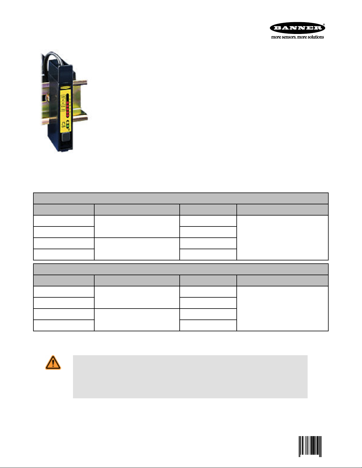
D12 Expert Series - TEACH-Mode Fiber Optic Sensors
0 041974 9
One-button programmable sensors for use with glass or plastic fibers
• Fiber optic sensors for DIN rail mounting; 10 to 30V dc operation
• Visible red (680 nm) light source; models for use with either glass or plastic fibers
• High optical sensing power when needed, also excels at low-contrast sensing
• Easy TEACH-mode programming automatically adjusts sensitivity to optimal setting*
• D12E sensors are designed for low-contrast sensing applications (switching threshold set to just
above the “dark” condition)
• D12E2 sensors set their switching threshold midway between the “dark” and “light” conditions to ignore subtle changes, such as web flutter
• Output may be programmed for either light or dark operate
• Fast 200 microsecond sensing response; programmable 40 millisecond pulse stretcher
• Secure one-button programming is easy to use; one button sets both TEACH and sensor configuration settings
• 7-segment LED bar graph indicates relative received signal strength and sensing contrast, programming status, and diagnostic trouble warnings
• Marginal sensing alarm
• Separate input allows remote programming by an external device, such as a switch or a process controller
* U.S. Patent(s) issued or pending
D12 Expert Series Glass Fiber Optic Models
Models Switching Threshold Setting Output Type Maximum Range
D12EN6FV
D12EP6FV PNP (sourcing)
D12E2N6FV
D12E2P6FV PNP (sourcing)
Models Switching Threshold Setting Output Type Maximum Range
D12EN6FP
D12EP6FP PNP (sourcing)
D12E2N6FP
D12E2P6FP PNP (sourcing)
Standard 2 m (6.5 ft) cable models are listed. To order the 9 m (30 ft) cable model, add suffix "W/30" to the cabled model number
(D12EN6FV W/30).
WARNING: Not To Be Used for Personnel Protection
Never use this device as a sensing device for personnel protection. Doing so could lead to serious
injury or death. This device does not include the self-checking redundant circuitry necessary to allow its
use in personnel safety applications. A sensor failure or malfunction can cause either an energized or deenergized sensor output condition.
Just above the “dark” condition
Midway between “dark” and “light”
conditions
D12 Expert Series Plastic Fiber Optic Models
Just above the “dark” condition
Midway between “dark” and “light”
conditions
NPN (sinking)
NPN (sinking)
NPN (sinking)
NPN (sinking)
Range varies by sensing mode and fiber
optics used; see Glass Fiber - Opposed
Mode on page 9.
Range varies by sensing mode and fiber
optics used; see Plastic Fiber - Opposed
Mode on page 11.
Overview
D12 Expert self-contained sensors offer one-button programming that provides security for your settings, yet is simple to set. D12 Expert
sensors offer two programming modes: TEACH mode and SENSOR OUTPUT CONFIGURATION mode. The D12 Expert also features
P/N 041974 Rev. D 5/2/2013
Page 2

ON
7
6
5
4
3
2
1
ALM
LO
DO
40 ms
0 ms
7-Segment bar graph indicates:
• Signal strength
• Sensing contrast
• Programming status
• Diagnostic display
Output indicator
Power ON indicator
Programming push button
Max. Light Signal
D12E2 Threshold
(Excess gain = 1x)
Light Sensing
Condition
D12E Threshold
(Excess gain = 1x)
Min. Light Signal
Dark Sensing
Condition
D12 Expert Series - TEACH-Mode Fiber Optic Sensors
an advanced and comprehensive LED status display, plus sensor self-diagnostics and an alarm output to signal marginal sensing conditions.
Unlike competitive sensors, D12 Expert models have no exposed switches or adjustments. All programming is accomplished using a single, sealed push button,
using quick commands. Your settings remain secure, and the sensor is sealed
against the elements of the sensing environment. Also, a separate input is provided for remote programming (see Remote Programming on page 7).
Models are available for either glass or plastic fiber optics. Fiber optics are purchased separately to fit your exact sensing application. A few representative fiber
optic styles are listed, see Accessories on page 9 . See Banner's product catalog for the full selection of fiber optic assemblies.
Programming Modes
TEACH Mode
All photoelectric sensing applications (excluding analog response applications) involve differentiating between two received light levels.
The condition with the higher received light level is known as the light condition, and the condition with the lower received light level is
known as the dark condition. The difference between the two conditions is the sensing contrast.
The D12 Expert TEACH mode evaluates the light and dark sensing conditions and automatically adjusts the sensitivity to the optimal
level. Programming is fast, easy, and accurate.
D12 Expert sensors offer high excess gain needed for demanding sensing environments and/or for long-range sensing. However, unlike
standard D12 sensors, D12 Expert sensors also excel in low contrast sensing applications. When a D12 Expert sensor recognizes a lowcontrast application during the TEACH mode process, the sensor’s on-board microprocessor expands the bottom end of the sensitivity
range to establish an accurate setting that allows the sensor to respond to the slight difference in received light levels.
D12E and D12E2 models set their sensing threshold points differently during the
TEACH mode process. D12E sensors automatically place the switching threshold just
above the dark condition taught to the sensor. This scheme works exceptionally well
for sensing a very small sensing contrast, where the light level represented by the
dark condition remains constant. However, in some applications, a subtle rise in the
amount of light received in the dark condition may prevent the D12E from responding
to the intended sensing event.
D12E2 models automatically set the switching threshold at the mid-point between the
light and dark sensing conditions taught to the sensor. This mid-point switching threshold allows D12E2 model sensors to ignore subtle changes in both the light and dark
sensing conditions. D12E2 models were first developed to ignore a small amount of
web flutter in high-speed registration color-mark-sensing applications.
At the end of the TEACH mode process, the D12 Expert bar graph indicator flashes
one to seven segments to indicate the relative sensing contrast (see TEACH-Mode
Programming on page 6), so you know how forgiving your application will be to
changing sensing conditions.
Sensor Output Configuration Mode
The Output Configuration Program mode allows you to set the sensor’s output for either no delay or for a fixed 40 millisecond pulse
stretcher (OFF-delay) for use with loads (or circuit inputs) that are too slow to react to a quick event. With no OFF delay, sensing response is a fast 200 microseconds (.0002 seconds) both ON and OFF.
The output can also be configured for either light operate (LO) or dark operate (DO). Light operate energizes the sensor’s load output
when the light condition is sensed, and dark operate energizes the load output for the dark condition.
The output configuration can be checked at any time by holding down the push button for 2 seconds. The sensor’s 7-segment LED
display indicates the current setting for 10 seconds (see #unique_12/IMAGE_57D2F1371D264F82A6C66190AD29F294 on page 6),
while the sensor continues normal operation. Factory settings for the output configuration are no delay (0 ms) and light operate (LO).
2 www.bannerengineering.com - tel: 763-544-3164 P/N 041974 Rev. D
Page 3
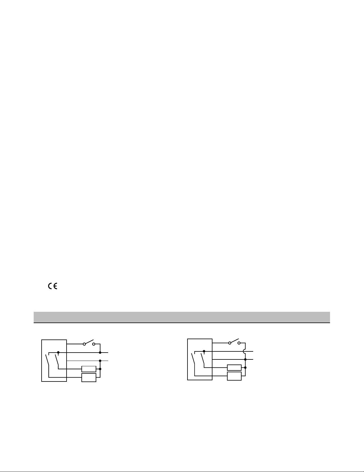
10–30V dc
bn
bu
gy
−
+
bk
wh
Alarm
Load
Remote programming switch
(normally open)
(normally open)
10–30V dc
bu
bn
gy
−
+
bk
wh
Alarm
Load
Remote programming switch
(normally open)
(normally open)
D12 Expert Series - TEACH-Mode Fiber Optic Sensors
Specifications
Supply Voltage and Current
10 to 30V dc at 45 mA max. (exclusive of load); 10%
maximum ripple
Supply Protection Circuitry
Protected against reverse polarity and transient voltages
Adjustments
Push button TEACH mode sensitivity setting; remote
teaching input is provided
Indicators
Green LED lights for DC power ON and flashes when
ready for TEACH mode; 1 Hz when ready to learn first
condition; 2 Hz for second condition
Yellow LED lights for load output ON (conducting)
7-segment Moving Dot Red LED Display indicates rela-
tive received light signal strength, output program settings, relative contrast level and alarm
Construction
Black ABS housing with acrylic cover, stainless steel
M3 x 0.5 hardware for use with PBT polyester mounting bracket (supplied); the plastic fiber clamping element is acetal
Environmental Rating
Rated NEMA 2; IEC IP11
Connections
PVC-jacketed 2 m (6.5 ft) or 9 m (30 ft) cables
Operating Conditions
Temperature: -20 to +70 °C (-5 to +158 °F)
Maximum relative humidity: 90% at 50 °C (non-con-
densing)
Certifications
Output Configuration
NPN open collector (both outputs) or PNP open collector (both outputs), depending on model
Load output: N.O. and programmable light- or dark-operate
Alarm output: N.O.
Output Rating
150 mA maximum each output; the total load may not
exceed 150 mA
Off-state leakage current: less than 10 microamps at
30V dc
On-state saturation voltage: less than 1 volt at 10 mA
dc and less than 1.5 volts at 150 mA dc
Output Protection Circuitry
Protected against false pulse on power-up and overload of outputs (trips at 175 mA)
Output Response Time
200 microseconds ON and OFF (40 milliseconds OFF
when OFF-delay selected)
NOTE: False pulse protection circuit causes a 0.1 second delay on power-up
Output Operation Mode
Light operate or dark operate; selected by push button
Output Timing Functions
ON/OFF (no delay) or fixed 40 millisecond OFF-delay;
selected by push button
Repeatability
66 microseconds
Wiring Diagrams
NPN (Sinking) Outputs PNP (Sourcing) Outputs
P/N 041974 Rev. D www.bannerengineering.com - tel: 763-544-3164 3
Page 4

20.2 mm
(0.79")
35.5 mm
(1.40")
Fiber-retaining Clip
(Supplied with Sensor)
7-Segment Display
Output Indicator
Power Indicator
Push Button
Pull to Relase
Bracket
5.0 mm
(0.20")
Glass Fiber Receiver Port
Glass Fiber Emitter Port
Mounting Bracket
(Included)
12.0 mm
(0.47")
30.0 mm
(1.18")
64.4 mm
(2.52")
20.2 mm
(0.79")
35.5 mm
(1.40")
Fiber Gripper –
Slide up to install or
release fibers
7-Segment display
Output indicator
Power indicator
Push button
Pull to release
bracket
5.0 mm
(0.20")
Plastic fiber receiver port
Plastic fiber emitter port
Mounting bracket
(included)
Small fiber adapter
12.0 mm
(0.47")
30.0 mm
(1.18")
64.4 mm
(2.52")
D12 Expert Series - TEACH-Mode Fiber Optic Sensors
Dimensions
Glass Fiber Optic Models
Glass Fiber Installation.
1. Slide the sensor ends of the fiber(s) into the D12 Expert fiber ports as far as they will go.
2. Push firmly on the fiber ends to compress the o-rings (supplied with the fibers) and to align the grooves in the fiber ends with the
slot above the emitter port. Slide the retaining clip into the slot and press the clip until it snaps into the grooves.
Plastic Fiber Optic Models
Plastic Fiber Installation.
1. Cut fiber ends per instructions included with the fibers. Slide the fiber gripper up (open). (For 0.010 inch or 0.020 inch diameter
2. Insert the prepared plastic fiber sensor ends gently into the ports as far as they will go.
3. Slide the fiber gripper back down to lock.
4 www.bannerengineering.com - tel: 763-544-3164 P/N 041974 Rev. D
fibers, insert the small fiber adaptor into the ports as far as it will go.)
Page 5

Section A-A
A
A
2.5 mm
(0.10")
2.3 mm
(0.09")
24.5 mm
(1.00")
4.8 mm
(0.19")
ø 3.25 mm (2)
(0.128")
8.6 mm
(0.34")
11.9 mm
(0.47")
0.94 mm
(0.037")
3.45 mm (2)
(0.136")
15.2 mm
(0.60")
35.0 mm
(1.38")
9.9 mm
(0.39")
ø 4.45 mm (2)
(0.175")
ø 7.9 mm x 3.0 mm
deep (2)
(0.31" x 0.12")
D12 Expert Series - TEACH-Mode Fiber Optic Sensors
Mounting Bracket
D12E Sensors mount directly to a standard 35mm DIN rail, or may be through-hole mounted using the supplied mounting bracket and
M3 x 0.5 hardware.
Running and Programming the D12 Expert
Run Mode
Normal operation of the D12 Expert is called Run mode. During Run mode, the seven-segment LED display becomes a moving dot
signal strength indicator (see Overview on page 1). When the light and dark sensing conditions are analyzed by the sensor during
TEACH mode, the sensor’s microprocessor automatically distributes the range of signal strength seen in the light condition evenly between the seven LEDs. This display gives a true reading of the relative signal strength for the current application, and is a useful indicator
of changing sensing conditions.
Maximum Sensitivity. D12 Expert sensors are factory set for maximum sensitivity. Use the following TEACH mode procedure at any
time to return the sensitivity to its maximum setting.
Following the TEACH mode procedure (see TEACH-Mode Programming on page 6), teach the following two conditions:
1. No light reaching the receiver. One easy way to do this is to disconnect the emitter and/or receiver fiber at the sensor.
2. Maximum light reaching the receiver. The best way to do this is to pipe the light from the sensor’s emitter port directly into the
receiver port, using a short individual fiber. If this is not convenient, return the greatest amount of light possible to the receiver by
using a reflective target at close range (diffuse mode sensing) or by bringing the sensing end tips together (opposed mode sensing).
Factory Default Settings. D12E and D12E2 sensors are factory set at the following defaults: maximum sensitivity, light operate output
and pulse stretcher OFF. Perform the procedures on the following pages to program your own settings. Unlike competitive sensors, the
D12E has no exposed switches or adjustments.
P/N 041974 Rev. D www.bannerengineering.com - tel: 763-544-3164 5
Page 6

ON
7
6
5
4
3
2
1
ALM
LO
DO
40 ms
0 ms
Light/Dark
Operate Indicators
0 or 40 ms Pulse
Stretcher Indicators
D12 Expert Series - TEACH-Mode Fiber Optic Sensors
Output Configuration Programming
D12 Expert setting indicators, shown set
to factory defaults
Use the push button and a combination of single-, double-, and triple-clicks to program the
sensor. (For a description of these clicks, see Remote Programming on page 7). Two
output functions may be programmed by the push button:
1. Either no delay or a fixed 40 millisecond pulse stretcher (OFF-delay) for loads (or circuit inputs) that are too slow to react to a quick event. With no OFF-delay, sensing
response is a fast 200 microseconds (.0002 seconds), both ON and OFF.
2. The output may be programmed for either light operate (LO) or dark operate (DO). In
light operate, the sensor load output is energized during the light condition; in dark
operate the load output is energized during the dark condition.
These two output functions are programmed in sequence – first the output timing, followed
by the light/dark operate selection – as explained in the chart. The factory settings are 0
millisecond OFF-delay (no delay) and light operate (LO). To check the output configuration
at any time, hold down the push button for 2 seconds. The sensor’s seven-segment LED
display indicates the setting for 10 seconds, while the sensor continues normal operation.
NOTE: To escape from Program mode and return to Run mode at any point, push and hold
the push button for 2 seconds.
Push button
Push and hold 2 seconds or longer - Output settings are displayed.
Triple-click - Output timing selection is displayed.
(Single-click to toggle between 0 ms and 40 ms)
Double-click - Output timing is stored and the LO
or DO selection is displayed.
(Single-click to toggle between LO and DO)
Double-click - LO/DO choice is stored and the
sensor returns to Run mode.
TEACH-Mode Programming
Sensitivity is automatically set (and optimized) by “teaching” the sensor the light and dark conditions in TEACH mode. TEACH mode is
accomplished by presenting each of the two sensing conditions to the fiber optics. They may be presented in either order (the light condition first, then the dark, or vice versa). When the button is clicked, the sensor samples the sensing condition and registers it into memory.
After the second sensing condition is registered, the sensor automatically sets its sensitivity to the optimum value for the application, and
the sensor returns to RUN mode.
NOTE: There is a period of a few seconds at the end of TEACH mode when the display is blank, before RUN mode begins.
Contrast Indication
When the push button is clicked to teach the second condition (see TEACH-Mode Programming on page 6), the 7-segment display flashes 1 to 7 LEDs three times to indicate relative contrast level. Contrast is the difference in light level between the two sensing conditions.
Higher contrast allows a higher sensitivity level, and, therefore, a higher excess gain. In short, a high contrast level is directly related to
sensing reliability, and to the sensor’s ability to “forgive” subtle changes in sensing conditions.
Mode Indicator Status
Change from Run mode to Output Configuration
(Display) mode
Change to Output Configuration (Program)
mode
(Output timing selection)
Continue in Output Configuration (Program)
mode
(Light/dark operate selection)
Return to Run mode The 7-segment LED bar graph indicates relative
Two steady red LEDs indicate the output settings: light or dark operate and output timing (0
or 40 ms).
The sensor continues to operate normally during
the display period. The display automatically returns to Run mode if the button is not pushed
within 10 seconds.
Red LED flashes at 1 Hz opposite either 0 ms or
40 ms output timing. The sensor returns to Run
mode if the button is not pushed within 90 seconds.
(Flashing red LED toggles between 0 ms (no delay) and 40 ms (off-delay))
Red LED flashes at 1 Hz opposite either LO or
DO output mode. The sensor returns to Run
mode if the button is not pushed within 90 seconds.
(Flashing red LED toggles between LO and DO)
received signal strength.
6 www.bannerengineering.com - tel: 763-544-3164 P/N 041974 Rev. D
Page 7

D12 Expert Series - TEACH-Mode Fiber Optic Sensors
Contrast, as indicated by the 7-segment display
LEDs Flash 3 Times at End of TEACH Mode Relative Contrast
1 (only) Unacceptable
1 and 2 Low
1, 2, and 3 Moderate
1, 2, 3, and 4 Good
1, 2, 3, 4, and 5 Very Good
1, 2, 3, 4, 5, and 6 High
1, 2, 3, 4, 5, 6, and 7 Very High
Push Button Mode Indicator Status
Push and hold 2 seconds or longer Current output settings are displayed
Double-click - ON indicator (green
LED) single-flashes at 1 Hz.
TEACH Condition #1 - Present the
first condition to the sensor and single-click the push button
TEACH Condition #2 - Present the
second condition to the sensor and
single-click the push button
Change from Run mode to
Output Configuration (Display)
mode
Change to TEACH mode Green ON LED single-flashes at 1Hz and the 7-segment display indicates
Two steady red LEDs indicate the output settings: light or dark operate and
output timing (0 or 40ms).
The sensor continues to operate normally during the display period. The display automatically returns to Run mode if the button is not pushed within 10
seconds.
relative received signal strength.
There is no timeout for the TEACH mode sequence. To escape from TEACH
mode and return to Run mode with the previous setting, press and hold the
button for 2 seconds or longer.
When the push button is single-clicked, the 7-segment display turns each of
its LEDs ON in sequence from #7 to #1, as the sensor samples and registers
the first condition. The green ON LED double-flashes at 1 Hz to indicate the
sensor is ready to learn the second condition.
There is no timeout for the TEACH mode sequence. To escape from TEACH
mode and return to Run mode with the previous setting, press and hold the
button for 2 seconds or longer.
When the push button is clicked, the 7-segment display will turn each of its
LEDs ON in sequence from #7 to #1, as the sensor samples and registers
the second condition. The 7-segment display will then flash 1 to 7 of its LEDs
three times to indicate relative sensing contrast. (See Figure 4, above right.)
If the contrast is acceptable, the sensor returns (after a few seconds) to RUN
mode with the new, optimized sensitivity setting. If the contrast is unacceptable (indicated by only #1 LED of the 7-segment display flashing three times),
the sensor returns to TEACH mode condition 1.
If the contrast is unacceptable, the ALARM output also pulses three times.
Remote Programming
To remotely program the TEACH and Output Configuration modes, connect the sensor’s gray wire to a remote programming switch. (This
input parallels the push button on the sensor, so the push button sequences explained in Output Configuration Programming on page 6
and Contrast Indication on page 6 also apply for a remote switch.)
Connect a remote programming switch between the gray wire and dc common (see Wiring Diagrams on page 3). The switch may be
either a normally open contact, or an open-collector NPN transistor.
The timing diagrams define single-, double-, and triple-click, simulating the D12 Expert’s programming push button. The ON time of each
click must be at least 40 milliseconds. The minimum space between clicks must be at least 40 milliseconds. The total time of two adjacent clicks of a double- or triple-click must be less than 800 milliseconds. Conversely, there must be at least 800 milliseconds between
the start of a single- or double-click and the next input.
P/N 041974 Rev. D www.bannerengineering.com - tel: 763-544-3164 7
Page 8

Single-click
Double-click
Triple-click
Wait 0.8 seconds before next input
T
1
T
2
2
1
T
1
T
1
T = 0.04 sec to 0.8 sec
T > 0.8 sec
T
2
T
2
T
1
T
1
T
1
T
1
T
1
T
1
H
L
H
L
H
L
ON
7
6
5
4
3
2
1
ALM
LO
DO
40 ms
0 ms
Indicator OFF
Indicator ON
Indicator Single-Flashing
ON
7
6
5
4
3
2
1
ALM
LO
DO
40 ms
0 ms
Indicator OFF
Indicator ON
Indicator Single-Flashing
D12 Expert Series - TEACH-Mode Fiber Optic Sensors
Self-Diagnostics
D12 Expert sensors provide several self-diagnostic functions. One or more flashing LEDs on the 7-segment display indicates a trouble
condition and an alarm output warns of marginal sensing conditions.
The D12 Expert’s 7-segment display indicates four problems:
LED Behavior
Flashing LED #7 and solid
green ON indicator
Problem
The sensor flashes the #7 LED continuously and energizes the alarm
output when a marginal sensing condition develops during Run mode.
Check the sensing area for any change affecting the received light
level in either or both sensing conditions (for example, dirt buildup on
the sensing end of a fiber, misalignment of a fiber, or a change in the
target’s physical properties).
If no changes can be identified, re-teach the sensor.
Flashing LED #7 and no
green ON indicator
8 www.bannerengineering.com - tel: 763-544-3164 P/N 041974 Rev. D
Load output is overloaded. Remove power, correct the problem, and
re-apply power. Sensor will come up in Run mode with the most recent settings.
Page 9

ON
7
6
5
4
3
2
1
ALM
LO
DO
40 ms
0 ms
Indicator OFF
Indicator ON
Indicator Single-Flash 6 Times
ON
7
6
5
4
3
2
1
ALM
LO
DO
40 ms
0 ms
Indicator OFF
Indicator ON
Indicator Single-Flashing
Bundle
Diameter
.18
.043
.50.50 1.0 ± .030
.29
Bundle
Diameter
.18
.060
.50.50 1.0 ± .030
.29
Bundle
Diameter
5/16 x 24 Thd Brass
2 Jam Nuts included
.50.31 1.5
D12 Expert Series - TEACH-Mode Fiber Optic Sensors
LED Behavior Problem
LEDs #1 and 7 flash together 6 times
This occurs at the end of TEACH mode when the sensor has received
faulty data. Faulty data may result from an unstable target or from
high electrical noise occurring while TEACH mode is in process. The
sensor returns to Run mode, with the previous setting. Re-teach the
sensor.
LEDs #2 and 7 flash together
These LEDs flash continuously to indicate a sensor component failure. Return the sensor to the factory for replacement.
Accessories
The following table lists all the fiber sizes that can be used with these sensors. Typical fiber models (one for each size and type) are
indicated, along with the maximum range for each (expect less range for fiber assemblies with angled sensing ends). For a complete
selection of fibers in these sizes and for more information see your current Banner Engineering Catalog.
Range data is for 0.9 m (3 ft) glass fiber assemblies.
Glass Fiber - Opposed Mode
IMM.443S Features Sensors Range
• Fiber diameter: 0.7 mm (0.027 inches)
• Individual fiber
• Stainless steel flexible conduit
D12E 107 mm (4.2 inches)
• Used in pairs, but sold individually; two are
required
IM.753S Features Sensors Range
• Fiber diameter: 1.2 mm (0.046")
• Individual fiber
• Stainless steel flexible conduit
D12E 295 mm (11.6 inches)
• Used in pairs, but sold individually; two are
required
IT13S Features Sensors Range
P/N 041974 Rev. D www.bannerengineering.com - tel: 763-544-3164 9
• Fiber diameter: 1.6 mm (0.062")
• Individual fiber
• Thread
• Stainless steel flexible conduit
D12E 442 mm (17.4 inches)
Page 10

Bundle
Diameter
5/16 x 24 Thd Brass
2 Jam Nuts included
.50.31 1.5
Bundle
Diameter
.18
.043
.50.50 1.0 ± .030
.29
Bundle
Diameter
.18
.060
.50.50 1.0 ± .030
.29
Bundle
Diameter
5/16 x 24 Thd Brass
2 Jam Nuts included
.50.31 1.5
Bundle
Diameter
5/16 x 24 Thd Brass
2 Jam Nuts included
.50.31 1.5
D12 Expert Series - TEACH-Mode Fiber Optic Sensors
IT13S Features Sensors Range
• Used in pairs, but sold individually; two are
required
IT23S Features Sensors Range
• Fiber diameter: 3.18 mm
• Individual fiber
• 19 mm bend radius
• Thread
• Stainless steel flexible conduit
• Lenses available
• Used in pairs, but sold individually; two are
required
D12E 930 mm
D12 550 mm
QS18 900 mm
R55F 1050 mm
SME312 250 mm
Glass Fiber - Diffuse Mode
Based on a 90% reflectance white test card.
BMM.443P Features Sensors Range
• Fiber diameter: 0.7 mm (0.027 inches)
• Bifurcated fiber
• PVC with galvanized monocoil reinforcing
D12E 55 mm (0.6 inches)
wire sheathing
BM.753S Features Sensors Range
• Fiber diameter: 1.2 mm (0.046")
• Bifurcated fiber
D12E 46 mm (1.8 inches)
• Stainless steel flexible conduit
BT13S Features Sensors Range
• Fiber diameter: 1.6 mm (0.062")
• Bifurcated fiber
• Thread
D12E 68 mm (2.7 inches)
• Stainless steel flexible conduit
BT23S Features Sensors Range
D12E 178 mm
• Fiber diameter: 3.18 mm
• Bifurcated fiber
• 19 mm bend radius
• Thread
• Stainless steel flexible conduit
D12 150 mm
QS18 100 mm
R55F 110 mm
SME312 25 mm
10 www.bannerengineering.com - tel: 763-544-3164 P/N 041974 Rev. D
Page 11

M2.5 x 0.45
10.0 mm
ø 0.25 mm
polyethylene
(.39”)
(.010”)
stainless steel
M3 x 0.5
11.0 mm ø 0.5 mm
polyethylene
(.43”)
(.02”)
nickel plated brass
polyethylene
M4 x 0.7
3.0 mm
Fiber
M2.5 x 0.45
(.12”) Diameter
nickel plated brass
11.0 mm
(.43”)
polyethylene
M4 x 0.7
3.0 mm
Fiber
M2.5 x 0.45
(.12”) Diameter
nickel plated brass
11.0 mm
(.43”)
2X ø 0.25 mm
polyethylene
M3 x 0.5
11.0 mm
(.43”)
(.010”)
stainless steel
D12 Expert Series - TEACH-Mode Fiber Optic Sensors
Plastic Fiber - Opposed Mode
PIT16U Features Sensors Range
DF-G1 58 mm
• Fiber diameter: 0.25 mm
• Individual fiber pair
• 8 mm bend radius
• Thread
D10D 90 mm
D10B 20 mm
D10A 15 mm
D12E 18 mm
PIT26U Features Sensors Range
DF-G1 220 mm
• Fiber diameter: 0.5 mm
• Individual fiber pair
• 12 mm bend radius
• Thread
D10D 400 mm
D10B 95 mm
D10A 75 mm
D12E 84 mm
PIT46U Features Sensors Range
DF-G1 820 mm
• Fiber diameter: 1.0 mm
• Individual fiber pair
• 25 mm bend radius
• Thread
D10D 1200 mm
D10B 320 mm
D10A 300 mm
D12E 315 mm
PIT66U Features Sensors Range
DF-G1 1320 mm
• Fiber diameter: 1.5 mm
• Individual fiber pair
• 38 mm bend radius
• Thread
• Long range
D10D 2400 mm
D10B 600 mm
D10A 525 mm
D12E 660 mm
Plastic Fiber - Diffuse Mode
Based on a 90% reflectance white test card.
PBT16U Features Sensors Range
DF-G1 12 mm
• Fiber diameter: 0.25 mm
• Bifurcated fiber
• 8 mm bend radius
• Thread
D10D 30 mm
D10B 7 mm
D10A 5 mm
D12E 3.8 mm
P/N 041974 Rev. D www.bannerengineering.com - tel: 763-544-3164 11
Page 12

2X ø 0.5 mm
polyethylene
M3 x 0.5
11.0 mm
(.43”) (.02”)
nickel plated brass
14.0 mm
M6 x 0.75
ø 4.0 mm
3.0 mm
(.16”)
(.12”)
(.55”)
polyethylene
nickel plated brass
Fiber
Diameter
14.0 mm
M6 x 0.75
ø 4.0 mm
3.0 mm
(.16”)
(.12”)
(.55”)
polyethylene
nickel plated brass
Fiber
Diameter
D12 Expert Series - TEACH-Mode Fiber Optic Sensors
PBT26U Features Sensors Range
DF-G1 80 mm
• Fiber diameter: 0.5 mm
• Bifurcated fiber
• 12 mm bend radius
• Thread
D10D 150 mm
D10B 38 mm
D10A 25 mm
D12E 25 mm
PBT46U Features Sensors Range
DF-G1 220 mm
• Fiber diameter: 1.0 mm
• Bifurcated fiber
• 25 mm bend radius
• Thread
D10D 300 mm
D10B 100 mm
D10A 85 mm
D12E 95 mm
PBT66U Features Sensors Range
DF-G1 310 mm
• Fiber diameter: 1.5 mm
• Bifurcated fiber
• 38 mm bend radius
• Thread
• Long range
D10D 475 mm
D10B 200 mm
D10A 170 mm
D12E 190 mm
Banner Engineering Corp Limited Warranty
Banner Engineering Corp. warrants its products to be free from defects in material and workmanship for one year following the date of
shipment. Banner Engineering Corp. will repair or replace, free of charge, any product of its manufacture which, at the time it is returned
to the factory, is found to have been defective during the warranty period. This warranty does not cover damage or liability for misuse,
abuse, or the improper application or installation of the Banner product.
THIS LIMITED WARRANTY IS EXCLUSIVE AND IN LIEU OF ALL OTHER WARRANTIES WHETHER EXPRESS OR IMPLIED (INCLUDING, WITHOUT LIMITATION, ANY WARRANTY OF MERCHANTABILITY OR FITNESS FOR A PARTICULAR PURPOSE), AND
WHETHER ARISING UNDER COURSE OF PERFORMANCE, COURSE OF DEALING OR TRADE USAGE.
This Warranty is exclusive and limited to repair or, at the discretion of Banner Engineering Corp., replacement. IN NO EVENT SHALL
BANNER ENGINEERING CORP. BE LIABLE TO BUYER OR ANY OTHER PERSON OR ENTITY FOR ANY EXTRA COSTS, EXPENSES, LOSSES, LOSS OF PROFITS, OR ANY INCIDENTAL, CONSEQUENTIAL OR SPECIAL DAMAGES RESULTING FROM ANY
PRODUCT DEFECT OR FROM THE USE OR INABILITY TO USE THE PRODUCT, WHETHER ARISING IN CONTRACT OR WARRANTY, STATUTE, TORT, STRICT LIABILITY, NEGLIGENCE, OR OTHERWISE.
Banner Engineering Corp. reserves the right to change, modify or improve the design of the product without assuming any obligations or
liabilities relating to any product previously manufactured by Banner Engineering Corp.
www.bannerengineering.com - tel: 763-544-3164
 Loading...