

Page 1
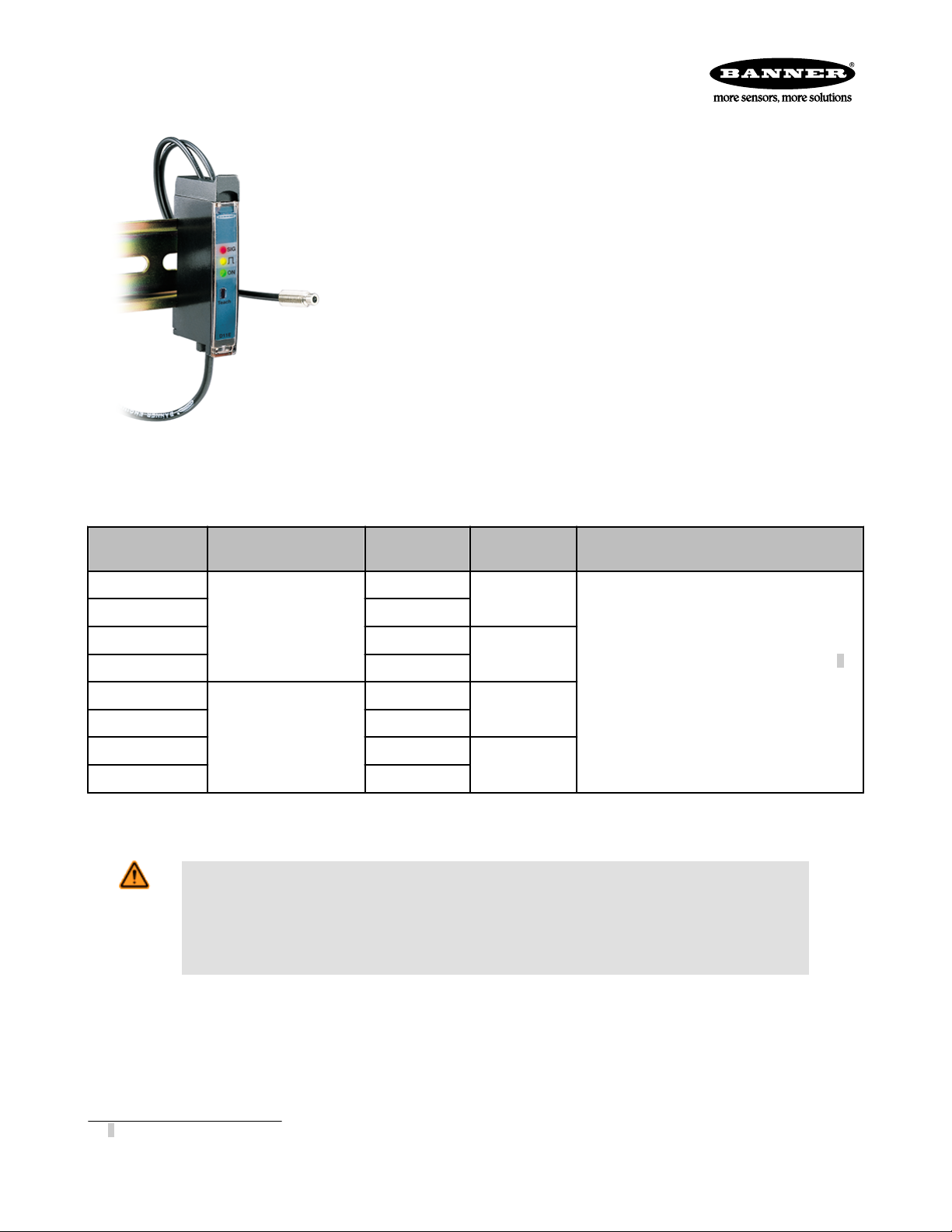
D11 Expert Series
Low-cost TEACH-mode sensors for use with plastic fiber optics
• Low-cost, 10 to 30V dc, self-contained, TEACH-mode sensors for use with all Banner
plastic fiber optics
• Compact 11 mm-wide housing designed for DIN rail mounting; also mounts to other
surfaces using the supplied mounting bracket
• Easy push-button TEACH-mode programming automatically adjusts sensitivity to optimal setting
• D11E sensors are designed for low-contrast sensing applications (sensitivity set to just
above the “dark” condition)
• D11E2 series sensors set the switching point midway between the “dark” and “light”
conditions to ignore subtle changes, such as web flutter
• Fast, 200 microsecond (0.2 millisecond) output response; a 40 millisecond output pulse
stretcher also may be programmed
• Models available with NPN (sinking) or PNP (sourcing) output
• Output may be programmed for either light operate (“LO”) or dark operate (“DO”)
• Separate input allows remote programming by an external device, such as a switch or
Models available with integral 2 m (6.5 ft)
cable or Pico-style quick-disconnect (QD)
connector; 9 m (30 ft) cables are also
available
a process controller
• LED status indications for power ON, output state, received signal strength, and sensing contrast
Models
D11EN6FP
D11EN6FPQ 4-pin Pico QD
D11EP6FP 2 m (6.5 ft)
D11EP6FPQ 4-pin Pico QD
D11E2N6FP
D11E2N6FPQ 4-pin Pico QD
D11E2P6FP 2 m (6.5 ft)
D11E2P6FPQ 4-pin Pico QD
Switching Threshold Setting
Just above the “dark” condition
Midway between “dark” and
“light” conditions
Cable Output Type
2 m (6.5 ft)
2 m (6.5 ft)
NPN (sinking)
PNP (sourcing)
NPN (sinking)
PNP (sourcing)
Maximum Range (Diffuse mode performance
based on 90% reflectance white test card)
Range varies by sensing mode and fiber optics used:
• PIT46U fibers, opposed mode: 180 mm (7.1")
• PIT26U fibers, opposed mode: 50 mm (2.0")
• PBT46U fiber, diffuse mode: 50 mm (2.0")
• PBT26U fiber, diffuse mode: 10 mm (0.4")
Standard 2 m (6.5 ft) cable models are listed. To order the 9 m (30 ft) cable model, add suffix "W/30" to the cabled model number. For
example, D11EN6FP W/30. Models with a QD connector require a mating cable. (See Accessories).
WARNING: Not To Be Used for Personnel Protection
Never use this device as a sensing device for personnel protection. Doing so could lead to serious
injury or death. This device does not include the self-checking redundant circuitry necessary to allow its
use in personnel safety applications. A sensor failure or malfunction can cause either an energized or deenergized sensor output condition.
1
Specifications
Supply Voltage and Current
10 to 30V dc (10% maximum ripple) at less than 45
mA, exclusive of load
1
Opposed-mode range may be extended using optional lenses (see catalog for available lenses).
P/N 44279 Rev. C 8/6/2013
Required Fiber Optic Cable
PI or PB Series plastic fibers
Page 2
1
2
3
4
D11 Expert Series
Supply Protection Circuitry
Protected against reverse polarity and transient voltages
Output Configuration
One (SPST) NPN (sinking) or PNP (sourcing) opencollector transistor, depending on model; programmable for light or dark operate
Output Rating
150 mA maximum
Off-state leakage current: <5 microamps at 30V dc
On-state saturation voltage: <1V at 10 mA dc; <1.5V at
150 mA dc
Output Protection Circuitry
Protected against false pulse on power-up and continuous overload or short-circuit
Output Response Time
200 microseconds (0.2 milliseconds) ON and OFF (40
milliseconds OFF when pulse stretcher is programmed). NOTE: 100 millisecond delay on power-up; output is non-conducting during this time
Output Timing Functions
ON/OFF (no delay) or fixed 40 millisecond OFF-delay
pulse stretcher; selected by push button
Operating Temperature
–10 to +55 ºC (–14 to +131 ºF)
Maximum relative humidity 90% at 50ºC (non-condens-
ing)
Certifications
Sensing Beam
Visible red, 680 nm
Repeatability
66 microseconds
Adjustments
Push button TEACH mode sensitivity setting (see
TEACH mode, page 2); remote TEACH mode input is
provided
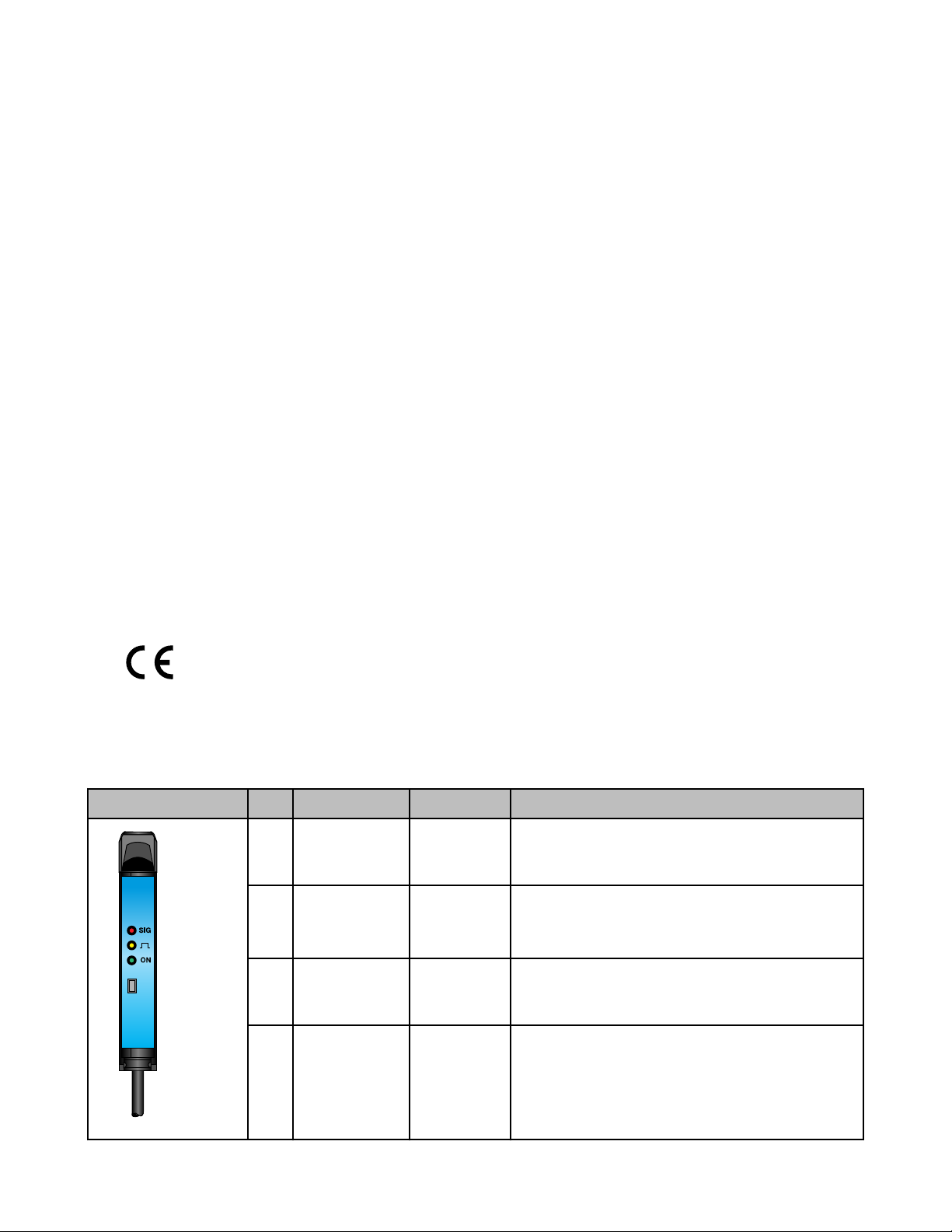
Indicators
Three LEDs: Green, Yellow and Red
Green LED lights for dc power ON and flashes when
ready to register sensing condition during TEACH
mode: 1 Hz when waiting to learn first sensing condition; 2 Hz when waiting to learn second sensing condition; 4 Hz when output is overloaded.
Yellow LED lights for output ON (conducting).
Red LED is Banner’s patented Alignment Indicating
Device (AID™, U.S. patent #4356393) which lights
whenever the sensor “sees” a light condition and superimposes a pulse rate which is proportional to the
strength of the received light signal (the stronger the
signal, the faster the pulse rate).
Construction
Black ABS flame retardant housing with acrylic cover
Stainless steel M3 x 0.5 hardware for use with ABS
mounting bracket (supplied)
Environmental Rating
IEC IP54; NEMA 2
Connections
2 m (6.5 ft) or 9 m (30 ft) attached cable, or 4-pin Picostyle quick-disconnect fitting; Cables for QD models
are purchased separately
Run Mode
Run mode is the normal operation of the D11 Expert series. The LED indicators operate in Run mode, as follows:
Indicator LED Color Function
1 Signal Strength
(SIG)
2 Output Amber Follows the action of the output:
3 Power ON Green Solid when power is applied.
2 www.bannerengineering.com - tel: 763-544-3164 P/N 44279 Rev. C
4 Button n/a Programming push button
Red Lights when the sensor "sees" its modulated light source
and pulses at a rate proportional to the received light signal
strength.
• On when the output is energized
• Off when the output is de-energized
Flashes at approximately 4 Hz to indicate the output is overloaded
Page 3
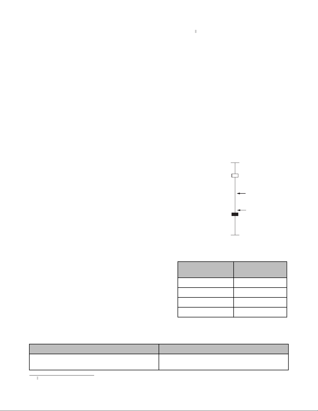
Max. Light Signal
Threshold for
D11E2 (e.g. = 1x)
Light Sensing
Condition
Threshold for
D11E (e.g. = 1x)
Min. Light Signal
Dark Sensing
Condition
D11 Expert Series
2
The Signal Strength indicator is Banner’s exclusive AID™ (Alignment Indicating Device
). This feature simplifies accurate alignment
during TEACH mode and provides a means of signaling when maintenance is needed during Run mode. When the pulse rate is slow,
clean the fiber sensing ends and check the alignment.
Maximum Sensitivity/Factory Defaults
The sensors are factory-programmed for maximum sensitivity. This default setting may be easily recalled by holding the push button for
two or more seconds to enter TEACH mode, and then clicking the push button four times in a row.
The default program also is set for light operate output and pulse stretcher OFF, push button enabled.
Perform the following procedures to program your own settings.
TEACH Mode
Sensitivity is automatically set (and optimized) by “teaching” the sensor the “light” and “dark” conditions. This is accomplished in TEACH
mode. TEACH mode requires that each of the two sensing conditions be presented to the fiber optics; when the push button is clicked,
the sensor samples the sensing condition and registers it into memory. After the second sensing condition is registered, the D11 Expert
automatically sets the sensitivity to the optimum value for the application, and then returns to Run mode.
NOTE: There is a period of a few seconds at the end of TEACH mode, before Run mode begins.
Light or Dark Operate Selection
The two sensing conditions may be presented in either order: the light condition first,
and then the dark condition, or vice versa. The condition presented first is the condition for which the output energizes. (In other words, the output will be light operated if
the light condition is TEACH condition #1, or the output will be dark operated if the
dark condition is TEACH condition #1.)
D11E sensors automatically set to a point just above the “dark” condition for the best
performance in low contrast sensing applications; D11E2 sensors automatically set to
a point midway between the “dark” and “light” conditions, to ignore subtle changes,
such as web flutter.
Contrast Indication
When the push button is clicked to teach the second sensing condition, the
three LED indicators flash simultaneously to indicate relative sensing contrast. (Contrast is the difference in light level between the two sensing conditions.)
Higher contrast allows higher sensitivity level, and resulting higher excess
gain. A high contrast level is directly related to sensing reliability, and is
more forgiving of subtle changes in sensing conditions. The contrast display
at the end of TEACH mode is shown.
No. of flashes at end of
TEACH mode
1 Unacceptable
2 Low
3 Moderate
4 High
Relative Contrast
NOTE: If the relative contrast level is unacceptable (1 flash), the program
will return to TEACH condition #1.
TEACH Mode Programming
Action Indicator Status
Push and hold the button for more than 2 seconds. Green LED: Flashes at 1 Hz
2
U.S. Patent #4356393
P/N 44279 Rev. C www.bannerengineering.com - tel: 763-544-3164 3
Amber LED: Off
Page 4

bn
bu
−
+
bk
wh
Load
10-30V dc
Load
Remote programming
switch (normally open)
bn
bu
−
+
bk
wh
Load
10-30V dc
Load
Remote programming
switch (normally open)
D11 Expert Series
Action Indicator Status
Red LED: Pulses to indicate relative received signal strength
TEACH Condition #1
Present the first sensing condition to the sensor and single-click
the button.
This condition corresponds to the sensor output ON state.
TEACH Condition #2
Present the second sensing condition to the sensor and singleclick the button.
This condition corresponds to the sensor output OFF state.
Output Pulse Stretcher
A 40 millisecond pulse stretcher (OFF-delay) may be enabled for applications where a very short sensing event might be missed because
of the response of the load or input connected to the sensor output. Turn the pulse stretcher ON or OFF using the following procedure.
Action Indicator Status
Push and hold the button for more than 2 seconds. Green LED: Flashes at 1 Hz
Pulse Stretcher
Double-click the button to display status.
Single-click the button to toggle pulse stretcher ON or OFF
3
Green: Flashes at 2 Hz
Yellow: OFF
Red: Pulses to indicate relative received signal strength.
Green, Yellow, and Red indicators flash simultaneously one to four
times to indicate relative sensing contrast (see chart above).
After a few seconds, the sensor returns to RUN mode.
Amber LED: Off
Red LED: Pulses to indicate relative received signal strength
Pulse Stretcher ON
Green: Off
Amber: Off
Red: Solid on
Double-click the button to save the configuration and return to Run
mode.
Hookup Diagrams
Sensors with NPN (Sinking) Outputs Sensors with PNP (Sourcing) Outputs
Figure 1. Cabled Hookup
Pulse Stretcher OFF
Green: Off
Amber: Off
Red: Double-flash
See Run Mode on page 2
Figure 2. Cabled Hookup
3
The sensor returns to RUN mode if the first TEACH condition is not registered within 20 seconds. TEACH mode may be cancelled before either condition #1 or #2 by pressing the push
button for more than 2 seconds.
4 www.bannerengineering.com - tel: 763-544-3164 P/N 44279 Rev. C
Page 5

bn
bu
−
+
bk
wh
Load
10-30V dc
Load
Remote programming
switch (normally open)
bn
bu
−
+
bk
wh
Load
10-30V dc
Load
Remote programming
switch (normally open)
ø 9.0
32 Typ.
4
3
1
2
ø 10.9
29 Typ.
15 Typ.
Programming
Push Button
Power Indicator
Output Indicator
Signal Strength Indicator
ø 1.0 mm (0.04")
Plastic Fiber Emitter Port
ø 1.0 mm (0.04")
Plastic Fiber Receiver Port
Mounting Bracket
(Included)
35.0 mm
(1.38")
17.6 mm
(0.69")
64.1 mm
(2.53")
11.0 mm
(0.43")
29.0 mm
(1.14")
Slide Up
to Release
Fibers
Slide Up
to Release
Fibers
D11 Expert Series
Sensors with NPN (Sinking) Outputs Sensors with PNP (Sourcing) Outputs
Figure 3. Quick Disconnect Hookup
Figure 4. Quick Disconnect Hookup
Accessories
4-Pin Snap-on M8/Pico-Style Cordsets
Model Length Style Dimensions Pinout
PKG4-2 2.00 m (6.56 ft) Straight
PKW4Z-2 2.00 m (6.56 ft) Right-Angle
Dimensions
1 = Brown
2 = White
3 = Blue
4 = Black
Plastic Fiber Installation:
1. Cut fiber ends per instructions included with the fibers. Slide the fiber gripper up (open). For 0.25 mm or 0.5 mm diameter fibers,
insert the adapter (shown below) into the ports as far as it will go.
2. All sizes plastic fibers: Insert the prepared plastic fiber sensor ends gently into the ports as far as they will go.
P/N 44279 Rev. C www.bannerengineering.com - tel: 763-544-3164 5
Figure 5. Cabled Models
Page 6

Programming
Push Button
Power Indicator
Output Indicator
Signal Strength Indicator
ø 1.0 mm (0.04")
Plastic Fiber Emitter Port
ø 1.0 mm (0.04")
Plastic Fiber Receiver Port
Mounting Bracket
(Included)
35.0 mm
(1.38")
17.6 mm
(0.69")
64.1 mm
(2.53")
79.0 mm
(3.11")
11.0 mm
(0.43")
29.0 mm
(1.14")
Slide Up
to Release
Fibers
DIN Rail
35.0 mm
(1.38")
25.1 mm
(0.99")
30.2 mm
(1.19")
5.0 mm
(0.20")
9.9 mm
(0.39")
2 x C’sink
ø 7.9 mm (0.31")
3.2 mm (0.13") deep
ø4.4 (0.18") thru
2 x ø 3.25 mm
(0.128")
2 x 3.5 mm
(0.14")
5.5 mm
(0.22")
11.0 mm
(0.44")
25.6 mm
(1.01")
9.6 mm
(0.38")
2.5 mm
(0.10")
8.6 mm
(0.34")
4.8 mm
(0.19")
2 x ø 3.18 mm
(0.125")
D11 Expert Series
3. Slide the fiber gripper back down to lock.
A fiber adaptor is included for use with 0.25 mm (0.01") or 0.5 mm (0.02") diameter fibers.
Figure 6. Quick Disconnect Models
Figure 7. DIN Rail Mounting
Remote Programming
Connect the D11 Expert's white wire to a remote switch for three sensor programming functions:
1. Disable or enable the push button
2. TEACH mode programming of sensitivity
6 www.bannerengineering.com - tel: 763-544-3164 P/N 44279 Rev. C
Figure 8. Mounting Bracket
Page 7

Single-Pulse
Input
Wait > 0.8 seconds before next input
0.04 sec T < 0.8 sec
T
Two-Pulse
Input
Wait > 0.8 seconds before next input
T
T
T
Four-Pulse
Input
Wait > 0.8 seconds before next input
T
T T T
T T T
D11 Expert Series
3. Enable or disable the 40- millisecond pulse stretcher.
Connect a remote programming switch between the
white wire and dc common (see Hookup Diagrams
on page 4). The switch may be either a normally
open contact, or an open-collector NPN transistor
with its emitter connected to dc common.
Program the sensor using a specified sequence of
input pulses. The duration of each pulse is defined
as: 0.04 seconds < T < 0.8 seconds.
The required spacing between adjacent pulses in a
sequence (e.g., a “double-pulse”) is: 0.04 < T < 0.8
seconds. The timing diagrams illustrate the input
requirements.
Figure 9. Timing Programs
Disable or Enable the Push Button
When remote programming is used exclusively, it may be beneficial to disable the push button on the D11E to increase the security of the
settings.
1. To disable the push button: Pulse the remote input four times.
2. To enable the push button at a later date: Pulse the input four times (again).
NOTE: The push button can be enabled and/or disabled via remote line only.
Set Sensitivity Via TEACH Mode
1. Present the first (output ON) sensing condition to the sensor and pulse the remote input once.
2. Present the second (output OFF) sensing condition to the sensor and pulse the remote input once. The three LED indicators flash
simultaneously one to four times to indicate relative sensing contrast. The sensor returns to RUN mode.
Enable or Disable the 40-millisecond Pulse Stretcher
1. Pulse the remote input two times. The status of the pulse stretcher is indicated by the red LED: ON if the pulse stretcher is ON, and
double-flash if the pulse stretcher is OFF.
2. Pulse the remote input once to toggle the pulse stretcher ON or OFF.
3. Pulse the remote input two times to save the setting and return to Run mode.
Banner Engineering Corp Limited Warranty
Banner Engineering Corp. warrants its products to be free from defects in material and workmanship for one year following the date of
shipment. Banner Engineering Corp. will repair or replace, free of charge, any product of its manufacture which, at the time it is returned
to the factory, is found to have been defective during the warranty period. This warranty does not cover damage or liability for misuse,
abuse, or the improper application or installation of the Banner product.
THIS LIMITED WARRANTY IS EXCLUSIVE AND IN LIEU OF ALL OTHER WARRANTIES WHETHER EXPRESS OR IMPLIED (INCLUDING, WITHOUT LIMITATION, ANY WARRANTY OF MERCHANTABILITY OR FITNESS FOR A PARTICULAR PURPOSE), AND
WHETHER ARISING UNDER COURSE OF PERFORMANCE, COURSE OF DEALING OR TRADE USAGE.
This Warranty is exclusive and limited to repair or, at the discretion of Banner Engineering Corp., replacement. IN NO EVENT SHALL
BANNER ENGINEERING CORP. BE LIABLE TO BUYER OR ANY OTHER PERSON OR ENTITY FOR ANY EXTRA COSTS, EXPENSES, LOSSES, LOSS OF PROFITS, OR ANY INCIDENTAL, CONSEQUENTIAL OR SPECIAL DAMAGES RESULTING FROM ANY
P/N 44279 Rev. C www.bannerengineering.com - tel: 763-544-3164 7
Page 8

D11 Expert Series
PRODUCT DEFECT OR FROM THE USE OR INABILITY TO USE THE PRODUCT, WHETHER ARISING IN CONTRACT OR WARRANTY, STATUTE, TORT, STRICT LIABILITY, NEGLIGENCE, OR OTHERWISE.
Banner Engineering Corp. reserves the right to change, modify or improve the design of the product without assuming any obligations or
liabilities relating to any product previously manufactured by Banner Engineering Corp.
www.bannerengineering.com - tel: 763-544-3164
 Loading...