

Bang Olufsen beovox penta schematic
Beolab
Type 6601, 6602, 6603, 6604, 6605
Penta
Beovox
Type 6611
Penta
BANG
& OLUFSEN
2-1
Bang&Oiufsen
INDHOLD
Diagrammer
Halvlederoversigt . . . . . . . . . . . . . . . . . . . . . . . . . . . . . . .
Elektrisk stykliste . . . . . . . . . . . . . . . . . . . . . . . . . . . . . .
Mekanisk stykliste
Justeringer
Tekniske speci:fikationer
Ad'skillelse
Servicetips . . . . . . . . . . . . . . . . . . . . . . . . . . . . . . . . . . . . . . 2-17
t~
olationstest
....................................
.......................
......................................
........................
...................
. . . . . . . . . . . . . . . . . . . . . . . . . . . . . . . . . . .
.
....
·. . . . . . . . . . . . . . 2-17
.
......
2-1
2-5
2-8
2-11
2-15
2-15
2-21
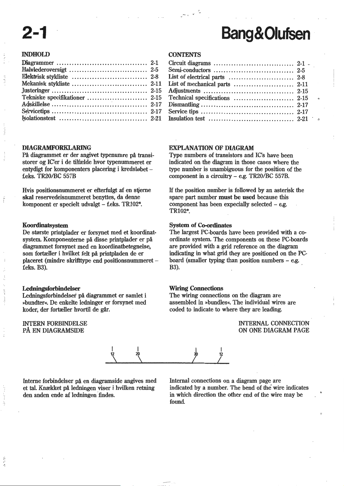
DIAGRAMFORKLARING
Pa diagrammet
storer og
entydigt for komponenters placering i kredslabet ieks. TR20/BC 557B
Hvis positionsnummeret
skal
reservedelsnummeret benyttes, da denne
komponent er specielt
er
der angivet typenumre pa transi-
ICer i de tilfrelde hvor typenummeret
er
efterfulgt af en stjerne
udvalgt-
ieks. TR102*.
er
CONTENTS
Circuit diagrams . . . . . . . . . . . . . . . . . . . . . . . . . . . . . . . .
Semi-conductors . . . . . . . . . . . . . . . . . . . . . . . . . . . . . . . .
List of electrical parts .
List of mechanical parts . .
Adjustments . . . . . . . . . . . . . . . . . . . . . . . . . . . . . . . . . . . .
Technical specifications . . . . . . . . . . . . . . . . . . . . . . . .
Dismantling .
Service tips .
Insulation
..
..
.. . ..
.. .. ..
test
. . . . . . . . . . . . . . . . . . . . . . . . . . . . . . . . . .
EXPLANATION OF
Type numbers of transistors and IC's have been
indicated on the diagram in those cases where the
type number is unambiguous for the position
component in a
If the position nuniber is followed by an asterisk the
spare part number
component has been expecially selected -
TR102*.
circuitry-
.. .. ..
...................... 2-11
.. ..
. . . . . . .
..
. . . . . . . . .
DIAGRAM
e.g. TR20/BC 557B.
must
be
.. . ..
. .
..
..
.. . ..
..
..
. . . . . . . . . . . .
.. . .. . ..
. .
..
. .
used because this
e.g.
.. . 2-8
..
..
of the
2-1
2-5
2-15
2-15
2-17
. 2-17
2-21
.
Koordinatsystem
De starste printplader
system. Komponenterne pa disse printplader
diagrammet forsynet med en koordinatbetegnelse,
som fortreller i hvilket felt
placeret (mindre skrifttype end positionsnummeret -
B3).
feks.
er
forsynet med et koordinat-
pa
printpladen de
er
er
pa
Ledningsforbindelser
Ledningsforbindelser
»bundter«. De enkelte ledninger
koder, der fortreller hvortil de gar.
INTERN
PA
Interne forbindelser pa en diagramside angives med
tal.
et
den anden ende af Iedningen
FORBINDELSE
EN DIAGRAMSIDE
Knrekket
pa
diagrammet
pa
ledningen viser i hvilken retning
:findes.
er
samlet i
er
forsynet med
I
12
20
I
System
The
ordinate system.
are provided with a grid reference on the diagram
indicating
board (smaller typing than position numbers -
of Co-ordinates
largest PC-boards have been provided with a
The
components on these PC-boards
in
what grid they are positioned on the
e.g.
PC-
B3).
Wning Connections
The
wiring connections on the diagram are
The
assembled in »bundles«.
coded to indicate to where they are leading.
I
20
Internal connections on a diagram page are
indicated by a number.
in which direction the other end of the wire may be
found
12
I
individual wires are
INTERNAL CONNECTION
ON
ONE
DIAGRAM
The
bend of
the
wire indicates
PAGE
co-
Bang&Oiufsen
2-2
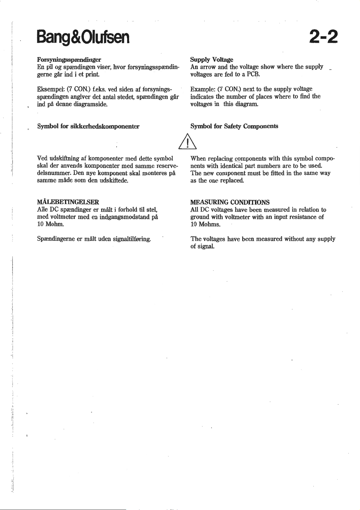
Forsyningsspaendinger
En pil
og
sprendingen viser, hvor forsyningssprendin-
et
gerne gar ind i
Eksempel: (7
sprendingen angiver det antal stedet, sprendingen
ind pa denne diagramside.
print
CON.)
f.eks. ved siden
af
forsynings-
Symbol for sikkerhedskomponenter
Ved udskiftning
der
skal
delsnummer. Den nye komponent skal monteres
samme
M.ALEBETINGELSER
Alle DC sprendinger
med voltmeter med en indgangsmodstand
10 Mohm.
anvends komponenter med
made som den udskiftede.
af
komponenter med dette symbol
samme
er
malt i forhold
til
stel,
pa
reserve-
gar
pa
Supply Voltage
An arrow and the voltage show where the supply
voltages are fed to a
Example:
indicates
voltages in this diagram.
(7
CON.)
the
number of places where to find
PCB.
next to
the
supply voltage
the
Symbol for Safety Components
When replacing
nents with identical
The
new component must
as
the
one replaced.
MEASURING
All DC voltages have been measured in relation to
ground with voltmeter with
10 Mohms.
~omponents
part
with this symbol compo-
numbers
be
fitted in
CONDITIONS
an
input resistance of
are
to be used.
the
same
way
..
Sprendingerne
er
matt uden signaltilf0ring.
The
voltages have been measured without any supply
of signal.
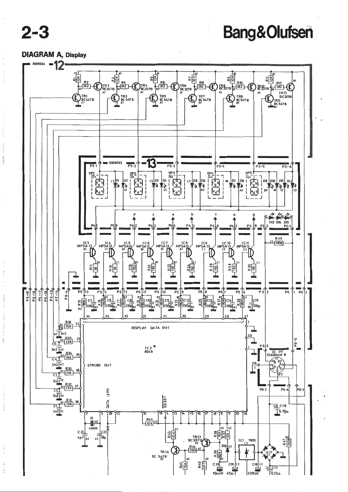
2-3
Bang&Oiufsen
DIAGRAM
8006024
-12-----------------------------------------
A,
Display
PJ-2
-
DPZ
fiJ-
- 1
02
I
~abll
9
~I
t
-':
I
fd'1
L =-:_J
d
..
0
03
~
I
c
b
a
9
"'
I
"'
n.
""
I
n.
"'
....
.
n.
"'
~
"'
-
PS
1
<0
n.
-
'!'
PS 3
-
:!
"'
'
'
n.
"'
n.
"'
DISPLAV DATA
so•9
STROBE OUT
IC2
OUT
•
Bang&Oiufsen
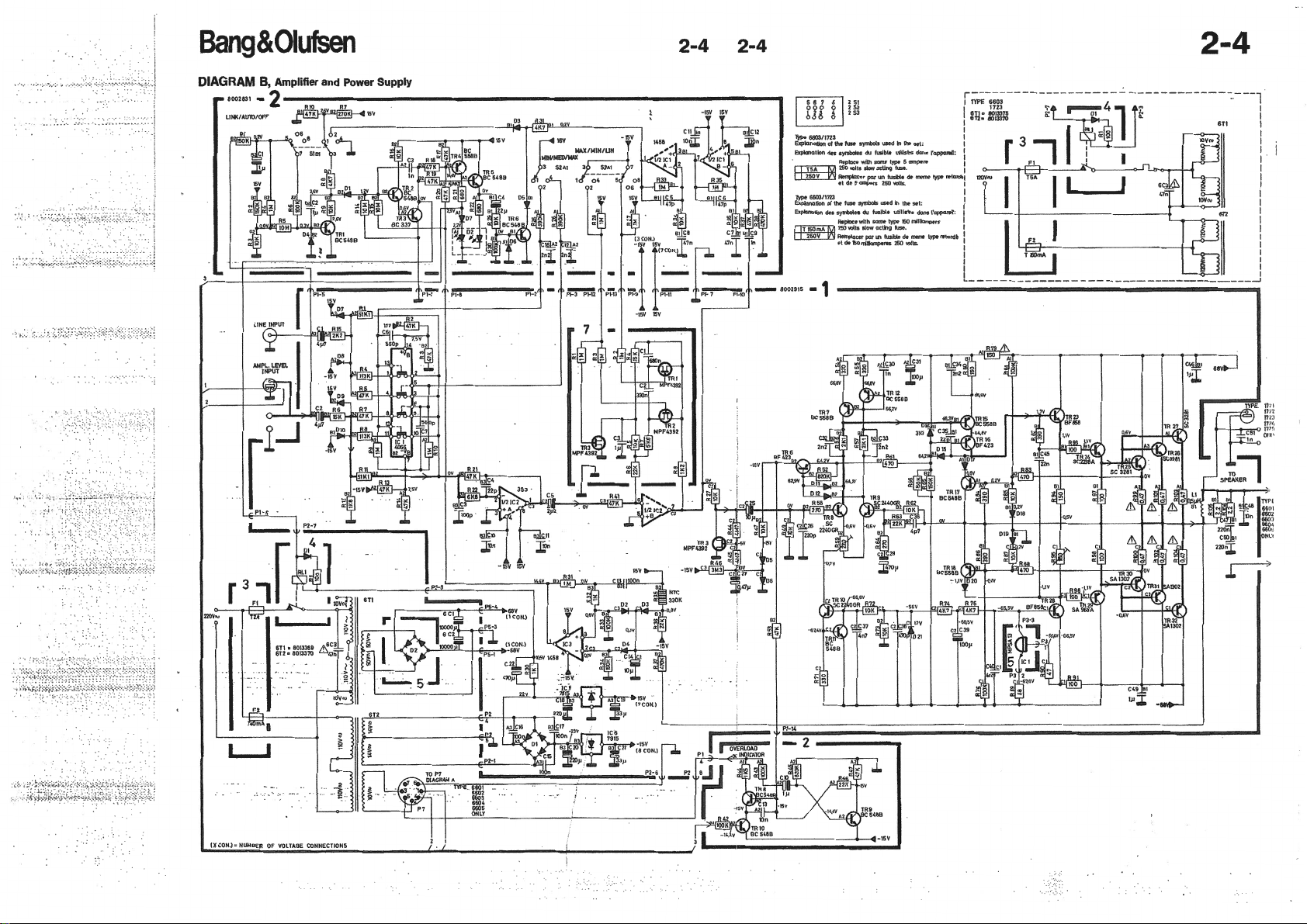
2-4
2-4
2-4
'.,.:;·.
.·::
DIAGRAM B, Amplifier
800
3
~1-
4!--~~--~------------------------------------------------------------,
and Power
Supply
M-3 P
-
~~
~-
.::::.-·--
.
"""':::--_ , ·-'
~....:::.--""'-
-
EJ:~~~:p
IJC
OI<l o_!j£
8
_,!"
I"r,co
~
J:
'
"E
.~;f·
-
- I
Pl'iJT r,'
,_.U
~
..
.
9
I~~l
J.
- I
;:r-----'
·Y P).-
10
~
"-""'K' ,....._,.,,.H
11'
-8002915
ZS\
--
····-·
..
:.::.
:::.
-
"'''
"''::
.";,.,"':.'.:."
~
Uwo
fuw
,...,.,.,.,
'"""' o>ll
~~M:~~-=-..:~=~
···=-~·
-1
:.::.:;
.::-
r~~~;
- -
1
6T1
'
.,....
' 1
: '
I '
""~'-:
1
I I
I
::-"
i
-
-·
: "
:
I
'-----
--------
•
i.Ji'
----------
--
- '
-
- - - - -
---
- - -----
--
·
---
----
"'
'
___
- g
__J
rl_J
Pl
-6
L-
P2-7
-·
IXCOtU •
NUMBER
OF
VOlTAGE
~
CONNECTIONS
 Loading...