

Page 1

HDR 1
Type 4640, 4641, 4642
Service Manual
English
German, French, Italian, Spanish, Danish and Dutch versions
are available in the Retail System
This Service Manual must be returned
with the defective parts/back-up suitcase !
Page 2

CONTENTS
Survey of modules .................................................................. 1.1
How to service ........................................................................ 1.2
Fault flow
chart ......................................................................... 2
Adjustments and configuration ............................................ 3.1
Final check after repair .......................................................... 3.3
Service menu .......................................................................... 3.5
Service mode .......................................................................... 3.6
Codec menu ............................................................................ 3.9
ServiceTool ............................................................................ 3.11
Remove cover ......................................................................... 4.1
Replacement of modules .............................................. 4.2 - 4.5
Specification
guidelines for service use ................................ 5.1
Type survey ............................................................................. 5.2
Wiring diagram ......................................................................... 6
Available parts ...........................................................................
7
Page 3
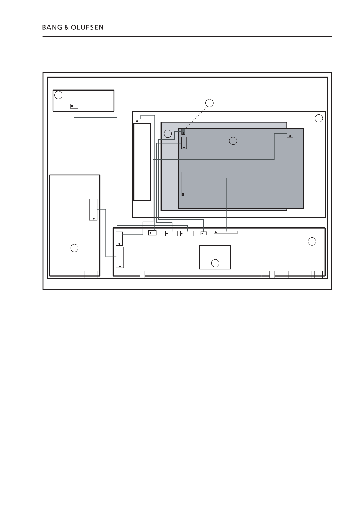
Power supply board
A/V board
Display board
FAN
MAINS
SCART
Tuner
2
1
3
DATA
(Mini jack)
P7
P4
P11
10
TU 1+2
P3
P13
Y/C Input
P2
P12
P1
P2
P1
P5
P8
HD unit complete
998
HD Drive
4
Codec board
5
P13
NTC
P10
HD power
µProcessor
board
6
7
Page 4

The HDR 1 is to be serviced in the customer’s home.
The static-protective fi eld service kit must always be used when the product is
The repair involves replacement of the HD unit, module(s) or fan.
The replaced modules must be returned for repair at Bang & Olufsen, Module
The EEPROM 6IC6 must be transferred to the A/V board in the HDR 1, hereby
The ServiceTool is required in several service situations, e.g. update of SW.
Always remember to download the latest version of the Service Manual.
The error code contains data that may be used for repairing the module(s) and
4. Before returning the HDR 1 to the customer, clear the error code.
White gloves.
w to service
Page 5
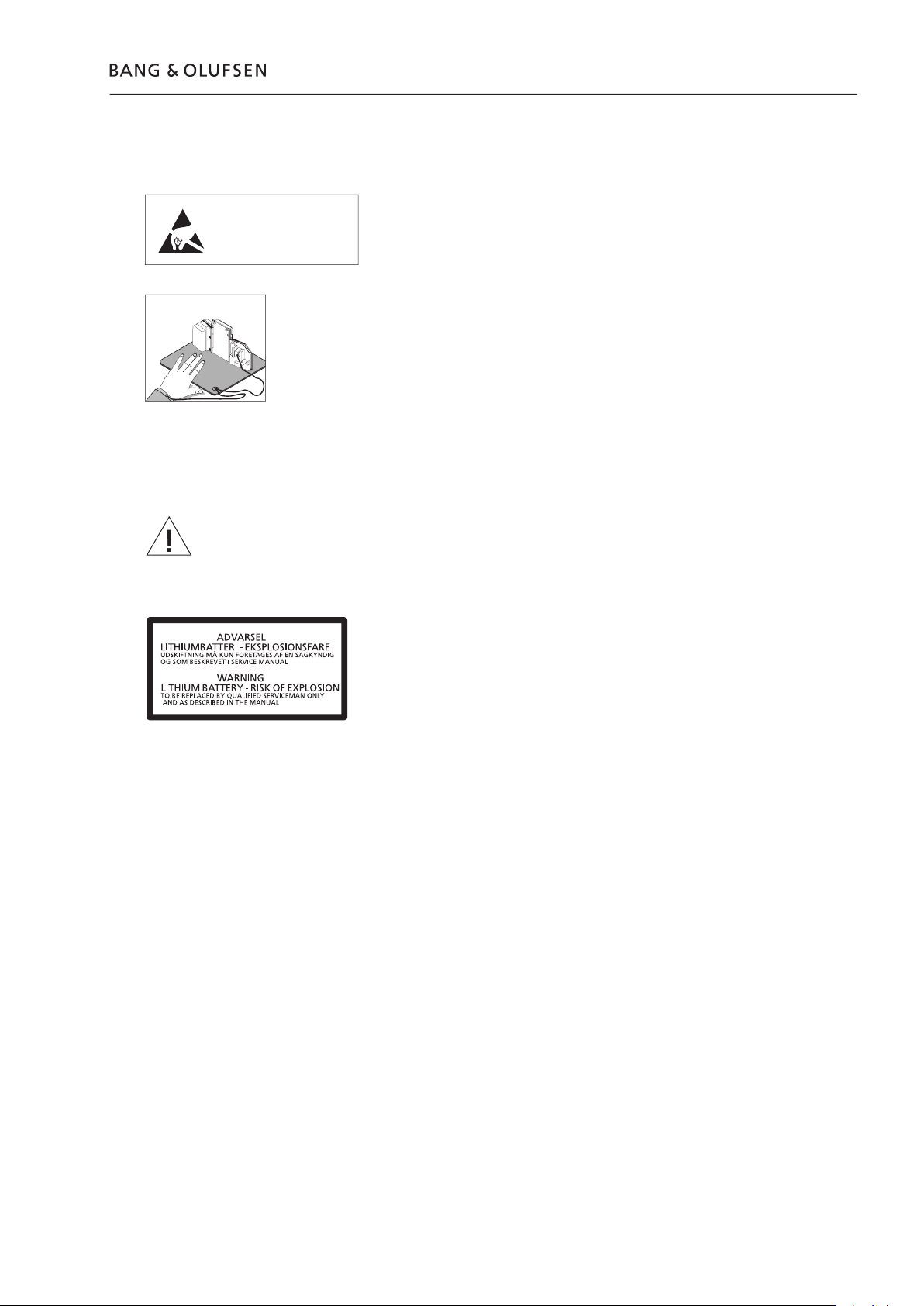
A static-protective fi eld service kit must always be used when the product is
When mains voltage on the product is required, remove the connection between
the product and the ESD-mat.
The chassis or modules must always be connected to the static-protective fi eld
service kit or placed in an ESD-proof bag.
When replacing components with this symbol, the same type has to be used, also
the same values for ohm and watt.
The new component is to be mounted in the same way as the replaced one.
WARNING
violent explosion.
Transport and handling
STATIC ELECTRICITY
MAY DESTROY THE
PRODUCT
ESD
Page 6

Page 7
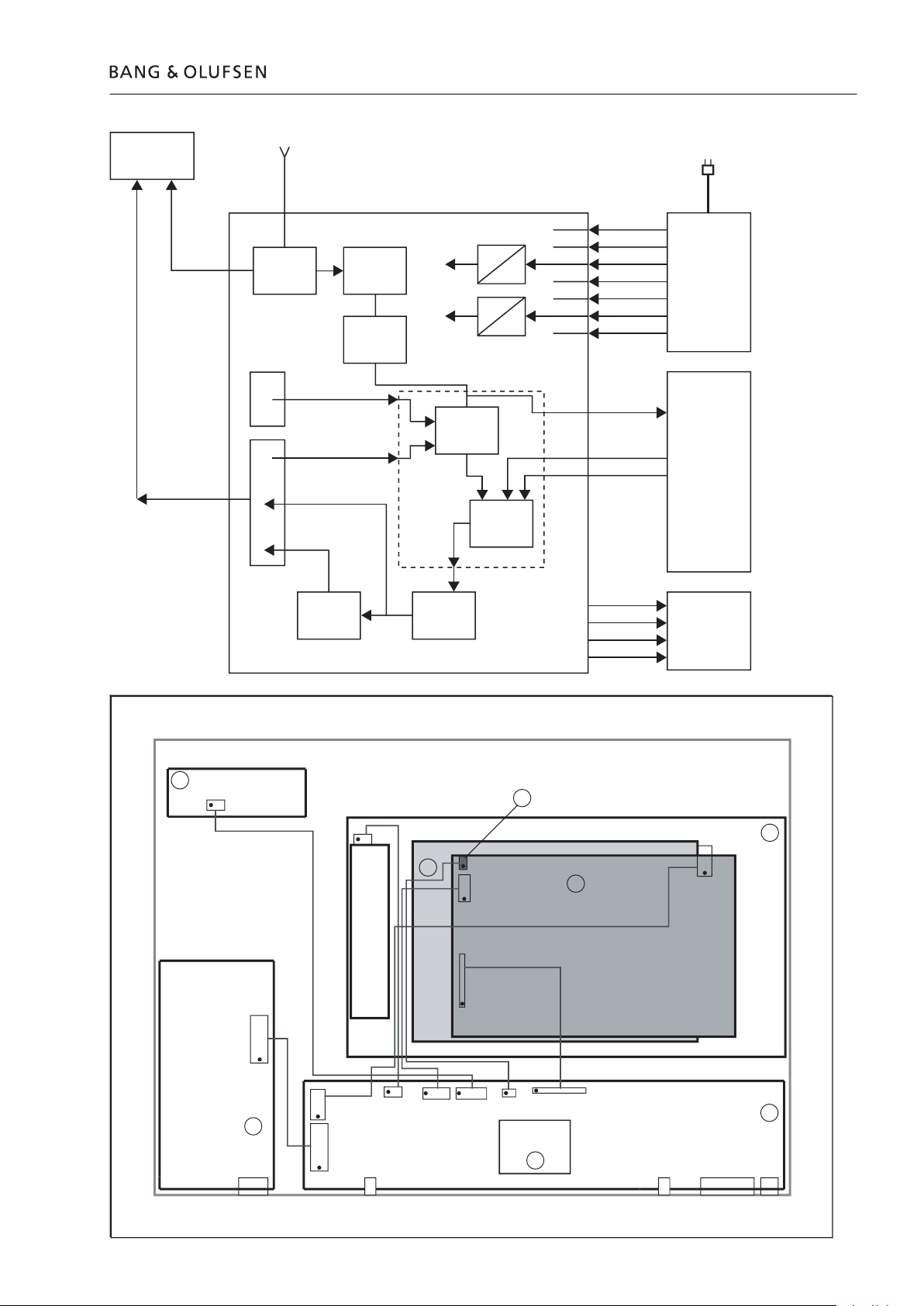
HD unit
Display
Splitter Tuner
IF +
DEMOD
Switch
Video
processor
Encoder
Y/C
A/V Board
BeoVision
Power supply
5V SB
+12V
+40V
+8V
-8V
+3.3V
+5V
32V
40V
2.5V
3.3V
CVBS
CVBS
RGB
+5V
Standby
Timer
Record
Ant out
RGB
Y/C
Scart
Ant in
Power supply board
A/V Board
Display board
FAN
MAINS
SCART
Tuner
02
01
03
DATA
(Mini jack)
P7
P4
P11
P10
TU 1+2
P3
P13
Y/C Input
P2
P12
P1
P2
P1
P5
P8
HD unit complete
998
HD Drive
04
Codec board
05
P13
NTC
P10
HD power
Processor
board
06
07
(X1)
(O200)
(X12)
(X8)
(X10)
(X5) (X11)
(X4)
(X7)
(X10)
(X13)
Page 8
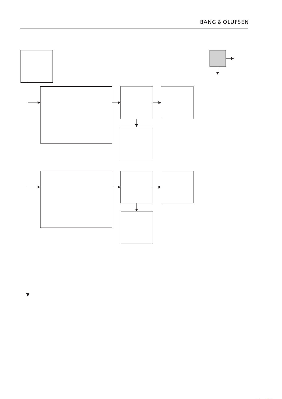
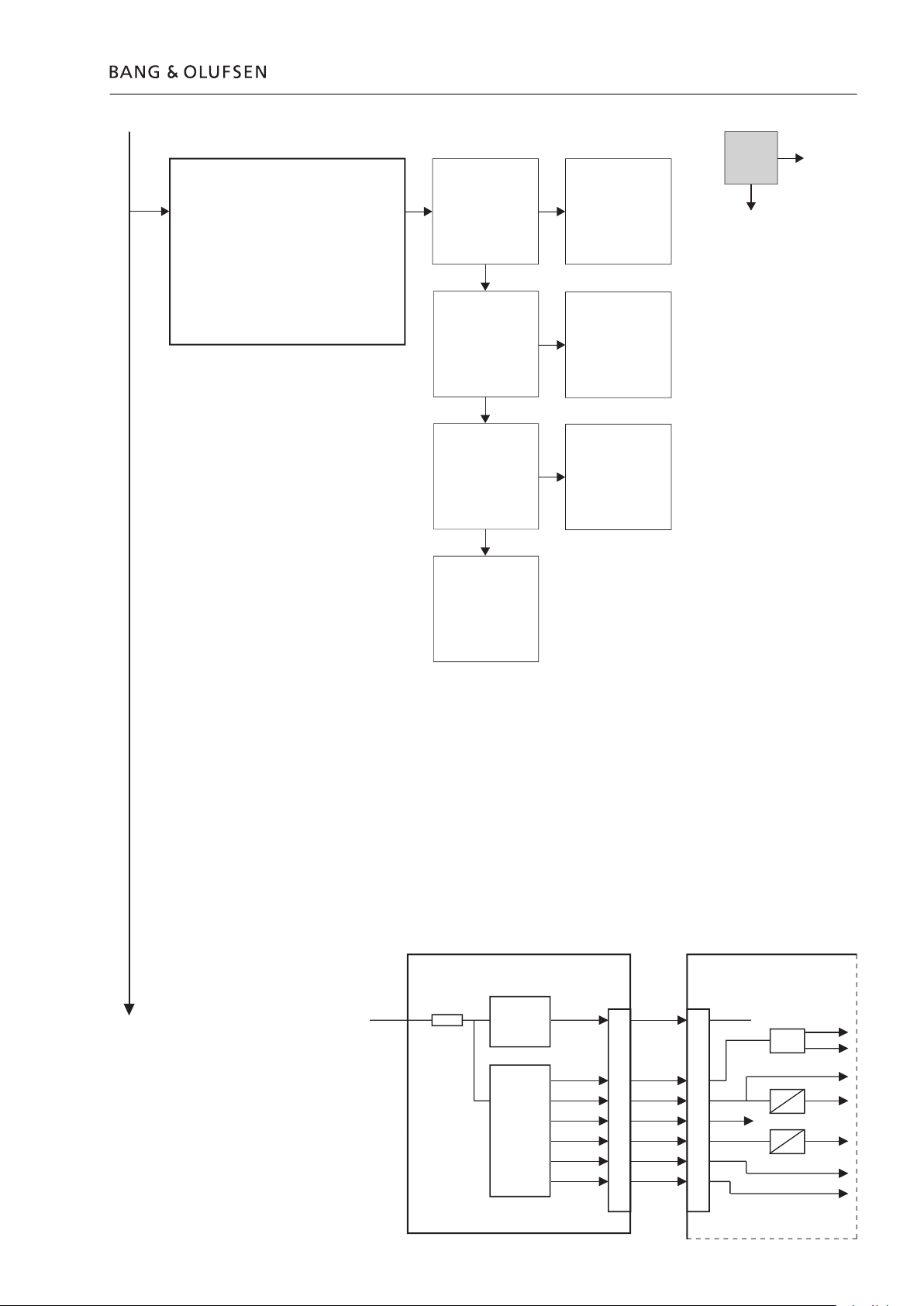
- TV: Fault
- V.Tuner: OK
- HD: OK
- Splitter defect
- Splitter circuit on A/V board
Ant out -> TV
connection
- TV: Fault
- V.Tuner: Fault
- HD: OK
- Splitter defect
- Splitter circuit on A/V board
Antenna -> Ant input
connection
Yes
Page 9
- TV: Fault
- V.Tuner: Fault
- HD: Fault
- Power supply defect
- A/V board defect
Apply mains
- - - - - - - -
Yes
A/V Board
PCB2
Power supply
PCB1
2
W
+12V+12V
+5V
+5V
+3.3V
+5V_A
+5V_D
+2.5V
+3.3V
+3.3V
+2.5V
+40V
+40V
+32V
+8V
+8V
-8V
-8V
+32V
+5V_SB+5V_SBMains
Fuse
O200
Page 10
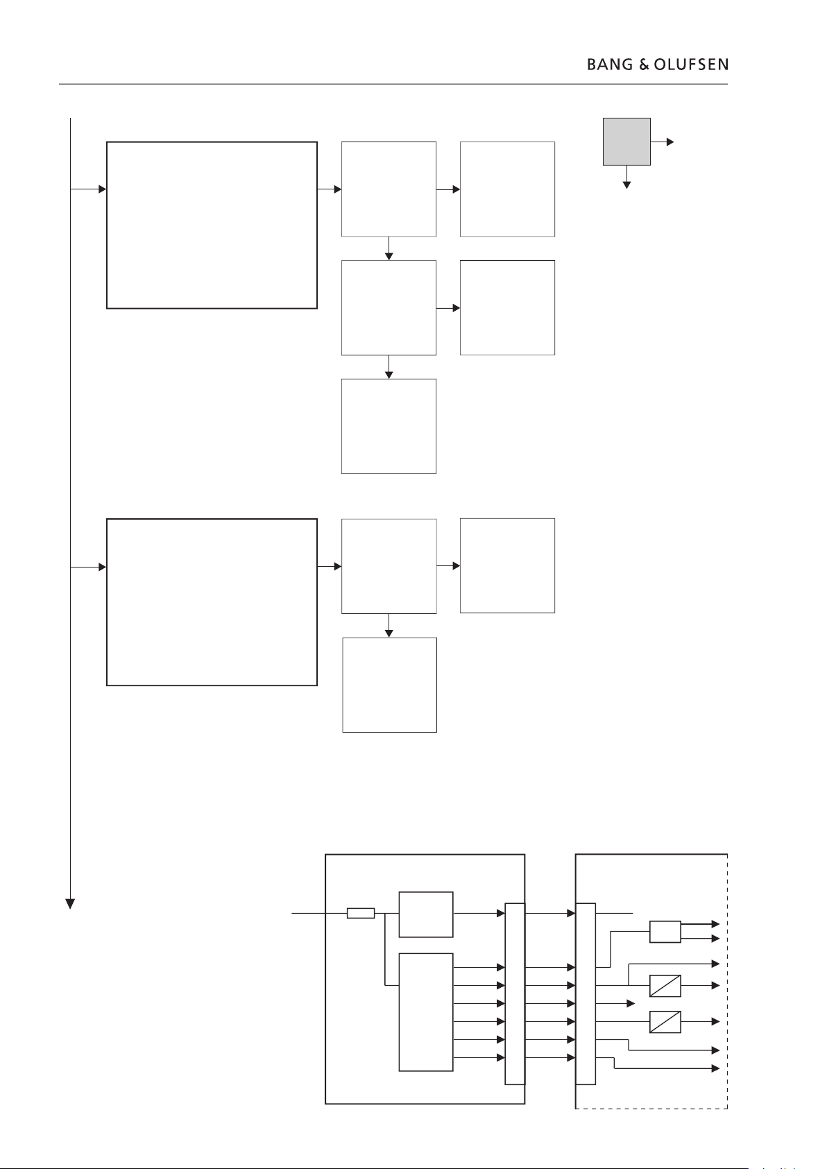
- TV: OK
- V.Tuner: Fault
- HD: Fault
- Connection HDR 1 - TV failure
- Power supply failure
- A/V board failure
- - - - - - - -
connection
- TV: OK
- V.Tuner: Fault
- HD: OK
- Power supply failure
- A/V board failure
output
Yes
output
- - - - - - - -
A/V Board
PCB2
Power supply
PCB1
2
W
+12V+12V
+5V
+5V
+3.3V
+5V_A
+5V_D
+2.5V
+3.3V
+3.3V
+2.5V
+40V
+40V
+32V
+8V
+8V
-8V
-8V
+32V
+5V_SB+5V_SBMains
Fuse
O200
Page 11
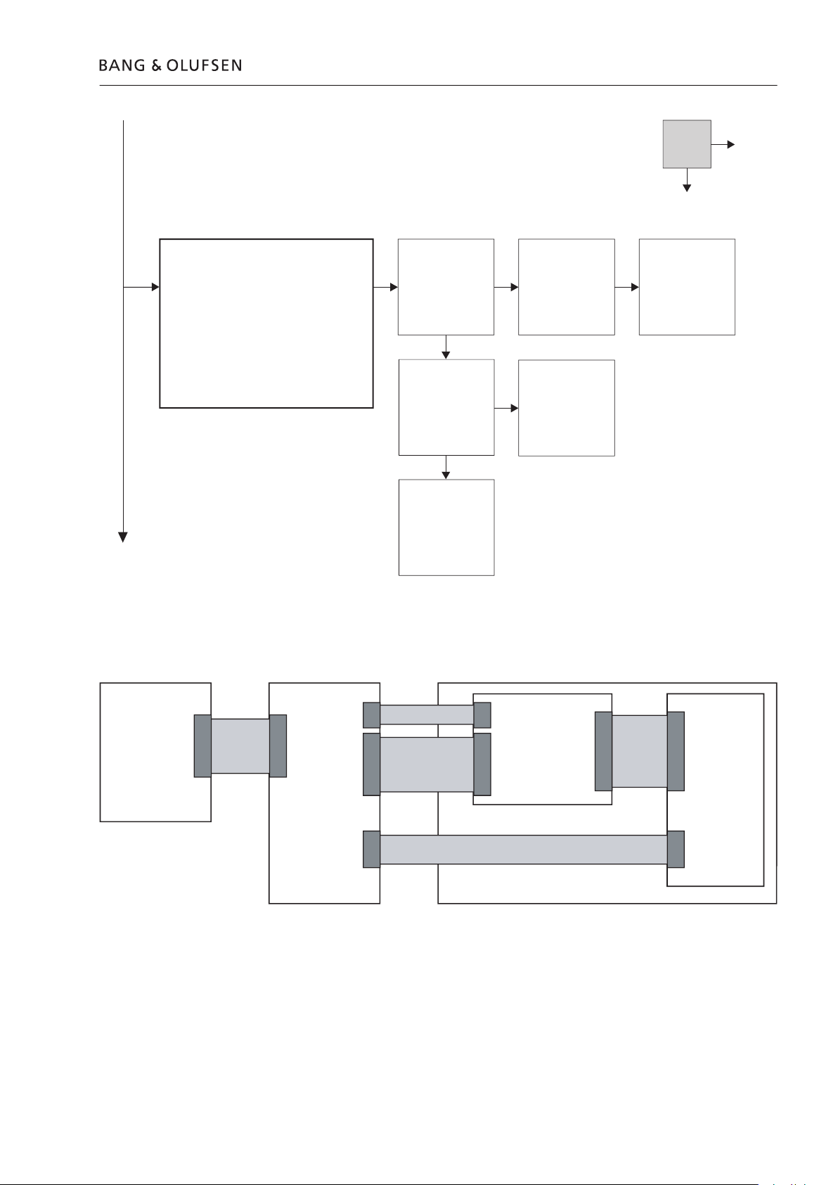
Power supply
PCB1
A/V Board
PCB2
Hard dis
cCodec
HD unit
Module 998
2
W
1
W
3
W
7
W
8
W
Voltage
Voltage
Voltage
Voltage
Video
Audi
o
I3C
- TV: OK
- V.Tuner: OK
- HD: Fault
- HD unit
- Connection to HD unit
s
- - - - - - - -
connection to
connection
Yes
Page 12
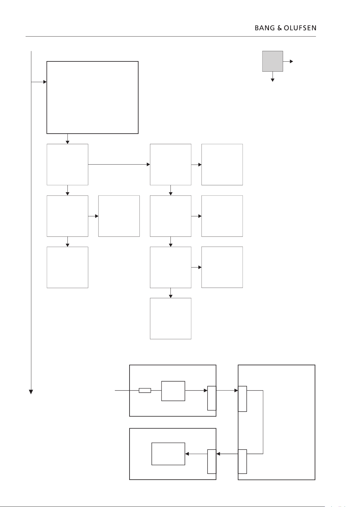
- HDR 1 display - no or missing light
- No power
- Display board failure
connected and
applied
- - - - - - - -
- - - - - - - -
Yes
- - - - - - - -
A/V Board, PCB2
Power supply, PCB1
2
W
+5V_SB
Mains
Fuse
Display board, PCB3
5
W
+5V_SB
9 9
11
Red/Green
standby led
O200
X1 X11
X12
Page 13

- OSD Warning
“The hard disc recorder is overheating
please switch it to standby”
- Standby light = blinking red/green
- NTC function
- NTC PCB defect
- W6 cable to NTC PCB defect
- FAN function
- FAN defect
- FAN circuit defect
- - - - - - - -
connection
- - - - - - - -
A/V board defect
Visual check of FAN
Yes
- - - - - - - -
connection
on A/V board X10 pin
8V: normal operation
8.5V: no load
A/V board defect,
A/V Board, PCB2
Power supply,
PCB1
2
W
4
W
NTC, PCB7
6
W
+5V_A
NTC_VNTC
2
1
X4
X12 X10
+12V
FAN_level
uPH8_FAN_I
N
FAN
1
2
3
DC/DC
+5V_A
Vref
Vntc
FAN_out
FAN_in
Microprocessor, PCB6
Page 14

Page 15

Adjustments
3.1
Adjustments and confi guration
sel
Activate
activate selected menu
return to the previous menu
exit service mode
Adjust
l
n
change valu
Adjustment in picture adjustment is not necessary.
All values are factory adjusted for optimum performance.
Page 16

TUNER SYSTEM B/G ON
L OFF
M OFF
D/K OFF
I OFF
AFC OFF
VHF-1 CONSTANT 162
VHF-2 CONSTANT 148
TUNER TAKEOVER 26
AFC STATUS O/L
AFC ON
AFC is always on during normal operation.
AFC OFF
AFC OFF is obtained by
This function is only necessary if the HDR tuner is to be adjusted manually.
TUNER TAKEOVER, IF ADJUST & FM SOUND ADJUST
GO.
The data are transferred.
The menu shifts to SERVICE MENU.
Page 17

The fi nal check after repair, describes the activities that are needed to ensure the
The contents are:
when the set has been reassembled and is ready to be returned to the customer.
Flashovers must not occur during the testing procedure!
terminals of the insulation tester. Connect the other terminal to ground on the
To avoid damaging the HDR 1 it is essential that both terminals of the insulation
tester have good contact.
The scope of this check is, to ensure the following:
3.3
Page 18

setup, due to procedures in the service manual, such as Connections, Replay,
Tuning
Wipe dust off the surfaces using a dry, soft cloth. Remove grease stains or persistent
Page 19

SERVICE MENU
AV
BOARD
HDR TUNER
CODEC MENU
AV BOARD MENU
H8 INFORMATION
IC INFORMATION
SERVICE COUNTERS
PICTURE ADJUSTMENTS
GEOMETRY ADJUSTMENTS
M2 INFORMATION
TIMER RECORDING INFO
RESET TO DEFAULT
VIDEO OUT
IC INFORMATION
MSP
HIP
HOP
02040A24
11
14
SERVICE COUNTERS
POWER ON
PLAY (DAYS) 1
RECORD
REPLA
Y
(DAYS)
0
(DAYS)
2
(DAYS)
1
PICTURE ADJUSTMENTS
CURRENT VALUES
BRILLIANCE 13
COLOUR 13
CONTRAST 20
R-DR 32
G-DR 32
B-DR 32
BLACK OFFSET R
6
BLACK OFFSET G
8
GEOMETRY ADJUSTMENTS
BLANKING 0
H-PH 30
H-AM 30
V-AM 30
V-
SL 30
V-
SH 20
V-
SC 20
EW-P 30
EWUC 30
EWLC 30
EW-T 30
H-PA 30
BOW 30
EHT 20
V-
ZO 20
VSCR 20
V-WA 20
H-CENTER 20
TUNER SYSTEM B/G ON
L
M
D/K
I
OFF
OFF
OFF
OFF
AFC
LOW TUN RANGE
HIGH TUN RANGE
LOWER BAND LIMIT
UPPER BAND LIMIT
VHF-1 CONSTANT
VHF-2 CONST
ANT
UHF CONSTANT
TUNER TAKEOVER
IF ADJUST
AFC STATUS
FM SOUND ADJUST 21
ON
45
860
170
450
162
148
49
27
63
O/H
TV SER
VICE MENU
M2 INFORMA
TION
HW
92.00a
M2
M2 BOOT 92.00a
STB TABLES 03.00a
STB TIMER 0
CN SOUND OFF
LOAD FREQUENCY 210
RESET TO DEFAULT
TIMER RECORDING INFO
PROGRAMMED:
TV1 0107 2050 2100 VPT
EXECUTED:
TV1 0107 2050 2100 VPT
ERROR:
NO ERROR
PROGRAMMED:
SAT 0207 2050 2100 MENU
EXECUTED:
SAT 0207 2050 2100 MENU
ERROR:
NO ERROR
PROGRAMMED:
TV3 0207 2150 2300 VPT
EXECUTED:
TV3 0207 2150 2300 VPT
ERROR:
SIGNAL MISSIN
G
H-PH 30
H8 INFORMATION
06 IC3 AP SW 1.0
06 IC2 IOP SW 22.0
TYPE NO. 4640
ITEM NO. XXXXXXX
SERIAL NO. XXXXXXXX
ERROR: HDR . . . . . . . . .
HDR . . . . . . . .
.
HDR . . . . . . . .
.
HDR . . . . . . . .
.
HDR . . . . . . . .
.
HDR
TV AVL LAST . . . . .
VA
UX AVL LAST . . . . .
RESTORE USER SETTINGS
RESET TO DEFAULTS
OUTPUT RGB ON
VIDEO OUT
10 IC207 2.550
INTERNAL TEMPERATURE 34C
RESTORE RECORDINGS
CLEAR HDD
HDD VALUES
RESET TO DEFAUL
T
CODEC MENU
STANDARD Q. REC QUALITY 40
HIGH Q. REC QUALITY 85
HDD SIZE (GB) 76
HDD VALUES
R-DR 32
3.5
Page 20

AV BOARD MENU
The PICTURE ADJUSTMENTS and GEOMETRY ADJUSTMENTS lines are described in
the section on adjustments.
The 5 latest HDR 1 errors are shown as error codes and displayed with the month/
top.
XX-YZ (XX = IIC address
Y = IIC bus 1 or bus 2
Z = any IIC bus segment A/B/C/D)
AVL error codes from the TV and VAUX sockets
TI Transmission impossible
TD Data link tied down
After repair of an error that has triggered the display of an error code, the error code
in the H8 INFORMATION menu.
An IIC bus error means that the communication on the bus fails when the
the bus. Adresses in connection with IIC bus errors:
Error code Module IC Function BUS
22 2 D21 SDA6000 M2 Processor IIC-1
8A 2 D23 TDA9321H Colour decoder & IF (HIP) IIC-2A
8C 2 D25 TDA9330H Video processor (HOP) IIC-2A
80 2 D3 MSP3415G (type 4640) Sound processor IIC-2B
84 2 D3 MSP3415G (type 4642) Sound processor IIC-2B
88 2 D3 MSP3415G (type 4641) Sound processor IIC-2B
A2 2 D17 PCF8563TF Real-time clock IIC-2C1
C0 2 TU1 CTF5510 Tuner IIC-2A
A4 2 D1 M24C02 AV Board EEPROM IIC-2C
60 5 CODEC FEP IIC-2B
Page 21

3.7
The values are stored in the EEPROM. If faulty readings of the values in the EEPROM
The line shows the software version for conversion of Set-top Box remote control
The software is programmed into the M2 processor and the information will
with certain Set-top Boxes.
TIMER RECORDING INFO
After RESTORE USER SETTINGS set HDR 1 into St. by and then switch it on again.
The user is prompt to go through the SETUP menu, as all SETUP’s are set to default.
VIDEO OUT
Page 22

TV SERVICE MENU
standard). This is done to reduce the tuning time.
AFC ON/OFF is used in connection with adjustments but it may also be useful in
The AFC is set to ON when the HDR1 has been turned off by means of the mains
switch.
The function is only working in combination with the tuner system D/K.
the Processor Board (PCB6).
VHF-1 CONSTANT 161
VHF-2 CONSTANT 146
These items are for factory use.
TUNER TAKEOVER 26
AFC STATUS O/H
These items are described in the section on adjustments.
Page 23

3.9
When the temperature is between 53 – 56 °C a warning is displayed.
This function may be used if the 6IC6 has been replaced or the HD unit is replaced.
All recordings that are stored on the HDD are indexed in the index in the EEPROM,
1. Turn off HDR 1.
2. Turn on HDR 1.
Press
on Beo4.
3. Select
in SELECT SOURCE.
4. Select
in MENU.
5. Enter Service Menu.
Press
6. Select
in SERVICE MENU.
7. Select
When the HDD is cleared the HDR 1 returns to SERVICE MENU.
8. Select
in SERVICE MENU.
9. Select
When the recordings are restored the HDR 1 returns to SERVICE MENU.
Exit the SERVICE MENU by pressing
on the Beo4.
Verify the HDD is empty.
If the HDD is not empty return to step 1 and restart the CLEAR HDD.
Do not boot the HDR 1 by removing the mains supply.
Page 24

Page 25

Tool
3.11
The ServiceTool will contain the complete information concerning:
The ServiceTool does not contain:
Page 26

Page 27

4.1
Remove cover
Remove screws on sides
Remove screws on back
ESD
ESD-Mat
Pull off cover
2x
TX10
4x
TX10
Page 28

4.2
Replace PCB3, Display board
Pull out front
Remove screws
3P01
Remove plug
2x
TX10
4.1 Remove cover
Page 29

TX10
TX10
4.1 Remove cover
IC6
EEPROM
IC3
App. SW
PCB6
IC
SOCKET
TUNER TAKEOVER, IF ADJUST & FM SOUND
ADJUST. Refer to Adjustments.
Page 30

4.4
Replace PCB1, Power supply board
5x
TX10
1P200
Pull out Power supply board
Remove screws
Remove plug
4.1 Remove cover
Page 31

TX10
4.1 Remove cover
TX10
Access the CODEC MENU in the Service menu.
Page 32

4.6
Page 33

SPECIFICATION GUIDELINES FOR SERVICE USE HDR 1
CTV system *See type survey
Cabinet finish Black/Silver
Terminal recommended via BeoVision Beo4
Video PAL, SECAM, NTSC colour decoder
HDD 80Gb
Record and playback Simultaneous
Playing time High Q, 20 hours / Standard Q, 45 hours
Number of Timer Recordings Max. 15
Sound Analog audio (Mono, A2, Nicam)
Menu National language on menus (UK, D, F, I, E, NL, DK, S)
Signal-to-noise-ratio Typical 110 dB, A weighted, in Audio mode
Dimensions W x H x D 38 x 9.7 x 28 cm
Weight 4.0 kg
Power supply 195 - 265 volts 50/60 Hz
Power consumption Typical 21 watts / St-By < 1 watt
16:9 detection on both scart connectors
Set-top Box controller (STB-C) Built-in
CONNECTIONS
TV & AUX Pin 1 Audio R out 1V RMS 150 ohms
Pin 2 Audio R in 1V RMS 40 kohms
Pin 3 Audio L out 1V RMS 150 ohms
Pin 4 Audio GND
Pin 5 Blue GND
Pin 6 Audio L in 1V RMS 40 kohms
Pin 7 Blue 0.7 Vpp 75 ohms (out TV) (in AUX)
Pin 8 16:9/4:3 info
AVL 2 way (TV)
AVL 1 way (AUX)
Pin 9 Green GND
Pin 10 Not used
Pin 11 Green 0.7 Vpp 75 ohms (out TV) (in AUX)
Pin 12 Not used
Pin 13 Red GND
Pin 14 Blanking GND
Pin 15 Red 0.7 Vpp 75 ohms (out TV) (in AUX)
Pin 16 Blanking Logic 0 = 0V to 0.4V (out TV) (in AUX)
Logic 1 = 1V to 3V
R in 75 ohms
Pin 17 Video out GND
Pin 18 Video in GND
Pin 19 Composite video out 1 Vpp 75 ohms
Pin 20 Composite video in 1 Vpp 75 ohms
Pin 21 Shield
Y/C INPUT Pin 1 Y GND
Pin 2 C GND
Pin 3 Luminance in (Y) 1 Vpp 75 ohms
Pin 4 Chrominance in (C) 1 Vpp 75 ohms
Auto config if Y/C signal is present
DATA Mini jack 3.5 mm Control of Set-top Box and SW update for M2
processor
Aerial Coax aerial in 75 ohms
TV Coax aerial out 75 ohms
Subject to change without notice
Specification guidelines for service use 5.1
Page 34

5.2 Type survey
Type survey
Modification to other TV systems
Type Chassis System Market B/G B/G,L/L’,D/K,I B/G,M,D/K,I
4640 NEU B/G Australia, Austria, Belgium, Croatia, Denmark, Finland, 8001699 8001696
Germany, Greece, Holland, Israel, Italy, Kuwait,
New Zealand, Norway, Oman, Portugal, Slovenia, Spain,
Sweden, Turkey, United Arab Emirates, Indonesia, Malaysia,
Singapore, Thailand
4641 HK B/G,M,D/K,I Hong Kong, China 8001699
4642 FGB B/G,L/L’,D/K,I Bahrain, Egypt, France, Lebanon, Qatar, Saudi Arabia,
Switzerland, Czech Repub., Hungary, Poland, Slovak, 8001696
Russia, Morocco, South Afrika, UK
Page 35

Wiring diagram 6.1
X5
>
>
>
>
>
>
>
<
<
<
<
>
>
>
>
<
<>
>
>
>
>
<
<
<
<
>
>
>
<
>
>
>
>
>
>
>
>
X7
>
>
>
>
X8
<
>
>
X10
X14
<
<
<
<
>
<
<>
<
<
<
>
>
>
>
>
>
<
>
<
<
<
<
><
><
><
XP3
XP4
X11
<
<
<
<
<
<
X4
>
<
X12
<
>
>
>
>
>
>
>
>
>
>
>
>
>
>
0200
>
>
>
>
>
>
>
>
>
<
>
>
>
>
>
X1
<
<
<
<
<
<
W9
6200080
W10
6200080
P2
<
<
<
<
>
<
<>
<
<
<
>
>
>
>
>
>
<
>
<
<
<
<
XX
><
><
><
P1
7211357
>
>
>
>
>
>
<
>
<
<
<
<
<
<
<
<>
<
<>
>
<
<
>
>
>
>
X1
>
>
>
>
>
>
<
>
<
<
<
<
<
<
<
<>
<
<>
>
<
<
>
>
>
>
X10
>
>
>
>
>
>
>
>
<
>
>
>
<
<
<
<
>
>
>
>
<>
<
>
>
>
>
<
<
<
<
>
>
>
>
>
>
>
X13
>
<>
<>
<>
<>
<>
<>
<>
<>
<>
<>
<>
<>
<>
<>
<>
<>
>
>
>
>
>
>
>
>
>
<
<
<
<
<>
<
>
>
<
>
<
>
>
>
>
>
<>
<>
<>
<>
<>
<>
<>
<>
<>
<>
<>
<>
<>
<>
<>
<>
>
>
>
>
>
>
>
>
>
<
<
<
<
<>
<
>
>
<
>
<
W1
>
<
W6
6277054
W2
6277044
W3
6277047
W5
6277051
W7
6200063
W8
6277055
W4
Solder
>
>
<
FAN
Codec Board
05
AV BOARD
02
Power Supply Board
01
Display Board
03
06
uProcessor Board
HD Drive
04
07
NTC Board
>
W11
998
HD Unit complete (pcb 4 & pcb 5)
Debug Connector
(For development purpose only)
Debug Connector
(For development purpose only)
Page 36

Available parts 7.1
AVAILABLE PARTS
6100328 Mains lead GB
6100248 Mains lead AUS
6100040 Mains lead CN
8001696 PCB2, A/V Board BGMIDKL incl. PCB6
8001699 PCB2, A/V Board BGLL’IDK incl. PCB6
PCB
µProcessor Board
is not available
as spare part
Wire bundles
The part no. is printed on the diagram above the wire bundle, as shown.
3375258 Bag w/screws and washers
6270803 AV cable, 3m
6270070 Antenna cable, 3m
8330352 IR blaster f/external source
3395260 Back-up suitcase
3375073 Product cover
3396135 Set of foam
3392509 Outer carton
Available documentation
See Retail System
9001
9002
9003
9004
9005
9006
9007
9002
9008
9009
9010
1
1
1
1
1
1
1
1
2
4
3
2
4
3
2
4
3
5
6
7
6
6
1
1
1
1
1
1
1
1
1
1
1
6
6
8
8
5
4
7
998
2
6
1
3
Incl. pos. nos. 9005, 9006
4 2938008 Rubber damper
X5
>
>
>
>
>
>
>
>
>
>
>
>
>
>
X13
W3
6277047
Page 37

Page 38

Bang & Olufsen
DK-7600 Struer
Denmark
Phone +45 96 84 11 22*
Fax +45 97 85 39 11
3538021 04-05
 Loading...