

Page 1
Vulcan Series
Getting Started
ENGLISH
www.bandg.com
Page 2

Page 3

Contents
6 Introduction
6 The Home page
7 Application pages
9 Basic operation
9 System Controls dialog
9 Turning the system on and off
10 Selecting pages and panels
10 Adjusting panel size
11 Adding new favorite pages
11 Creating a Man Overboard waypoint
13 Charts
13 The Chart panel
14 Showing dual chart types
14 Panning the chart
14 Using the cursor on the panel
15 Positioning the vessel on the chart panel
16 Displaying information about chart items
17 Find objects on chart panels
17 3D charts
18 Waypoints, Routes, and Tracks
18 Waypoints
19 Routes
20 Tracks
21 Navigating
21 Navigate to cursor position
21 Navigate a route
21 Navigating with the autopilot
22 SailSteer panel
23 Selecting data fields for the SailSteer panel
23 Sail Time calculations
Contents | Vulcan Series Getting Started
3
Page 4

24 Race panel
24 Display options
24 Start Line on Chart panel
25 Time and Wind plots
25 The Time plot panel
25 Wind Plot panel
26 Autopilot
26 Safe operation with the autopilot
26 Activating the autopilot
26 Switching from automatic mode to manual steering
27 Autopilot indication on the pages
28 The Autopilot panel
29 Radar
29 The radar panel
30 Radar menu options
30 Adjust the radar image
31 View and Advanced options
31 Radar settings
32 Echosounder
32 The Echosounder image
33 Viewing Echosounder history
33 Setting up the image
34 StructureScan
34 The StructureScan image
35 Setting up the image
36 ForwardScan
36 The ForwardScan image
37 Setting up the image
37 Heading extension
39 Instrument panels
39 Dashboards
4
Contents | Vulcan Series Getting Started
Page 5

40 Wireless connection
40 Connect and disconnect from a wireless hotspot
41 Audio
41 Enabling audio
42 The Audio panel
42 Operating the audio system
43 Alarms
43 Alarm system
43 Alarms dialog
44 Tools
44 Waypoints/routes/tracks
44 Tides
44 Alarms
44 Settings
44 Vessels
45 Sun, Moon
45 Trip calculator
45 Files
45 Find
45 GoFree Shop
Contents | Vulcan Series Getting Started
5
Page 6
1
Introduction
This manual provides an overview of the product and its features.
For more detailed information about the features, functions and
options, refer to the Operator manual. You can access the Operator
manual from the Files option in the Tools panel, refer to "Files" on
page 45.
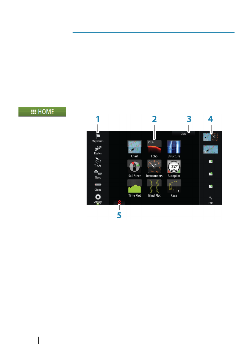
The Home page
The Home page is accessed from any operation by selecting the
Home button in the upper left corner of a panel.
1 Tools
Select a button to access dialogs used for carrying out a task,
or for browsing stored information.
2 Applications
Select a button to display the application as a full page
panel. Press and hold a button to display pre-configured
split page options for the application.
3 Close button
Select to exit the Home page and return to the previous
active page.
6
Introduction | Vulcan Series Getting Started
Page 7
4 Favorites
Select a button to display the panel combination.
Press and hold a favorite button to enter edit mode for the
Favorites panel.
5 Man Over Board (MOB) button
Select to save a Man Over Board (MOB) waypoint at the
current vessel position.
Application pages
Each application connected to the system is presented on panels.
The application can be presented as a full page, or in combination
with other panels in a multiple panel page.
All application pages are accessed from the Home page.
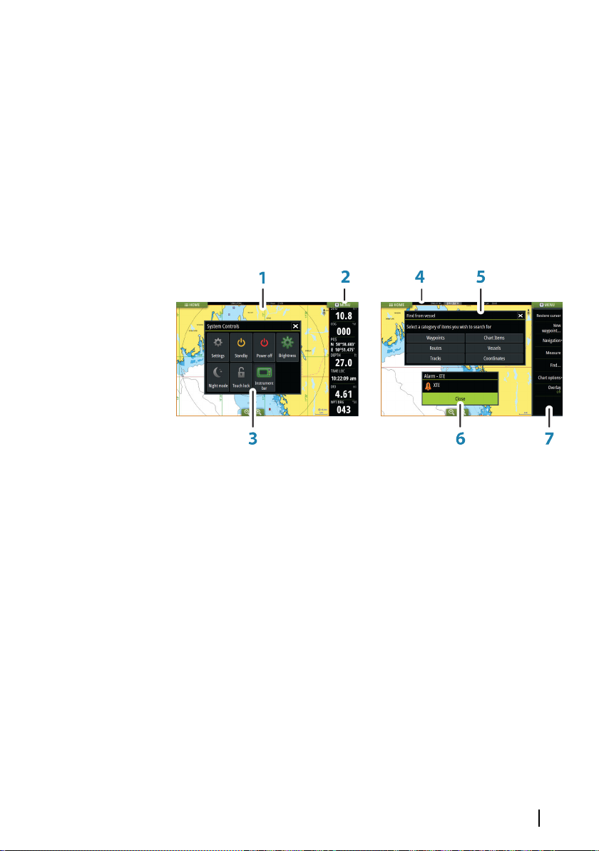
1 Application panel
2 Instrument bar
Navigation and sensor information. The bar can be turned
off and it can be configured by the user.
3 System controls dialog
Quick access to basic system settings.
Display the dialog by a short press on the Power key or by
swiping down from top of the screen.
4 Status bar
5 Dialog
Information to or input from the user.
Introduction | Vulcan Series Getting Started
7
Page 8
6 Alarm message
Displayed if dangerous situations or system faults occur.
7 Menu
Panel specific menu.
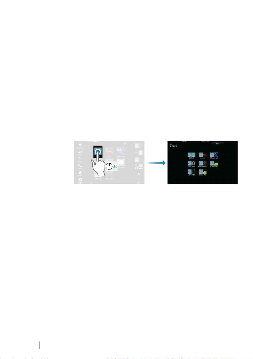
Pre-configured split pages
Each full screen application has several pre-configured split pages,
featuring the selected application combined with each of the other
panels.
Note: The number of pre-configured split pages cannot be
Ú
changed, and the pages cannot be customized or deleted.
Access a pre-configured split page by pressing and holding the
main panel button.
8
Introduction | Vulcan Series Getting Started
Page 9
2
Basic operation
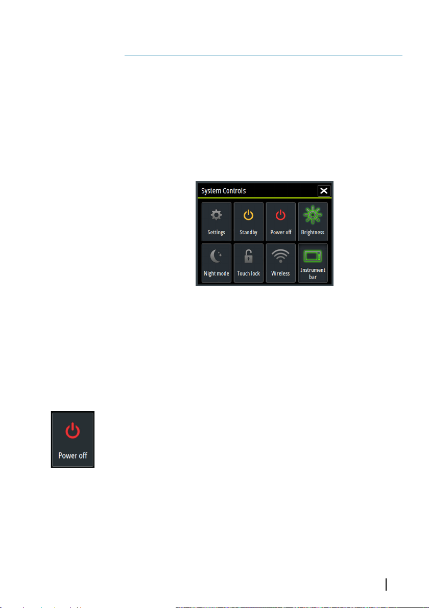
System Controls dialog
The System Controls dialog provides quick access to basic system
settings. You display the dialog by making a short press on the
Power key or by swiping down from the top of the screen.
The icons displayed on the dialog can vary. For example, the adjust
splits option is only available if you are viewing a split page when
you open the System Controls dialog.
Activating functions
Select the icon of the function you want to set or toggle on or off.
For those functions that toggle on and off, a highlighted icon
indicates the function is activated, as shown in the Instrument bar
icon above.
Turning the system on and off
You turn the system on and off by pressing and holding the Power
key. You can also turn the unit off from the System Controls
dialog.
If the Power key is released before the shut-down is completed, the
power off process is cancelled.
Basic operation | Vulcan Series Getting Started
9
Page 10
Selecting pages and panels
Selecting a page
• Select a full page panel by selecting the relevant application
button on the Home page
• Select a favorite page by selecting the relevant favorite button
• Select a predefined split panel by pressing and holding the
relevant application icon
Select active panel
In a multiple panel page, only one panel can be active at a time. The
active panel is outlined with a border.
You can only access the page menu of an active panel.
You activate a panel by tapping it.
Adjusting panel size
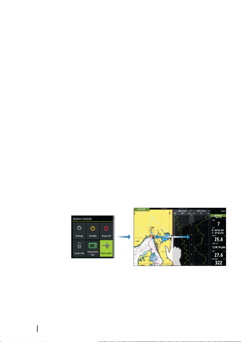
You can change the panel size for an active split page. The panel
size can be adjusted for both favorite pages and for predefined split
pages.
1. Activate the System Controls dialog
2. Select the adjust splits option in the dialog
3. Adjust the panel size by dragging the adjustment icon
4. Confirm your changes by tapping one of the panels or selecting
the save option in the menu.
10
The changes are saved to the active favorite or split page.
Basic operation | Vulcan Series Getting Started
Page 11
Adding new favorite pages
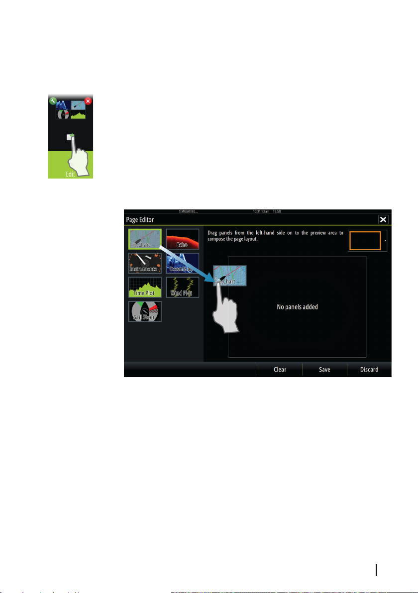
1. Select the New icon in the favorite panel on the Home page to
open the page editor dialog
2. Drag and drop page icons to set up a new page
Note: 5" unit favorite pages can have a maximum of 2
Ú
applications.
3. Change the panel arrangement (only possible for 2 or 3 panels),
if required
4. Save the page layout.
The system displays the new favorite page, and the new page is
included in the list of favorite pages on the Home page.
Creating a Man Overboard waypoint
If an emergency situation should occur, you can create a Man
Overboard (MOB) waypoint at the vessel’s current position by
selecting the MOB button on the Home page.
When you activate the MOB function the following actions are
automatically performed:
• a MOB waypoint is created at the vessel’s position
• the display switches to a zoomed chart panel, centered on the
vessel's position
Basic operation | Vulcan Series Getting Started
11
Page 12

• the system displays navigation information back to the MOB
waypoint
Multiple MOB waypoints are saved by repeatedly pressing the MOB
buttons. The vessel continues to show navigation information to
the initial MOB waypoint. Navigation to subsequent MOB waypoints
needs to be done manually.
Delete a MOB waypoint
1. Select the MOB waypoint to activate it
2. Select the MOB waypoint's pop-up to display the MOB waypoint
dialog
3. Select the delete option in the dialog.
A MOB waypoint can also be deleted from the menu when it is
activated.
12
Basic operation | Vulcan Series Getting Started
Page 13
3
Charts
The chart function displays your vessel’s position relative to land
and other chart objects. On the chart panel you can plan and
navigate routes, place waypoints, and display AIS targets.
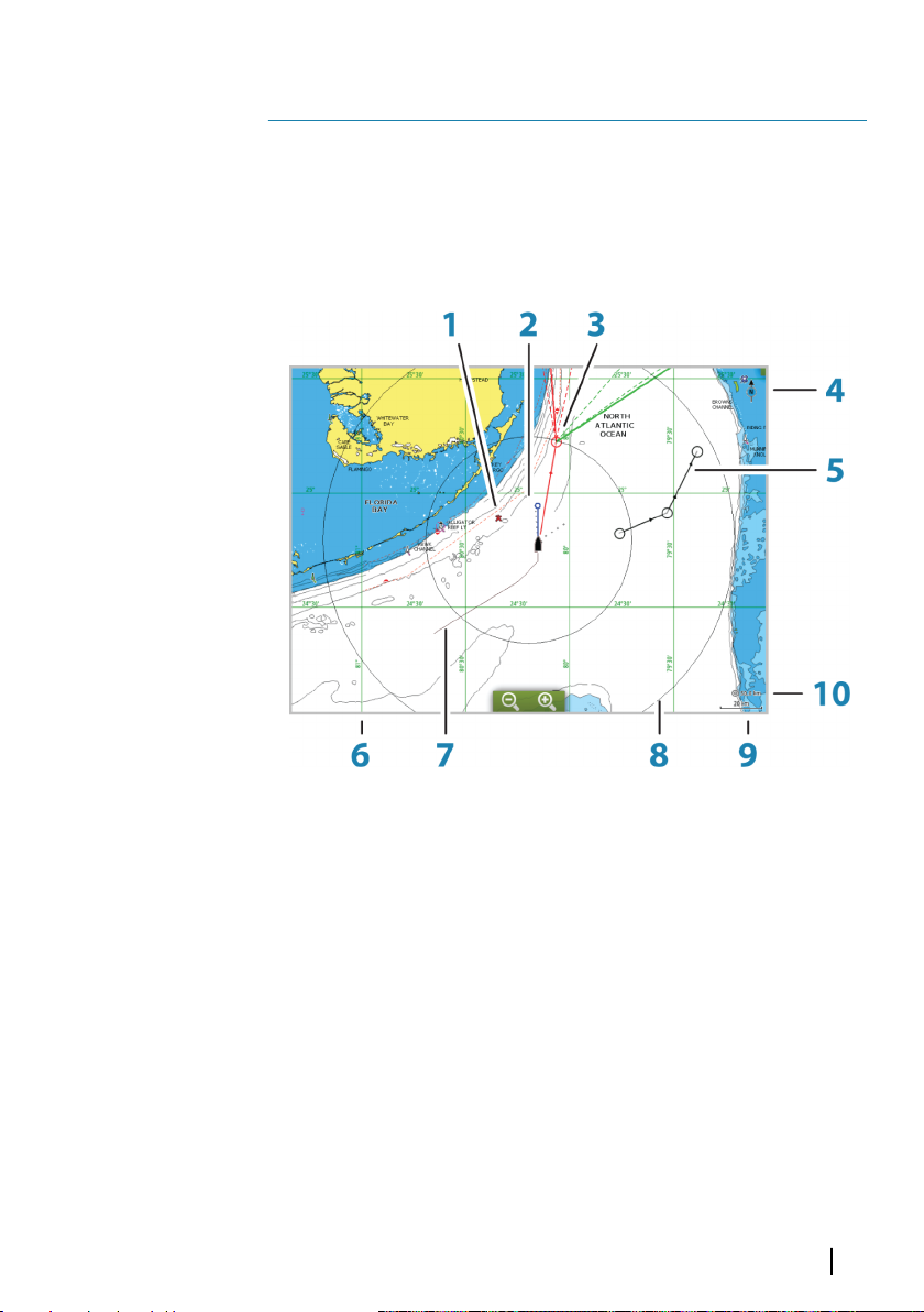
The Chart panel
1 MOB (Man Over Board) mark
2 Vessel with extension line (extension line is optional)
3 Waypoint with Laylines*
4 North indicator
5 Route*
6 Grid lines*
7 Track*
8 Range rings*
9 Chart range scale
10 Range rings interval (only displayed when Range rings are
turned on)
Charts | Vulcan Series Getting Started
13
Page 14
* Optional chart items. You turn the optional chart items on/off
individually from the Chart settings dialog.
Showing dual chart types
If you have different chart types available - embedded or in the card
slot - you can show two different chart types simultaneously on a
page with two chart panels.
You can select a dual chart panel by pressing and holding the Chart
application button on the Home page, or by creating a favorite
page with two chart panels.
Panning the chart
You can move the chart in any direction by dragging your finger on
the screen.
Select the Clear cursor menu option to remove the cursor and
cursor window from the panel. This also centers the chart to the
vessel position.
Using the cursor on the panel
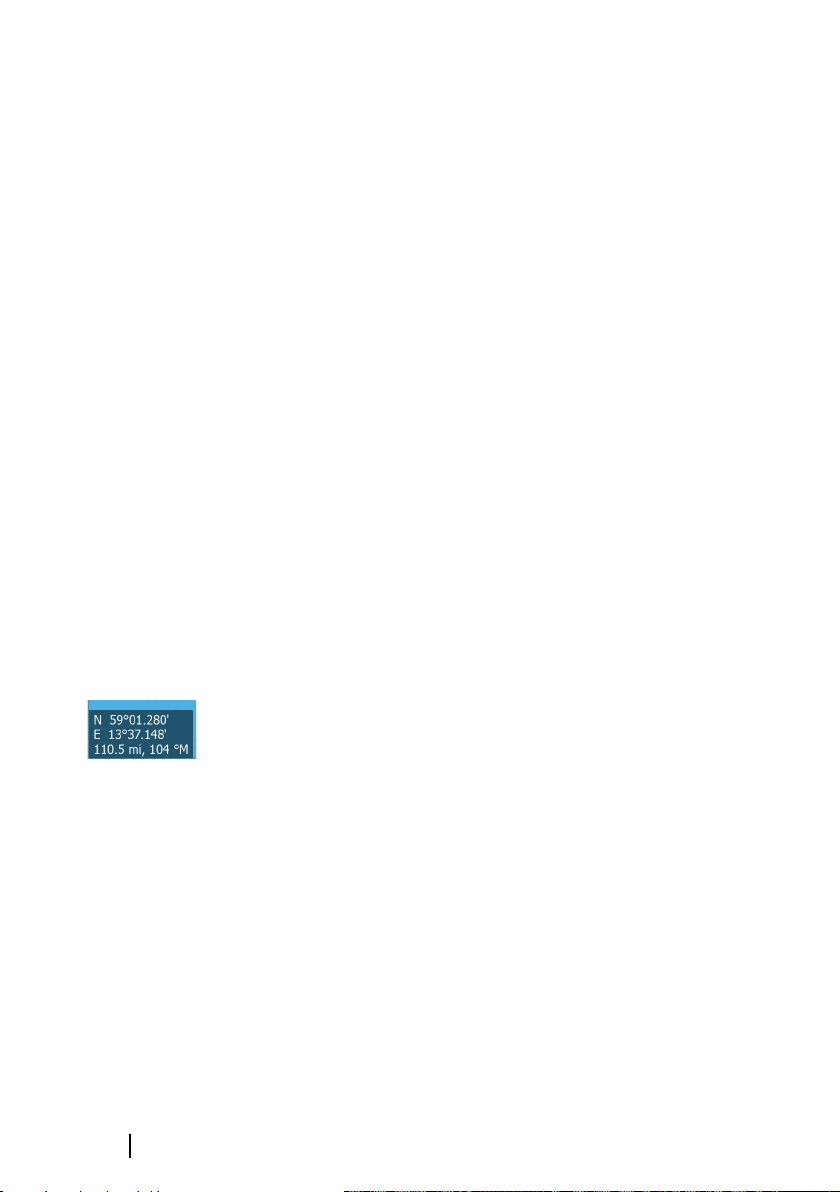
The cursor can be used to measure a distance, to mark a position,
and to select items.
By default, the cursor is not shown on the panel.
Position the cursor by tapping the desired location on the screen.
When the cursor is active, the cursor position window is displayed.
To remove the cursor and cursor elements from the panel, select
the Clear cursor option.
14
GoTo cursor
You can navigate to a selected position on the image by positioning
the cursor on the panel, then using the Goto Cursor option in the
menu.
The Cursor assist function
The cursor assist function allows for fine tuning and precision
placement of the cursor without covering details with your finger.
Press and hold your finger on the screen to switch the cursor
symbol to a selection circle, appearing above your finger.
Charts | Vulcan Series Getting Started
Page 15
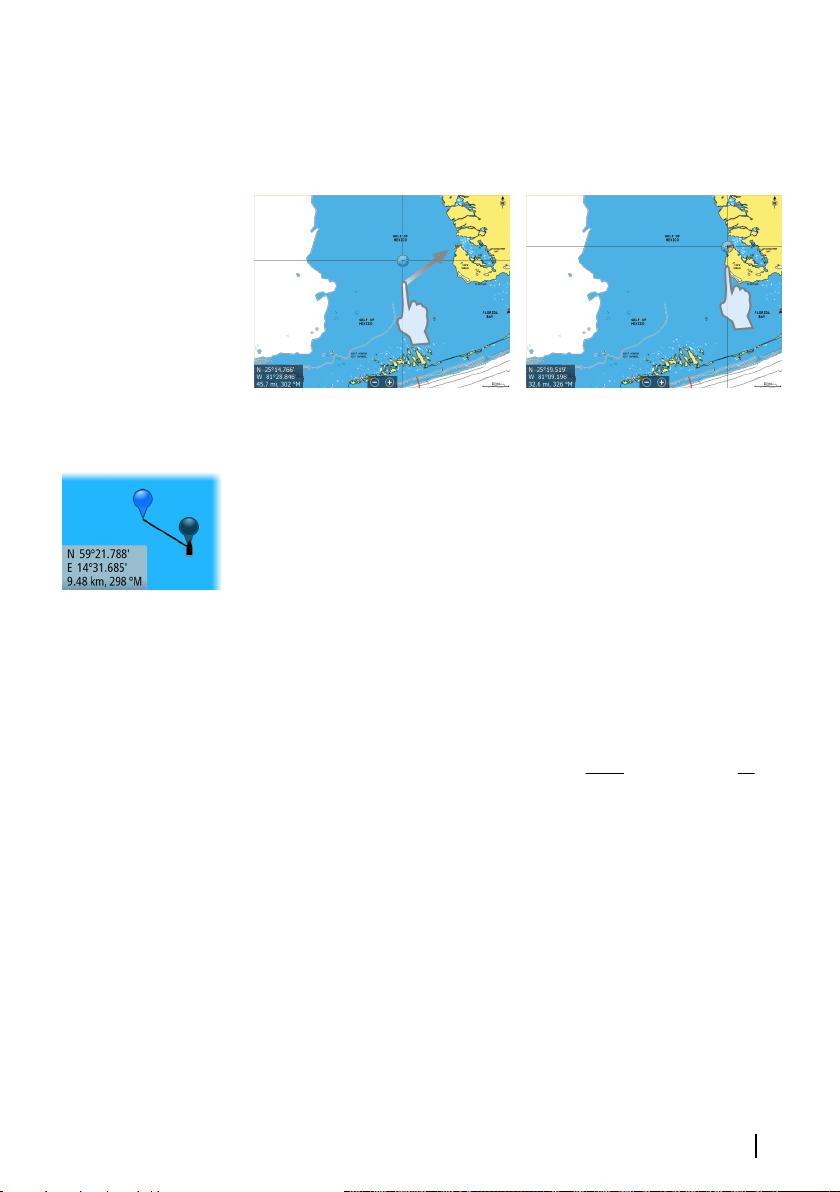
Without removing your finger from the screen, drag the selection
circle over the desired item to display item information.
When you remove your finger from the screen the cursor reverts to
normal cursor operation.
Measuring distance
The cursor can be used to measure the distance between your
vessel and a selected position, or between 2 points on the chart
panel.
1. Position the cursor on the point from where you want to
measure the distance. Start the measure function from the
menu
- The measuring icons appear with a line drawn from the vessel
center to the cursor position, and the distance is listed in the
cursor information window.
2. You can reposition the measuring points by dragging either
icon as long as the measuring function is active
Note: The bearing is always measured from the grey icon to the
Ú
blue icon.
You can also start the measuring function without an active cursor.
Both measuring icons are then initially located at the vessel position.
The grey icon follows the vessel as the vessel moves, while the blue
icon remains at the position given when you activated the function.
You terminate the measuring function by selecting the Finish
measuring menu option.
Positioning the vessel on the chart panel
Charts | Vulcan Series Getting Started
15
Page 16
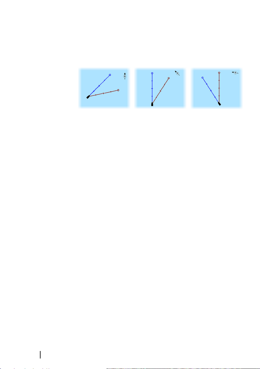
Chart orientation
Several options are available for how the chart is rotated in the
panel. The chart orientation symbol in the panel’s upper right
corner indicates the north direction.
North up Heading up
North up
Displays the chart with north upward.
Heading up
Displays the chart with the vessel’s heading directed upward.
Heading information is received from a compass. If heading is not
available, then the COG from the GPS is used.
Course up
Displays the chart with the direction the vessel is ACTUALLY
traveling directed upward, which in some cases is not the direction
the vessel is headed.
Course up
Look ahead
Moves the vessel icon closer to the bottom of the screen so that
you can maximize your view ahead.
Displaying information about chart items
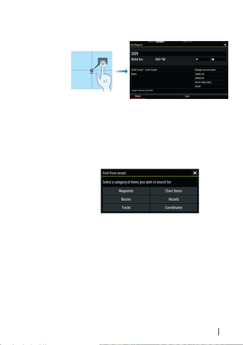
When you select a chart item, a waypoint, a route, or a target, basic
information for the selected item is displayed. Select the chart item's
pop-up to display all available information for that item. You can
also activate the detailed information dialog from the menu.
16
Note: If you are viewing applicable C-MAP charts on your
Ú
system, you can select marine objects to display information
about services and available multimedia (photos) associated
with the location or object.
Charts | Vulcan Series Getting Started
Page 17
Note: Pop-up information has to be enabled in chart settings to
Ú
see basic item information.
Find objects on chart panels
You can search for other vessels or various chart items from a chart
panel.
Activate the cursor on the panel to search from the cursor position.
If the cursor is not active, the system searches for items from the
vessel's position.
Note: You must have a SIRIUS data package subscription to
Ú
search for fueling stations and an AIS receiver connected to
search for vessels. SIRIUS is not available on 5" and 7" units.
3D charts
The 3D option provides a three dimensional graphical view of land
and sea contours.
Note: All chart types work in 3D mode, but without 3D
Ú
cartography for the appropriate area the chart appears flat.
When 3D chart option is selected, the Pan and the Rotate icons
appear on the right side of the chart panel.
Charts | Vulcan Series Getting Started
17
Page 18
4
Waypoints, Routes, and Tracks
Waypoints
A waypoint is a user generated mark positioned on a chart, or on
the Echosounder image. Each waypoint has an exact position with
latitude and longitude coordinates. A waypoint positioned on the
Echosounder image has a depth value, in addition to position
information. A waypoint is used to mark a position you later may
want to return to. Two or more waypoints can also be combined to
create a route.
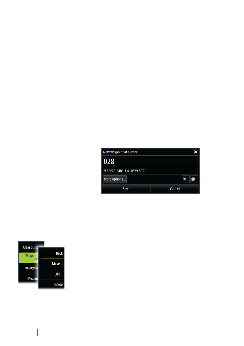
Saving waypoints
You can save a waypoint at a selected location by positioning the
cursor on the panel, and then selecting the new waypoint option in
the menu.
18
In the Chart and Nav panels, you can save a waypoint at the vessel
position, when the cursor is not active, by selecting the new
waypoint option in the menu.
Moving a waypoint
1. Select the waypoint you want to move. The waypoint icon
expands to indicate that it is active.
2. Activate the menu and select the waypoint in the menu
3. Select the move option
4. Select the new waypoint position
5. Select Finish in the menu.
The waypoint is now automatically saved at the new position.
Waypoints, Routes, and Tracks | Vulcan Series Getting
Started
Page 19
Edit a waypoint
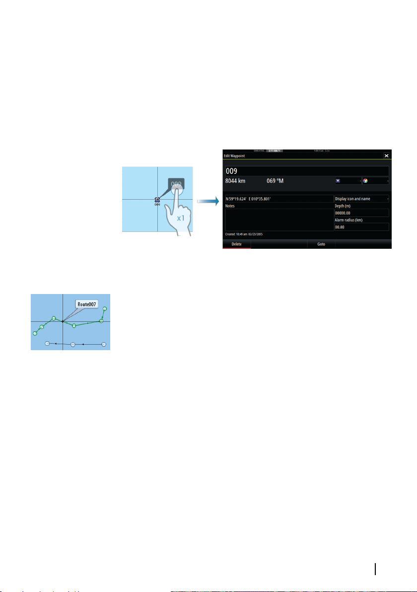
You can edit all information about a waypoint from the Edit
Waypoint dialog.
This dialog is activated by selecting the waypoint's pop-up, or from
the menu when the waypoint is activated.
The dialog can also be accessed from the Waypoints tool on the
Home page.
Routes
A route consists of a series of routepoints entered in the order that
you want to navigate them.
When you select a route on the chart panel it turns green, and the
route name is displayed.
The system includes support for Navionics Autorouting and C-MAP
Easy Routing. This feature automatically suggests routepoints
between the first and last routepoint of a route, or between
selected routepoints in a complex route. You can use the feature
when you create a new route, or you can use it to edit already saved
routes.
Creating a new route on the chart panel
1. Activate the cursor on the chart panel
2. Select the new route option from the menu
3. Position the first waypoint on the chart panel
4. Continue positioning new routepoints on the chart panel until
the route is completed
5. Save the route by selecting the save option in the menu.
Waypoints, Routes, and Tracks | Vulcan Series Getting Started
19
Page 20
Edit a route from the chart panel
1. Select the route to make it active
2. Select the route edit option in the menu
3. Position the new routepoint on the chart panel:
- If you set the new routepoint on a leg, a new point is added
between existing routepoints
- If you set the new routepoint outside the route, the new
routepoint is added after the last point in the route
4. Drag a routepoint to move it to a new position
5. Save the route by selecting the save option in the menu.
Note: The menu changes depending on the selected edit
Ú
option. All edits are confirmed or cancelled from the menu.
Tracks
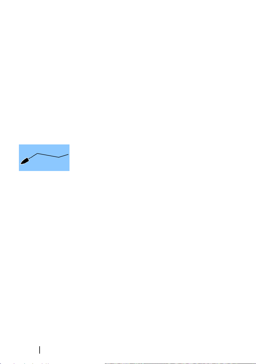
Tracks are a graphical presentation of the historical path of the
vessel, allowing you to retrace where you have travelled. Tracks can
be converted to routes from the Edit dialog.
From the factory, the system is set to automatically track and draw
the vessel's movement on the chart panel. The system continues to
record the Tracks until the length reaches the maximum points, and
then automatically begins overwriting the oldest points.
The automatic tracking function can be turned off from the Tracks
dialog.
20
Creating new Tracks
You can start a new track from the Tracks dialog, activated by using
the Tracks tool on the Home page.
Waypoints, Routes, and Tracks | Vulcan Series Getting
Started
Page 21

5
Navigating
The navigation function included in the system allows you to
navigate to the cursor position, to a waypoint, or along a predefined
route.
If autopilot functionality is included in your system, the autopilot
can be set to automatically navigate the vessel.
For information about positioning waypoints and creating routes,
refer to "Waypoints, Routes, and Tracks" on page 18.
Navigate to cursor position
You can start navigating to a cursor position on any chart, or
Echosounder panel.
Position the cursor at the selected destination on the panel, and
then select the Goto Cursor option in the menu.
Note: The Goto Cursor menu option is not available if you are
Ú
already navigating.
Navigate a route
You can start navigating a route from the chart panel or from the
Route dialog.
When route navigation is started, the menu expands and shows
options for canceling the navigation, for skipping a waypoint, and
for restarting the route from current vessel position.
Navigating with the autopilot
When you start navigation on a system with autopilot functionality,
you are prompted to set the autopilot to navigation mode.
If you choose not to engage the autopilot, the autopilot can be set
to navigation mode from the Autopilot Controller later on.
For more information about autopilot functionality, refer to "Autopilot"
on page 26.
Navigating | Vulcan Series Getting Started
21
Page 22
6
SailSteer panel
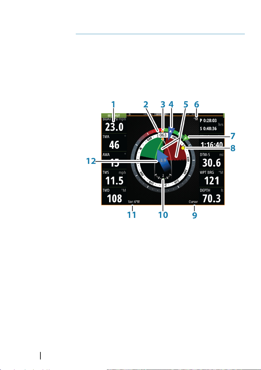
The SailSteer panel provides a composite view of key sailing data. All
data is displayed relative to the yacht’s bow, providing a clear and
easy to understand image of important sailing data.
The SailSteer panel can be shown as a full screen panel, or in a
multi-panel page.
The number of data fields included in the panel is dependent on
available panel size.
22
1 User configurable data fields
2 Vessel heading
3 COG (Course Over Ground)
4 Apparent wind*
5 Port and starboard laylines.
6 Magnetic or True reference
7 TWA (True Wind Angle) - Green if on TWA upwind or
downwind. Blue if off target by 10º or more, or on a free
leg. The indicator will fade from blue to green the closer
you get to the exact angle.*
8 Bearing to current waypoint
SailSteer panel | Vulcan Series Getting Started
Page 23

9 Active (next) waypoint ID, routepoint ID, or cursor
10 Rudder angle
11 Magnetic variation
12 Tide rate and relative direction*
* Optional images. You can turn the optional images on/off from
the menu.
Selecting data fields for the SailSteer panel
Data sources connected to the system can be viewed on the
SailSteer panel.
1. Select the SailSteer panel to make it active.
2. Select the MENU button and select the edit option.
- Edit mode is indicated in top of the panel.
3. Select the instrument field you want to change.
- The selected field has a highlighted frame.
4. Select the MENU button again to select info.
5. Repeat the steps to change other instrument fields.
6. Save your settings by selecting the save option in the menu.
Sail Time calculations
The system calculates the time and distance to a waypoint taking
into consideration that the vessel is sailing on a layline course to the
waypoint. Data showing time calculations will be indicated with an S extension:
DTW-S Sailing Distance to Waypoint
TTW-S Sailing Time to Waypoint
ETA-S Sailing Estimated Time of Arrival
SailSteer panel | Vulcan Series Getting Started
23
Page 24
7
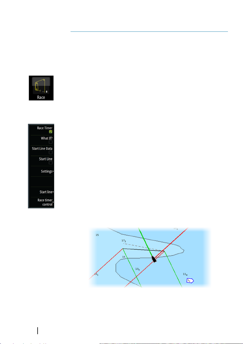
Race panel
Use the Race panel to:
• Display and control the race timer
• Create and manage the race start line
• Display race start line data
• Display the race start line in a chart diagram on the Race panel
Select the Race button on the Home page to display the Race panel.
Display options
Use the Race panel menu to specify if you want to display the Race
Timer, What if? data, Start Line Data, or Start Line display (display the
boat and start line in graphical format).
Start Line on Chart panel
You can display a race start line overlaid on the Chart panel. The
start line data can be displayed in the Instrument page. If you have
an H5000 CPU on your network, start line data is calculated by the
H5000 CPU. Otherwise the data is calculated in the MFD.
Viewing the start line on the chart panel allows the navigator to
assess around the starting area for hazards. Use the laylines to see
where the likely tracks into and out of the starting area will be
relative to the chart data.
The solid black line indicates the start line (between the two starting
marks) on the chart panel. You can switch off the start line overlaid
on the Chart if desired.
24
Race panel| Vulcan Series Getting Started
Page 25
Time and Wind plots
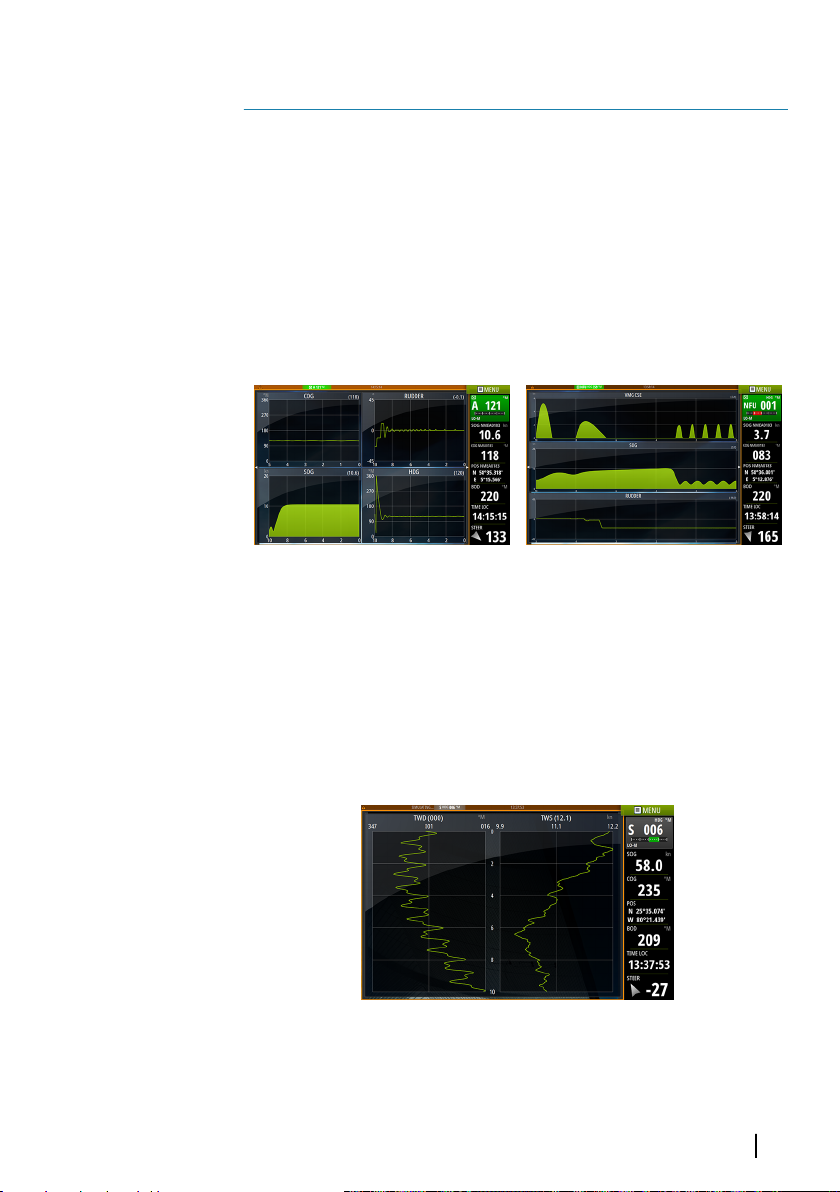
The system can present data history in different plots. The plots can
be displayed in full page, or combined with other panels.
8
The Time plot panel
The Time plot panel consists of two predefined layouts. You switch
between the layouts by selecting the left and right panel arrows.
You can also select the layout from the menu.
You can select which data to present on a time plot panel, and you
can define the time range for each plot.
Layout 1 Layout 2
Wind Plot panel
A Wind Plot is a special type of Time Plot specifically designed to
help you understand recent changes in wind speed and direction.
The Wind Plot panel includes wind direction and wind speed. The
graphics are configured vertically with the newest data being
displayed at the top of the screen.
Time and Wind plots| Vulcan Series Getting Started
25
Page 26
9
Autopilot
If a compatible autopilot computer is connected to the system,
autopilot functionality is available in the system.
The system does not allow for more than one autopilot computer
on the network.
The display unit automatically detects the autopilot computer
available on the network and presents settings, configuration and
user options for the connected computer.
For details about installing and configuring an autopilot computer,
refer to the separate manuals that come with the autopilot
computer.
Safe operation with the autopilot
Warning: An autopilot is a useful navigational aid,
but DOES NOT replace a human navigator.
Warning: A physical standby key should be available
for the autopilot.
26
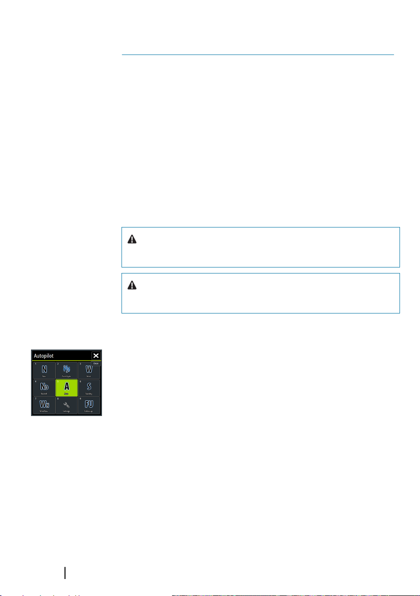
Activating the autopilot
You activate the autopilot from any panel by selecting the autopilot
tile in the Instrument bar, followed by selecting a mode in the
Autopilot Controller.
Switching from automatic mode to manual steering
You switch the autopilot to STBY mode from any automatic
operation mode from the autopilot pop-up or using a physical
standby key.
Autopilot| Vulcan Series Getting Started
Page 27
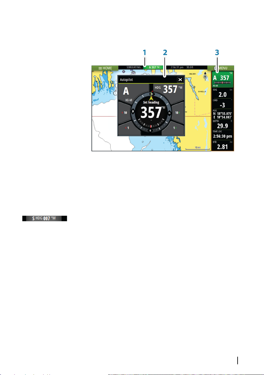
Autopilot indication on the pages
1 Autopilot indication in Status bar
2 Autopilot pop-up
3 Autopilot tile in Instrument bar
Autopilot mode indication in the Status bar
The Status bar shows autopilot information as long as an autopilot
computer is connected to the network.
Icons are included if the autopilot is passive or locked by another
autopilot control unit.
Autopilot pop up
You control the autopilot from the autopilot pop-up. The pop-up
has a fixed position on the page, and it is available for all pages
except when an Autopilot panel is active.
As long as the autopilot pop-up is active, you cannot operate the
background panel or its menu. You remove the pop-up from a page
by selecting the X in the upper right corner. You turn it on again by
selecting the autopilot tile in the instrument bar.
The following pop-ups are available:
Autopilot| Vulcan Series Getting Started
27
Page 28
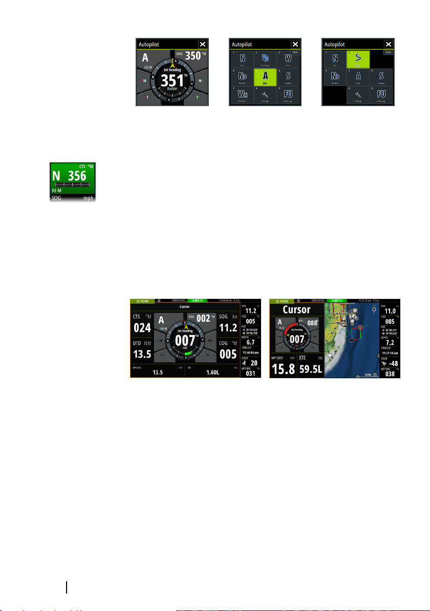
Autopilot controller Mode selection Turn pattern selection
Autopilot tile in Instrument bar
You can select to show the autopilot tile in the Instrument bar.
If the autopilot pop-up is turned off you can turn it on by selecting
the tile in the Instrument bar.
The Autopilot panel
The autopilot panel is used to display navigation data. It can be
shown as a full screen panel, or in a multi-panel page.
The number of data fields included in the autopilot panel is
dependent on available panel size.
28
Autopilot| Vulcan Series Getting Started
Page 29
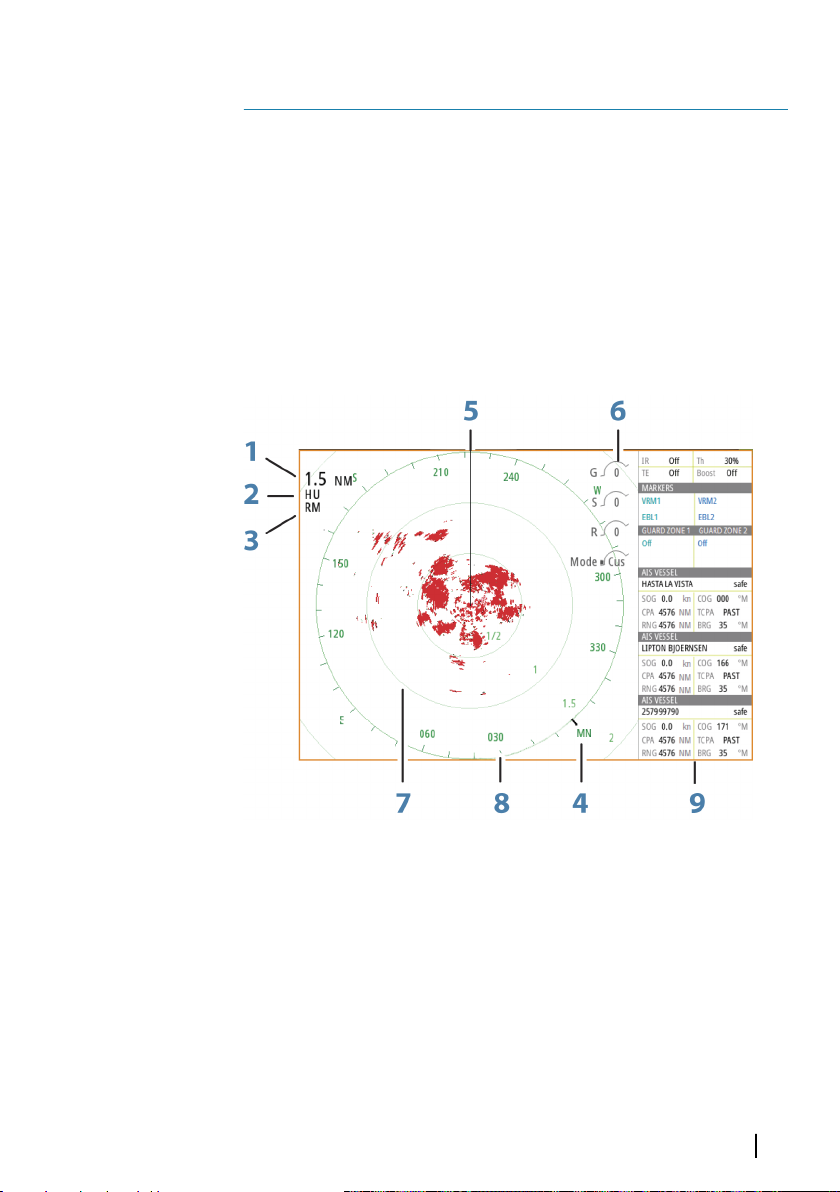
Radar
Radar is not available on the 5" and 7" units.
The radar panel can be set up as a full screen view or combined
10
with other panels.
Using the chart menu, the radar image can also be displayed as an
overlay on a chart panel.
Ú
The radar panel
Note: Radar overlay requires data from a heading sensor or
compass to ensure proper orientation with the chart.
1 Range
2 Orientation
3 Motion
4 Compass*
5 Heading line*
6 Rotary controls
7 Range rings*
Radar| Vulcan Series Getting Started
29
Page 30

8 Range markers*
9 Data bar
* Optional radar symbology.
Radar symbology can be turned ON/OFF collectively from the Radar
menu, or individually as described in "Radar settings panel" on page 31.
Radar menu options
Use the Radar menu to set up EBL/VRM, guard zones, set the radar
in standby and access the Adjust, Advanced and View options.
• EBL/VRM - The electronic bearing line (EBL) and variable range
marker (VRM) allows quick measurements of range and bearing
to vessels and landmasses within radar range.
• Guard zones - A guard zone is an area (either circular or a sector)
that you can define on the radar image. When activated, an alarm
alerts you when a radar target enters or exits the zone.
• Standby - The power to the radar scanner is on, but the radar is
not transmitting.
Adjust the radar image
From the radar menu use the Adjust options to set the mode, gain,
Sea clutter and Rain clutter. By adjusting these settings, you may be
able to improve the radar image by adjusting the radar sensitivity,
and by filtering out the random echoes from sea and weather
conditions.
30
Radar| Vulcan Series Getting Started
Page 31
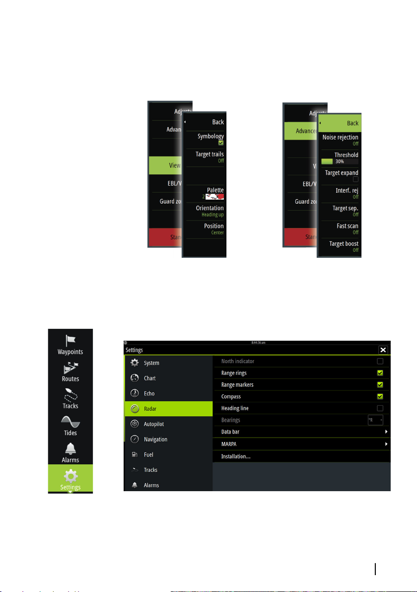
View and Advanced options
Use the menu View and Advanced options to refine the radar image
to meet your needs.
View menu Advanced menu
Radar settings
Radar| Vulcan Series Getting Started
31
Page 32
Echosounder
The Echosounder function provides a view of the water and bottom
beneath your vessel, allowing you to detect fish and examine the
structure of the sea floor.
11
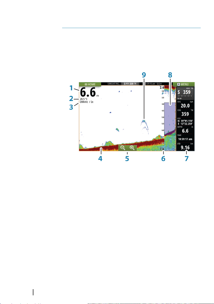
The Echosounder image
32
1 Depth
2 Temperature
3 Frequency and Zoom scale
4 Bottom
5 Zoom buttons
6 Depth range scale
7 Instrument panel
8 Zoom column
9 Fish arches
Echosounder| Vulcan Series Getting Started
Page 33
Viewing Echosounder history
You can view echosounder history by panning the image. To
resume normal scrolling, select the Clear cursor menu option.
Setting up the image
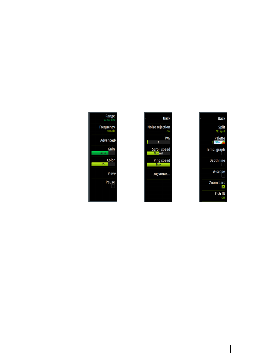
Use the Echosounder menu options to set up the image. When the
cursor is active, some options on the Echosounder menu are
replaced with cursor mode features. Select Clear cursor to return
to the normal Echosounder menu.
Main menu
Note: The A-scope and Zoom bars options are not available on
Ú
the 5" units.
Echosounder| Vulcan Series Getting Started
Advanced menu
View menu
33
Page 34
StructureScan
StructureScan HD uses high frequencies to provide a high
resolution, picture-like image of the seabed.
12
The StructureScan image
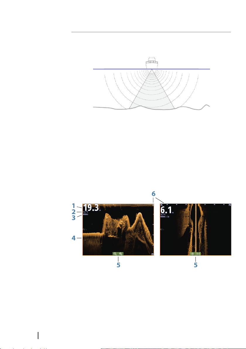
The view
The StructureScan panel can be set up as a DownScan image, or
showing left/right side scanning.
The DownScan image can also be added as an overlay to the
traditional Echosounder image.
34
1 Depth
2 Temperature
3 Frequency
4 Bottom
StructureScan| Vulcan Series Getting Started
Page 35
5 Zoom (downscan) / Range (sidescan) icons
6 Range scale
Setting up the image
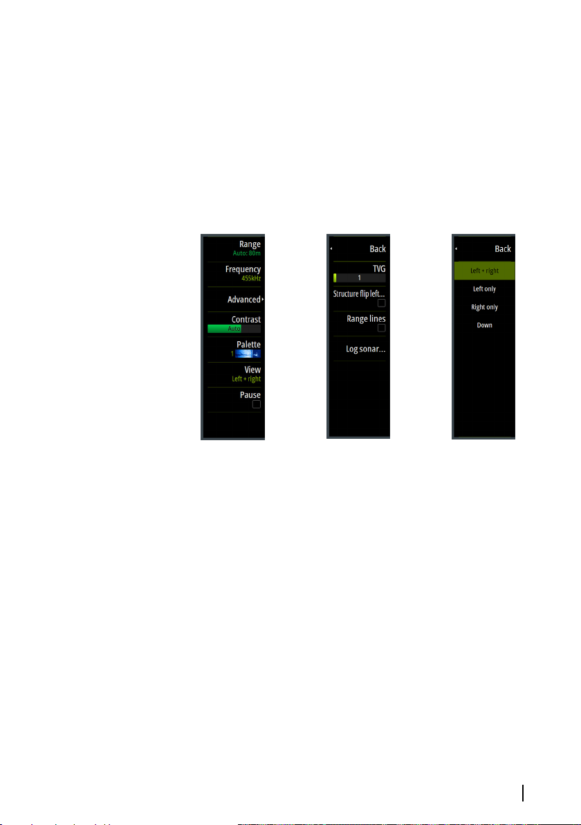
Use the StructureScan menu options to set up the image. When the
cursor is active, some options on the StructureScan menu are
replaced with cursor mode features. Select Clear cursor to return
to the normal StructureScan menu.
Main menu
StructureScan| Vulcan Series Getting Started
Advanced menu
View menu
35
Page 36
ForwardScan
ForwardScan sonar is a navigational aid that helps you monitor the
underwater environment in front of your vessel while carrying out
slow speed maneuvers.
13
To use the ForwardScan feature you must have a ForwardScan
transducer mounted on your vessel. For installation instructions,
refer to the ForwardScan transducer installation manual.
Ú
Ú
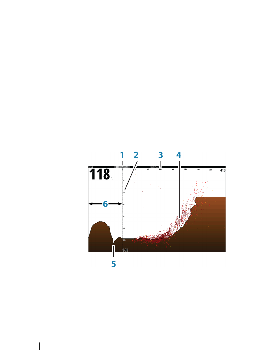
The ForwardScan image
Note: Do not rely on this equipment as your principle source of
navigation or hazard detection.
Note: Do not use this equipment to gauge depth or other
conditions for swimming or diving.
36
1 Transducer location shown as the origin on the page
2 Depth range scale and vessel position
3 Forward range scale
4 Point data
ForwardScan| Vulcan Series Getting Started
Page 37
5 Bottom
6 Depth history
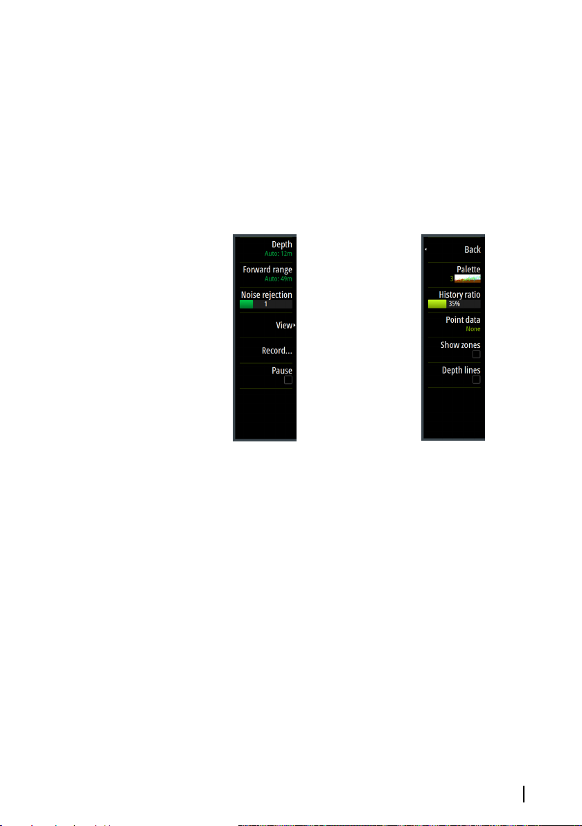
Setting up the image
Use the ForwardScan menu options to set up the image. When the
cursor is active, some options on the ForwardScan menu are
replaced with cursor mode features. Select Clear cursor to return
to the normal ForwardScan menu.
Main menu
View menu
Heading extension
You can use the heading extension to monitor ForwardScan on the
chart panel. Heading extension colors are based on the
ForwardScan alarm values.
ForwardScan| Vulcan Series Getting Started
37
Page 38
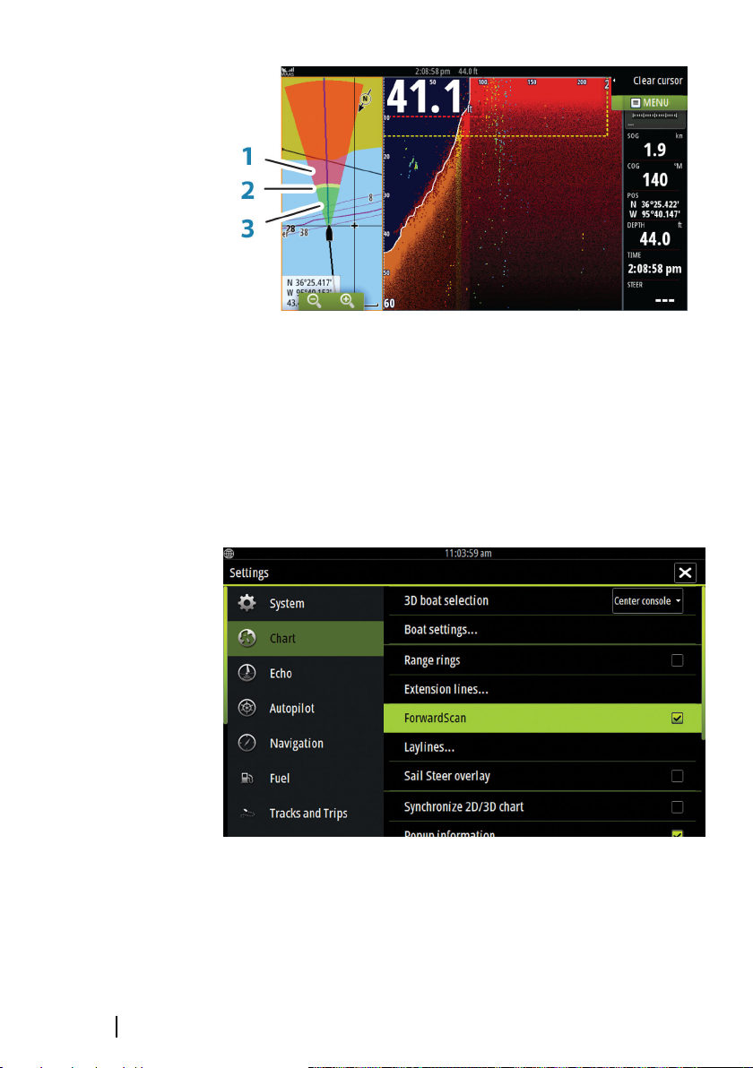
ForwardScan extension
1 Red - Critical
2 Yellow - Warning
3 Green - Safe
Select ForwardScan in the Chart Settings dialog to view the
ForwardScan heading extension on the chart panel.
38
ForwardScan| Vulcan Series Getting Started
Page 39
Instrument panels
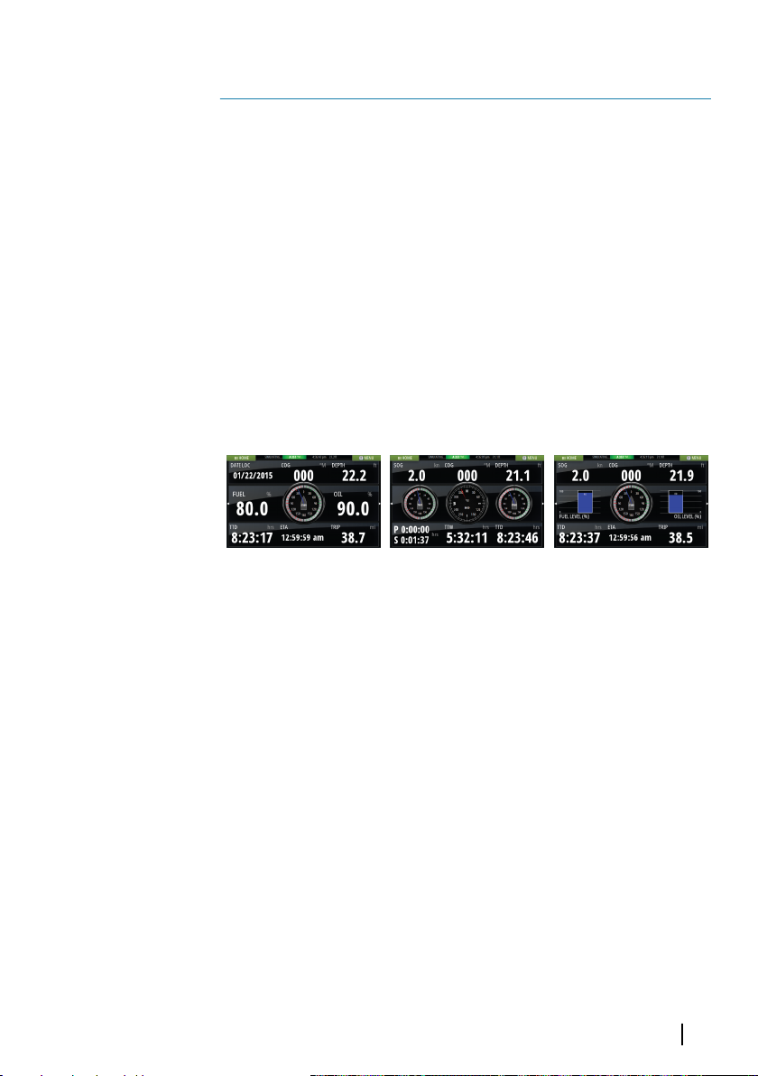
The Instruments panels consist of multiple gauges - analog, digital
and bar - that can be customized to display selected data. The
Instruments panel displays data on dashboards, and you can define
14
up to ten dashboards within the Instruments panel.
Ú
Dashboards
A set of dashboard styles are predefined to display vessel,
navigation, and angler information.
You switch between the panel’s dashboards by selecting the left
and right arrow buttons on the panel. You can also select the
dashboard from the menu.
Note: To include fuel/engine information, engine and tank
information has to be configured from the Settings panel.
Vessel dashboard Navigation dashboard Angler dashboard
Note: Additional dashboards can be activated from the menu if
Ú
other systems (e.g. CZone) are present on the network.
Instrument panels| Vulcan Series Getting Started
39
Page 40
Wireless connection
GoFree wireless connectivity gives you the ability to:
• Use a wireless device to remotely view (smartphone and tablet)
15
• Access the GoFree Shop.
• Upload your Sonar logs to create custom maps at Insight
• Download software updates
• Connect to third party applications
The unit includes Built-in wireless functionality for connecting to the
internet and wireless devices such as smartphones and tablets.
Ú
Connect and disconnect from a wireless hotspot
To connect to a wireless hotspot, select the Wireless option in the
System Controls dialog and then select Not Connected. This opens
the Wireless Devices dialog. Use this dialog to select the desired
hotspot, enter the login information and then select Connect.
Connecting to a wireless hotspot changes the wireless mode to
Client mode. In this mode, you can access the GoFree Shop.
To disconnect from a wireless hotspot, select the Wireless option in
the System Controls dialog, then select Connected hotspot_name, and
then Disconnect. This changes the wireless mode to Access point
mode. In this mode, you can connect a wireless device so that Apps
such as GoFree Controller & Viewer can access the vessel's
navigation information.
and control the system (tablet only).
Genesis.
Note: Maps, charts, software updates, and other data files can
be large. Your internet service provider may charge you based
on the amount of data you transfer. If you are unsure, contact
your service provider to confirm rates and restrictions.
40
Wireless connection| Vulcan Series Getting Started
Page 41
Audio
If a SonicHub server, a FUSION marine entertainment system, or
NMEA 2000 audio system is connected to the NMEA 2000 network,
you can use the Vulcan to control and customize the audio system
16
on your vessel.
You can connect a SiriusXM radio/tuner to your FUSION server to
receive SiriusXM radio on your system. The SiriusXM channels
available vary depending on your selected subscription package.
SiriusXM radio is only available in certain locations. For more
information refer to www.siriusXM.com. SiriusXM audio is not
available on 5" and 7" units.
Before you can start using your audio equipment, it must be
installed according to the Vulcan Installation manual and to the
documentation included with the audio device.
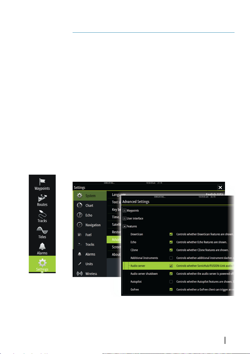
Enabling audio
A compatible audio device connected to the NMEA 2000 network
should automatically be identified by the system. If not, enable the
feature from the Advanced Settings dialog.
Audio| Vulcan Series Getting Started
41
Page 42
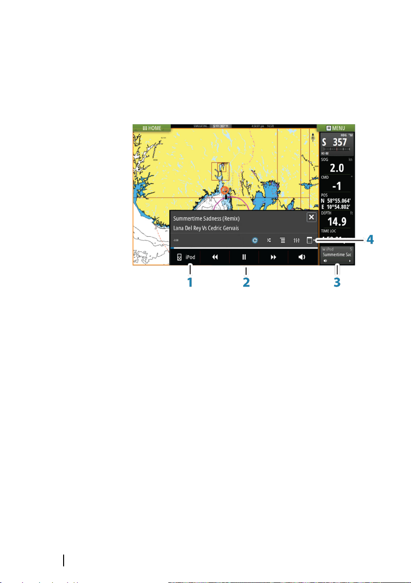
The Audio panel
You activate the audio panel by activating the audio tile in the
Instrument bar.
The control buttons, tools and options vary from one audio source
to another as described later in this chapter.
1 Audio source
2 Audio control buttons
3 Audio tile
4 Audio tools
42
Operating the audio system
1. Select the Audio tile in the Instrument bar to activate the Audio
overlay.
2. Select the options icon and then select the audio server.
3. Select the source icon and then select the audio source.
- Number of sources depends on the active audio server.
4. Use the panel buttons to control your audio system.
For available options, refer to the documentation following your
audio equipment.
Audio| Vulcan Series Getting Started
Page 43
Alarms
Alarm system
17
The system continuously checks for dangerous situations and
system faults while the system is running. When an alarm situation
occurs, an alarm message pops up on the screen.
If you have enabled the siren, the alarm message is followed by an
audible alarm, and the switch for external alarm becomes active.
The alarm is recorded in the alarm listing so that you can see the
details and take the appropriate corrective action.
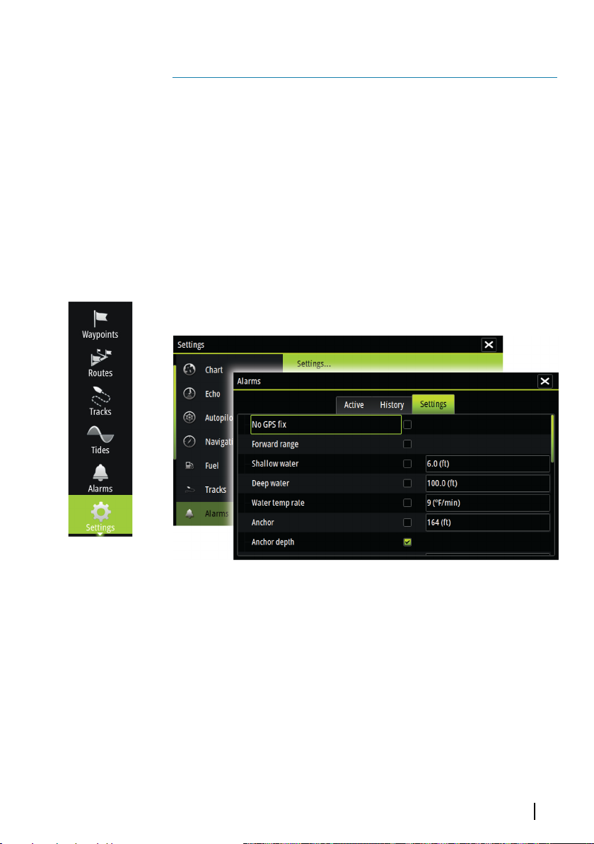
Alarms dialog
All alarms are setup in the Alarms Settings dialog.
Alarms| Vulcan Series Getting Started
43
Page 44
Tools
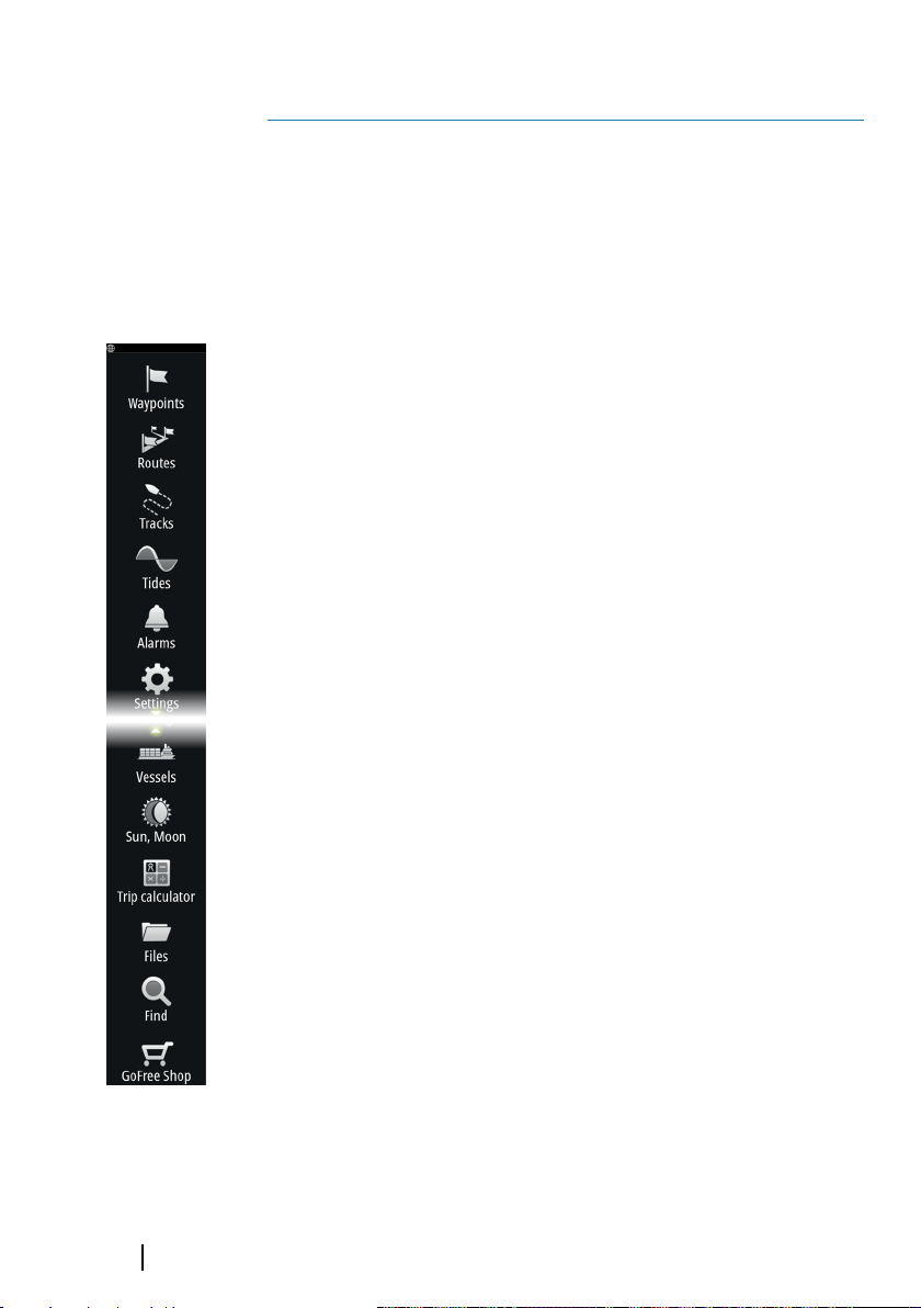
By default, the Tools panel includes icons used for accessing options
and tools that are not specific to any panel.
18
When external equipment is integrated to the unit, new icons might
be added to the Tools panel. These icons are used for accessing the
external equipment's features.
Waypoints/routes/tracks
List of waypoints, routes, and tracks with details.
Select the waypoint, route, or track you wish to edit or delete.
Tides
Displays tide information for the tide station nearest to your vessel.
Select the arrow panel buttons to change the date, or select the
date field to access the calendar function.
Available tide stations can be selected from the menu.
Alarms
Active alarms
List of active alarms.
44
Alarm history
List of all alarms with time stamp.
Alarm settings
List of all available alarm options in the system, with current
settings.
Settings
Provides access to application and system settings.
Vessels
Status listing
List of all AIS and DSC vessels with available information.
Tools| Vulcan Series Getting Started
Page 45

Message listing
List of all messages received from other AIS vessels with time stamp.
Sun, Moon
Displays sunrise, sunset, moonrise and moonset for a position based
on entered date and the position’s latitude/longitude.
Trip calculator
Trip 1 / Trip 2
Displays voyage and engine information, with reset option for all
data fields.
Today
Displays voyage and engine information for current date. All data
fields are automatically reset when the date changes.
Files
File management system for Files, Waypoints, Routes, Trails, and
Settings.
To view files, select a file in the Files panel and then the view file
option in the Details dialog. You can copy screen captures and logs
to a card in the card reader.
You can also export System Settings, Waypoints, Routes, and Trails
to a memory card.
To view recorded sonar logs, use the view sonar log option in the
Sonar settings dialog.
Find
Search function for chart items (waypoints, routes, tracks, etc.).
GoFree Shop
Note: The built-in wireless functionality must be connected to
Ú
an external wireless hotspot in order to access the GoFree Shop.
Refer to "Connect and disconnect from a wireless hotspot" on page 40.
Opens the GoFree Shop web site. At the GoFree Shop you can
browse, purchase, and download compatible charts for your system.
You can also upload your Echosounder logs to be shared on Social
Tools| Vulcan Series Getting Started
45
Page 46

Map charts. When you log on, the system automatically gives you a
notification if a new software version is available for your system. If
an update is available, you can download it to a card slot or defer
the download until later.
46
Tools| Vulcan Series Getting Started
Page 47

Page 48

*988-11123-002*
0980
 Loading...