

Page 1
NATIONAL
SmartVap
TM
REFRIGERATION
PROGRAM SPECIFICATIONS
AND OPERATING
INSTRUCTIONS
1079817
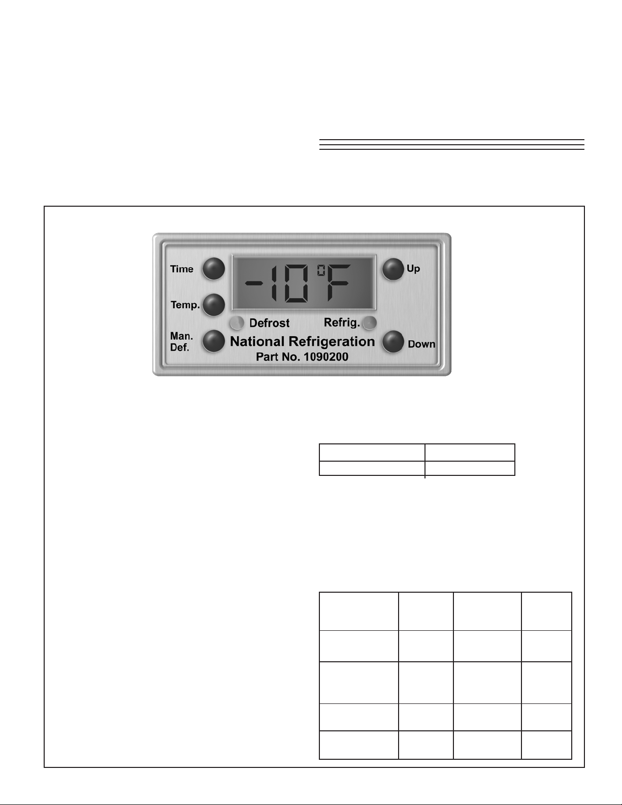
Electronic Room Thermostat & Defrost Control
Electronically
Controlled System
Model: (Part # 1090200)
Electrical Power: 115/1/60, 208-230/1/60
Factory Settings:
This Defrost/Temperature control has been
COMPLETELY pre-set at the factory for Electric
Defrost mode. Room temperature default
factory setting is –10ºF. Simply re-adjust if
different room temperature setting is required.
If desired, clock can be set to display the
current time (24 hour mode)
to retain all other factory settings initially , and
re-adjust accordingly later, if required.
Also refer to control wiring diagrams on
following pages.
Note: Af ter power - up, allow 15 seconds for
display to activate
. It is recommended
Electric Defrost Mode Program
Default DISPLAY shows actual room (zone)
temperature:
Display shows: Range:
“-10ºF” -45ºF to 99ºF
Note: To gain access to control buttons, pry
up cover (use slot at bottom of cover)
“Time” Button Functions
To view TIME settings (in sequence listed below),
push and release the “Time” button
To adjust settings, hold down the “Time” button
while pushing “Up” or “Down” buttons.
Display Adjustment Factory
Function Shows: Range: Default
Setting:
24 hour time
of day
Number of
defrosts per “nd / 04” nd01 to 12 nd / 04
day (24 hrs)
First defrost “def 01 / 00:00 to
start time 09:00” 24:00
Maximum
defrost duration 2 hours
“24:00”
“defd / 35”
00:00 to
24:00
1 min. to
NA
09:00
35 min.
Page 2
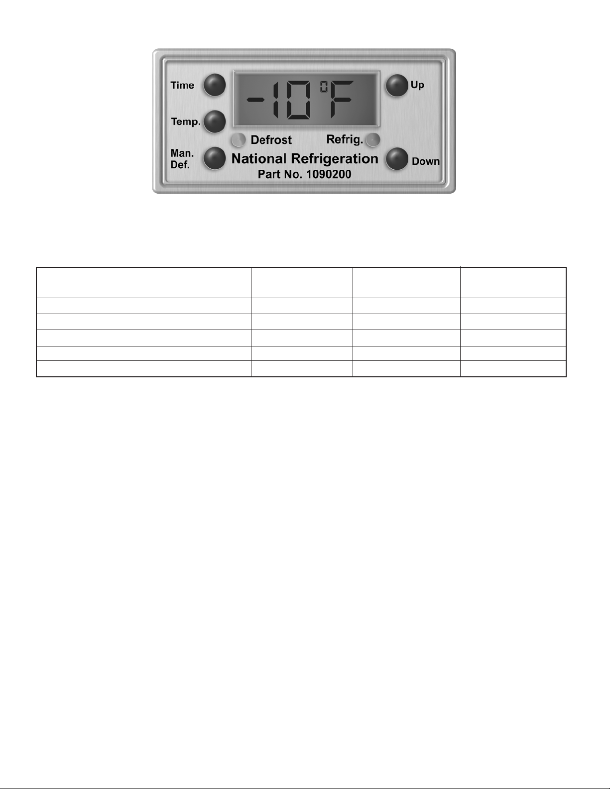
“Temp” Button Functions
To view TEMP settings (in sequence listed below), push and release the “Temp” button.
To adjust settings, hold down the “T emp” button while pushing “Up” or “Down” buttons.
Function Display Adjustment Factory Default
Shows: Range: Setting:
Temp (zone) set point cut -in “SPº / -10ºF” -40 to 99ºF -10ºF
T emp (zone) set point differential* “difº / 04ºF” 2 to 25ºF 4ºF*
T emp (evap) actual temperature “Evap” / actual ºF NA NA
Fan delay temp (fans cut-in) set point “Fdº / 25ºF” 15 to 30ºF 25ºF
Defrost termination temp cut -in set point “dtº / 55ºF” 40 to 70ºF 55ºF
* CAUTION: “Cut-Out” = “Cut-In” - “Diff”
Increasing this factory difº value will result in longer compressor running times and colder room temperature. Decreasing this factory difº value
will result in short compressor running on/off cycles.
“Man. Def” (Manual Defrost)
Button Function
This will immediately START a manual defrost
cycle if in refrigeration mode. If already in a defrost
cycle, this will stop the defrost cycle if pushed a
second time. This will not affect or override any
normal defrost programming.
TESTING NOTE: The defrost cycle will not start if
the EVAP sensor temperature is at a temperature
higher than that of the Defrost Termination Set point
(55ºF). The evaporator must be at a colder
temperature.
Push and hold button for at least 5 seconds to
activate. Do not push this button on and off without
waiting at least 5 seconds between periods.
Loss of Power
In event of loss of power, all programmed settings
will remain as those at time of power loss. Clock
time will remain at time of power loss (similar to
a conventional defrost clock). When power is
restored, wait at least 15 seconds for display to
indicate the Zone temperature (default display)
Restore Original Factory Default
Settings
To restore unit to original factory default settings:
- Push “Up” and “Down” buttons simultaneously
and hold for at least 5 seconds until display “Ed”
steadily appears (1 second).
- Release Buttons.
The clock is now programmed for factory settings
on Electric Defrost mode.
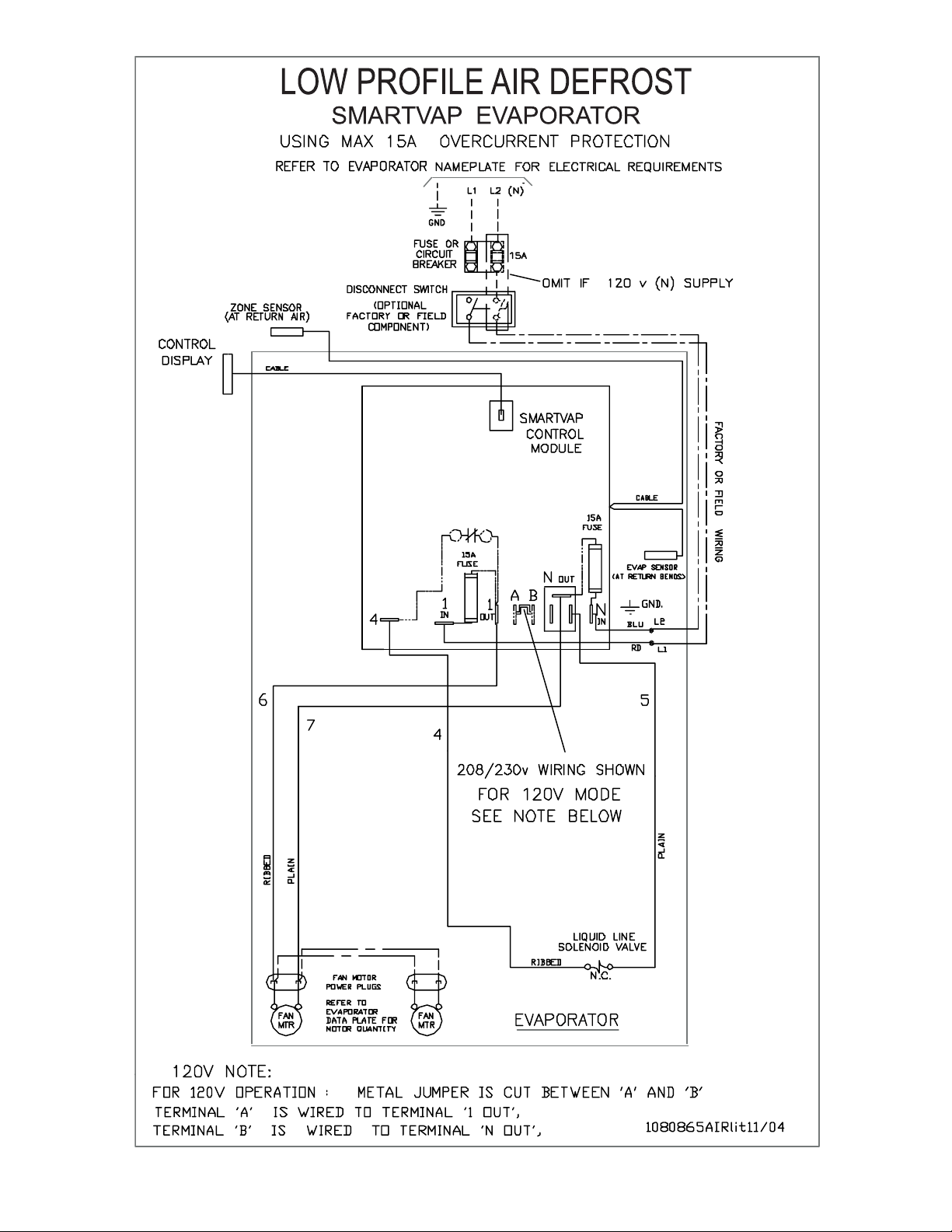
For Air Defrost (Ad):
- Push “Up” and “Down” buttons simultaneously
and hold for at least 10 seconds until display “Ad”
appears (after “Ed” disappears).
- Release Buttons.
The clock is now programmed for factory settings
on Air Defrost mode.
- 2 -
Page 3
- 3 -
Page 4

- 4 -
Page 5

- 5 -
Page 6

Troubleshooting Guide
WARNING: These guidelines are intended only for qualified service personnel familiar with
troubleshooting procedures and high voltage.
Problem
SmartVapTM control display
does not power up and
display zone temperature
Evaporator fans do not start
(Display OK and powers up)
Possible Solutions
1. Check for voltage (200 to 240V) at 1 IN and N IN (see wiring schematic
for terminal locations)— If NONE, check for voltage at field connections L1
and L2 or back at main panel service entrance. (Note: 3 and 4 Fan models have
inline 20 or 25A fuses (type LPCC or CCMR). Reject type fuse MUST be used
and inserted with smaller diameter end into holder, large diameter in
cap. If fuse(s) are blown, check/repair wiring for short before replacing fuse(s).—
If all above VOLTAGE OK, check voltage at 1 OUT and N OUT. If NONE then
check both 15A ceramic fuses. If fuse(s) are blown check for wiring short before
replacing fuse(s). (250V Rated Type ABC or MDA 15A must be used).
2. If above voltage OK, then check phone cord and cable connection at
module end. (Ensure cable is snapped in) CAUTION: KEEP FINGERS AWAY
FROM POTENTIAL VOL T AGE (terminal 3) when checking.
3. Push and hold “Up” and “Down” Display buttons together for 5 — 10
seconds. This will re-boot & reprogram the electronic clock to factory settings.
Ensure “Ed” mode (Electric Defrost) is selected.
4. Contact Factory
1. Check to see if display indicates “Defrost” mode (Yellow LED on).
Evaporator fans are designed to be shut off during defrost and after a defrost
cycle fans will not re-start until temperature reaches 25ºF at “evap” sensor.
2. Check connection of orange jumper from C to 1 OUT. Check voltage at
C and N OUT
— If NONE, see fuse checks above on “Display” troubleshooting
— If OK, check voltage at F and N OUT, If OK check fan wiring and voltage
at plug (motor end).
3.Check fan delay temperature setting (Factory pre-set at 25ºF) and readjust higher if required.
4. If fan delay setting is OK, check sensor at rear of unit cooler in return
air stream (top left hand side -in front of fins) Is it tagged “ZONE”? If tagged
“Evap”, switch sensor locations. (Move “Evap” sensor to correct location at return
bends.)
5. Contact Factory
- 6 -
Page 7

Problem
Possible Solutions
Refrigeration cycle will
not start (Display OK and
powers up)
Defrost heaters do not energize (Display OK and powers
up)
Poor Refrigeration /
Defrosting Performance /
Drain Pan Ice Up Problems
1. Green LED light (indicates demand for refrigeration) must be on.
Box temperature must be higher than set point temperature. Check display
T emp Setting for “SP”.
2. Liquid line solenoid must be energized. Check solenoid coil with small
screwdriver to confirm there is magnetic force. If no force, check voltage at
terminal 4 and N OUT, check solenoid coil wire splices in conduit box.
3. Check, with gauges, condensing unit low-pressure control setting. Is it
adjusted low enough to cut-in?
4. Contact Factory
1. Y ellow LED light (indicates defrost cycle mode) must be on.
Defrost cycle will not start if “evap” sensor is above 55ºF. Ensure refrigeration
mode has run long enough to reduce “evap” sensor temperature below 55 ºF
2.Check for Voltage between terminal 3 and 1 IN. Check all heater wire
spade connections, splice connections and jumper connections.
3. Contact Factory
1. Refer to regular Evaporator or Condensing Unit instruction manual
troubleshooting sections.
2. Contact Factory
Contact the factory or your local Sales Representative for further information or assistance.
- 7 -
Page 8

NOTES
01/07/05
PROJECT INFORMATION
metsyS
rebmuNledoM pU-tratSfoetaD
rebmuNlaireS rotcartnoCecivreS
tnaregirfeRenohP
ylppuSlacirtcelExaF
NATIONAL REFRIGERATION
& AIR CONDITIONING CANADA CORP.
159 ROY BL VD., BRANTFORD, ONT ARIO, CANADA N3R 7K1
PHONE: 1-800-463-9517 (519)751-0444 FAX (519)753-1140
Due to National Refrigeration’s policy of continuous product improvement, we reserve the right to make changes without notice.
 Loading...