

Page 1

1-800-24 BALLY
www.mortuarycoolers.com
Installation Manual
Mortuary Cooler Systems
1. Installation Preparation 2
2. Establishing Mortuary Perimeter 3
3. Vertical Panel Assembly 3
4. Installing Door Panel 4
5. Installing Ceiling Panels 4
6. Anchoring Mortuary Cooler 4
7. Caulking Mortuary Cooler 5
8. Installing Refrigeration Unit 5
9. Installing SaniTray Rack and Tray 5
10. Installing Telescoping Tray 6
Assembly of a 6 or 9 Body Cooler 7
REV: 6/2014 IM-418-11 © 2014 Bally Refrigerated Boxes, Inc. 1
Page 2
Please read this instruction and any other installation material provided before starting the assembly of Bally
Figure 1
Figure 2
Figure 3
Mortuary Cooler. A plan showing the proper locations of panels is enclosed.
1. Installation Preparation
A. When the building is delivered, make sure you have the right equipment and manpower on hand to unload the
truck. A forklift or high jack can be helpful if the shipment includes heavy steel or refrigeration equipment. The
carrier typically imposes time constraints on unloading your box, and in all situations one person is not enough.
B. As you are unloading look for any freight damage; all products left our factory in perfect condition. Once the Bill of
Landing was signed by the carrier, safe delivery became their responsibility and the equipment became your
property. Check the packing list and make sure that all component parts are accounted for. Before signing the Bill
of Landing, inspect all items. If any damage is noted or the number of pieces received does not agree with the
invoice, do not accept shipment without notation by the carrier’s agent on the Freight Bill. If damage or shortage
is discovered when unpacking leave material and request an inspection by the carrier. Keep all documents and
information so you can file you claim properly with the carrier. The Bill of Landing, Freight Bill, and the original
invoice, are need to file a claim, and must be filed within the first six months from the date of shipment.
Do not substitute hardware or other materials supplied. If there are questions or missing components,
call the Bally Mortuary Sales Department at 1-800/24BALLY (1-800-242-2559)
C. Use extreme caution when unpacking to prevent damage to panels and other equipment. Pay close attention to
hardware affixed to the door and door-frame. Do not lift the door by its Hardware or the Light Base. Do not drop
panels or slide over unfinished surfaces. Keep panels dry and out of direct sunlight. The protective plastic coating
on the panels may be removed before or after the installation depending on the timing of construction schedules.
D. Check the packing list and make sure that all components are included in the shipment.
E. The most important requirement for o successful assembly is that the floor is level so that the panels will align
correctly and be plumb. Have a plumb line and level available during the installation and check panel plumbness
and levelness frequently.
F. The vertical and door panels are pre-numbered and must be positioned as depicted in the Plan View.
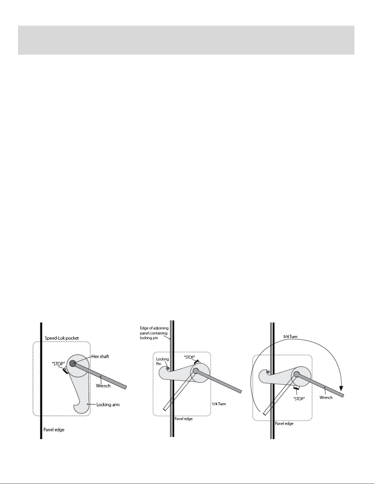
G. Familiarize yourself with the operation of the Speed-Loks. Study the figures and perform o few trial locks before
actual assembly. Speed-Loks are accessed from the interior of Mortuary Cooler. Turn Speed-Lok wrench clockwise
to engage the locking arm. See Figures 1, 2 and 3.
REV: 6/2014 IM-418-11 © 2014 Bally Refrigerated Boxes, Inc. 2
Page 3

Establishing Mortuary Cooler Perimeter
Figure 4:
Check Perimeter Outline
Figure 5:
Check Floor level
Figure 6:
Position Vertical Panels
A. The following instructions cover the erection of Mortuary Coolers that do not include Bally floor panels and
are shipped unassembled.
B. Mark the outside perimeter of the Mortuary Cooler on the building floor. Check the marked area for
squareness by measuring the distance across the corners as shown in Figure 4. Check floor for levelness. If
floor is not level, the panels will need to be shimmed to maintain the height of the highest point of floor.
Determine the highest point of floor using o 48" spirit level. If needed, establish a level string to help set
vertical panels. See Figure 5.
Vertical Panel Assembly
A. Position the first corner panel (#1) so the
outside of the panel is flush with the
perimeter line. If necessary, shim corner panel
to be level with the highest point of floor.
B. Position the center back vertical panel (#2) to
the corner panel and lock the adjoining side
Speed-Loks. Shim the second panel if
necessary for it to be plumb and level with
the corner panel. Ensure that the tops of the
panels are even. Insert Speed-Lok wrench
into access hole and turn clockwise until the
Speed-Lok locking arm stops. If Speed-Lok
was fully open, the wrench should make one
complete turn. See Figure 6 and 7.
C. Position the next rear corner panel and lock to
previously installed vertical panel. Check
panels for plumbness and levelness.
D. Proceed to position and lock the side vertical
panels as numbered. Check each vertical
panel for plumb and level when installed.
REV: 6/2014 IM-418-11 © 2014 Bally Refrigerated Boxes, Inc. 3
Page 4

Figure 7:
Lock Verticals Even at Top
Figure 8:
Mortuary Cooler Anchoring
Installing Door Panel
A. Remove the steel-shipping strap mounted at
the bottom of door panel opening. Position
door panel and align with vertical panels
previously installed.
B. Door panel is considerably heavier than vertical
panels and needs to be handled by at least (2)
able-bodied personnel. Ensure that door
panel is plumb and level and lock the
adjoining Speed-Loks. Shim door panel if
needed. If door panel is not installed plumb
and level, the door will not operate properly.
Installing Ceiling Panels
A. The Mortuary Cooler ceiling is made up of (2) ceiling panels that are locked together at the factory. Unlocking the
ceiling panels will damage the refrigeration unit opening.
B. Place ceiling panels on top of Mortuary as shown on the plan view. Align the edges with the vertical panels and
lock top Speed-Loks.
Anchoring Mortuary Cooler
A. Vertical panels are mounted to the building
floor using continuous angle, concrete anchors
and self-drilling metal (TEK) screws.
B. Angles are shipped in stock lengths and must
be cut before installation. Calculate angle
length by measuring inside of wall panels and
subtract 4 ". Angles will start 2" from each end
wall. See Figure 8.
C. Set angle along bottom of vertical panels with
larger holes on floor and mark concrete anchor
holes with a builders crayon or similar method.
D. Drill ¼” hole 2" deep in concrete at marked
locations. Set angles back in place and install
concrete anchors. Install self-drilling metal
screws (TEK) through upright leg of angle
through predrilled holes.
REV: 6/2014 IM-418-11 © 2014 Bally Refrigerated Boxes, Inc. 4
Page 5

Caulking Mortuary Cooler
Installing Refrigeration Unit
Figure 9:
Clamp Detail for Body Tray Racks
Figure 10:
Assembly of Body Tray Rack
A. Make final checks of Mortuary Cooler panels for
a square and plumb installation. Add or
remove shims as needed.
B. Caulk bottom of the exterior and interior of wall
panels using a silicone sealant that is mildew
and waterproof.
Ensure that refrigeration unit is not stored or moved from horizontal.
Installing SaniTray Rack and Tray
A. The SaniTray cross members and side rails on the
1-3 body cooler are identical.
B. Position cross members within vertical channel
slots with the ball bearing side facing up and the
open side facing to the rear. Install clamps halves
and hardware and tighten when cross member is
level and at desired height. See Figure 9 and 10.
C. The guide channels are marked left and right and
top, middle (if there is a third tier) and bottom.
These must be positioned as marked. It will be
easier to adjust and secure guide channels if
bottom guide channels are mounted first and
then the next immediate levels.
D. Position bottom level guide channels with the
open ends facing inwards. Install mounting
hardware loosely and slide body tray fully into
Mortuary Cooler. Align body tray within guide
channel adjustment to slide straight out of
Mortuary Cooler. Tighten hardware for guide
channels. Guide channels should fit loosely
against body tray. Remove body tray out the way
before installing next row of guide channels.
A. Refrigeration unit is positioned as shown on plan view.
Use the listed weights of refrigeration units to determine
the method of lifting. The end of the refrigeration unit
that is opposite of the bottom vent is the heavier end
containing the compressor. Cardboard placed on top of
Mortuary Cooler will help slide refrigeration unit into
place and protect exterior finish.
REV: 6/2014 IM-418-11 © 2014 Bally Refrigerated Boxes, Inc. 5
Page 6

Figure 12:
Installing the Telescoping Body Tray Assembly
Figure 11:
angle.
Proper order in which the clamps should be attached.
Figure 13:
1. With the back and two sidewalls erected and fastened together, place the
telescoping tray assembly into the partially constructed box. See Figure 11.
Insure that the ends of each cross brace are inserted into the vertical
struts. See Figure11a.
2. Raise and suspend the assembly to the desired height with temporary
supports. See Figure12.
3. At this time, securely fasten the cross braces to the supports struts with the
furnished clamps. See Figure 13.
Figure 11a:
Assembly tray inserted
into the vertical struts.
Telescoping tray
inserted at a 45°
Cross braces attached to
struts with clamps.
See Figure 9 on pg 5.
REV: 6/2014 IM-418-11 © 2014 Bally Refrigerated Boxes, Inc. 6
View of raised tray
assembly on
temporary supports.
 Loading...