

Page 1

1-800-24 BALLY
Bally Refrigerated Boxes, Inc.
www.ballyrefboxes.com
Modular Buildings
Installation Manual
1. Introduction 2
2. Marking Installation Area 2
3. Speed-Lok Operation 2
4. 'Z' Base Trim 3
5. Less Floor Walk-Ins 3
6. Floor Panel Installation 4
7. With-Floor Installation 4
8. Door Panel Installation 4
9. Multi-Compartment Walk-Ins 5
10. Interior Steel 5
11. Shear Plates 5
12. Batten Strips 5
13. High Wind Securing 6
14. Outdoor Considerations 6
15. Door Rain Shield 6
16. Wall Standards 6
17. Panel Penetrations 7
18. Prevent Vapor Leaks 7
19. Grounding 8
20. Broken or Stripped Locks 8
REV: 1/2013 Instruction Manual IM-238-94 2013 © Bally Refrigerated Boxes, Inc. 1
Page 2
1. Introduction
A. When the building is delivered, make sure you have the right equipment
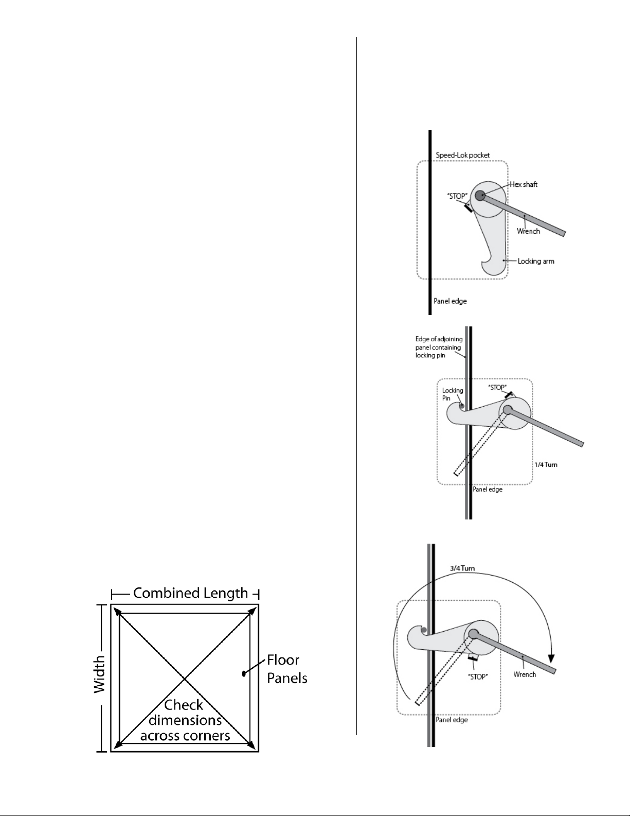
3. Speed-Lok Operation
Before attempting to erect panels, familiarize
Figure 3
Figure 2
Figure 1
and manpower on hand to unload the truck. A forklift or high jack can
be helpful if the shipment includes heavy steel or refrigeration
equipment. The carrier typically imposes time constraints on unloading
your box, and in all situations one person is not enough.
B. As you are unloading look for any freight damage; all products left our
factory in perfect condition. Once the Bill of Landing was signed by the
carrier, safe delivery became their responsibility and the equipment
became your property. Check the packing list and make sure that all
component parts are accounted for. Before signing the Bill of Landing,
inspect all items. If any damage is noted or the number of pieces
received does not agree with the invoice, do not accept shipment
without notation by the carrier’s agent on the Freight Bill. If damage or
shortage is discovered when unpacking leave material and request an
inspection by the carrier. Keep all documents and information so you
can file you claim properly with the carrier. The Bill of Landing, Freight
Bill, and the original invoice are need to file a claim, and must be filed
within the first six months from the date of shipment.
C. Use extreme caution when unpacking to prevent damage to panels and
other equipment. Pay close attention to hardware affixed to the door
and door-frame. Do not lift the door by its Hardware or the Light Base.
Do not drop panels or slide over unfinished surfaces. Keep panels dry
and out of direct sunlight. The protective plastic coating on the panels
may be removed before or after the installation depending on the timing
of construction schedules.
D. The most important requirement for installation of this Walk-In is to have
a level floor. If the floor is level the process will be very smooth.
Otherwise, it’s impossible to make sure that the panels will align correctly
and be plumb and level. Use a laser level or transit to identify the high
spots on the floor. Whenever Walk-Ins are to be installed where concrete
is curing or tile is being set, it is important to provide adequate
ventilation. Concrete and tile grout release hydrogen while curing,
which can damage the finish.
2. Marking Installation Perimeter
The most important requirement is that the Modular Building is installed
over a complete and level floor. This will ensure that the vertical panels
will align correctly and be plumb. Locate and mark the outside
perimeter on the surface where the Modular Building will be installed.
Check marked area for squareness by measuring across the corners.
yourself with the operation of the locks Figures 1, 2,
and 3. On Bally panels, locks will always be on the
left turning in clockwise rotation. If for any reason
you have to unlock a panel, refer to Section 19.
REV: 1/2013 Instruction Manual IM-238-94 2013 © Bally Refrigerated Boxes, Inc. 2
Page 3
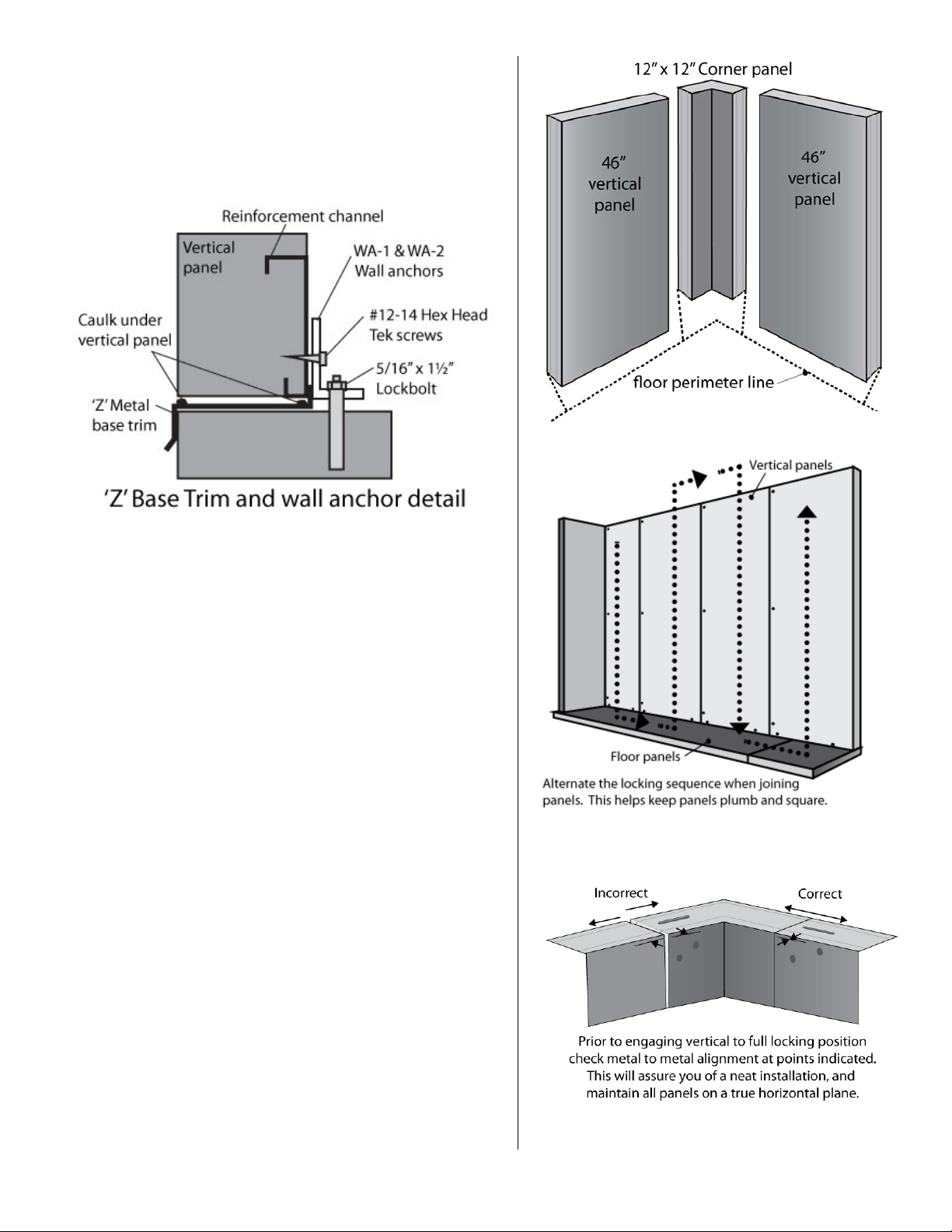
4. "Z' Base Trim (Optional)
'Z' Base trim is installed along bottom edges of Modular Building that
Figure 7
Figure 4
Figure 6
Figure 5
are flush with concrete pad. 'Z' Base trim is outlined and installed on
concrete pad before the placement of vertical panels. 'Z' Base trim
should be secured to concrete pad by installer. Vertical panels will be
secured with wall anchors after Modular Building erection. Apply
caulk along exterior and interior seam along vertical panels and 'Z'
base trim. See Figure 4.
5. Installation of Less-Floor Walk-Ins
A. After you have checked that the building floor is level, use a transient
or builders level to find the highest point on the perimeter. Position
the first 12 x 12 corner to be level with the high point. Begin at
corner and align panels at the top. See Figure 5.
B. Position a vertical panel to the right and left of the corner panel (as
per Plan View) and flush with the perimeter line. See Figure 7. Once
these panels have been aligned properly, fully engage all vertical-tovertical locks.
C. Level these panels to the perimeter high point and check for plumb
with a 48” spirit level. (Panels over 10’ in height should be checked
for plumb with a plumb bob.)
D. As each panel is installed, check to make sure it’s plumb and level. If
the panel is not plumb, shim to adjust for plumb. Making the same
check down the panel’s leading edge shows whether it’s level along
the top or not. If not adjust accordingly.
E. Continue installing vertical panels in the same manner, periodically
checking to make sure that panels remain plumb and level. See
Figure 6. (staggered locking sequence).
F. When enough vertical panels are set to accept the installation of the
first ceiling and end panel, begin assembly of the ceiling panels. See
Section 7 for method of installing remaining vertical and ceiling
panels.
G. With installation complete, caulk the bases of the vertical panels
where they meet the concrete floor.
REV: 1/2013 Instruction Manual IM-238-94 2013 © Bally Refrigerated Boxes, Inc. 3
Page 4

6. Floor Panel Installation
A. Make sure the floor is level. The entire area beneath the Walk-In floor should be
7. With-Floor Installation
Begin by erecting the 12” x 12” vertical
ed to one another.
F. When all walls and ceiling panels are in
place, lock all vertical panels to floor panels.
8. Door Installation
hinge at a time and do not loosen hinge base screws while door is open.
covered with a heavy polyethylene vapor barrier to prevent possible damage by
moisture.
B. Check drawings for any special panel configuration, then place a 23½” wide
floor end panel along the most logical starting point (usually the furthest corner,
if to a building wall if possible). Be sure the panel is a floor panel. All floor
panels have extra-heavy gauge metal on the interior for extra strength. Again,
make sure panel is level to high point of concrete slab.
C. Set the first floor panel section in place, then install the next panel and align.
Leveling occurs every time a new panel is installed. Remember to level to the
high point of the concrete slab.
D. Install shims (such as cedar shakes) under corners and cross panel joints as
needed to ensure proper support and levelness of panels. Be sure the shims are
not more than 23” apart at any given point under the panel. Place additional
shims, equally spaced, along the door frame area. This is done in order to
support the panels properly and eliminate any potential sagging.
E. Continue to install floor panels as per Plan View, locking each panel to its
adjoining panel. Make sure to keep ends or panels even with one another.
Continue until all floor panels are assembled. Again check them for levelness
and sqaureness. (Adjust if necessary.)
F. Check bottom section of door to be used to insure the proper door is being in
the proper location. Doors are specifically located by the floor plan drawing
which is enclosed with the installation instructions. A freezer door may have a
different stepplate condition than a cooler door. Follow the suffix 01 – 02 that
corresponds to the drawing.
G. If structural steel is required it should be located and installed before installing
further.
A. Determine the critical areas to find a starting
point. On smaller Walk-Ins the most critical
area is the door location. This section of the
Walk-In must be perfectly plumb and square
to insure proper operation of the door.
B.
corner panel at a convenient corner, if the
Walk-In is being installed near a building
start at a corner nearest that. Note that the
Speed-Lok holes must always be on the lefthand side when facing the interior of the
panel.
C. Next, erect the vertical panels called for by
the panel view to the right and left of the
corner panel. Make sure to align the tops of
the panels. This will help to insure that the
panels remain plumb and level. Lock these
panels together and check to make sure the
lock is engaged in the pin box properly. Be
sure the proper metal finish is exposed
where specified on the plan view.
D. When enough vertical panels have been set
to allow installation of the first ceiling panel,
install the panel walls in an order that will
allow a ceiling section to be installed before
proceeding with more panel walls. The
ceilings should be fasten
When two or three ceiling panels are in
place, lock the first ceiling end panel to the
vertical panels to prevent shifting.
Door sections are held down through the
threshold plate. Drill through thresholds’
pre-drilled holes into floor. Secure to floor
with screws provided. See Figure 8.
A. When erecting a door panel for an installation on a concrete floor and without Bally floor panels, it is necessary to provide a cutout in
the concrete floor for all freezer applications so that the heater channel may be inserted to prevent icing. Doors intended for Coolers
are simply set on top of the concrete.
If your door sticks out at the top your frame is not plumb; you’ll need to move the bottom frame in or out to correct this problem.
•
If the gap at the top of the door is inconsistent your frame is not level and the door latch may not work properly. Shim the low side
•
of the frame to level it with the high side.
B. Caulk and seal any gaps under panels or door to floor. Apply base trim as per plan view. For outdoor installation it is recommended
that all exterior panel joints be caulked during installation.
C. Troubleshooting: Check if door panel is square and plumb with 48" spirit level. To adjust door panel, loosen side, top and bottom
Speed-Loks and tap with wood block and hammer. Adjust either interior or exterior of door panel. If Modular Building door is
installed properly, no shimming is required. Shimming should only be used in conditions were the existing floor is very uneven or in
cases of poor installation. Check if door cap is toed out at top or bottom within door panel. Loosen the hinge base screws on door
panel and install shims at diagonally opposite end of door cap that is toed out. Do not loosen hinge base screws of more than (1)
REV: 1/2013 Instruction Manual IM-238-94 2013 © Bally Refrigerated Boxes, Inc. 4
Page 5

9. Multi-Compartment Walk-Ins
should always be on the colder compartment side, usually the freezer.
Shear plate locations are described on the
plan view of the Modular Building. Shear
Batten strip locations are described on the
y. Tekscrew centers should be
lateral steel. Install lateral steel as shown on plan view details.
Tekscrews through RA-1 tabs to secure to interior steel.
A. The most common arrangement for a Walk-In is a two compartment
Cooler/Freezer combination. Installation of panels in this situation is the same as
described above. The use of a “Breaker” or “Tee” panel is used to separate the
different compartments. These panels will be either 23” or 46”; typically the
verticals are the opposite of the ceilings and floors.
B. The Partition Wall will have at least two special panels referred to as P-1 and P-2.
The panel widths are either 7.6” or 9.1” and are marked with a special blue sticker
that corresponds to the drawing. The P-2 panels are double tongued (hook
pockets on both sides) which allows for final locking of the partition wall.
C. In large multi-compartment Walk-Ins, (three compartments or more) it is very
important to control the alignment of the panels and make sure if there is any
growth in the vertical panels that they are growing at the same rate as the
ceiling and floors. A quick and accurate way to check for correct alignment is to
measure the distance from the edge of the ceiling to the nearest vertical panel
joint. This measurement must be 11½”; it must be maintained at every joint to
assure proper assembly of the Walk-In. In these instances we recommend that
after the floors are placed and leveled that the center most partition be the
starting point and to work toward either end of the box.
D. Look at the plan view and take special note of which side of the panels the
wrench hold are on.
If there is not a door in the partition wall the panels will lock to ceiling and floors in
either orientation. An error on the partition wall could cost many man hours to
correct. The entire box will most likely have to be taken down to correct this error
because condensation will occur. As a general rule of thumb, the wrench holes
10. Interior Steel
A. Interior steel framework is assembled before Modular Building assembly. Details
and layouts for interior steel are given on the plan view. Steel pieces are painted
primer and are numbered for identification.
B. Mark the exact outside perimeter as previously described. Check that outline is
square. See Section 3.
C. Using the plan view and base plate details, mark the positions of centerlines in
relation to perimeter. Once base plate locations are anchor bolt locations can be
determined using base plate details. See Figure 9.
D. If the floor surface is considerably uneven, find the highest point of steel column
positions and level all other columns to this height using leveling grout or plates
11. Shear Plates
plates are installed over Speed-Lok locations
using 6 self-drilling Tekscrews provided by
Bally.
12. Batten Strips
plan view of the Modular Building. Batten
Strips are installed over vertical and/or
ceiling joints. Batten Strips are to cut length
and installed using Tekscrews provided by
Ball
approximately 2" from ends and 8" center to
center.
(Supplied by installer).
REV: 1/2013 Instruction Manual IM-238-94 2013 © Bally Refrigerated Boxes, Inc. 5
Note: Depending on architectural specifications, J-bolts can be
foamed into concrete when slab is poured or anchor bolts after
concrete slab is cured. Place all columns into position and
secure them to concrete slab. Plumb columns and position
When ceiling panels are assembled, install provided self-drilling
Page 6

13. High Wind Securing
The following high wind anchoring methods are suggestions and
Bally supplies door canopies for outdoor installations. It is
16. Wall Standards for Mounting Equipment
ion standard against vertical panel with one end
level. Mark hole locations with maker and drill using
Hold ceiling bracket in against ceiling panels and mark
screws and
Figure 11
are not inclusive of all possible anchoring methods. The type of
anchoring and the space between tie downs are dictated by local
building codes. All materials used are provided by building installer.
A. Anchor Bolt Through (For Modular Buildings with floors only):
Anchor bolts are located in concrete prior to Modular Building
installation. Anchor bolt locations should avoid floor panel
penetration limits and compression plates should be at least ½”
from interior of vertical panels.
B. Eye Bolt and Hold Down Cable: Anchor bolts are located in
concrete prior to Modular Building installation. Light Structural
Member determined by local building code advisory. Light
Structural Member should be placed as to not trap water.
Precautions should be taken to prevent Light Structural Member
from chafing exterior membrane roof.
C. Earth Anchor and Hold Down Cable: Earth Anchors can be
located after Modular Building installation. Installer should use
Anti-Flutter Padding to keep hold down cable from chafing
exterior roof. Distribution angle should be at least 18" to allow
hold down cable to migrate and allow ample load distribution.
14. Outdoor Considerations
All outdoor installations require some type of weather roof to cover
the top of Modular Building.
A. Aluminum Roofs are available for buildings that have a wall width
of 34' 7" or less. See Instruction Manual IM-276-90.
B. Membrane (polyvinyl sheet) Roofs are available as dictated by
building specifications. See Instructions for Membrane Roof.
Wall post locations are determined by customer equipment
arrangement within Modular building. Please note the
location limits shown. See Figure 10.
A. Posit
touching ceiling panels. Check standard plumb with 48"
3/32" drill. Do not punch holes. Install standard with #8½” screws. Install screws in all wall post mounting holes.
B. Temporarily install ceiling bracket with (2) clamps halves,
(1) 3/8" x 1¼" bolt and (1) 3/8" nut at top of standard.
the (4) mounting holes with marker. Drill 3/32" holes and
install ceiling bracket with (4) #8-½”
previously mentioned clamp. See Figure 11.
C. Ceiling panel exterior joints must be caulked with silicone or
other waterproof sealant after assembly. Floor panels must be
elevated above immediate area of installation. Concrete pads
must have drainage as shown in Bally floor detail on plan view.
Installation must not allow water to seep under Modular Building.
15. Door Canopy
recommended that canopy be installed over door opening to
prevent water damage and icing. Apply caulking to back of canopy
mounting flanges. Form fillet with caulking when canopy is mounted.
Install canopy centered and level over door opening with provided
self-drilling Tekscrews. Canopy height should be high enough to clear
door operation.
REV: 1/2013 Instruction Manual IM-238-94 2013 © Bally Refrigerated Boxes, Inc. 6
Page 7

17. Panel Penetrations
If penetrations in panels are needed, avoid the areas
18. Prevent Vapor Leaks
is installed settles. If the internal
across from the vapor leak which can make locating a leak
All wall penetrations should be sealed. This includes any
that are shown. Penetrations should be made as needed
by competent installer or mechanical service. If shaded
areas are avoided, urethane insulation can be easily
removed from opening. After equipment installation, fill
in hole with permagum caulk. See Figure 12.
Condensation in electrical junction boxes can be
eliminated by installing a seal-off fitting in conduit
where they pass through Modular Building walls.
A. Modular panels are square and dimensionally accurate so in most
installations they will seal effectively against vapor leaks. However
in some unusual cooler applications, minor vapor leaks may occur.
The leaks can occur if the panels follow slab variations or if the
building in which the Walk-In
temperature is cycled periodically, the expansion and contraction
of building materials will cause enough movement to allow some
vapor penetration.
B. Unfortunately, internal dripping does not always occur directly
troublesome. In order to avoid time-consuming search procedures,
caulk the exterior junction of three or more panel joints. Most leaks
caused by settlement will be at these points.
C.
protruding clips or hangers installed in panels joints.
D. Use either industrial-grade or silicone calking. When silicone is
used, sealed areas must be cut opened whenever the panels are to
be disassembled for relocation or enlargement.
REV: 1/2013 Instruction Manual IM-238-94 2013 © Bally Refrigerated Boxes, Inc. 7
Page 8

19. Grounding
Figure 13
Ensure that all protective plastic coating is removed from
panels.
A. Install Angled Batten strips along interior top of Vertical
panels using #8 3/4" Metal screws (Install Angled Batten
strips along interior bottom of Vertical panels if Modular
Building has Floor panels). Install Braided copper wire at
every Speed-Lok location for Ceiling end panels using #8
2-1 /2” Metal screws (Install wires at Speed-Lok locations
for Floor panels if equipped). Install Metal screws in line
with Speed-Lok holes and at least 3" from edge of panel.
B. If Modular Building does not have a Bally aluminum roof,
install exterior Batten strips using #B 3/4" Metal screws.
C. Install #8 2-1 /2" Metal screws at Speed-Lok locations on
both legs of Corner panels. Install Metal screws at the
same height of Speed-Loks and at least 3" from edge of
Corner panel.
20. Broken or stripped locks
A. The panel contained the lock must be slid away from adjacent
panels in order to obtain adequate working space. First check for
any obstructions (dirt, foam, etc) once you have unlocked a panel
reset the cam stop by turning the lock fully back to it’s original
position. If the hook is broken or stripped replacements can be
found in Miscellaneous Parts Box#1.
B. Position the lock wrench on the hex rod and turn clock-wise until
the locking arm protrudes. See Figure 13.
C. Place your hand near the bend in the wrench as shown in Figure
5 and use a lift-up motion. This will produce a clamping action
on the hex rod. While doing this, pull forward until the rod is free
of the panel. The locking arm will then drop free.
D. Hold the new locking arm in position. Make sure the hook of the
arm faces in the proper direction. See Figure 14
E. Insert the new hex rod into the lock hole. Care must be taken to
insert the notched end of the rod. The end to be inserted has a
notch located 1” from the end. This notch acts as a stop so the
rod will not be inserted too far.
F. Align the hex rod with the hex hold of the locking arm; gently tap
it until the notch stops against the locking arm.
G. Replace and refasten the panel in its original position.
1-800-24BALLY
ballysales@ballyrefboxes.com
Phone: 252.240.2829 | Fax: 252.240.0384
135 Little Nine Drive Morehead City, NC 28557
www.ballyrefboxes.com
REV: 1/2013 Instruction Manual IM-238-94 2013 © Bally Refrigerated Boxes, Inc. 8
 Loading...