

Page 1
1-800-24 BALLY
Bally Refrigerated Boxes, Inc.
www.ballyrefboxes.com
IM-359-11 2011© Bally Refrigerated Boxes, Inc
Installation and Operation Manual
Northwind Blast Chiller
Models: 500 and 1000
.
1
Page 2

Introduction
READ ENTIRE MANUAL BEFORE BEGINNING INSTALLATION!
• There are 9 steps to the installation process. This manual gives you a correct sequence to
follow as you prepare for and carry out installation.
• Prior to the day you make the installation, be sure to review the tool list and parts list, and
the illustrated plan so that you can complete the installation in a reasonable time without
any problems.
• There is also a precise wiring diagram included for any complication and step-by-step
instructions to make the job that much easier.
• No manual can anticipate every field situation, but if there are any questions not answered
here, please feel free to call the Bally Northwind help desk at 800-242-2559. Our staff of
troubleshooters will do their best to assist you.
2
Page 3

Table of Contents
Title Page Number
Introduction 1
Tool List 4
Parts List 4
Step 1 – Locating the Blast Chiller 5
Step 2 – Panel Preparation 5
Step 3 – Erection of Vertical Panels 6
Step 4 – Installation of Ceiling Panels 7
Step 5 – Secure all Panel Sections 8
Step 6 – Installation of the Controller 8
Step 7 – Installation of Coil & Fan Assemblies 9
Step 8 – Cable Connections 12
Steps 9 - 11 – Final Assembly 12
Operation Introduction 13
1 - Controller Description & Operation 14
2 – The Probes 14
3 – Automatic Mode 14
4 – Defrost Mode 16
5 – Manual Mode 17
6 – The Red Light (Critical Failures) 17
7 – Maintenance Items 18
Major Component of the Blast Chiller Back Cover
3
Page 4
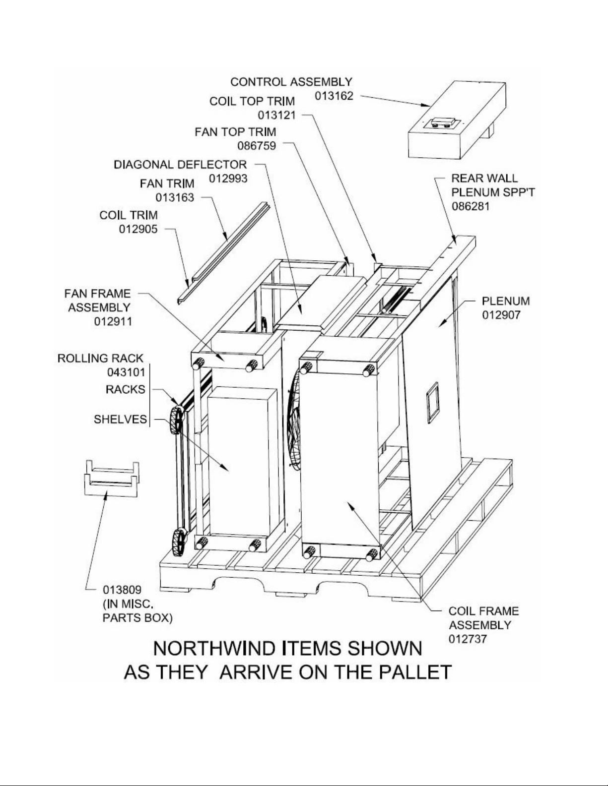
Note: 012993’s are sometimes left out (see Chapter. 6.3)
4
Page 5

Bally Northwind Tool List
Two people are required to assemble a Bally Northwind. The following list will assist you on the tools
necessary in the assembly process.
1. Caulk Gun (tube type)
2. Utility Knife (for foam insulation)
3. Foaming Kit (in the general miscellaneous box*)
4. Speed Lock Wrench (in general miscellaneous box*)
5. Tape Measure
6. Level (at least 4 ft.)
7. 5/16 Nut Driver
8. Straight Edge (i.e., carpenters square)
*You will find two Miscellaneous Parts Boxes: the General Box, with parts for the normal walk-in portion of the
job, and the Blast Chiller Miscellaneous Box, with dedicated parts of the Blast Chiller.
Bally Northwind 500 Parts List
1. 23” Panels [3]
2. 34 ½” Panel [1]
3. Corners [4]
4. Ceiling Panels [2]
5. 36” x 78”Door (with electrical junction box, complete with twist-lock plug wiring). [1]
6. Control Panel (with complete twist-lock plug wiring and buzzer with alarm switches) [1]
7. Fan rack (pre-assembled) with twist-lock plug wiring [1]
8. Evaporator Coil (pre-assembled) with twist-lock plug wiring [1]
9. Probes, thermocouple type K [3]
10. Ceiling Plenum with light and twist-lock plug wiring [1]
11. Top Coil Trim with J-box for Thermocouples[1]
12. Top Fan Trim Piece [1] (Angled piece, approx. 4 x 36”)
13. Coil and Fan Trim Pieces[2 each]
14. Top Diagonal Air Deflectors (for above Coil and Fan assembly) [2].
15. Universal food rack with tray supports [1]
16. Door Anchor [2] (UNLESS there is a floor)
17. ¾” Stainless steel plug buttons, type 304 (48)
18. Grey panel gasket for repair of damaged gaskets
5
Page 6
1. Locating the Blast Chiller
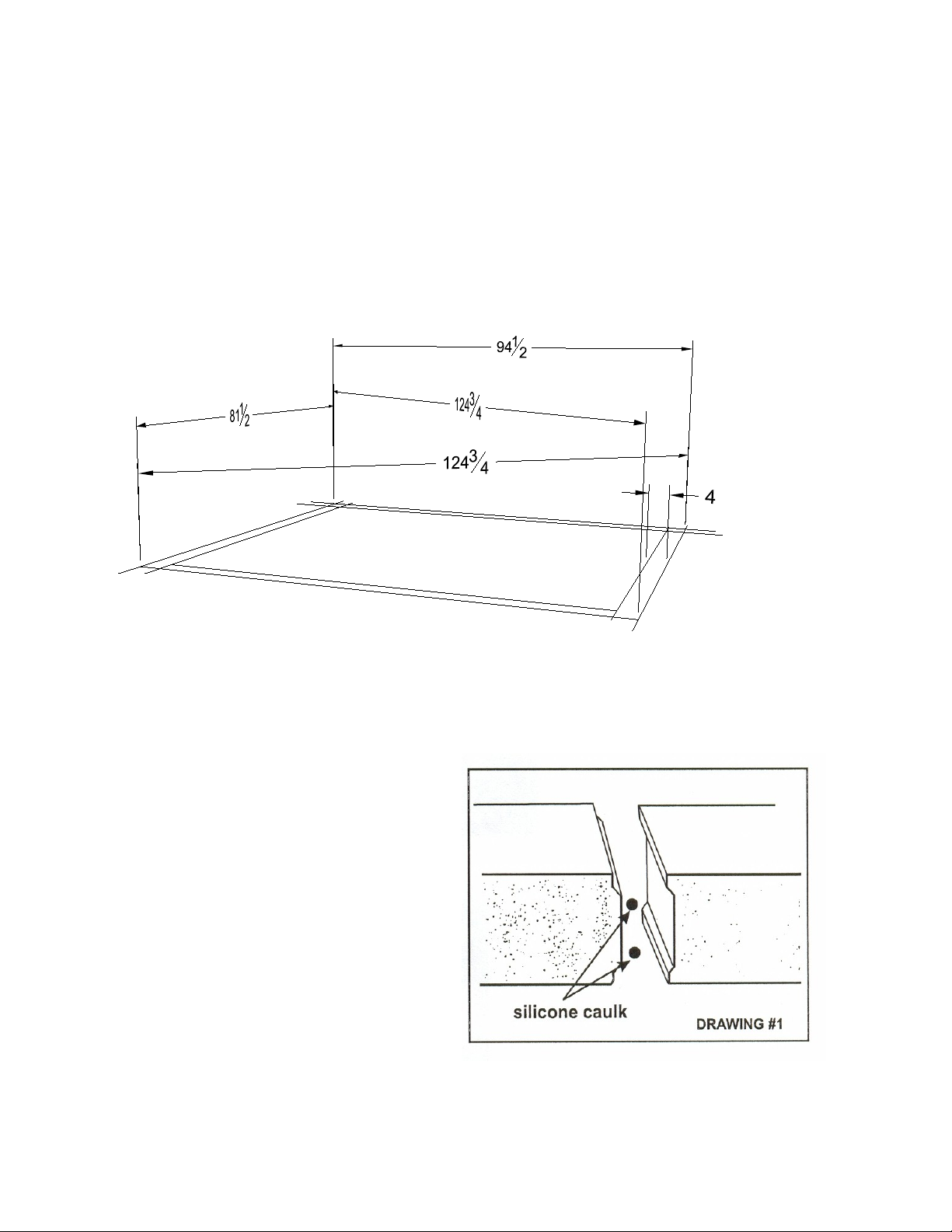
1.1. Using a chalk line and a carpenter’s square, locate on the building floor, the exact dimensions of
the blast chiller as shown in the supplied print. After marking the exterior rectangular
dimensions, measure inward 4” around the perimeter to form an interior rectangle, which locates
the interior blast chiller dimensions.
2. Panel Preparation
2.1. Remove all protective paper from
panels. Leave all special labels on the
skins.
2.2. During the course of installation, the
panels must be caulked for proper seal.
This detail is to be applied to all panel
joints throughout this instruction.
Using the tube of clear silicone
supplied, run two [2] vertical beads of
caulk (see drawing 1.1) on the interior
foam seams.
6
Page 7

3. Erection of Vertical Panels
Panel assembly sequence of a Northwind 500
3.1 BEFORE ATTEMPTING TO ERECT ANY PREFAB SECTIONS, FAMILIARIZE YOURSELF WITH THE
FOLLOWING CHAPTERS IN THE STANDARD INSTALLATION MANUAL (IM-268-11, Revised
2011):
• Page 4, Section 1
• Page 5, Section 2
Operation of the Bally Speed-Lok
• Page 7, Section 3
Bally Boxes without Floors
3.2 Start by erecting a vertical rear corner
section. When erecting, the holes for the
Speed-Lok wrench must always be on the
left-hand side when facing the interior section.
This is important; crews have installed boxes
upside down.
• The Coil Frame Assembly is installed in the box
before the door is added since the coil is taller than
the opening of the door. You’ll have to slide the
coil out of the way to lock the last corner panel.
• When erecting the front sections of the box, note
that the door latch corner and the door frame
section have a cut out at the top of the panels,
which, when joined, will provide a slot through
which the collar of the control panel will be
inserted.
• Install this cut out corner first, making sure that the
two bottom surfaces in the notch area are perfectly
level.
For the NW 1000 sequence, look in the Appendix.
7
Page 8

3.3 On each panel, check for proper
Installing Ceiling Panels on the Northwind 1000
and remove the cardboard.
alignment and level. Leveling can be
accomplished by placing wooden shims
under the vertical panels (cross-
reference IM-268-11, Section6).
3.4 Remove the shipping strap attached to
the bottom of the door opening. When
attaching the door, hold a level on the
face of the door section, and when
plumb, Speed-Lok to adjacent corner
section. IT IS VERY IMPORTANT THAT
THE DOOR SECTION IS ALWAYS LEVEL
AND PLUMB.
4. Installation of the Ceiling Panels
4.1. Bring the rear ceiling panel on top of
the front half of the blast chiller.
4.2. Caulk on both sides of the tongues of all the
appropriate rear wall panels.
4.3. Pick up the ceiling panel, bring it back, and
drop it in place. Engage a couple of locks on
the back wall. Do not fully lock.
4.4. Caulk the groove or tongue of the rear
ceiling panel and the rest of the wall tongue
area.
4.5. Bring up the front ceiling panel and lock it to
the back ceiling panel, fully engaging the
Speed-Loks to the lock position on the seam
between the two ceiling panels.
4.6. Make sure the ceiling panels are secured
squarely on the vertical panels. Do not fully
• Install the middle ceiling panel first. The large
panel will align more panels quicker.
• Instead of caulking the tongues, place the
caulk in the corners of the grooves in the
ceiling panel, then lay the ceiling panel on a
piece of cardboard trimmed to size.
• Lift the ceiling and cardboard onto the
verticals, locate the ceiling panel, tilt it up,
lock. Align and adjust accordingly.
4.7. Fully engage the Speed-Loks to the lock
position on the vertical panels to the
ceiling panels.
8
Page 9

5. Secure all Panel Sections
5.1 After all Speed-Loks are secured, install access hole
plug buttons to all Speed-Lok locations.
5.2 Anchor both sides of the doorframe inside the box to
the floor with “L” braces with 5/16” expansion bolts
and 5/16”hex head self-tapping screws with
shoulders to the door panel.
5.3 Using the silicone supplied, caulk both interior and
exterior of box at floor joints.
5.4 Install SS continuous angle floor anchor (Bally PN
019045) around inside periphery of the box.
6. Installation of the Controller
6.1 Have a partner hold the controller up and feed
the connectors through the controller slot in
the front of the box. Then push the
rectangular collar of the control assembly into
the slot until the base of the controller is
against the face of the blast chiller. Back out
the three screws that hold the front cover onto
the controller base. Remove the controller
cover, and screw the controller base to the wall
panel.
6.2 Two interlocking stainless steel harness covers
lock around the incoming cables of the control
panel. Secure the cover plates to the box front
panels by preparing a pilot home with 1/8” drill
and finishing with ½” stainless steel, self-
tapping, Phillips head sheet metal screws. Fill
the volume with canned foam. Fill any gaps
between the wall panels and the plastic
wrapped chute with canned foam.
6.3 Install the two top ceiling deflectors in the
upper top corners of the sides of the box
9
Page 10

deflecting the flow of air from the fan frame
Orientation of the Trim Pieces
assembly to the coil frame assembly. Prior to
installing, prepare 1/8” pilot holes and use ¾”
stainless steel, self-tapping, Phillips head sheet
metal screws.
Some tall (over 106”) boxes may not have ceiling deflectors. Check the packing list for PN 012993.
7. Installing Coil and Fan Assembly Frames
7.1 Before you stand up any of the frame assemblies, extend the
legs out to 5.0” (by spinning the foot pads).
7.2 Installing the Coil Frame Assembly
1. Remove the Coil Top Trim, 013121.
2. Install the coil frame into the appropriate side.
3. Center the frame within 1/16” between the two walls.
4. Install screws into the rear top back brace. This will force the
frame against the wall permanently.
5. Reinstall the top coil trim piece. Attach the grey plastic probe
receptacle box (from the controller) into the rectangular hole.
The Bally box design follows certain rules. One of the results is that a wall that two corners on it will be 1½”
narrower than a wall made of a corner and a breaker. As a result of this, there is more room in a NW1000 than a
NW500. To make up for this extra space, the trim pieces are turned with the long legs against the frame on a
NW1000, long legs against the walls on a NW500.
10
Page 11

7.3 Installing the Fan Frame Assembly
1. First remove the fan guard.
2. Install the frame in the appropriate side and screw
the back braces to the side wall using the same
stainless steel sheet metal screws.
3. Plug in the Air Probe (see connector at top of
picture).
4. Install the two shorter side trim angles on each side
by screwing them to the walls.
5. Replacing the front cover will capture the side trim
pieces between the front cover and the frame.
6. Place the Top Fan Trim Piece between the same
front cover and the frame.
7.4 Installing the Condensate Drain
1. A tube must be installed to drain condensate from
each coil assembly.
2. Find the pan, which is approximately four inches
above floor level on the coil frame. Locate the 90°
Elbow beneath it.
3. You must supply a drain line starting from the ¾” NPT
plastic elbow. You may plumb the line to the front,
rear, or side, as per your convenience. You may use
plastic tubing, PVC pipe, or other pipe. If you are
installing a NW1000, you may join the two runs or
plumb them separately.
4. Drill a hole in the appropriate panel. Caulk the
hole(s) after finishing the plumbing.
11
Page 12

7.5 Installing the Plenum Supports and Plenum
Interior Plenum Supports on both sides of the
1. At this point, the Front Plenum Support, Fan
Seal Strip, and Coil Top Trim should be in
place. Adjust the side pieces so that they
match the front in height (usually 78”).
2. Add the Interior/Rear Plenum support(s) to the
interior wall of a NW1000. The plenum is
installed on the far side of the wall.
Plenum Installation - The plenum is installed
interior wall (on a NW1000) and rear walls. You
will find screw holes in the walls from our initial
assembly. Use these first.
3. Install the Plenum and see if the
holes line up. Screw the Plenum
to the:
(1) Front Plenum Support, then
(2) The Coil Top Trim*, then
(3) The Fan Top Trim, and finally
(4) The Rear Support (or the
Interior Support for the
NW1000).
with the electrical plug toward the coil frame. Lift
the plenum diagonally over the fan assembly.
Have somebody else plug in the connector, then
raise it until the lowest corner is above all the
plenum supports, then lower it flat.
12
Page 13

*The priority should be in that order, if the Coil Top Trim holes won’t match up when the plenum is
8.1 Interior Wiring Color Code
screwed to the Front, unscrew the Coil Frame from the wall and shift it over until it fits. The Fan trim piece
can shift side to side with respect to the frame, and you can redrill the holes in the back wall.
8. Cable Connections
• All of the interior wiring is done utilizing
color-coded, twist-lock, watertight plugs
and type J thermocouple plugs. Make sure
all plugs bottom out.
• All interior wiring must be done before the
ceiling plenum is installed.
1. TWIST LOCKS from-
Controller to:
2. “Grey +” = “Back side of NW1000”. For
Grey & Red rear defrost heaters
3. Type J Thermocouples
Three Cables Terminating at Outlet
Air probe Cable (single black receptacle)
4. Match all of the plugs together according to
Red defrost heaters
Blue solenoid valve & defrost
Green fan motors
Yellow & Brown door junction box
Door junction box to:
White ceiling plenum light
example:
Box(es)
the color code provided. Ty-Wrap all of the
cords to the bases attached to the walls for
that purpose. You will want to leave the
Plenum down for the refrigeration
technician, and it will not matter as far as
the electricity is concerned if you leave the
plenum out of the blast chiller.
termination
9. Hooking up the System
A properly licensed electrician must next hook
up the system to a shut off attached to a
nearby wall. The electrical specifications are
located on a sticker attached to the controller.
10. Installing Refrigeration
After the unit has power, the refrigeration
technician can install the refrigeration, running
½” and (usually) 1- 1/8” copper tubing through
the provided hole in the ceiling panel. Make
sure the suction tubing is properly wrapped
with Armaflex, and all work is done in good
practice according to local code. Coils arrive
with a holding pressure of 60 psi nitrogen.
11. Setting the Ceiling Plenum
The ceiling plenum can now be set in place,
plugged in, and mounted using black thumb
screws. I you have trouble lining up the holes,
remember that the fan side upper trim is
clamped in place and can be slid forward or
backwards, and you can loosen the trim piece
over the coil frame as well. Also remember
that the interior plenum support angle can be
relocated if need be.
13
Page 14

OPERATIONAL MANUAL: BALLY NORTHWINDS BLAST CHILLER
BEFORE TURNING THE CONTROLLER ON, ensure that all wire connections are secure and correctly color coded.
Inspect all of the external wiring according to the wiring specications.
WARNING: DO NOT OPERATE THE NORTHWINDS CONTROLLER WHEN THE CONTROL COVER HAS BEEN REMOVED.
1. The Control Panel:
A. On/O Power Switch for the unit.
B. Backlight for screen is always on, unless power is shuto at
the breaker box.
C. Operational Alarm displays red in a critical failure. (See #11)
Push to silence Alarm.
D. F1 thru F4 are referenced from the screen.
E. Previous/Next are shown when you can page through
multiple screens. (See Auto & Manual Mode)
2. The Probes
Air Probe: Monitors air temperature
Product Probe: Monitors food temperature that the Blast Chiller
used in Auto Mode.
Auxiliary Mode: Monitors food temperatures in other locations for
data collection only.
B
D
C
E
A
3. The Stages
Chilling: This is where the Blast chiller chills the food as quickly as possible. The air temperature is driven to 5°F.
• If the air temperature goes below 5° the refrigeration will turn o for 3 minutes.
• If the door is opened, the fans and refrigeration will turn o. When the door is closed, the fans turn on and
the refrigeration turns back on for 3 minutes after the door was originally opened.
Holding: The unit is holding the food until the user removes it from the blast chiller. The air temperature is kept
below 45°F.
• If the air temperature goes above 45° the refrigeration will turn on for three minutes.
4. Modes of Operation
The Northwinds blast chiller has 3 dierent Modes or Cycles of operation.
Automatic: Default Cycle. Fans and refrigeration cool food to 36°F using the Product Probe (inserted in the middle
of the product) to determine when the cycle is complete.
Manual: Instead of inserting the Product Probe, a chilling time is entered in the controller. After the time is up the
Northwind enters Auto mode.
Defrost: Melts the ice that may have accumulated on the coil, then returns to Auto mode.
5. Automatic Mode
a. Put food cart into the Northwinds.
b. Insert Product probe and Auxiliary Probes in the middle of the tray of food.
c. Close the door.
d. Turn the Northwinds on.
e. The fans and refrigeration will turn on until the Product probe temperature reaches 36°F.
f. The system moves into the Holding stage. The refrigeration is o, but the fans stay on.
Northwinds Blast Chiller Operations Manual 2013 © Bally Refrigerated Boxes, Inc. 14
Page 15

6. The Display Screens in Automatic Mode:
While in automatic, you can push the Next/Previous buttons on the display to page through information appropriate for
this mode. When the automatic mode begins, you will see the word “AUTO” and the product temperature. As you push
the next arrow, you will see the following screens:
Screen Reads Appears When
Probe Temperatures: Show temperatures for the Air, Product, and Auxiliary Probes.
Chill Time: Indicates time since the food probe temperature went below 140°F.
Refrigeration Status: This is an on/o indicator
Fault Page Indicates if there are any faults (such as broken thermocouple circuits).
Special Screens
Product temperature is close to air temperature Product temperature and air are within 15°F of each other at the start.
Product Temperature Reached Chill process has ended and the unit is in holding mode.
7. Defrost Mode
During the Defrost Cycle heaters in the evaporator coils will turn on (they stay on even if the door is opened). The
Defrost Cycle will end after 20 minutes or by the Defrost Termination Switch (DTS, see #8). Following the completion of
the Defrost Cycle, a timer countdown will be shown on the display screen while the refrigeration turns on for 3 minutes
before the fans. This causes any water on the coil ns to freeze.
To enter Defrost:
a. After the Chilling cycle has been completed, remove the food cart, and push F2.
b. You will be prompted to insert the password, which is: 22.
c. Push and hold the +/-10’s button until you see 20.
d. Push the +/- 1’s buttons to reach 22.
e. After 22 is showing on the screen, hit F2 again.
f. The Defrost Cycle will begin.
8. Defrost Termination System (DTS)
The defrost termination switch is a “switch with a memory” that turns on when it senses a temperature of 60°F, and stays
on until it senses a temperature down to 20°F. It stays o until the temperature goes back up to 60°F again. In the blast
chiller, once the air temperature gets down to 20°F during a cycle, you should be able to go into defrost immediately
after using it. If the unit sits for a while and gets warm enough to melt all the ice on the coil without defrosting it, then
the unit will let you know by displaying “Defrost not Needed” when F2 is initially pushed.
• If the evaporator coil lls up with ice it can diminish the performance of your Northwinds.
NOTE:
• If the unit runs for three to six hours a day then remains idle, the Defrost Cycle typically isn’t needed
because the temperature rise will thaw and drain any ice on the evaporator coils.
9. Manual Mode
To use Manual Mode:
a. Turn the Northwinds on.
b. Push F3.
c. Insert the code, which is 22, as described in “Defrost”.
d. Push F3 again.
e. Adjusting the Chilling Time to t your needs (see Manual Time, #10).
f. Put the food cart in the Northwinds.
g. Insert food probes - Optional.
h. Close the door.
The Chill Time chosen will be the length of time that the refrigeration system will run. When the chill time is up, the unit
returns to Automatic Mode. If the product probe is in the food, it will continue to chill the food if the food is still above 36°F.
Otherwise, the unit will be in holding stage.
Northwinds Blast Chiller Operations Manual 2013 © Bally Refrigerated Boxes, Inc. 15
Page 16

10. The Display Screens in Manual Mode:
Manual Mode: Air temperature in large letters on the top line, followed by the total chill time in small letters, and the
current time (Time since chilling started). As you push the down arrow, you will see the following screens in this order:
Screen Reads Appears When
Measured Temperatures: Show temperatures for the Air, Product, and Auxiliary Probes.
Manual Mode Time Set the time for the manual cycle to run by following instructions on the screen. Any
time changes take eect immediately.
Refrigeration Status: This is an on/o indicator
Fault Page Indicates if there are any faults (such as broken thermocouple circuits).
11. The Red Light: When there is a critical failure a red operational error light and an alarm turns on. Possible triggers are:
Error displayed on screen Meaning
Air temperature above 100° This is most likely due to a refrigeration failure. The unit will shut down so that the fans
will not draw out even more heat from the food, perhaps triggering the re suppression
system. The food must be cooled some other way, and the refrigeration system must be
serviced.
Fan contactor failure This is a self-diagnosis by the controller. The fans will not come on if the fan contactor
fails. Any food must be cooled elsewhere, and replace the contactor.
Defrost contactor failure This is self-diagnosis by the controller. The unit will not defrost. This may not prevent
acceptable performance, since it only eects defrost. Replace the contactor.
Air probe open The air temperature input probe is not working correctly, and the unit cannot operate.
12. Item Maintenance Locations for Bally Northwinds Blast Chillers
Item Part# Location/Means of Access
Fan Motor 016915 Inside Fan Frame/Remove entire Fan Cover (not the wire fan guards).
Refrigeration Valve 005424 Part of the Liquid Line, left side of Coil Frame. Unscrew the 6 black topped screws, and
remove coil lter and side cover.
Solenoid Valve 061514 Attached to the Refrigeration Valve. Part of the Liquid Line. (See above).
TXV 000388 Part of the Liquid Line (See above).
Power Head 099644 Attached to TXV, above (Special 60” bulb tube).
Defrost Switch 088779 In the top bend of coil frame, usually on the Liquid Line side. (Wired closely to the coil
junction box.)
Air Probe 046759 Behind the upper fan motor. Remove the Fan Cover (not the Wire guard).
Auxiliary Probe 089226 In plain sight. Plugged into top of coil frame.
Light Bulb none In plenum. Unscrew 4 at head screws with a 2.5mm hex key (not a common size). Hex
key is taped to the light at the time of shipment.
Probe plugs: The temperature probes are low voltage circuits that are routed through plugs located at the top of the
coil frame and behind the fan frame.
Problem Solution
Erroneous probe readings Use a light abrasive pad (like Scotch-Brite) to clean the plugs, and a Q-tip to clean the
receptacles.
Defrost Switch: The defrost switch sends a signal back to the controller indicating the temperature of the coil. The
switch is designed to handle high amperages and has a life span of about 100,000 cycles.
Problem Symptom
Fails Closed The Defrost Cycle cannot be initiated. Even when the coil is frozen solid
Fails Open The full 20 minute Defrost Cycle will occur after every Chilling cycle. Even when the blast chiller interior
is at room temperature.
Northwinds Blast Chiller Operations Manual 2013 © Bally Refrigerated Boxes, Inc. 16
Page 17

A Northwind 500 Model is shown. A Northwind 1000 Model is twice as deep.
FAN
SEAL
STRIP
INTERIOR
REAR PLENUM
SUPPORT
013163
HARNESS
COVERS
026803
CEILING
DEFLECTOR
012993
GREEN
CEILING
PLENUM
CONTROLLER
YELLOW
BROWN
WHITE
CABLE
CONNECTIONS
(8)
RED
BLUE
LIQUID &
SUCTION LINES
COIL TRIM
ANGLE
012905
(2 EACH SIDE)
COIL
TOP
TRIM
013121
FAN FRAME
012911
COIL
FRAME
012737
DRAIN LINE
Northwinds Blast Chiller Operations Manual 2013 © Bally Refrigerated Boxes, Inc. 17
 Loading...