


BNI EIP-508-105-R015

BNI EIP-502-105-R015
BNI EIP-508-105-R015
EtherNet/IP™ IP67 modules
User's Guide

www.balluff.com
1
Table of Contents
1 Notes 3
1.1. Structure of the guide 3
1.2. Typographical Conventions 3
Enumerations 3
Actions 3
Syntax 3
Cross-references 3
1.3. Symbols 3
1.4. Abbreviations 3
1.5. Deviating views 3
2 Safety 4
2.1. Intended Use 4
2.3. General Safety Notes 4
2.4. Resistance to Aggressive Substances 4
Dangerous Voltage 4
3 First Steps 5
3.1. Module Overview 5
3.2. Mechanical Connection 6
3.3. Electrical Connection 6
Power Supply 6
Grounding 6
Ethernet IP Interface 6
I/O Port 7
IO-Link Port 7
Port 7
4 Technical Data 8
4.1. Dimensions 8
4.2. Mechanical Data 8
4.3. Operating Conditions 8
4.4. Electrical Data 8
4.5. Ethernet 9
4.6. Function Indicators 9
Module Status 9
Port 10
5 Integration 11
5.1. Integration in Rockwell RS Logix 5000 11
5.2. Address Specifications 15
5.3. Data Configuration 15
5.4. Configuration Data 15
Module Configuration BNI EIP-502-105-XXX 16
Module Configuration BNI EIP-508-105-XXX 16
Module Configuration BNI EIP-507-005-Z040, BNI EIP-527-005-Z040 16
Module Configuration BNI EIP-508-XXX-XXXX-C06 16
IO-Link Port Configuration 17
Cycle Settings 18
Validation Settings 18
Parameter Server 19
Upload Flag on the IO-Link Device 19
6 Configuration via Explicit Messages 20
QuickConnect 20
Rockwell Automation Products that are Compatible with QuickConnect 21

Balluff Network Interface EtherNet/IP™
www.balluff.com
2
Example with Rockwell Components 22
PLC Program 23
Fault State 26
Enable/Disable Fault State 26
Fault State Action 26
IO-Link Device Parameterization 27
Read IO-Link Parameter 27
Write IO-Link Parameter 29
7 Process Data 30
7.1. Process Data Inputs 30
Standard Input Data 30
IO-Link Input Data 31
7.2. Process Data Outputs 32
Standard Output Data 32
IO-Link Output Data 32
8 Display 33
8.1. General 33
8.2. Address Specifications 33
8.3. Control and Display 33
8.4. Display Information 33
8.5. Design and Symbols 34
8.6. Startup 34
8.7. Main Menu 34
8.8. IP Setup 35
8.9. Network Config 35
8.10. Edit mode 36
8.11. Module Information 37
8.12. General Information 37
9 Web Server 38
9.1. General 38
9.2. Navigation / Info 39
9.3. Login/Logout 40
9.4. "Home" dialog 41
9.5. "Ports" dialog 43
No appropriate IODD uploaded 43
Appropriate IODD uploaded 44
9.6. "IODD" dialog 46
9.7. "Config" dialog 47
9.8. "Log" dialog 49
10 Appendix 51
10.1. Scope of Delivery 51
10.2. Order Number 51
10.3. Ordering Information 51
Notes 52

www.balluff.com
3
1 Notes
1.1. Structure of the
guide
This guide is arranged so that one chapter builds upon the other.
Chapter 2: Basic safety instructions
Chapter 3: Main steps for installing the device
………
1.2. Typographical
Conventions
The following typographical conventions are used in this manual.
Enumerations
Enumeration is shown in the form of bulleted lists.
• Entry 1,
• Entry 2
Actions
Action instructions are indicated by a preceding triangle. The result of an action is indicated
by an arrow.
Action instruction 1.
Result of action.
Action instruction 2.
Actions can also be indicated as numbers in parentheses.
(1) Step 1
(2) Step 2
Syntax
Numbers:
Decimal numbers are shown without additional information (e.g. 123),
Hexadecimal numbers are shown with the additional indicator hex (e.g., 00
hex
) or the prefix
"0x" (e.g., 0x00).
Cross-references
Cross-references indicate where additional information on the topic is located.
1.3. Symbols
Note
This symbol indicates general notes.
Attention!
This symbol indicates a security notice which most be observed.
1.4. Abbreviations
BNI Balluff Network Interface
I Standard input port
EIP EtherNet/IP™
EMC Electromagnetic compatibility
FE Function ground
O Standard output port
1.5. Deviating views
Product views and illustrations in this manual may differ from the actual product. They are
intended only as illustrative material.

Balluff Network Interface EtherNet/IP™
www.balluff.com
4
2 Safety
2.1. Intended Use
The BNI EIP-… is a decentralized IO-Link, input and output module for connecting to the
EtherNet/IP™ network.
2.2. Installation and
Startup
Attention!
Installation and startup are to be performed by trained technical personnel only.
Skilled specialists are people who are familiar with the work such as installation
and the operation of the product and have the necessary qualifications for these
tasks. Any damage resulting from unauthorized tampering or improper use shall
void warranty and liability claims against the manufacturer. The operator is
responsible for ensuring that the valid safety and accident prevention regulations
are observed in specific individual cases.
2.3. General Safety
Notes
Commissioning and inspection
Before commissioning, carefully read the User's Guide.
The system must not be used in applications in which the safety of persons depends on the
function of the device.
Intended use
Warranty and liability claims against the manufacturer shall be rendered void by damage
from:
• Unauthorized tampering
• Improper use
• Use, installation or handling contrary to the instructions provided in this User's
Guide.
Obligations of the owner/operator
The device is a piece of equipment in accordance with EMC Class A. This device can
produce RF noise. The owner/operator must take appropriate precautionary measures
against this for its use. The device may be used only with a power supply approved for this.
Only approved cables may be connected.
Malfunctions
In the event of defects and device malfunctions that cannot be rectified, the device must be
taken out of operation and protected against unauthorized use.
Intended use is ensured only when the housing is fully installed.
2.4. Resistance to
Aggressive
Substances
Attention!
The BNI modules always have good chemical and oil resistance. When used in
aggressive media (such as chemicals, oils, lubricants and coolants, each in a high
concentration (i.e. too little water content)), the material must first be checked for
resistance in the particular application. No defect claims may be asserted in the
event of a failure or damage to the BNI modules caused by such aggressive
media.
Dangerous
Voltage
Attention!
Before working on the device, switch off its power supply.
Note
In the interest of continuous improvement of the product,
Balluff GmbH reserves the right to change the technical data of the product and
the content of these instructions at any time without notice.

www.balluff.com
5
3 First Steps
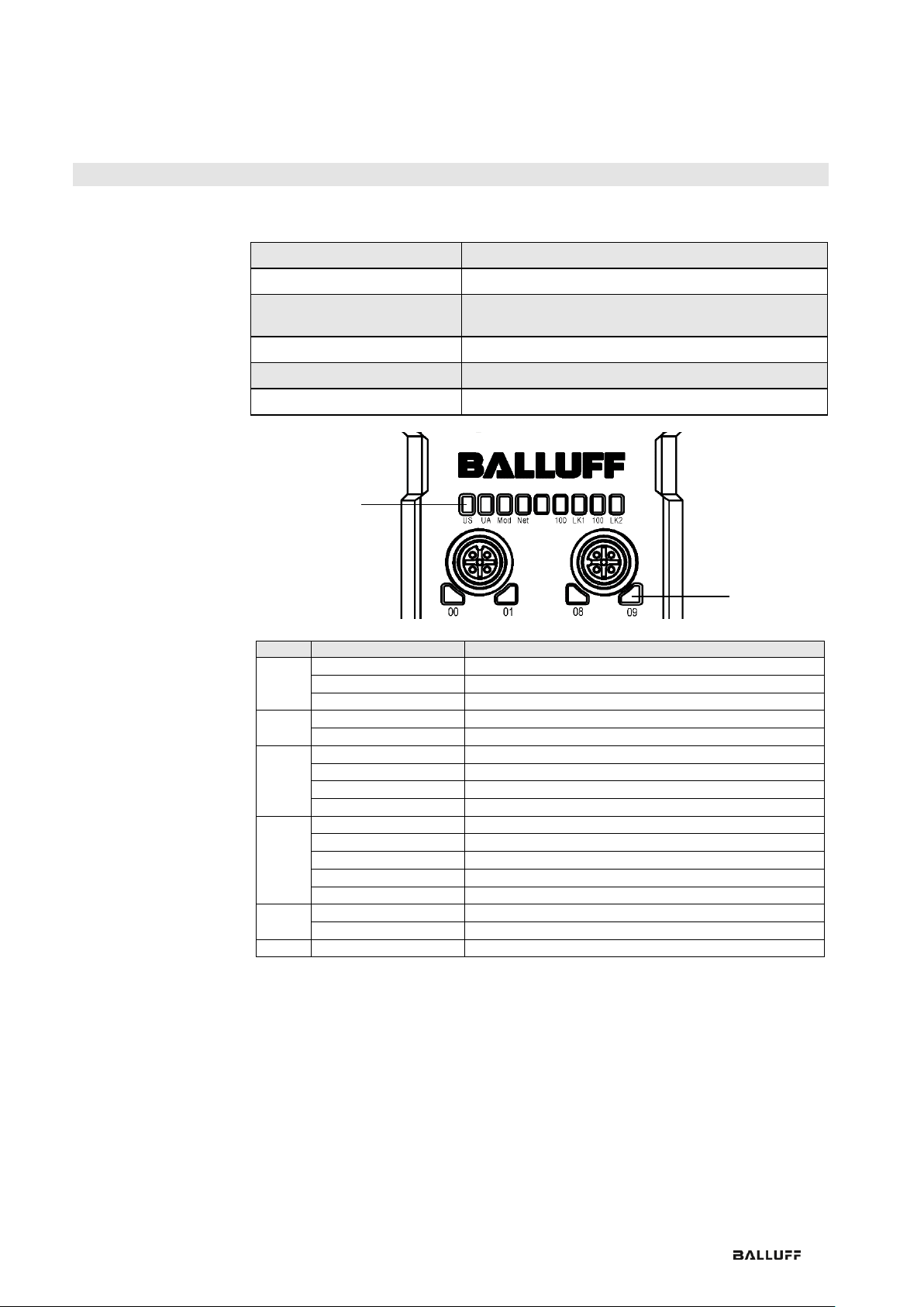
3.1. Module Overview
Figure – Overview: BNI EIP-508-105-R015
1 Mounting hole
2 EtherNet/IP™ port 2
3 Display
4 Power supply, input
5 Status LED: communication / module
6 Port 08 / 09 (IO-Link, standard I/O)
7 Pin/port LED: signal status
8 Port 10 / 11 (IO-Link, standard I/O)
9 Port 12 / 13 (IO-Link, standard I/O)
10 Port 14 / 15 (IO-Link, standard I/O)
11 Port 06 / 07 (IO-Link, standard I/O)
12 Port 04 / 05 (IO-Link, standard I/O)
13 Port 02 / 03 (IO-Link, standard I/O)
14 Port 00 / 01 (IO-Link, standard I/O)
15 Power supply, output
16 EtherNet/IP™ port 1
17 Ground connection
1 6 2 3 12
11
13
14
15
17
8
10
7 9 16 5 4
1

Balluff Network Interface EtherNet/IP™
www.balluff.com
6
3 First Steps
3.2. Mechanical
Connection
The module is secured by means of two M6 screws and two washers.
Insulation support is available separately.
3.3. Electrical
Connection
Power Supply
IN
7/8”, male
OUT
7/8” female
Pin
Function
Description
1
+24 V
Actuator supply
2
+24 V
Module / sensor supply
3
0 V
GND module / sensor and actuator supply
4
Note
Where possible, use a separate power source to supply the sensor/bus and
actuator with power.
Total current < 9 A The total current of all modules must not exceed 9 A even in
the case of series connection of the actuator supply.
Grounding
Note
The functional ground connection between housing and machine must have a
low impedance and be as short as possible.
Ethernet IP
Interface
M12, D-coded, female
Pin
Function
1
Tx+
Transmit Data +
2
Rx+
Receive Data +
3
Tx-
Transmit Data -
4
Rx-
Receive Data -

www.balluff.com
7
3 First Steps
I/O Port
M12, A-coded, female
Pin
Function
1
+24 V, 200 mA
2
Input/output 2A
3
GND
4
Input/output 2A
5
FE
Note
For the digital sensor inputs, refer to guideline on inputs EN 61131-2, Type 2.
Note
The total current of the module must not exceed 9 A.
Note
Unused I/O ports must be provided with cover caps to comply with degree of
protection IP67.
IO-Link Port
M12, A-coded, female
Pin
Function
1
+24 V, 1.6 A
2
Input/output 2A
3
GND
4
IO-Link/input/output 2A
5
n.a.
Port
Port
00/01, 02/03, 08/09, 10/11
04/05, 06/07, 12/13, 14/15
BNI EIP-502-105-R015
IN / OUT
IN / OUT / IO-Link
BNI EIP-508-105-R015
IN / OUT / IO-Link

Balluff Network Interface EtherNet/IP™
www.balluff.com
8
4 Technical Data
4.1. Dimensions
4.2. Mechanical Data
Housing material
Plastic housing, resistant (Fortron 6165 A6 black)
Enclosure rating per IEC 60529
IP 67 (only when plugged-in and threaded-in)
Supply voltage
7/8" 4-pin, connector / female
Input ports / output ports
M12, A-coded (8x female)
Dimensions (W x H x D in mm)
68 x 226 x 42.9
Type of mounting
Screw mounting with 2 mounting holes
Ground strap installation
M4
Weight
Approx. 670 gr.
4.3. Operating
Conditions
Operating temperature T
a
Storage temperature
-5 °C ... 70 °C
-25 °C ... 70 °C
EMC
- Immunity
- Emission
EMC Directive 2004/108/EEC
- EN 61000-6-2
- EN 61000-6-4
Shock/vibration
EN 60068-2-6, EN 60068-2-27
EN 60068-2-29, EN 60068-2-64
4.4. Electrical Data
Supply voltage
18...30.2 V DC, in accordance with EN 61131-2
Ripple
< 1%
Input current at 24 V
130 mA
www.balluff.com
9
4 Technical Data
4.5. Ethernet
Ethernet IP port
2 x 10Base/100Base Tx
Connection for Ethernet IP port
M12, D-coded, female
Cable types in accordance with
IEEE 802.3
Shielded, twisted pair min. STP CAT 5/ STP CAT 5e
Data transmission rate
10/100 Mbps
Max. cable length
100 m
Flow control
Half-duplex/full-duplex (IEEE 802.33x pause)
4.6. Function
Indicators
Module Status
LED
Display
Description
UA
Green
Output power OK
Red, flashing
Low output power (< 18V)
Red
No output power (< 11V)
US
Green
Input power OK
Red, flashing
Low input power (< 18V)
Mod
Green, flashing
Incorrect or no configuration of the module
Green
Module is working
Red, flashing
Fixed bus clock is not possible
Red-green, flashing
Initial sequence
Netw
ork
Off
Module has no IP address
Green, flashing
Module has IP, but no connection established
Green
Connection established
Red, flashing
Connection timeout
Red-green, flashing
Initial sequence
100
Off
Bus clock: 10 Mbps
Yellow
Bus clock: 100 Mbps
LNK
Green
Data transfer
Status LEDs
Port LEDs

Balluff Network Interface EtherNet/IP™
www.balluff.com
10
4 Technical Data
Port
Each port has two bicolored LEDs for displaying the I/O statuses.
Display
Status
Description
I/O port
Off
I/O status
The status of the input or output pins is 0
Yellow
I/O status
The status of the input or output pins is 1
Red,
flashing
Short-circuit
Short-circuit between pin 1 and 3
Red
Short-circuit
Short-circuit at dedicated pin
IO-Link port
Green
IO-Link
IO-Link communication active
Green,
flashing
IO-Link
No IO-Link communication
Green,
rapidly
flashing
IO-Link
IO-Link pre-operate during data storage
Red
Short-circuit
Short-circuit at pin 4
Red,
flashing
quickly
IO-Link
Validation failed /
Data storage failed /
Wrong device for data storage

www.balluff.com
11
5 Integration
5.1. Integration in
Rockwell RS
Logix 5000
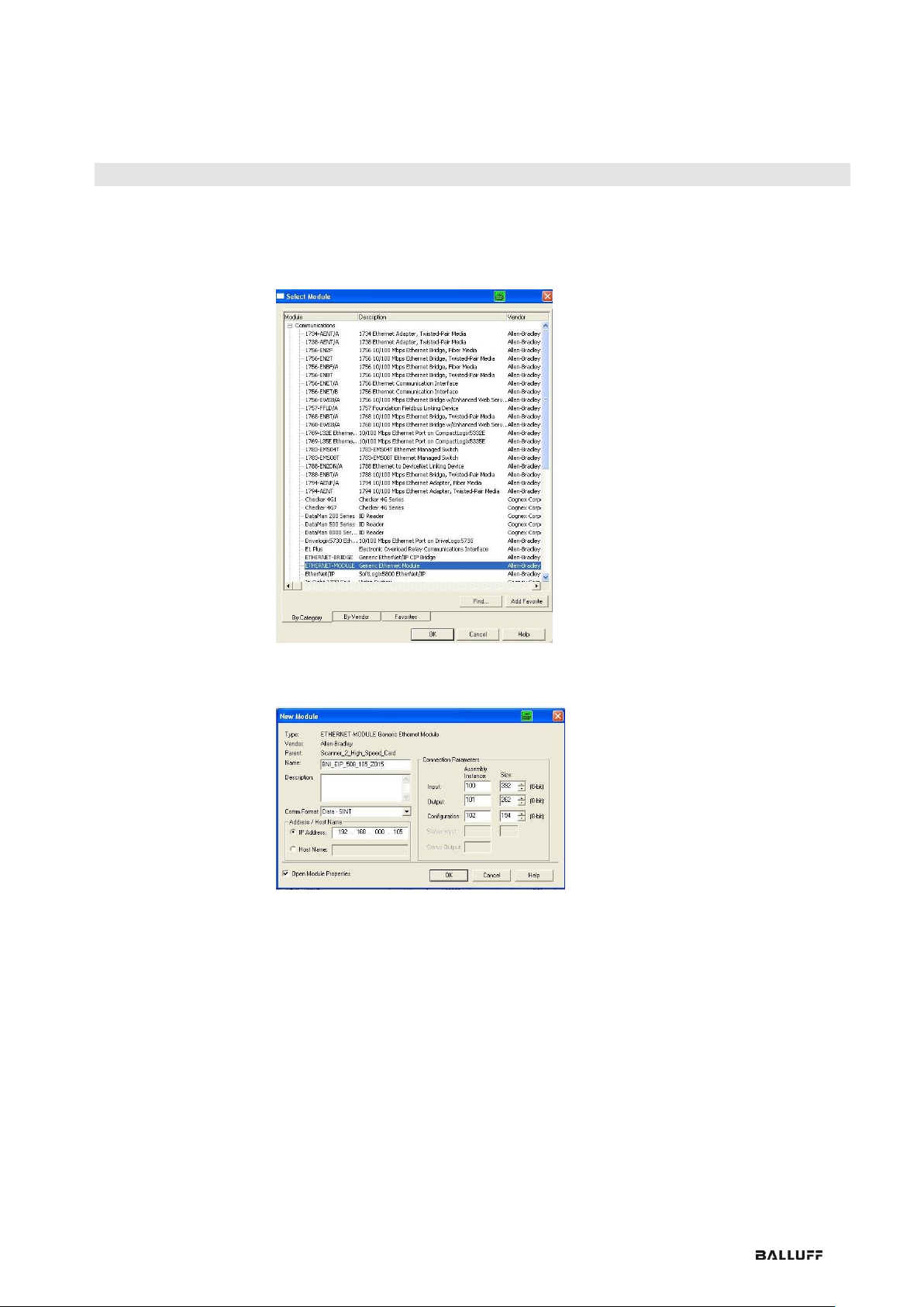
Here you see an example of how the module can be integrated into a Rockwell RS Logix
5000:
First go offline
Right-click Ethernet (on the correct scanner card)
Select a new module
Balluff Network Interface EtherNet/IP™
www.balluff.com
12
5 Integration
Then select the general Ethernet module as the ETHERNET module in the communication
path
Now enter a user-defined tag name to select the general format Data-SINT, to enter the IP
address of the module and to enter the correct connection parameters.
www.balluff.com
13
5 Integration
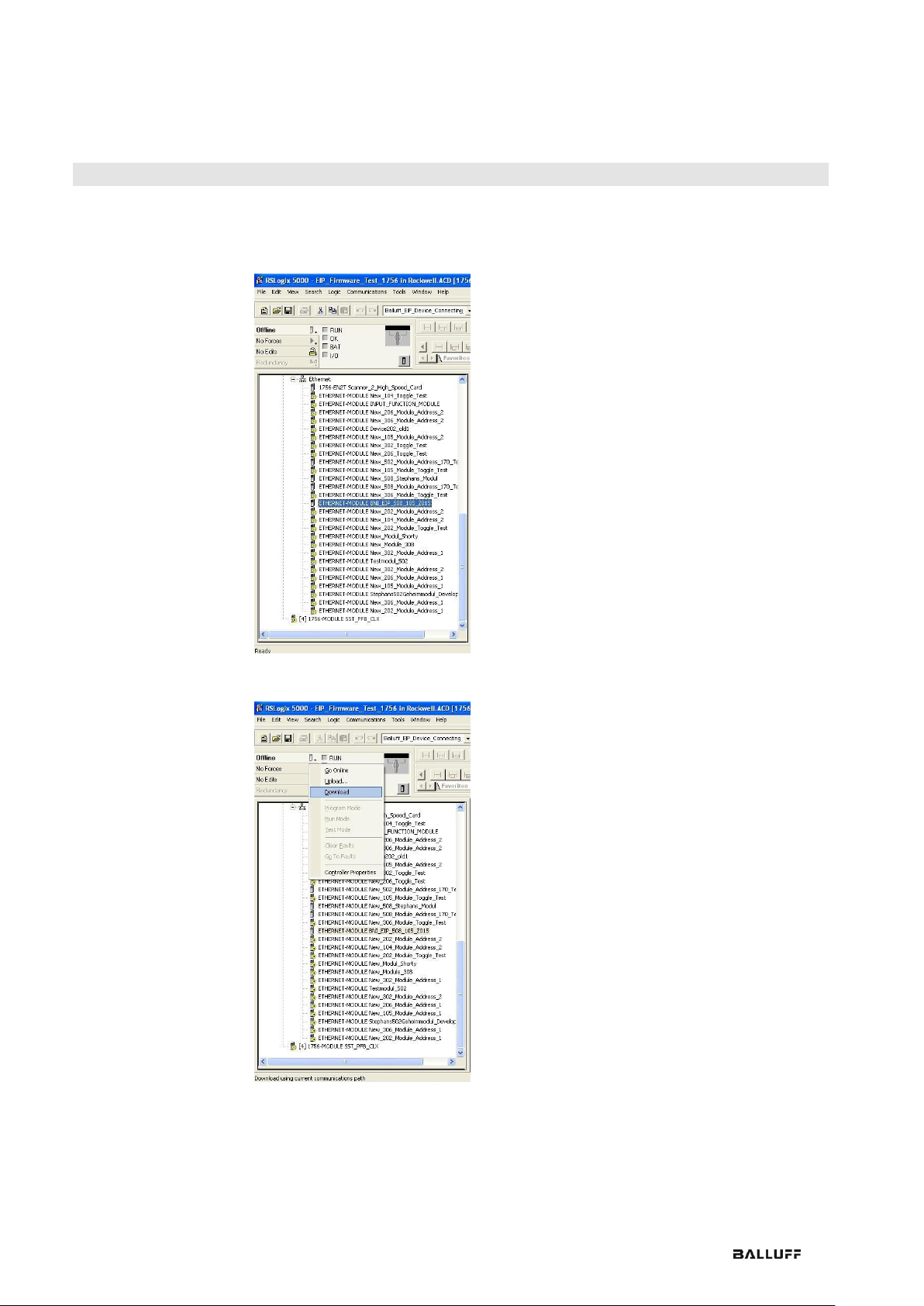
The new module and corresponding controller tags are generated automatically.
Then download the configuration
Balluff Network Interface EtherNet/IP™
www.balluff.com
14
5 Integration
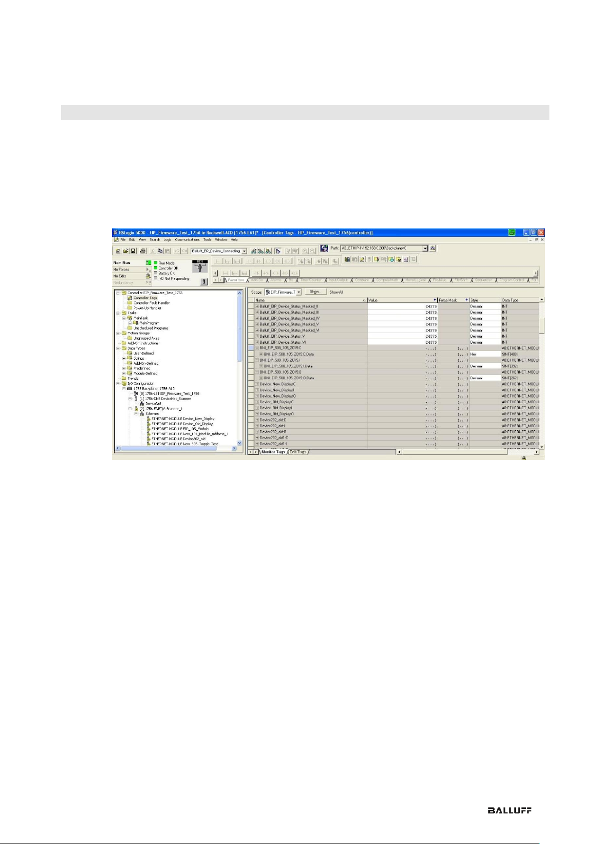
When the download is done, you can observe and control the tags using the Controller Tags option. Make
sure you select the correct tag name, which you configured beforehand.
The input, output and configuration data for this is described on the following pages.
You can use these tags for the programming, too.

www.balluff.com
15
5 Integration
5.2. Address
Specifications
These settings are factory-set.
IP-Adresse: 192.168.1.1
Subnetmaske: 255.255.255.0
Gatewayadresse: 192.168.1.1
5.3. Data
Configuration
Please enter the following values in the control system. They describe the data sizes of the
input, output and configuration data.
Instanc ID
Data length
502
508
507
527
508-C06
Input
100
200
392
196
196
128
Output
101
134
262
130
128
86
CONFIG
102
98
194
98
98
0
5.4. Configuration
Data
The following tables show an allocation of the configuration data sequence. The standard
values specified below describe a configuration with the IO-Link function at Pin 4 and
standard I/O functions at Pin 2 and 4 of each port. The input and output functions of the
configured standard I/O ports are set via the process data.
BNI EIP-502-105-XXXX, BNI EIP-507-005-Z040, BNI EIP-527-005-Z040
Byte
Slot
Module part
Description
0…1
1
Module
General configuration for the entire module
2…25
2
IO-Link port 0
Configuration of IO-Link port 0
26…49
3
IO-Link port 1
Configuration of IO-Link port 1
50…73
4
IO-Link port 2
Configuration of IO-Link port 2
74…97
5
IO-Link port 3
Configuration of IO-Link port 3
BNI EIP-508-105-XXXX
Byte
Slot
Module part
Description
0…1
1
Module
General configuration for the entire module
2…25
2
IO-Link port 0
Configuration of IO-Link port 0
26…49
3
IO-Link port 1
Configuration of IO-Link port 1
50…73
4
IO-Link port 2
Configuration of IO-Link port 2
74…97
5
IO-Link port 3
Configuration of IO-Link port 3
98…121
6
IO-Link port 4
Configuration of IO-Link port 4
122…145
7
IO-Link port 5
Configuration of IO-Link port 5
146…169
8
IO-Link port 6
Configuration of IO-Link port 6
170…193
9
IO-Link port 7
Configuration of IO-Link port 7
Note
The BNI EIP-508-XXX-XXXX-C06 has no configuration data. These are fixed
and can not be changed.

Balluff Network Interface EtherNet/IP™
www.balluff.com
16
5 Integration
Module
Configuration
BNI EIP-502-105XXX
Byte
Bit
Description
7 6 5 4 3 2 1
0
0
P3
P2 - -
Port function
0x00: Standard I/O
0x01: IO-Link
1
P7
P6 - -
Module
Configuration
BNI EIP-508-105XXX
Byte
Bit
Description
7 6 5 4 3 2 1
0
0
P3
P2
P1
P0
Port function
0x00: Standard I/O
0x01: IO-Link
1
P7
P6
P5
P4
Module
Configuration
BNI EIP-507-005Z040, BNI EIP527-005-Z040
Byte
Bit
Description
7 6 5 4 3 2 1
0
0
P3
P2
P1
P0
Port function
0x00: Standard I/O
0x01: IO-Link
1
Reserved
Module
Configuration BNI
EIP-508-XXXXXXX-C06
The IO-Link ports are always activated.
 Loading...