

Baldor VS1SM, VS1SM80P5, VS1SM81, VS1SM82 Installation & Operating Manual

Installation & Operating Manual
VS1SM
Single Phase AC Drive
10/07 MN761

Any trademarks used in this manual are the property of their respective owners.
Important:
Be sure to check www.baldor.com for the latest software, firmware and drivers for your
VS1 product. Also, you can download the latest version of this manual in Adobe Acrobat
PDF format.

Table of Contents
MN761 Table of Contents i
Chapter 1
Introduction 1-1. . . . . . . . . . . . . . . . . . . . . . . . . . . . . . . . . . . . . . . . . . . . . . . . . . . . . . . . . . . . .
1.1 Getting Assistance from Baldor 1-1. . . . . . . . . . . . . . . . . . . . . . . . . . . . . . . . . . . . . .
1.2 Safety Notice 1-1. . . . . . . . . . . . . . . . . . . . . . . . . . . . . . . . . . . . . . . . . . . . . . . . . . .
1.3 Quick Start 1-3. . . . . . . . . . . . . . . . . . . . . . . . . . . . . . . . . . . . . . . . . . . . . . . . . . . . .
Chapter 2
General Information and Ratings 2-1. . . . . . . . . . . . . . . . . . . . . . . . . . . . . . . . . . . . . . . . . . . . .
2.1 Identify the Drive by Model Number 2-1. . . . . . . . . . . . . . . . . . . . . . . . . . . . . . . . . . .
2.2 Storage Guidelines 2-1. . . . . . . . . . . . . . . . . . . . . . . . . . . . . . . . . . . . . . . . . . . . . . .
2.3 VS1SM Ratings, Model Numbers and Frame Sizes 2-1. . . . . . . . . . . . . . . . . . . . . . . .
Chapter 3
Installing the Drive 3-1. . . . . . . . . . . . . . . . . . . . . . . . . . . . . . . . . . . . . . . . . . . . . . . . . . . . . . . .
3.1 Receiving & Inspection 3-1. . . . . . . . . . . . . . . . . . . . . . . . . . . . . . . . . . . . . . . . . . . .
3.2 General Requirements for the Installation Site 3-1. . . . . . . . . . . . . . . . . . . . . . . . . . . .
3.2.1 Operating Conditions 3-1. . . . . . . . . . . . . . . . . . . . . . . . . . . . . . . . . . . . . . . . .
3.2.2 Minimum Mounting Clearances 3-1. . . . . . . . . . . . . . . . . . . . . . . . . . . . . . . . . .
3.3 Mounting the Drive 3-1. . . . . . . . . . . . . . . . . . . . . . . . . . . . . . . . . . . . . . . . . . . . . . .
3.3.1 Protecting the Drive from Debris 3-1. . . . . . . . . . . . . . . . . . . . . . . . . . . . . . . . .
3.3.2 Watts Loss Data 3-2. . . . . . . . . . . . . . . . . . . . . . . . . . . . . . . . . . . . . . . . . . . .
3.3 Cover Removal 3-2. . . . . . . . . . . . . . . . . . . . . . . . . . . . . . . . . . . . . . . . . . . . . . . . .
Chapter 4
Power Wiring 4-1. . . . . . . . . . . . . . . . . . . . . . . . . . . . . . . . . . . . . . . . . . . . . . . . . . . . . . . . . . . .
4.1 Overview of Power Connections 4-1. . . . . . . . . . . . . . . . . . . . . . . . . . . . . . . . . . . . . .
4.2 Power Disconnect 4-2. . . . . . . . . . . . . . . . . . . . . . . . . . . . . . . . . . . . . . . . . . . . . . . .
4.3 Protective Devices 4-2. . . . . . . . . . . . . . . . . . . . . . . . . . . . . . . . . . . . . . . . . . . . . . .
4.4 Electrical Installation 4-2. . . . . . . . . . . . . . . . . . . . . . . . . . . . . . . . . . . . . . . . . . . . . .
4.4.1 Input Power Connections 4-2. . . . . . . . . . . . . . . . . . . . . . . . . . . . . . . . . . . . . .
4.4.1 Grounding Procedure 4-4. . . . . . . . . . . . . . . . . . . . . . . . . . . . . . . . . . . . . . . .
4.4.2 Motor Connections 4-4. . . . . . . . . . . . . . . . . . . . . . . . . . . . . . . . . . . . . . . . . .
4.5 Optional Dynamic Brake Hardware 4-4. . . . . . . . . . . . . . . . . . . . . . . . . . . . . . . . . . . .
Chapter 5
Control Wiring 5-1. . . . . . . . . . . . . . . . . . . . . . . . . . . . . . . . . . . . . . . . . . . . . . . . . . . . . . . . . . .
5.1 Control Wiring Overview 5-1. . . . . . . . . . . . . . . . . . . . . . . . . . . . . . . . . . . . . . . . . . .
5.2 Control Input Connections 5-2. . . . . . . . . . . . . . . . . . . . . . . . . . . . . . . . . . . . . . . . . .
5.3 Control Output Connections 5-4. . . . . . . . . . . . . . . . . . . . . . . . . . . . . . . . . . . . . . . . .
Chapter 6
Using the Keypad 6-1. . . . . . . . . . . . . . . . . . . . . . . . . . . . . . . . . . . . . . . . . . . . . . . . . . . . . . . .
6.1 Keypad Overview 6-1. . . . . . . . . . . . . . . . . . . . . . . . . . . . . . . . . . . . . . . . . . . . . . . .
6.2 Parameter Groups 6-2. . . . . . . . . . . . . . . . . . . . . . . . . . . . . . . . . . . . . . . . . . . . . . .
Chapter 7
Parameter Descriptions 7-1. . . . . . . . . . . . . . . . . . . . . . . . . . . . . . . . . . . . . . . . . . . . . . . . . . . .
7.1 Drive Group 7-1. . . . . . . . . . . . . . . . . . . . . . . . . . . . . . . . . . . . . . . . . . . . . . . . . . . .
7.2 Function Group1 7-3. . . . . . . . . . . . . . . . . . . . . . . . . . . . . . . . . . . . . . . . . . . . . . . . .
7.3 Function Group2 7-10. . . . . . . . . . . . . . . . . . . . . . . . . . . . . . . . . . . . . . . . . . . . . . . . .
7.4 I/O Group 7-19. . . . . . . . . . . . . . . . . . . . . . . . . . . . . . . . . . . . . . . . . . . . . . . . . . . . .

ii Table of Contents MN761
Chapter 8
Customizing for Your Application 8-1. . . . . . . . . . . . . . . . . . . . . . . . . . . . . . . . . . . . . . . . . . . .
Chapter 9
Troubleshooting 9-1. . . . . . . . . . . . . . . . . . . . . . . . . . . . . . . . . . . . . . . . . . . . . . . . . . . . . . . . .
9.1 Periodic Maintenance 9-1. . . . . . . . . . . . . . . . . . . . . . . . . . . . . . . . . . . . . . . . . . . . .
9.2 Reviewing Fault Status of the Drive 9-1. . . . . . . . . . . . . . . . . . . . . . . . . . . . . . . . . . .
Appendix A
Technical Specifications A-1. . . . . . . . . . . . . . . . . . . . . . . . . . . . . . . . . . . . . . . . . . . . . . . . . . .
Appendix B
Parameter Tables B-1. . . . . . . . . . . . . . . . . . . . . . . . . . . . . . . . . . . . . . . . . . . . . . . . . . . . . . . . .
Appendix C
CE Guidelines C-1. . . . . . . . . . . . . . . . . . . . . . . . . . . . . . . . . . . . . . . . . . . . . . . . . . . . . . . . . . .
C.1 CE Declaration of Conformity C-1. . . . . . . . . . . . . . . . . . . . . . . . . . . . . . . . . . . . . . . .
C.2 EMC - Conformity and CE - Marking C-1. . . . . . . . . . . . . . . . . . . . . . . . . . . . . . . . . .
C.3 EMC Installation Instructions C-4. . . . . . . . . . . . . . . . . . . . . . . . . . . . . . . . . . . . . . .

MN760 Quick Start 1-1
Chapter 1
Introduction
This manual is intended for qualified electrical personnel familiar with installing, programming, and
maintaining AC Drives. This manual contains information on:
S Installing and wiring the VS1SM drive
S Programming the drive
S Troubleshooting the drive
1.1 Getting Assistance from Baldor
For technical assistance, contact your Baldor District Office. Before calling, please review the
troubleshooting section of this manual and you will be asked for the drive model number or catalog
number that is located on the Nameplate.
1.2 Safety Notice
This equipment contains voltages that may be as high as 1000 volts! Electrical shock can cause serious
or fatal injury. Only qualified personnel should attempt the start-up procedure or troubleshoot this
equipment.
This equipment may be connected to other machines that have rotating parts or parts that are driven by
this equipment. Improper use can cause serious or fatal injury. Only qualified personnel should attempt
the start-up procedure or troubleshoot this equipment.
Precautions: Classifications of cautionary statements
WARNING: Do not touch any circuit board, power device or electrical connection before you first
ensure that power has been disconnected and there is no high voltage present from
this equipment or other equipment to which it is connected. Electrical shock can
cause serious or fatal injury. Only qualified personnel should attempt the start-up
procedure or troubleshoot this equipment.
WARNING: Be sure that you are completely familiar with the safe operation of this equipment.
This equipment may be connected to other machines that have rotating parts or
parts that are controlled by this equipment. Improper use can cause serious or fatal
injury. Only qualified personnel should attempt the start-up procedure or
troubleshoot this equipment.
WARNING: Do not use motor overload relays with an automatic reset feature. These are
dangerous since the process may injure someone if a sudden or unexpected
automatic restart occurs. If manual reset relays are not available, disable the
automatic restart feature using external control wiring.
WARNING: This unit has an automatic restart feature that will start the motor whenever input
power is applied and a RUN (FWD or REV) command is issued. If an automatic restart
of the motor could cause injury to personnel, the automatic restart feature of the
VS1MSD should be disabled.
WARNING: Be sure the system is properly grounded before applying power. Do not apply AC
power before you ensure that all grounding instructions have been followed.
Electrical shock can cause serious or fatal injury.
WARNING: Do not remove cover for at least five (5) minutes after AC power is disconnected to
allow capacitors to discharge. Dangerous voltages are present inside the equipment.
Electrical shock can cause serious or fatal injury.
WARNING: Motor circuit may have high voltage present whenever AC power is applied, even
when motor is not rotating. Electrical shock can cause serious or fatal injury.
Continued on next page

1-2 Quick Start MN760
WARNING: Improper operation of control may cause violent motion of the motor shaft and
driven
equipment. Be certain that unexpected motor shaft movement will not cause injury to
personnel or damage to equipment. Certain failure modes of the control can produce
peak torque of several times the rated motor torque.
WARNING: Dynamic brake resistors may generate enough heat to ignite combustible materials.
Keep all combustible materials and flammable vapors away from brake resistors.
WARNING: The motor shaft will rotate during the autotune procedure. Be certain that
unexpected motor shaft movement will not cause injury to personnel or damage to
equipment.
Caution: Disconnect motor leads (U, V and W) from control before you perform a “Dielectric
Withstand” test on the motor. Failure to disconnect motor from the control will result
in extensive damage to the control. The control is tested at the factory for high
voltage / leakage resistance as part of Underwriter Laboratory requirements.
Caution: Suitable for use on a circuit capable of delivering not more than the RMS
symmetrical short circuit amperes listed here at rated voltage.
Horsepower
RMS Symmetrical Amperes
1-50 5,000
51-200 10,000
201-400 18,000
401-600 30,000
601-900 42,000
Caution: Do not connect AC power to the Motor terminals U, V and W. Connecting AC power
to these terminals may result in damage to the control.
Caution: Baldor recommends not to use “Grounded Leg Delta” transformer power leads that
may create ground loops. Instead, we recommend using a four wire Wye.
Caution: If the DB hardware mounting is in any position other than vertical, the DB hardware
must be derated by 35% of its rated capacity.
Caution: Only Baldor cables should be used to connect the keypad and control. These are
special twisted pair cables to protect the control and keypad. Damage associated
with other cable types are not covered by the Baldor warranty.
Caution: If an M-Contactor is installed, the control must be disabled for at least 200msec
before the M-Contactor is opened. If the M-Contactor is opened while the control is
supplying voltage and current to the motor, the control may be damaged. Before the
control is enabled, the M-Contactor must be closed for at least 200msec.
Caution: Use of power correction capacitors on the output of the drive can result in erratic
operation of the motor, nuisance tripping, and/or permanent damage to the drive.
Remove power correction capacitors before proceeding. Failure to observe this
precaution could result in damage to, or destruction of, the equipment.
MN760 Quick Start 1-3
1.3 Quick Start Quick Start Guide is also available separately, see MS760.
Figure 1‐1 Power & Motor Terminal Locations
L1 L2 P P1 N U V W
Jumper Bar
VS1SM82/82-F, VS1SM83/83-F
L1 L2 P P1 N
UVW
Jumper Bar
VS1SM80P5/80P5-F, VS1SM81/81-F
Powerup Procedure Refer to Chapter 3, 4 and 5 for additional details.
1. Remove all power from the control.
2. Connect Power & Motor, See Figure 1‐1.
3. Connect input control wires and output wires, See Figure 1‐2.
4. Disconnect the motor from the load (including coupling or inertia wheels).
5. Turn power on. Be sure there are no faults.
6. Set the following parameters for the values displayed on the motor nameplate:
P30 Motor HP Select
P32 Motor Rated Current
P33 Pole Number
P34 Base Frequency
7. If external dynamic brake hardware is used, set the Level 2 Brake Adjust block “Resistor Ohms”
and “Resistor Watts” parameters.
WARNING: The motor shaft will rotate during this procedure. Be certain that unexpected motor
shaft movement will not cause injury to personnel or damage to equipment.
8. Set H41 =1 from using the Keypad. Perform each step including auto tune.
9. Remove all power from the control.
10. Couple the motor to its load.
11. Verify freedom of motion of motor shaft.
12. Verify the motor coupling is tight without backlash.
13. Verify the holding brakes if any, are properly adjusted to fully release and set to the desired torque.
14. Turn power on. Be sure no errors are displayed.
15. Run the drive from the keypad.
16. Select and program additional parameters to suit your application, see Chapter 8.
The control is now ready for use the in keypad mode. If a different operating mode is desired, refer to
Chapter 7 Parameter Descriptions and Chapter 8 Customizing for your Application.
1-4 Quick Start MN760
Figure 1‐2 Input/Output Connections
Control I/O Terminal Strip
P4
P5 VR V1 CM I AM
30A30B30C MOEXTGP24 P1 P2 CM P3
See MN761 for
Tightening Torques
NP
N
PN
P
Set the NPN/PNP switch
for desired mode.
NPN Mode
PNP Mode
OR
Shown with NPN Digital Input Connections
Tightening Torque = 3.5 lb-in (0.4Nm)
Forward Run
Speed signal input (0-10VDC )
Speed signal input (0-20mA)
P1
P2
P3
P4
P5
P24
VR
VI
I
CM
Reverse Run
Output Inhibit
Jog Operation
Fault Reset
PNP 24VDC Output
Common
VS1SM
Digital
Inputs
AM
CM
30A
30B
30C
MO
EXTG
Relay Output
Digital Output
Analog Output
(0-10VDC)
Tightening Torque =
3.5 lb-in (0.4Nm)
MN761 General Information and Ratings 2-1
Chapter 2
General Information and Ratings
The VS1SM is a variable frequency PWM drive capable of operating in open- loop, V/Hz (volts per
hertz) mode and in a sensorless vector control (SVC) mode. This chapter contains information
about the VS1SM drive, including how to identify the drive.
2.1 Identify the Drive by Model Number
Each drive can be identified by its model number, as shown in Figure 2‐1. The model number is on
the shipping label and the drive nameplate. The model number includes the drive and any options.
Figure 2‐1 Drive Identification
VS1 family SM (Sub-Micro)
for Single Phase Power Applications
VS1 SM 8 0P5
Voltage Code
8= 230VAC, 1PH
Horse Power Rating
OP5=0.5HP
1 = 1HP
2 = 2HP
3 = 3HP
V/Hz and Open Loop Vector Control -F
EMC Filter:
F = Filter
blank = No Filter
2.2 Storage Guidelines
If you need to store the drive, follow these recommendations to prolong drive life and performance:
1. Storage ambient temperature is -20°C to 65°C.
2. Storage Humidity range 10% to 90% RH non-condensing.
3. Do not expose to corrosive atmosphere.
2.3 VS1SM Ratings, Model Numbers and Frame Sizes
Table 2‐1 has drive ratings for each VS1SM Model.
Table 2‐1
Catalog No.
Input
Volt
Frame
Size
Output Watts Loss
HP KW Amps Watts
VS1SM80P5 230 A 0.5 0.4 2.5 7
VS1SM81 230 A 1 0.75 5.0 25
VS1SM82 230 B 2 1.5 8.0 48
VS1SM83 230 B 3 2.2 12.0 73

2-2 General Information and Ratings MN761
MN761 Installing the Drive 3-1
Chapter 3
Installing the Drive
This chapter provides information that must be considered when planning a VS1SM drive
installation and provides drive mounting information and installation site requirements.
3.1 Receiving & Inspection
When you receive your control, there are several things you should do immediately.
1. Observe the condition of the shipping container and report any damage immediately to the
commercial carrier that delivered your control.
2. Remove the control from the shipping container and remove all packing materials from the control.
The container and packing materials may be retained for future shipment.
3. Verify that the part number of the control you received is the same as the part number listed on
your purchase order.
4. Inspect the control for external physical damage that may have been sustained during shipment
and report any damage immediately to the commercial carrier that delivered your control.
5. If the control is to be stored for several weeks before use, be sure that it is stored in a location that
conforms to published storage humidity and temperature specifications stated in this manual.
3.2 General Requirements for the Installation Site
It is important to ensure that the drives environment and operating conditions are satisfactory.
The area behind the drive must be kept clear of all control and power wiring. Power connections may
create electromagnetic fields that may interfere with control wiring or components when run in close
proximity to the drive.
Read the recommendations in the following sections before continuing with the drive installation.
3.2.1 Operating Conditions
Before deciding on an installation site, consider the following guidelines:
S Protect the cooling fan by avoiding dust or metallic particles.
S Do not expose the drive to a corrosive atmosphere.
S Protect the drive from moisture and direct sunlight.
S Verify that the drive location will meet the environmental conditions specified in Table 3‐1.
Table 3‐1 - Ambient Temperatures and Mounting Clearances
Ambient Temperature
Enclosure Rating Minimum Mounting Clearances
Minimum Maximum
14°F (-10°C)
104°F (40 °C) IP20/Open Type 2 in (50mm)
104°F (40 °C) IP20/NEMA 1 2 in (50mm)
104°F (40 °C) Side-by-Side 2 in (50mm)
3.2.2 Minimum Mounting Clearances
Be sure to provide proper top, bottom and side clearance (2” minimum each side).
3.3 Mounting the Drive
Mount the drive upright on a flat, vertical, non combustible and level surface.
Refer to Figure 3‐3 for mounting hole locations.
3.3.1 Protecting the Drive from Debris
The drive must be protected from debris falling through the drive vents during installation and operation.
The drive is designed to operate in IP20/NEMA1 Type installations.
3-2 Installing the Drive MN761
3.3.2 Watts Loss Data
Refer to Table 2‐1 for watts loss data.
3.3 Cover Removal
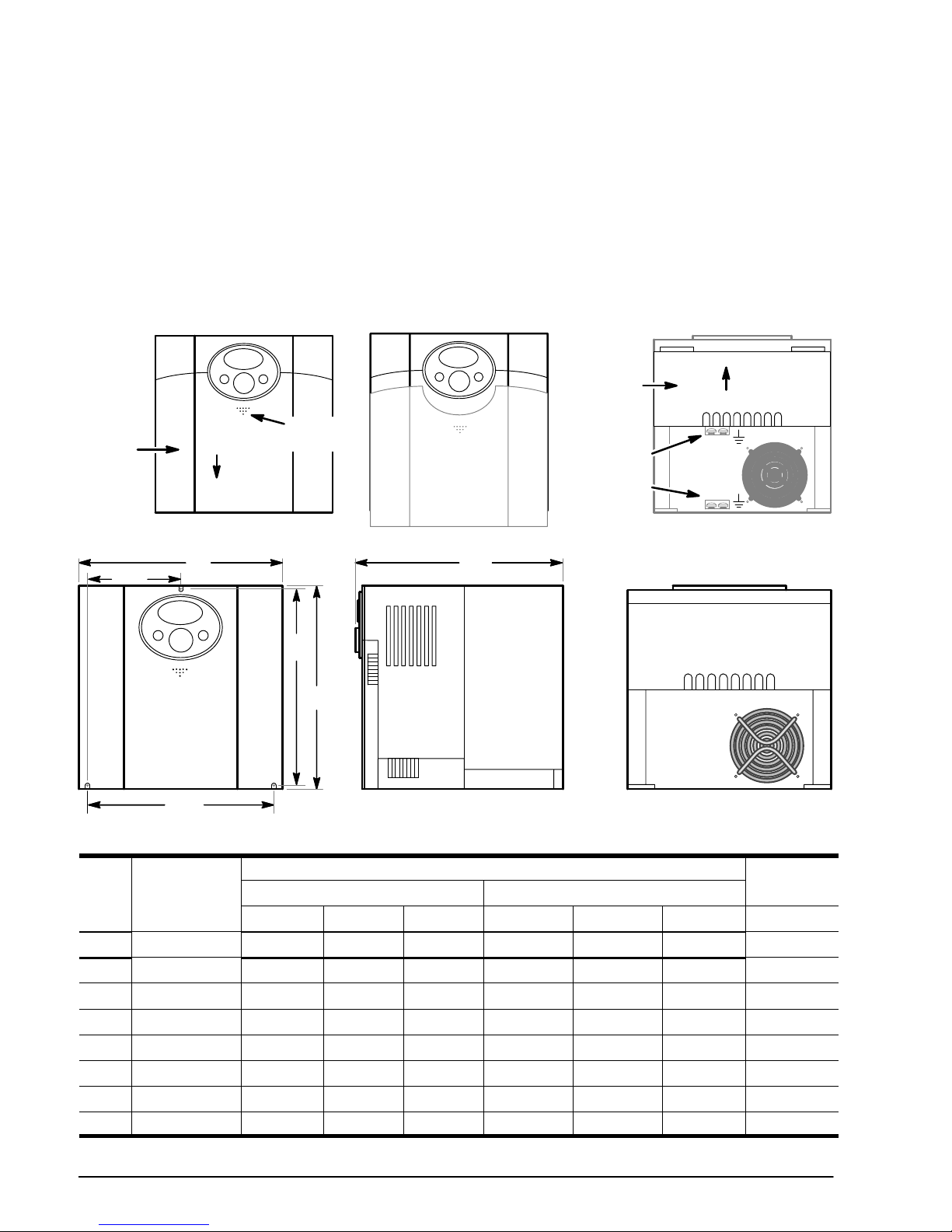
To connect power and signal wires, the cover must be removed.
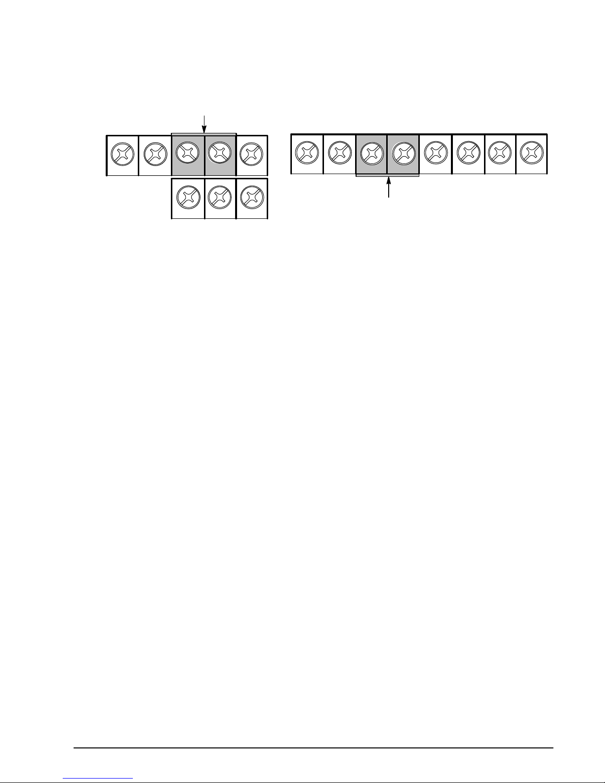
Remove the cover as shown in Figure 3‐2.
1. Gently press in the area labeled Cover Release shown in Figure 3‐2.
2. Slide the cover downward about 3/8 in (10mm) and lift off the Main Cover.
3. The Power Terminal Cover can then be removed by lifting it from the control.
Figure 3‐2 Cover Removal
Cover
Release
Main
Cover
Power
Terminal
Cover
Lift Cover
Slide
Cover
Power &
Motor
Ground
Size B
Size A
Figure 3‐3 Mounting Hole Locations
B1
B2
B
A1
A
C
Table 3‐2 Drive Dimensions and Weights
Size
Catalog
Number
Dimensions inches(mm)
Weight
Outside Mounting
Height (A) Width (B) Depth (C) Height (A1) Width (B1) Width (B2) lb (kg)
A VS1SM80P5 5.63 (143) 3.11 (79) 5.64 (143) 2.66 (67.5) 5.35(135.9) N/A 1.92 (0.87)
A VS1SM80P5- F 5.63 (143) 3.11 (79) 5.64 (143) 2.66 (67.5) 5.35(135.9) N/A 2.09(0.95)
A VS1SM81 5.63 (143) 3.11 (79) 5.64 (143) 2.66 (67.5) 5.35(135.9) N/A 1.96 (0.89)
A VS1SM81-F 5.63 (143) 3.11 (79) 5.64 (143) 2.66 (67.5) 5.35(135.9) N/A 2.14(0.97)
B VS1SM82 5.63 (143) 6.14 (156) 5.64 (143) 5.34 (135) 5.43 (138) 2.71 (68.8) 3.95 (1.79)
B VS1SM82-F 5.63 (143) 6.14 (156) 5.64 (143) 5.34 (135) 5.43 (138) 2.71 (68.8) 4.28(1.94)
B VS1SM83 5.63 (143) 6.14 (156) 5.64 (143) 5.34 (135) 5.43 (138) 2.71 (68.8) 4.08 (1.85)
B VS1SM83-F 5.63 (143) 6.14 (156) 5.64 (143) 5.34 (135) 5.43 (138) 2.71 (68.8) 4.41(2.0)
MN761 Power Wiring 4-1
Chapter 4
Power Wiring
4.1 Overview of Power Connections
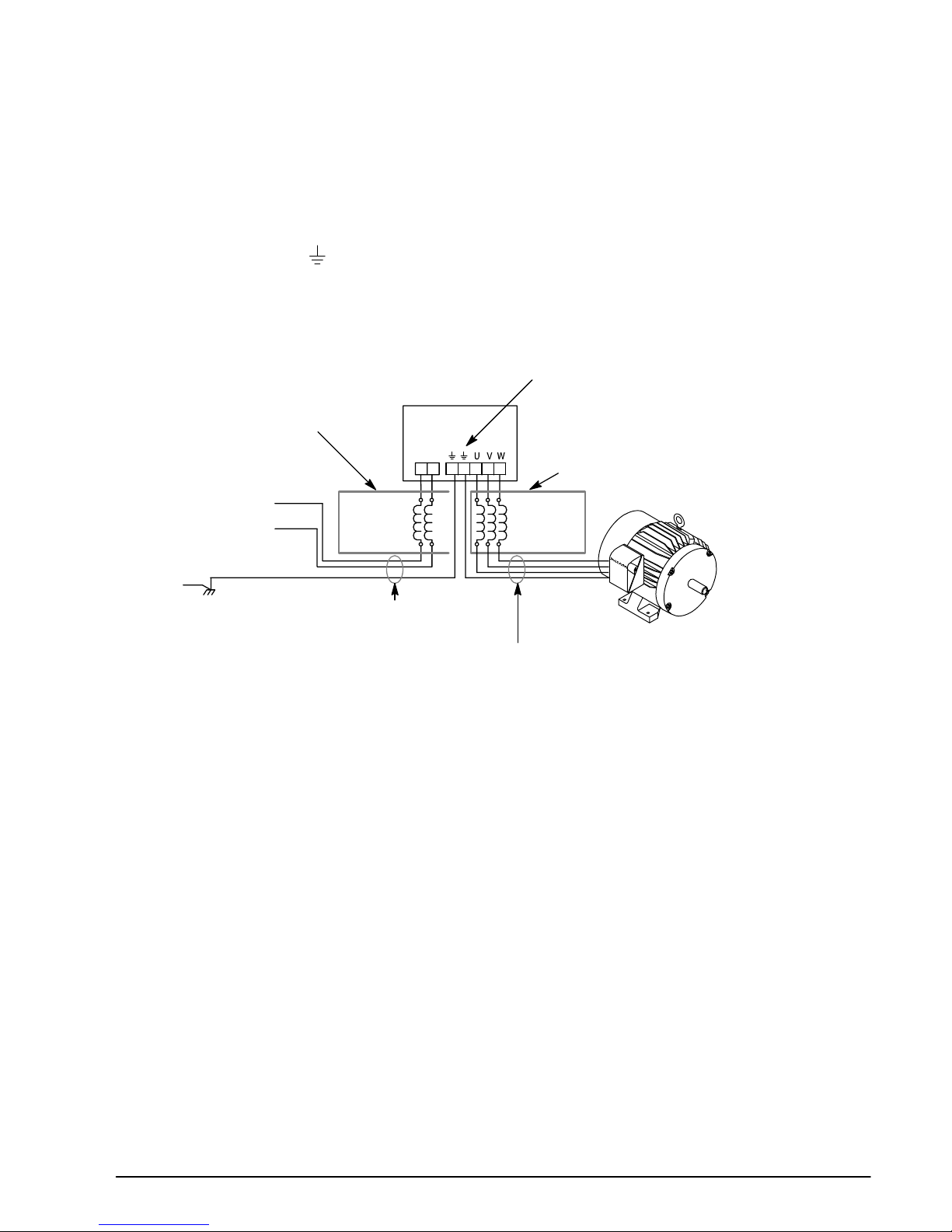
The recommended grounding method is shown in Figure 4‐1.
Safety Ground - (G)
This is the safety ground for the drive that is required by code. One of these points must be connected to
adjacent building steel (girder, joist), a floor ground rod, or bus bar. Grounding points must comply with
national and local industrial safety regulations and/or electrical codes.
Figure 4‐1 Recommended System Grounding
AC Main
Supply
Safety
Ground
Driven Earth
Ground Rod
(Plant Ground)
Four Wire
“Wye”
L1
L2
Optional
Line
Reactor
Optional
Load
Reactor
Route all 4 wires L1, L2, L3 and Earth
(Ground) together in conduit or cable.
Route all 4 wires U, V, W and Motor Ground together in conduit or cable.
Connect all wires (including motor ground) inside the motor terminal box.
Ground per NEC
and Local codes.
Note: Wiring shown for clarity of grounding
method only. Not representative of
actual terminal block location.
Note: A load reactor is recommended
and must be purchased separately.
Note: A line reactor is recommended and
must be purchased separately.
Drive
See recommended tightening torques in Table 4‐1.
L1
L2
Motor Ground
The motor ground must be connected to one of the ground terminals on the drive.
Shield Termination
Either of the safety ground terminals located on the power terminal block provides a grounding point for
the motor cable shield. The motor cable shield connected to one of these terminals (drive end) should
also be connected to the motor frame (motor end). Use a shield terminating or EMI clamp to connect the
shield to the safety ground terminal. The NEMA 1/IP30 Kit may be used with a cable clamp for a
grounding point for the cable shield.
When shielded cable is used for control and signal wiring, the shield should be grounded at the drive end
only, never at both ends.
RFI Filter Grounding
Using single-phase drives with integral filter, or an external filter with any drive rating, may result in
relatively high ground leakage currents. Therefore, the filter must only be used in installations with
grounded AC supply systems and be permanently installed and solidly grounded (bonded) to the building
power distribution ground.
Ensure that the incoming supply neutral is solidly connected (bonded) to the same building power
distribution ground. Grounding must not rely on flexible cables and should not include any form of plug or
socket that would permit inadvertent disconnection. Some local codes may require redundant ground
connections. The integrity of all connections should be checked periodically.

4-2 Power Wiring MN761
4.2 Power Disconnect
A power disconnect should be installed between the input power service and the drive for a fail safe
method to disconnect power. The drive will remain in a powered‐up condition until all input power is
removed from the drive and the internal bus voltage is depleted.
4.3 Protective Devices
Recommended fuse sizes are based on the following:
115% of maximum continuous current for time delay.
150% of maximum continuous current for Fast or Very Fast action.
Note: These recommendations do not consider harmonic currents or ambient temperatures greater than
45°C.
Be sure a suitable input power protection device is installed. Use the recommended fuses and wire sizes
shown in Table 4‐1 is based on the use of copper conductor wire rated at 75 °C. The table is specified
for NEMA B motors.
Fast Action Fuses: 240VAC, Buss® KTN; 460VAC, Buss® KTS
Very Fast Action: 240VAC, Buss® JJN; 460VAC, Buss® JJS
Semiconductor 240VAC, Ferraz Shawmut A50QS
Buss® is a trademark of Cooper Industries, Inc.
4.4 Electrical Installation
All interconnection wires between the drive, AC power source, motor, host control and any operator
interface stations should be in metal conduits or shielded cable must be used. Use listed closed loop
connectors that are of appropriate size for wire gauge being used. Connectors are to be installed using
crimp tool specified by the manufacturer of the connector. Only class 1 wiring should be used.
Table 4‐1 Fuse & Wire Size and Terminal Tightening Torque Specifications
Catalog Number
Input Fuse (Amps) Wire Gauge Tightening Torque
Fast Acting (UL) AWG mm
2
lb-in Nm
VS1SM80PF, VS1SM80P5-F 10A 14 2.5 9 4.5
VS1SM81, VS1SM81-F 20A 14 2.5 9 4.5
VS1SM82, VS1SM82-F 30A 12 4.0 15 1.7
VS1SM83, VS1SM83-F 40A 12 4.0 15 1.7
Note: Wire sizes based on 75°C copper wire. Fuses based on 45°C ambient, max continuous output and no
harmonic current.
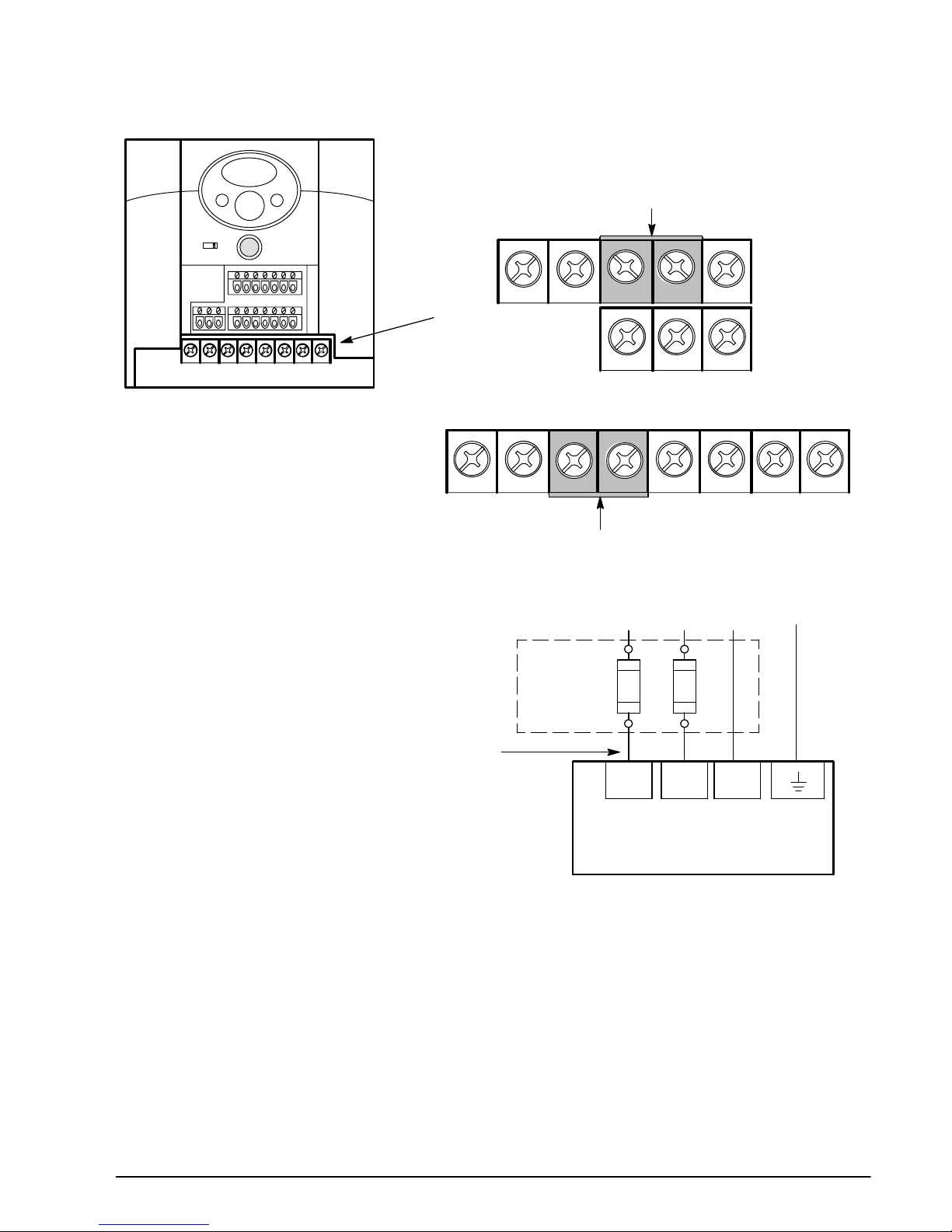
4.4.1 Input Power Connections
All cables must be shielded and the shields must be grounded at the enclosure cable entrance.
1. Connect the line L1, L2 to the Power Terminal Strip, Figure 4‐3.
2. Connect the motor leads to U, V and W terminals, Figure 4‐2.
3. Connect motor ground to the ground terminal located in the opening at the rear of the drive by
the fan (see Figure 3‐2 for location).
MN761 Power Wiring 4-3
Figure 4‐2 Power Terminal Locations
NPN
PNP
Power Terminal Strip
L1 L2 P P1 N U V W
Jumper Bar
VS1SM82/82-F, VS1SM83/83-F
L1 L2 P P1 N
UVW
Jumper Bar
VS1SM80P5/80P5-F, VS1SM81/81-F
See Recommended Tightening
Torques in table 4‐1.
Figure 4‐3 Input Power Connections
L1 L2
L1 L2
Earth
* Optional components not provided with control.
Baldor
Control
Note 1
Note 3
Notes:
1. See “Protective Devices” described
previously in this section.
2. Use same gauge wire for Earth ground
as is used for L1 and L2.
3. Metal conduit should be used. Connect
conduits so the use of a Reactor or RC
Device does not interrupt EMI/RFI
shielding.
Note 2
*Fuses
See Recommended Tightening Torques in table 4‐1.
See Figure 3‐2
for ground location.
N
N
4-4 Power Wiring MN761
Figure 4‐4 Motor Connections
* Optional components not
provided with control.
Baldor Control
Notes:
1. Metal conduit should be used. Connect
conduits so the use of Load Reactor or RC
Device does not interrupt EMI/RFI shielding.
2. See Line/Load Reactors described
previously in this section.
3. Use same gauge wire for ground as for U, V
and W.
* AC Motor
Note 1
*Optional
Load
Reactor
Note 1
A1 B1 C1
A2 B2 C2
UVW
U
VW
G
Note 3
Note 2
See Recommended Tightening
Torques in table 4‐1.
See Figure 3‐2 for ground location.
4.4.1 Grounding Procedure
1. Remove covers. Cover removal is described in Chapter 3 of this manual.
2. Connect the power ground wire to the ground terminal G (see Figure 3‐2).
3. Connect the motor ground wire to the ground terminal G (see Figure 3‐2).
4.4.2 Motor Connections
All cables must be shielded and the shields must be grounded at the enclosure cable entrance.
1. Remove covers. Cover removal is described in Chapter 3 of this manual.
2. Connect the Motor leads to terminals U, V and W (see Figure 4‐2 for location).
Long Motor Leads
The wire leads that connect the motor to the control are critical in terms of sizing, shielding and the cable
characteristics. Short cable runs are usually trouble free but fault-monitoring circuitry can produce
numerous faults when long cables (over 100 feet) are used.
100+ ft (30m). Baldor recommends adding an optional load reactor to the output of the control.
250+ ft (75m). Baldor recommends adding an optional load reactor and common mode choke to the
control.
The load reactor and/or common mode choke should be placed in close physical proximity to the control.
Unexpected faults may occur due to excessive charging current required for motor cable capacitance.
If you use long motor leads and experience unexpected trips due to current overload conditions and are
not sure how to correctly size and connect the optional load reactors, please contact your Baldor
representative. Baldor is always glad to assist.
4.5 Optional Dynamic Brake Hardware
Refer to MN763DB for DB resistor connections.
Dynamic Brake (DB) Hardware must be installed on a flat, non‐flammable, vertical surface for effective
cooling and operation.
MN761 Control Wiring 5-1
Chapter 5
Control Wiring
5.1 Control Wiring Overview
Analog and digital inputs and output terminals are shown in Figure 5‐1 and described in Table 5‐1.
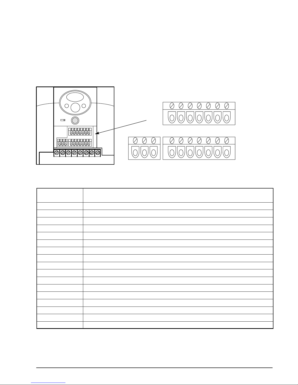
Figure 5‐1 Control Wiring Terminal Identification
Control I/O Terminal Strip
P4 P5 VR V1 CM
I
AM
30A 30B 30C MO EXTGP24 P1 P2 CM P3
Tightening Torque =
3.5 lb-in (0.4Nm)
See Table 4‐1 for
Tightening Torques
NPN
PNP
Table 5‐1 I/O Connection Description
Connector
Terminal
Signal Description
P1 Forward Run
P2 Reverse Run
P3 Output Inhibit
P4 Fault Reset
P5 Jog Operation
P24 Internal 24VDC power (powers P1-P5 inputs)
VR 12V power supply for speed reference potentiometer
V1 0-10VDC Analog Input Terminal
I
0-20mA Analog Input Terminal
CM Internal 24V common (return for P1-P5 and AM inputs)
AM 0-10VDC Analog Output Terminal
CM Common for Analog Output
MO Digital Output (Open Collector)
EXTG Digital Common for MO
30A Relay Output - A Contact
30B Relay Output - B Contact
30C Common - 30A, 30B Contacts
5-2 Control Wiring MN761
5.2 Control Input Connections
Determine if you will use NPN (factory setting) or PNP connections. NPN/PNP settings are shown in
Figure 5‐2. For NPN, CM (Common or ground) is used to switch the input signals. For PNP, P24
(+24VDC output) is used to switch the input signals.
Figure 5‐2 NPN/PNP Mode
Set the NPN/PNP switch for desired mode.
NPN Mode
PNP Mode
OR
See Table 4‐1 for Tightening
Torques
NPN
PNP
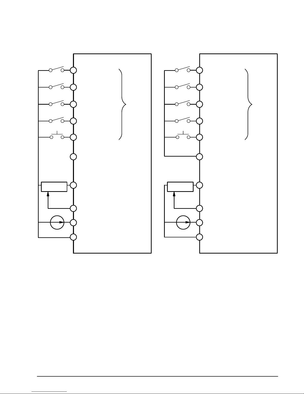
Input connections are shown in Figure 5‐3
1. For NPN Connections Connect the Digital Inputs to one pole of a switch and the other switch pole
to CM. An active low at P1 - P5 will activate the inputs.
For PNP Connections1 Connect the Digital Inputs to one pole of a switch and the other switch
pole to P24. An active High at P1 - P5 will activate the inputs.
2. The speed Command input can be wither a Voltage (0-10VDC) or a Current (0-20mA) input.
For Voltage input, either an external potentiometer or an external voltage reference can be used.
a. For an External reference voltage input, connect the 0-10VDC input to the VI terminal.
Connect the reference from the external source to the CM terminal.
b. For an external potentiometer, connect the pot as shown, one end to VR terminal, the wiper to
VI terminal and the other end to CM terminal.
For Current input, connect the 0-20mA source to the I terminal, the reference to CM terminal.
MN761 Control Wiring 5-3
Figure 5‐3 Input Connections
Forward Run
Speed signal input
(0-10VDC )
Speed signal input (0-20mA)
P1
P2
P3
P4
P5
P24
VR
VI
I
CM
Reverse Run
Output Inhibit
Jog Operation
Fault Reset
Internal 10VDC
Power for Potentiometer
PNP 24VDC Output
Common
Shown with NPN Digital Input Connections
VS1SM
Tightening Torque = 3.5 lb-in (0.4Nm)
Digital
Inputs
Forward Run
Speed signal input
(0-10VDC )
Speed signal input (0-20mA)
P1
P2
P3
P4
P5
P24
VR
VI
I
CM
Reverse Run
Output Inhibit
Jog Operation
Fault Reset
Internal 10VDC
Power for Potentiometer
PNP 24VDC Output
Common
Shown with PNP Digital Input Connections
VS1SM
Digital
Inputs
5-4 Control Wiring MN761
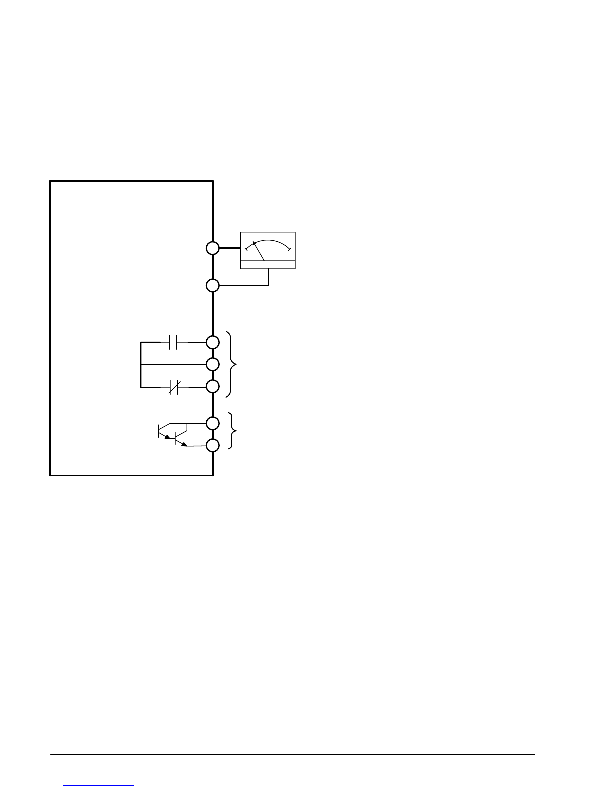
5.3 Control Output Connections
The Analog and Digital outputs are shown in Figure 5‐4.
1. Connect an external analog output device to AM terminal and it's reference to CM.
2. The normally Open and Closed relay outputs can be connected to an external device, terminal 30B
is the common terminal.
3. A multi-function open collector output can drive a digital load, connect to MO and EXTG.
Figure 5‐4 Output Connections
AM
CM
30A
30B
30C
MO
EXTG
VS1SM
Tightening Torque = 3.5 lb-in (0.4Nm)
Relay Output
Digital Output
Analog Output
(0-10VDC)
MN761 Using the Keypad 6-1
Chapter 6
Using the Keypad
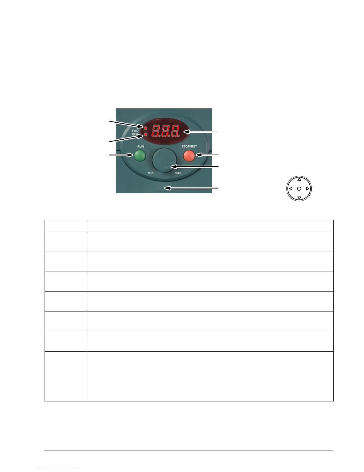
6.1 Keypad Overview
Operator controls are shown in Figure 6‐1 and described in Table 6‐1.
The 5 Way Button that is used for parameter setting is only accessible when the cover is removed.
Figure 6‐1 Operator Controls
Display
Stop/Reset Switch
Speed Adjustment
Potentiometer
Run Switch
FWD Run LED
REV Run LED
5 Way Button
(Must remove cover to access)
Table 6‐1 Key Descriptions
Item
Description
FWD FWD Run LED:
On during Forward Run.
REV REV Run LED:
On during Reverse Run.
DISPLAY 7 Segment LED Display:
Displays operation status and parameter information.
RUN Run Switch:
Press to issue a run command.
STOP/RST Stop / Reset Switch:
STOP: Stop the operation RST: Reset faults
POTENTIO-
METER
Speed Adjustment Potentiometer:
Adjusts the value of run frequency.
5 WAY
BUTTON
5 Way Button: (Not visible with cover on.)
Y Navigate parameter lists or increase parameter value.
B Navigate parameter lists or decrease parameter value.
" Navigate parameter groups or move cursor to the right to change the parameter value.
A Navigate parameter groups or move a cursor to the left to change the parameter value.
F Set the parameter value or save the changed parameter value (Enter).
6-2 Using the Keypad MN761
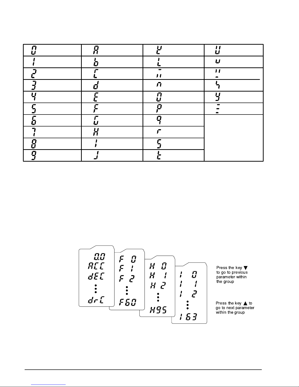
Figure 6‐2 Alpha-numeric LED Characters
1B L V
0A K U
2C M W
3D N X
4E O Y
5F P Z
7H R
8I S
9J T
6G Q
6.2 Parameter Groups
To access the parameter groups the cover must be removed to allow access to the 5 Way Button.
The 5 Way Button is used to navigate the parameters and examine or change values.
There are 4 parameter groups in VS1SM shown in Figure 6‐3.
Drive Group Basic start up parameters necessary to run the drive.
Function Group1 Basic function parameters to adjust output speed/voltage, minimum/maximum
speeds and braking.
Function Group2 Advanced function parameters.
I/O Group Parameters to configure the digital and analog I/O and to set preset speeds.
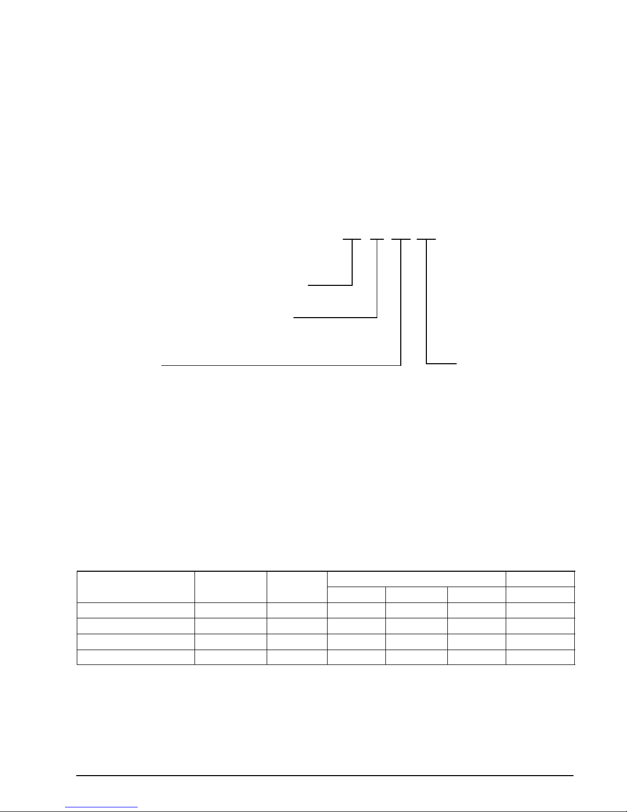
Figure 6‐3
I/O group
Fun ction
group 1
Drive group
Function
group 2
Press the " key to navigate to the next group. Press the A key to navigate to the previous group.
 Loading...