

Baldor VS1MXS51, VS1MXS55, VS1MXS52, VS1MXS53, VS1MXS57 Installation & Operating Manual

03/11 Installation & Operating Manual MN762S
VS1MXS
AC Extreme Duty Microdrive

Any trademarks used in this manual are the property of their respective owners.
Important:
Be sure to check www.baldor.com for the latest software, firmware and drivers for your
VS1MXS product. Also you can download the latest version of this manual in Adobe Acrobat
PDF format.

iMN762S
Chapter 1
Introduction
1.1 Getting Assistance from Baldor ............................................................ 1-1
1.2 Safety Notice .......................................................................... 1-1
1.3 Quick Start. . . . . . . . . . . . . . . . . . . . . . . . . . . . . . . . . . . . . . . . . . . . . . . . . . . . . . . . . . . . . . . . . . . . . . . . . . . . 1-3
Chapter 2
General Information and Rating
2.1 Identify the Drive by Model Number ......................................................... 2-1
2.2 Storage Guidelines ...................................................................... 2-1
2.3 VS1MXS Ratings, Model Numbers and Frame Sizes ............................................. 2-2
Chapter 3
Installing the Drive
3.1 Receiving & Inspection ................................................................... 3-1
3.2 General Requirements for the Installation Site ................................................. 3-1
3.2.1 Operating Conditions .............................................................. 3-1
3.2.2 Minimum Mounting Clearances ...................................................... 3-1
3.3 Mounting the Drive ..................................................................... 3-2
3.3.1 Protecting the Drive from Debris ..................................................... 3-2
3.3.2 Watts Loss Data .................................................................. 3-2
3.3.3 Elevation ....................................................................... 3-2
3.4 Cover Removal. . . . . . . . . . . . . . . . . . . . . . . . . . . . . . . . . . . . . . . . . . . . . . . . . . . . . . . . . . . . . . . . . . . . . . . . . 3-2
3.5 Conduit Size and Lock off ................................................................ 3-4
Chapter 4
Power Wiring
4.1 Overview of Power Connections ............................................................ 4-1
4.1.1 Safety Ground ................................................................... 4-1
4.1.2 Motor Ground ................................................................... 4-1
4.1.3 Shield Termination ................................................................ 4-1
4.1.4 RFI Filter Grounding ............................................................... 4-1
4.2 Power Disconnect ...................................................................... 4-2
4.3 Protective Devices ...................................................................... 4-2
4.4 Electrical Installation .................................................................... 4-2
4.4.1 Branch Circuit Protection .......................................................... 4-2
4.4.2 Single Phase Input Power Connections for 1 Phase Control ................................. 4-2
4.4.3 Three Phase Input Power Connections for 3 Phase Control .................................. 4-2
4.4.4 Optional Dynamic Brake Hardware Frame B Controls ...................................... 4-3
4.4.5 Motor Connections ................................................................ 4-3
4.4.6 Long Motor Leads ................................................................ 4-4
4.4.7 M-Contactor Connections .......................................................... 4-4
Chapter 5
Control Wiring
5.1 Control Wiring Overview .................................................................. 5-1
5.2 RJ11 Communication Connection .......................................................... 5-2
5.3 Analog and Digital Input Configurations ...................................................... 5-3
5.3.1 Terminal Strip Mode ............................................................... 5-3
5.3.2 Keypad Mode .................................................................... 5-6
5.3.3 PI Control Mode .................................................................. 5-8
5.3.4 User PI Control Mode .............................................................. 5-9
Chapter 6
Using the Keypad
6.1 Keypad Overview ....................................................................... 6-1
6.2 Using the REV/0/FWD Selector Switch ....................................................... 6-2
6.3 Changing Parameters ................................................................... 6-2
6.4 Reset Factory Default Settings ............................................................. 6-3
6.5 Advanced Keypad Operation Shortcuts ....................................................... 6-3
6.6 Terminal Control ........................................................................ 6-4
6.7 Keypad Control ........................................................................ 6-4
6.8 Motor Auto Tuning ...................................................................... 6-5
6.8.1 AutoTune after Factory Reset or from Factory Set Parameters ............................... 6-5
6.8.2 User Selected Auto Tune ........................................................... 6-5
Table of Contents

ii MN762S
6.9 Operating in Sensorless Vector Speed Control Mode ............................................ 6-5
6.10 Sensorless Vector Torque Control Mode ...................................................... 6-6
Chapter 7
Parameter Descriptions
7.1 Overview ............................................................................. 7-1
7.2 Basic Parameters - Parameter Group 1 ...................................................... 7-1
7.3 Extended Parameters .................................................................... 7-4
7.3.1 Parameter Group 2 – Extended Parameters ............................................. 7-4
7.3.2 Parameter Group 3 – PID Control ..................................................... 7-10
7.3.3 Parameter Group 4 – How Performance Motor Control ..................................... 7-12
7.3.4 Parameter Group 0 – Monitoring Parameters (Read Only) ................................... 7-14
7.4 Advanced Parameters ................................................................... 7-16
7.4.1 Advanced Parameters - Parameter Group 5 ............................................. 7-16
7.4.2 Application Specific Parameters - Parameter Group 6 ..................................... 7-19
7.4.3 Additional Parameter Group 0 – Monitoring Parameters .................................... 7-22
Chapter 8
Customizing for Your Application
8.1 Simple Parameter Adjustments ............................................................ 8-1
Chapter 9
Troubleshooting
9.1 Fault Codes ........................................................................... 9-1
9.2 Periodic Inspection. . . . . . . . . . . . . . . . . . . . . . . . . . . . . . . . . . . . . . . . . . . . . . . . . . . . . . . . . . . . . . . . . . . . . . 9-1
Appendix A
Technical Specifications .................................................................... A-1
Appendix B
Parameter Tables .......................................................................... B-1
Appendix C
CE Guidelines
C.1 CE Declaration of Conformity .............................................................. C-1
C.2 EMC - Conformity and CE - Marking ........................................................ C-1
C.3 EMC Installation Options ................................................................. C-2
C.4 Grounding for Wall Mounting (Class A) also see Chapters 4 and 5 .................................. C-2
C.5 Grounding for Enclosure Mounting (Class B) also see Chapters 4 and 5 .............................. C-2
C.6 Using CE approved components will not guarantee a CE compliant system ........................... C-2
C.7 EMC Wiring Technique ................................................................... C-3
C.8 EMC Installation Instructions .............................................................. C-4
Appendix D
Options & Kits
D.1 Accessories ........................................................................... D-1
Appendix E
RS485/MODBUS Protocol
E.1 Introduction ........................................................................... E-1
E.2 Installation ............................................................................ E-1
E.3 Operation ............................................................................. E-1
E.4 Performance Specifications ............................................................... E-2
E.5 Hardware Specifications ................................................................. E-2
E.6 Communication Specifications ............................................................. E-2
E.7 Communications Protocol (MODBUS-RTU) .................................................... E-2
E.8 Modbus Register Map ................................................................... E-3

Introduction 1-1MN762S
Chapter 1
Introduction
This manual is intended for qualified electrical personnel familiar with installing, programming, and
maintaining AC Drives. This manual contains information on:
•Installing and wiring the VS1MXS drive
•Programming the drive
•Troubleshooting the drive
1.1 Getting Assistance from Baldor
For technical assistance, contact your Baldor District Office. Before calling, please review the
troubleshooting section of this manual. You will be asked for the drive model number or catalog
number that is located on the Nameplate along with the drive serial number.
1.2 Safety Notice
This equipment contains voltages that may be as high as 1000 volts! Electrical shock can cause
serious or fatal injury. Only qualified personnel should attempt the start-up procedure or troubleshoot
this equipment.
This equipment may be connected to other machines that have rotating parts or parts that are driven
by this equipment. Improper use can cause serious or fatal injury. Only qualified personnel should
attempt the start-up procedure or troubleshoot this equipment.
CLASSIFICATIONS OF CAUTIONARY STATEMENTS
WARNING: Indicates a potentially hazardous situation which, if not avoided, could result in injury or
death.
CAUTION: Indicates a potentially hazardous situation which, if not avoided, could result in damage
to property.
PRECAUTIONS
WARNING: Do not touch any circuit board, power device or electrical connection before you first
ensure that power has been disconnected and there is no high voltage present from this
equipment or other equipment to which it is connected. Electrical shock can cause serious
or fatal injury. Only qualified personnel should attempt the start-up procedure or
troubleshoot this equipment.
WARNING: Be sure that you are completely familiar with the safe operation of this equipment. This
equipment may be connected to other machines that have rotating parts or parts that are
controlled by this equipment. Improper use can cause serious or fatal injury. Only qualified
personnel should attempt the start-up procedure or troubleshoot this equipment.
WARNING: Do not use motor overload relays with an automatic reset feature. These are dangerous
since the process may injure someone if a sudden or unexpected automatic restart occurs.
If manual reset relays are not available, disable the automatic restart feature using
external control wiring.
WARNING: This unit has an automatic restart feature that will start the motor whenever input power is
applied and a RUN (FWD or REV) command is issued. If an automatic restart of the motor
could cause injury to personnel, the automatic restart feature should be disabled.
WARNING: Be sure the system is properly grounded before applying power. Do not apply AC power
before you ensure that all grounding instructions have been followed. Electrical shock can
cause serious or fatal injury.

1-2 Introduction MN762S
WARNING: Do not remove cover for at least five (5) minutes after AC power is disconnected to allow
capacitors to discharge. Dangerous voltages are present inside the equipment. Electrical
shock can cause serious or fatal injury.
WARNING: Improper operation of control may cause violent motion of the motor shaft and driven
equipment. Be certain that unexpected motor shaft movement will not cause injury to
personnel or damage to equipment. Certain failure modes of the control can produce peak
torque of several times the rated motor torque.
WARNING: Motor circuit may have high voltage present whenever AC power is applied, even when
motor is not rotating. Electrical shock can cause serious or fatal injury.
WARNING: Dynamic brake resistors may generate enough heat to ignite combustible materials. Keep
all combustible materials and flammable vapors away from brake resistors.
WARNING: The motor shaft will rotate during the autotune procedure. Be certain that unexpected
motor shaft movement will not cause injury to personnel or damage to equipment.
WARNING: MEDICAL DEVICE/PACEMAKER DANGER - Magnetic and electromagnetic fields in the
vicinity of current carrying conductors and industrial motors can result in a serious health
hazard to persons with cardiac pacemakers, internal cardiac defibrillators,
neurostimulators, metal implants, cochlear implants, hearing aids, and other medical
devices. To avoid risk, stay away from the area surrounding a motor and its current
carrying conductors.
CAUTION: Disconnect motor leads (U, V and W) from control before you perform a dielectric withstand
(insulation) test on the motor. Failure to disconnect motor from the control will result
in extensive damage to the control. The control is tested at the factory for high voltage/
leakage resistance as part of the Underwriters Laboratory requirements.
CAUTION: Suitable for use on a circuit capable of delivering not more than the RMS symmetrical
short circuit amperes listed here at rated voltage.
Horsepower RMS Symmetrical Amperes
1 - 7-1/2 5,000
CAUTION: Do not connect AC power to the Motor terminals U, V and W. Connecting AC power to these
terminals may result in damage to the control.
CAUTION: Baldor does not recommend using “Grounded Leg Delta” transformer supplies that may
create ground loops. Instead, we recommend using a four wire Wye.
CAUTION: If the DB hardware mounting is any position other than vertical, the DB hardware must be
derated by 35% of its rated capacity.
CAUTION: Only Baldor cables should be used to connect the keypad and control. These are special
twisted pair cables to protect the control and the keypad. Damage associated with other
cable types are not covered by the Baldor warranty.
CAUTION: If an M-Contactor is installed, the control must be disabled for at least 200msec before the
M-Contactor is opened. If the M-Contactor is opened while the control is supplying voltage
and current to the motor, the control may be damaged. Before the control is enabled, the
M-Contactor must be closed for at least 200msec.
CAUTION: Use of power correction capacitors on the output of the drive can result in erratic operation
of the motor, nuisance tripping, and/or permanent damage to the drive. Remove power
correction capacitors before proceeding. Failure to observe this precaution could result in
damage to, or destruction of, the equipment.
CAUTION: Integral solid state short circuit protection does not provide branch circuit protection.
Branch circuit protection must be provided in accordance with the National Electric Code
and any additional local codes.
Introduction 1-3MN762S
1.3 Quick Start
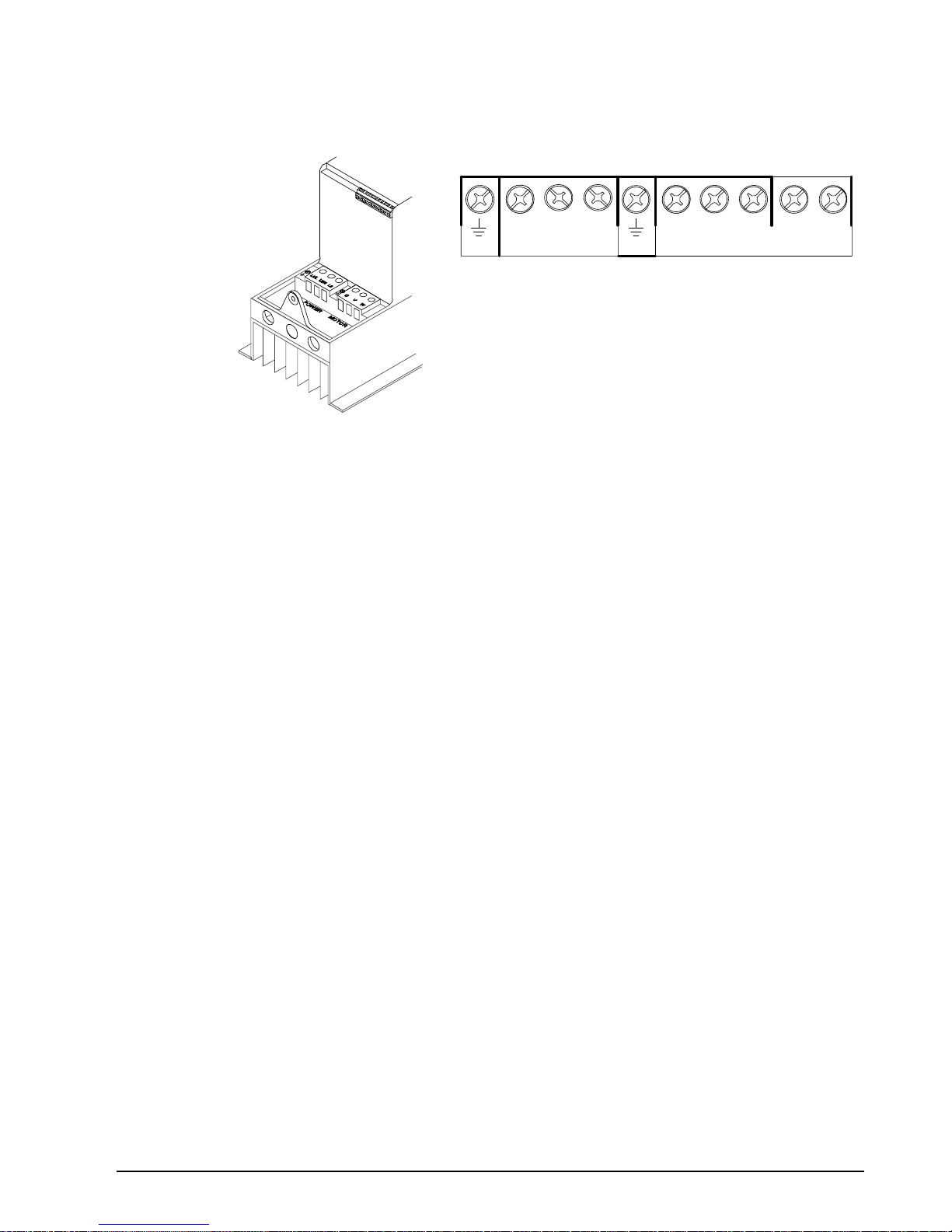
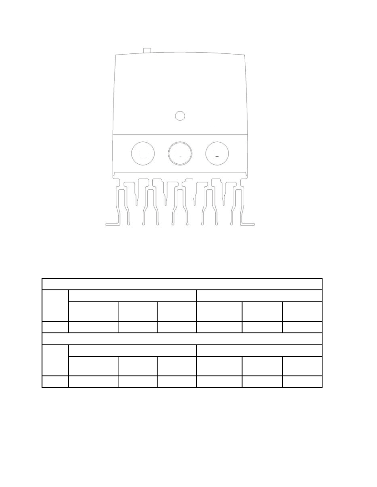
Figure 1-1 Power & Motor Terminal Locations
L1/L L 2/N L3
Frame B
(VS1MXS51 shown
as an example)
See Recommended Tightening
Torques in Table 4-1.
U V W + BR
Frame B
Power Up Procedure (Refer to Chapter 3, 4 and 5 for additional details.
1. Remove all power from the control.
2. Couple the motor to its load.
3. Verify freedom of motion of motor shaft.
4. Verify the motor coupling is tight without backlash.
5. Connect input control wires and output control wires, See Figure 1-2.
6. (Switched Version) Place Direction Command switches in OFF Position.
(Keypad version) Connect a control switch between terminals 1 and 2 ensuring that the contact is
open (drive disabled)
7. Connect Power & Motor wires to the control, See Figure 1-1.
8. Turn power on. Be sure there are no faults. For switched version, place the Power On/Off switch in
ON position.
9. Set the following parameters for the values displayed on the motor nameplate:
P1-01 Motor Rated Voltage
P1-02 Motor Rated Current
P1-03 Motor Rated Frequency
P1-04 Motor Rated Speed
10. (Switched Version) set P1-07 Start/Stop Source to 0.
(Keypad version) set P1-07 Start/Stop Source to 1 or 2.
11. Verify the holding brakes if any, are properly adjusted to fully release and set to the desired torque.
12. (Switched version) Run the drive from the front panel controls.
(Keypad version) Enable the drive by closing the switch between control terminals 1 & 2. Run the
drive from the keypad.
13. Select and program additional parameters to suit your application, see Chapter 7.
The control is now ready for use. If a different operating mode is desired, refer to Chapter 7 Parameter
Descriptions and Chapter 8 Customizing for your Application.
1-4 Introduction MN762S
Figure 1-2 Input Connections
Red
Blu
Yel
Grn
Wht
Blk
Front
Panel
Potentiometer
Front
Panel
FWD-REV
Switch
1
2
3
4
5
VS1MXS
Tightening Torque = 3.5 lb-in (0.4Nm)
+24VDC Reference
Stop-Run (Digital In1)
6
7
Analog-Preset (Digital In2)
Preset 1-Preset 2 (Digital In3 / Analog In2)
+10VDC POT Reference
Analog In1
Analog Common
Relay Output
10
11
8
9
C ommon
Analog / Digital Output
Analog Output
(0-10V DC )
* Optional Hardware not provided.
** Only provided in Switched version.
*
Control Wiring
Terminals
Only on
Switched versions
**
**
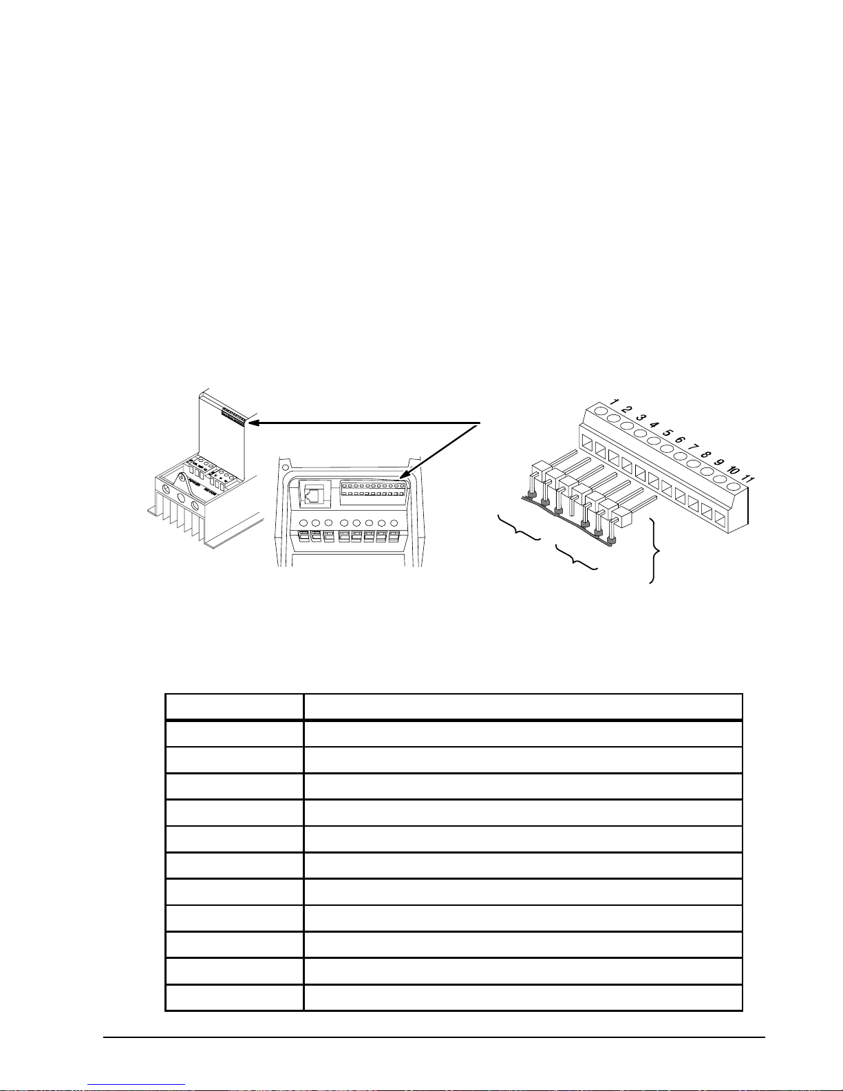
Table 1-1 Control Terminal Descriptions
Terminal Signal Description
1 +24VDC (@ 100 mA)
2 Digital In1
3 Digital In2
4 Digital In3 / Analog In2
5 +10VDC (@ 10 mA) Reference for Potentiometer (1kohm minimum)
6 Analog In1 / Digital In4
7 Common (terminals 7 & 9 are connected)
8 Analog Output (0-10VDC @ 10mA) / Digital Output (0-24VDC)
9 Common (terminals 7 & 9 are connected)
10 Relay Common
11 Relay N.O. Contact (rated 250VAC@6A; 30VDC@5A)

General Information and Ratings 2-1MN762S
Chapter 2
General Information and Ratings
The VS1MXS is an adjustable frequency PWM drive operating in V/Hz (volts per hertz) mode. This
chapter contains information about the VS1MXS drive, including how to identify the drive.
2.1 Identify the Drive by Model Number
Each drive can be identified by its model number, as shown in Figure 2-1. The model number is one
the shipping label and the drive nameplate. The model number includes the drive and any options.
Figure 2-1 Drive Identification
VS1MXS 5 5 - 2 TD
VS1 Family
MXS Microdrive
Voltage Code
5 = 500 - 600Vac 1PH
Power Rating
Hp Rated kW Rated
1 = 1 0P8 = 0.75
2 = 2 1P5 = 1.5
3 = 3 2P2 = 2.2
5 = 5 4 = 4
7 = 7.5 5P5 = 5.5
Options
T = Internal Brake Transistor
D = Disconnect Switch
2 = NEMA 12 / IP55
Enclosure
2.2 Storage Guidelines
Follow these recommendations to prolong drive life and performance if storing the drive:
1. Storage surrounding temperature is -40°C to 60°C.
2. Storage Humidity range 10% to 95% RH non-condensing.
3. Do not expose to corrosive atmosphere.

2-2 General Information and Ratings MN762S
2.3 VS1MXS Ratings, Model Numbers and Frame Sizes
Table 2-1 Drive Ratings
HP Model Number HP kW
Current (Amps)
Frame Watts Loss
Input Output
500-600V +/-10% 3-Phase Input
VS1MXS51 1 0.75 2.2 1.7 B 50
VS1MXS52 2 1.5 4.1 3.1 B 90
VS1MXS53 3 2.2 5.4 4.1 B 90
VS1MXS55 5 4 7.6 6.1 B 130
VS1MXS57 7.5 5.5 11.7 9 B 240

Installing the Drive 3-1MN762S
Chapter 3
Installing the Drive
This chapter provides information that must be considered when planning a VS1MXS drive installation
and provides drive mounting information and installation site requirements.
3.1 Receiving & Inspection
When you receive your control, there are several things you should do immediately.
1. Observe the condition of the shipping container and report any damage immediately to the
commercial carrier that delivered your control.
2. Remove the control from the shipping container and remove all packing materials from the
control. The container and packing materials may be retained for future shipment.
3. Verify that the part number of the control you received is the same as the part number listed on
your purchase order.
4. Inspect the control for external physical damage that may have been sustained during shipment
and report any damage immediately to the commercial carrier that delivered your control.
5. If the control is to be stored for several weeks before use, make sure that it is stored in a location
that conforms to published storage humidity and temperature specifications stated in this manual.
3.2 General Requirements for the Installation Site
It is important to ensure that the drive’s environment and operating conditions are satisfactory. The
area behind the drive must be kept clear of all control and power wiring. Power connections may
create electromagnetic fields that may interfere with control wiring or components when run in close
proximity to the drive. Read the recommendations in the following sections before continuing with the
drive installation.
3.2.1 Operating Conditions
•Operating surrounding temperature must be within 32°F (0°C) to 104°F (40°C).
If surrounding temperature exceeds 40°C, de-rate the output by 5% per °C above 40°C up to 55°C
maximum surrounding temperature.
•Protect the cooling fan by avoiding dust or metallic particles.
•Do not expose the drive to a corrosive atmosphere.
•Protect the drive from moisture and direct sunlight.
•Verify that the drive location will meet the environmental conditions specified in Table 3-1.
3.2.2 Minimum Mounting Clearances
Be sure to provide proper top and bottom clearance 5.9 inches (150mm) for cooling.
Side to side clearance is minimal and controls can be almost touching.
Table 3-1 Surrounding Temperatures and Mounting Clearances
Surrounding Temperature
Enclosure Rating
Minimum Mounting Clearances
(Vertical)
Minimum Maximum
32°F (0°C) 104°F (40°) NEMA 12 / IP55 5.9 in (150mm)
3-2 Installing the Drive MN762S
3.3 Mounting the Drive
Mount the drive upright on a flat, vertical, level surface using Table 3-2 NEMA 12 / IP55 Dimensions
for mounting locations.
3.3.1 Protecting the Drive from Debris
The drive is designed to operate in NEMA 12 (IP55) Type installations.
3.3.2 Watts Loss Data
Refer to Table 2-1 for watts loss data.
3.3.3 Elevation
Maximum elevation is 3300 ft (1000m) above sea level without de-rating. De-rate output power by
1% per 330 ft (100m) about 3300 ft to 6600 ft (2000m) maximum elevation.
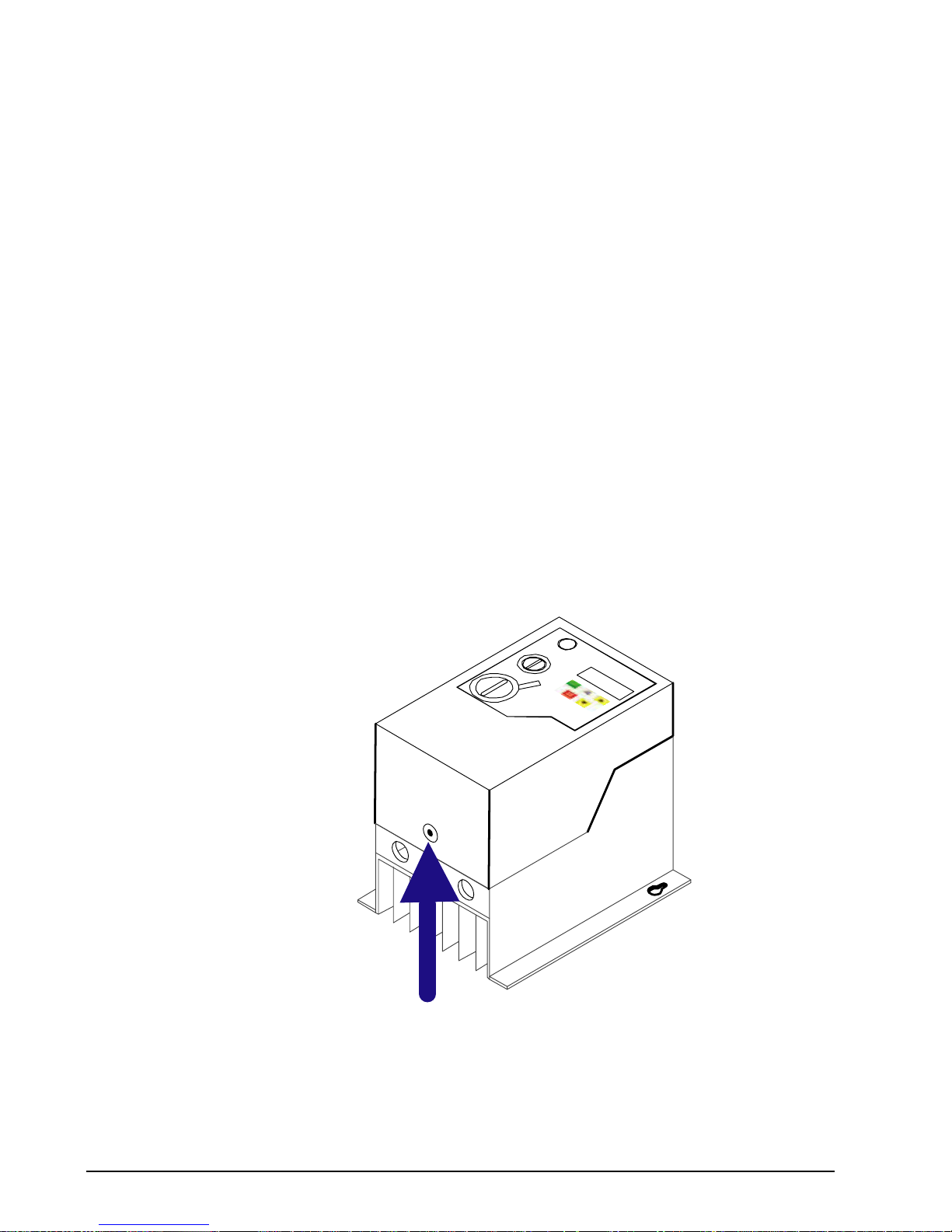
3.4 Cover Removal
To connect power and signal wires, the cover must be removed as shown in Figure 3-1.
Figure 3-1 Cover Removal
Press in (cover release)
then lift cover to remove.
Installing the Drive 3-3MN762S
Figure 3-2 NEMA 12 / IP55 Mounting Hole Locations
A1
A
B 1
B
STOP
RESET
START
PROG
ENT
Table 3-2 NEMA 12 / IP55 Dimensions
Frame
A A1 A2 B B1
I Φ J Φ
C
(Depth)
Weight
in
(mm)
in
(mm)
in
(mm)
in
(mm)
in
(mm)
in
(mm)
in
(mm)
in
(mm)
lb
(kg)
B
12.20
(310)
12.20
(310)
1.30
(33)
6.46
(164)
6.02
(153)
0.17
(4.2)
0.33
(8.4)
7.09
(180)
9.92
(4.5)
Control Terminal Torque Settings of 4.5 lb-in (0.5 Nm)
Power Terminal Torque Settings of 9 lb-in (1 Nm)
3-4 Installing the Drive MN762S
3.5 Conduit Size and Lock off
Figure 3-3 Opening Identification
B
A
C
Table 3-3 Opening Dimensions
Cable Gland recommended Hole Sizes and Types:
Frame
Size
Opening A and C Knock Out B
Diameter
UL
Gland Size
Metric
Gland Size
Diameter
UL Gland
Size
Metric
Gland Size
B 1.11 (28.2mm) PG21 M25 .866 (22mm) PG13.5 M20
Flexible Conduit Hole Sizes:
Frame
Size
Opening A and C Knock Out B
Diameter
UL
Gland Size
Metric
Gland Size
Diameter
UL Gland
Size
Metric
Gland Size
B 1.11 (28.2mm) 1 in 35mm .866 (22mm) 3/4 in 27
Note: UL rated ingress protection (“Type”) is only met when cables are installed using a UL recognized
bushing or fitting for a flexible-conduit system which meets the required level of protection
(“Type”). Not intended for rigid conduit system.
Power Wiring 4-1MN762S
Chapter 4
Power Wiring
4.1 Overview of Power Connections
The recommended grounding method is shown in Figure 4-1.
4.1.1 Safety Ground - (G)
This is the safety ground for the drive that is required by code. One of these points must be connected
to adjacent building steel (girder, joist), a floor ground rod, or bus bar. Grounding points must comply
with national and local industrial safety regulations and/or electrical codes.
Figure 4-1 Recommended System Grounding
L1
AC Main
Supply
Safety
Ground
Driven Earth
Ground Rod
(Plant Ground)
Four Wire
Wye
L1
L2
L3
Earth
L2 L3 U V W
Optional
Line
Reactor
Optional
Load
Reactor
Route all 4 wires L1, L2, L3 and Earth (Ground)
together in conduit or cable.
Route all 4 wires U, V, W and Motor Ground together
in conduit or cable.
Connect all wires (including motor ground)
inside the motor terminal box.
Ground per NEC and
Local codes.
Note: Wiring shown for clarity of grounding
Method only. Not representative of
actual terminal block location.
Note: A load reactor is recommended
and must be purchased separately..
Note: A line reactor is recommended
and must be purchased separately..
Drive
See recommended tightening torques in Table 4-1.
Use UL Listed Fork terminals for ground connections.
4.1.2 Motor Ground
The motor ground must be connected to one of the ground terminals on the drive. Use UL Listed Fork
terminals for ground connections.
4.1.3 Shield Termination
Either of the safety ground terminals located on the power terminal block provides a grounding point
for the motor cable shield. The motor cable shield connected to one of these terminals (drive end)
should also be connected to the motor frame (motor end). Use a shield terminating or EMI clamp to
connect the shield to the safety ground terminal. When shielded cable is used for control and signal
wiring, the shield should be grounded at the drive end only, never at both ends.
4.1.4 RFI Filter Grounding
Using single-phase drives with integral filter, or an external filter with any drive rating, may result in
relatively high ground leakage currents. Therefore, the filter must only be used in installations with
grounded AC supply systems and be permanently installed and solidly grounded (bonded) to the
building power distribution ground.

4-2 Power Wiring MN762S
Ensure that the incoming supply neutral is solidly connected (bonded) to the same building power
distribution ground. Grounding must not rely on flexible cables and should not include any form of
plug or socket that would permit inadvertent disconnection. Some local codes may require redundant
ground connections. The integrity of all connections should be checked periodically.
4.2 Power Disconnect
A power disconnect should be installed between the input power service and the drive for a fail safe
method to disconnect power. The drive will remain in a powered-up condition until all input power is
removed from the drive and the internal bus voltage is depleted.
4.3 Protective Devices
Recommended fuse sizes are based on the following:
115% of maximum continuous current for time delay.
150% of maximum continuous current for Fast or Very Fast action.
Note: These recommendations do not consider harmonic currents or surrounding temperatures
greater than 45°C. Be sure a suitable input power protection device is installed. Use the
recommended fuses and wire sizes shown in Table 4-1 is based on the use of copper
conductor wire rated at 75°C. The table is specified for NEMA B motors.
Fast Action Fuses: 240VAC, Buss® KTN; 460VAC, Buss® KTS
Very Fast Action: 240VAC, Buss® JJN; 460VAC, Buss® JJS
Semiconductor: 240VAC, Ferraz Shawmut A50QS
Buss® is a trademark of Cooper Industries, Inc.
4.4 Electrical Installation
All interconnection wires between the drive, AC power source, motor, host control and any operator
interface stations should be in metal conduits or shielded cable must be used. Use listed Fork
connectors that are of appropriate size for wire gauge being used. Connectors are to be installed
using crimp tool specified by the manufacturer of the connector. Only Class 1 wiring should be used.
4.4.1 Branch Circuit Protection
These devices require branch circuit protection. Branch circuit protection shall be provided. The size of
the Branch Circuit Protection Fuse shall be as shown in the ratings table or equivalent.
4.4.2 Single Phase Input Power Connections for 1 Phase Control
All cables must be shielded and the shields must be grounded at the enclosure cable entrance.
1. Connect the single phase input power wires to an appropriate interrupter and protection.
2. Connect the single phase AC input power leads to terminals L1/L and L2/N of the control (see
Figure 4-2 for location).
3. Connect the power ground wire to the ground terminal.
4.4.3 Three Phase Input Power Connections for 3 Phase Control
All cables must be shielded and the shields must be grounded at the enclosure cable entrance.
1. Remove cover. Cover removal is described in Chapter 3 of this manual.
2. Connect the three phase input power wires to an appropriate interrupter and protection.
3. Connect the three phase AC input power leads to terminals L1/L. L2/N and L3 of the control (see
Figure 4-2 for location).
4. Connect the power ground wire to the ground terminal (see Figure 4-2).
Power Wiring 4-3MN762S
Figure 4-2 Wiring Locations
L1/L L2/N L3
Frame B
(VS1MXS51 shown
as an example)
Frame B
U V W + BR
See Recommended Tightening
Torques in Table 4-1.
4.4.4 Optional Dynamic Brake Hardware Frame B Controls
If optional DB resistor is to be used, connect it to the + and BR terminals, (see Figure 4-2). Dynamic
Brake (DB) Hardware must be installed on a flat, non-flammable, vertical surface for effective cooling
and operation. The DB Resistors get extremely hot during normal operation and must be mounted
away from flammable surfaces and unsafe atmosphere.
Table 4-1 Fuse & Wire size / Terminal Torque Specifications
Hp kW
Nominal
Input
Current
Fuse
or
MCB
Supply
Cable Size
Nominal
Output
Current
Motor Cable
Size
Max Motor
Cable Length
Min
Brake
Resistor
Value
amps amps AWG mm2 Amps AWG mm2 Feet Meters Ohms
500-600V +/-10% 3-Phase Input
1 0.75 2.2 3 15 1 1.7 15 1 164 50 47
2 1.5 4.1 6 15 1 3.1 15 1 328 100 47
3 2.2 5.4 6 15 1 4.1 15 1 328 100 47
5 4 7.6 10 15 1.5 6.1 15 1.5 328 100 47
7.5 5.5 11.7 16 14 2.5 9 14 2.5 328 100 47
Control Terminal Torque Settings of 4.5 lb-in (0.5 Nm)
Power Terminal Torque Settings of 9 lb-in (1 Nm)
For UL compliance Motor Cable to be Copper 75°C and Fuse current rating defined by ratings marked
( )*.
Wire size is based on 40°C surrounding and fuses are based on 45°C surrounding, max continuous
output and no harmonic current.
4.4.5 Motor Connections
All cables must be shielded and the shields must be grounded at the enclosure cable entrance.
1. Remove covers. Cover removal is described in Chapter 3 of this manual.
2. Connect the Motor leads to terminals U, V and W (See Figure 4-2 for location).
3. Connect the motor ground wire to the ground terminal (See Figure 4-2).
4-4 Power Wiring MN762S
4.4.6 Long Motor Leads
The wire leads that connect the motor to the control are critical in terms of sizing, shielding and the
cable characteristics. Short cable runs are usually trouble free but fault-monitoring circuitry can
produce numerous faults when long cables are used. Refer to Table 4-1 for maximum cable lengths.
Baldor recommends adding an optional load reactor to the output of the control. The load reactor and/
or common mode choke should be placed in close physical proximity to the control.
Unexpected faults may occur due to excessive charging current required for motor cable capacitance.
If you use long motor leads and experience unexpected trips due to current overload conditions and
are not sure how to correctly size and connect the optional load reactors, please contact your Baldor
District representative. Baldor is always glad to assist.
4.4.7 M-Contactor Connections
If required by local codes or for safety reasons, an M-Contactor (motor circuit contactor) may be
installed. However, incorrect installation or failure of the M-contactor or wiring may damage the
control. If an M-Contactor is installed, the control must be disabled for at least 200msec before the
M-Contactor is opened or the control may be damaged. M-Contactor connections are shown in Figure
4-3.
CAUTION: If an M-Contactor is installed, the control must be disabled for at least 200msec before the
M-Contactor is opened. If the M-Contactor is opened while the control is supplying voltage and
current to the motor, the control may be damaged. Before the control is enabled, the M-Contactor
must be closed for at least 200msec.
Figure 4-3 Motor Connections and Optional Connections
*
Optional components not provided with control.
Baldor
Control
*
AC Motor
Note 1
*Optional
Load
Reactor
Note 1
A1 B1 C1
A2 B2 C2
U V W
U
V W
G
Note 3
* Optional
RC Device
Electrocube
RG1781-3
* M Enable
* M-Contactor
To Power Source
(Rated Coil Voltage)
M=Contacts of optional M-Contactor
GND
*Optional M Contactor Connections
Note 2
See Recommended Tightening
Torques in Table 4-1.
M
M
Notes:
1. Metal conduit should be used. Connect conduits
so the use of Load Reactor or RC Device does not
interrupt EMI/RFI shielding.
2. See Line/Load Reactors described previously in
this section.
3. Use same gauge wire for ground as for U, V and W.
Control Wiring 5-1MN762S
Chapter 5
Control Wiring
5.1 Control Board Connections
Analog and Digital input and output connections are made at the Control Wiring Terminals shown in
Figure 5-1.
Control wire connections can be made using shielded twisted pair #18 AWG (0.8mm2) wire minimum.
The cable must also have an overall shield and not exceed 100 feet (30m) in length. Control wire
cables must be separated from power wiring. Separate parallel runs of control cables and power
cables by at least 3”. Cross power wires at right angles only. Insulate or tape ungrounded end of
shields to prevent contact with other conductors or ground.
The Control Wiring Terminals are prewired to allow front panel Potentiometer and FWD-Off-Rev switch
operation. Simply remove these terminal connections (pins 1 to 7) and connect external devices as
desired. These terminals are described in Table 5-1.
Figure 5-1 Control Terminals
Red
Blu
Yel
Grn
Wht
Blk
Front
Panel
Potentiometer
Front
Panel
FWD-REV
Switch
Control Wiring
Terminals
Only on
Switched
version
Table 5-1 Control Terminal Descriptions
Terminal Signal Description
1 +24VDC (@ 100 mA)
2 Digital In1
3 Digital In2
4 Digital In3 / Analog In2
5 +10VDC (@ 10 mA) Reference for Potentiometer (1kohm minimum)
6 Analog In1 / Digital In4
7 Common (terminals 7 & 9 are connected)
8 Analog Output (0-10VDC @ 10mA) / Digital Output (0-24VDC)
9 Common (terminals 7 & 9 are connected)
10 Relay Common
11 Relay N.O. Contact (rated 250VAC@5A; 30VDC@5A)
5-2 Control Wiring MN762S
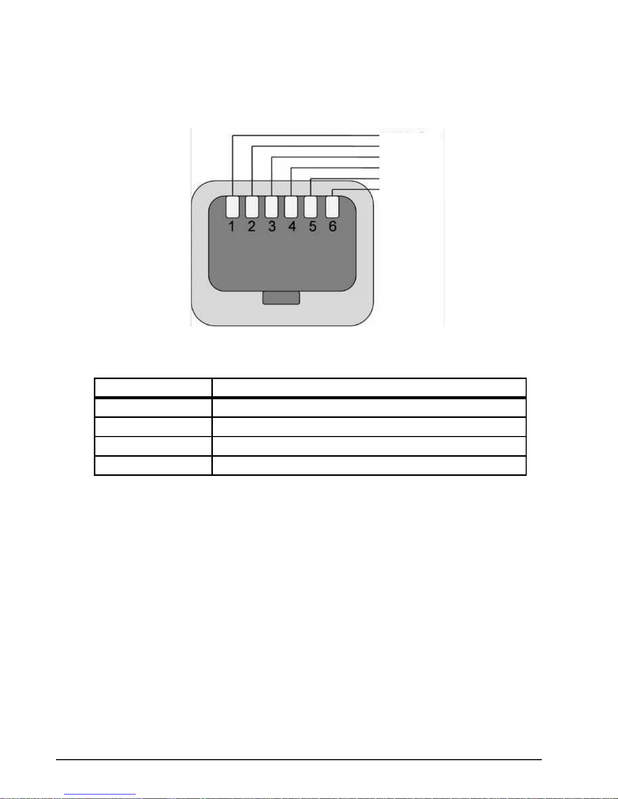
5.2 RJ11 Communication Connection
The RJ11 Data Port can be used as a RS485 Serial interface using Modbus RTU protocol.
Serial Modbus networks use the RS485 PIN connection; see Appendix E for the communication
protocols.
Figure 5-2 RJ11 Data Connection
RS485 Modbus +
0 Volts
+24 Volts
Optibus Optibus +
RS485 Modbus -
Table 5-2
Protocol Modbus RTU
Error check CRC
Baud rate 9600bps, 19200bps, 38400bps, 57600bps, 115200bps (default)
Data format 1 start bit, 8 data bits, 1 stop bits, no parity
Physical signal RS485 (2-wire)

Control Wiring 5-3MN762S
5.3 Analog and Digital Input Configurations
Parameters P1-07 and P1-08 can be set to allow various operating modes. Following are settings for
these parameters.
5.3.1 Terminal Strip Mode (P1-07 = 0)
Table 5-3 Parameter P1-08 Control of Digital Inputs when P1-07=0
P1-08
Digital In 1
(Term 2)
Digital In 2
(Term 3)
Digital In 3
(Term 4)
Analog Input
(Term 6)
0
Open: Stop
Open: Bipolar analog
speed reference
Open: Preset Speed 1
Bipolar analog input
Closed: Run
Closed: Preset speed
reference
Closed: Preset Speed 2
1
Open: Stop Open: Preset Speed 1 Open: Preset Speed 1/2
Open: Preset Speed
1/2/3
Closed: Run Closed: Preset Speed 2 Closed: Preset Speed 3
Closed: Preset
Speed 4
2
Open: Stop
Closed: Run
Digital Input 2 (Term 3)
Digital Input 3
(Term 4)
Bipolar analog
input (Term 6)
Speed Set point
Open Open Open Preset Speed 1
Closed Open Open Preset Speed 2
Open Closed Open Preset Speed 3
Closed Closed Open Preset Speed 4
Open Open Closed Preset Speed 5
Closed Open Closed Preset Speed 6
Open Closed Closed Preset Speed 7
Closed Closed Closed Preset Speed 8
3
Open: Stop Open: Forward Open: Bipolar analog ref
Bipolar analog input
Closed: Run Closed: Reverse Closed: Preset Speed 1
4
Open: Stop Open: Forward
Analog input 2
(Speed Reference)
Bipolar analog input
(Torque reference)
Closed: Run Closed: Reverse
5
Open: Stop
Closed: Run
Open: Forward
Closed: Reverse
Digital Input 3
(Term 4)
Bipolar analog
input (Term 6)
Speed Set point
Open Open Preset Speed 1
Closed Open Preset Speed 2
Open Closed Preset Speed 3
Closed Closed Preset Speed 4
6
Open: Stop
Closed: Run
Open: Forward
Closed: Reverse
External trip input:
Bipolar analog input Open: Trip
Closed: No Trip

5-4 Control Wiring MN762S
P1-08
Digital In 1
(Term 2)
Digital In 2
(Term 3)
Digital In 3
(Term 4)
Analog Input
(Term 6)
7
Open: Stop Open: Stop Open: Bipolar analog speed ref
Bipolar analog input
Closed: Fwd
Run
Closed: Rev Run Closed: Preset Speed 1
8
Open: Stop Open: Stop Open: Preset Speed 1
Bipolar analog input
Closed: Fwd
Run
Closed: Rev Run Closed: Bipolar analog speed ref
9
Open: Stop
Closed: Run
Fwd
Open: Stop
Closed: Reverse Run
Digital Input 3
(Term 4)
Bipolar analog
input (Term 6)
Preset Speed
Open Open Preset Speed 1
Closed Open Preset Speed 2
Open Closed Preset Speed 3
Closed Closed Preset Speed 4
10
Open: Stop Open: Stop Open: Trip
Bipolar analog input
Closed:
Forward Run
Closed: Reverse Run Closed: No Trip
11
Open: Stop
Open: Bipolar analog
speed ref
Open: Trip
Bipolar analog input
Closed: Run Closed: Preset Speed 1 Closed: No Trip
12
Open: Stop Open: Preset Speed 1 Open: Trip
Bipolar analog input
Closed: Run
Closed: Bipolar analog
speed ref
Closed: No Trip
13
Normally
Open (NO)
Normally Closed (NC) Open: Bipolar analog speed ref
Bipolar analog input
Momentarily
Close to Run
Momentarily Open to
Stop
Closed: Preset Speed 1
14
Normally
Open (NO)
Normally Closed (NC) Normally Open (NO)
Bipolar analog input
Momentarily
Close to Run
Fwd
Momentarily Open to
Stop
Momentarily Close to Run Rev
15
Open: Stop Open: Forward Open: Decel Ramp 1 (P1-11)
Bipolar analog input
Closed: Run Closed: Reverse Closed: Decel Ramp 2 (P2-25)
16
Open: Stop Open: Forward Open: Decel Ramp 1 (P1-11) Open: Preset Speed 1
Closed: Run Closed: Reverse Closed: Decel Ramp 2 (P2-25)
Closed: Preset
Speed 2
Table 5-3 Parameter P1-08 Control of Digital Inputs when P1-07=0 Continued

Control Wiring 5-5MN762S
P1-08
Digital In 1
(Term 2)
Digital In 2
(Term 3)
Digital In 3
(Term 4)
Analog Input
(Term 6)
17
Normally
Open (NO)
Normally Closed (NC) Normally Open (NO) Open: Preset Speed 1
Momentarily
Close to Run
Fwd
Momentarily Open to
Stop
Momentarily Close to Run Rev
Closed: Keypad
Speed
18
Open: Stop
Closed: Run
Digital Input 2 Digital Input 3
Preset Speed
Ref
Open: Preset Speed
Closed: Keypad
Speed
Open Open Preset Speed 1
Closed Open Preset Speed 2
Open Closed Preset Speed 3
Closed Closed Preset Speed 4
19
Open: Stop
Open : Bipolar analog
speed ref
Analog input 2 Bipolar analog input
Closed: Run
Closed : Analog input 2
speed ref
20
Open: Stop Digital Output: Open: Bipolar analog speed ref
Bipolar analog input
Closed: Run Drive Healthy = +24V Closed: Preset Speed 1
21
Open: Stop Digital Output: Open: Forward
Bipolar analog input
Closed: Run Drive Healthy = +24V Closed: Reverse
22
Open: Stop Digital Output: Open: Trip
Bipolar analog input
Closed: Run Drive Healthy = +24V Closed: No Trip
Notes:
Negative Preset Speeds will be inverted if Run Reverse is selected.
The external trip input can be used to connect a motor thermistor between terminals 1 and 4.
When P1-07 = 0, P2-01 = 4 and P4-06 < > 2, Analog Input 2 is used for the speed reference.
When P1-07 = 0, P2-01 = 4 and P4-06 = 2, Bipolar Analog Input is used for the speed reference and Analog
Input 2 becomes the torque reference.
Table 5-3 Parameter P1-08 Control of Digital Inputs when P1-07=0 Continued

5-6 Control Wiring MN762S
5.3.2 Keypad Mode (P1-07 = 1 or 2)
Table 5-4 Parameter P1-08 Control of Digital Inputs when P1-07=1 or 2
P1-08
Digital In 1
(Term 2)
Digital In 2
(Term 3)
Digital In 3
(Term 4)
Analog Input
(Term 6)
0
Open: Stop
Closed: Remote UP push button
Closed: Remote DOWN push button
No Function
Closed: Run When stopped, closing inputs 2 & 3 starts the drive
1
Open: Stop
Closed: Run
Closed: Remote UP push-
button
External trip input :
Closed: Remote DOWN
push-button
Open: Trip
Closed: No Trip
2
Open: Stop
Closed: Remote UP push button
Open: Digital speed ref Open: Forward
Closed: Run Closed: Preset Speed 1 Closed: Reverse
3, 9,
13, 14
& 16
Open: Stop
Closed: Run
Closed: Remote UP push button
Closed: Remote DOWN push button
Open: Forward
Closed: Reverse
When stopped, closing inputs 2 & 3 starts the drive
10
Open: Stop
Closed: Run
Open: Digital speed ref
Closed: Bipolar analog
speed ref
External trip input
Bipolar analog input
Open: Trip
Closed: No Trip
11
Open: Stop
Closed: Run
Open: Digital speed ref
Closed: Preset Speed 1
External trip input
Open: Forward
Closed: Reverse
Open: Trip
Closed: No Trip
12
Open: Stop
Closed: Run
Open: Preset Speed 1
Closed: Digital speed ref
External trip input
Open: Forward
Closed: Reverse
Open: Trip
Closed: No Trip
15
Open: Stop Open: Digital speed ref Open: Decel Ramp 1 (P1-11) Open: Forward
Closed: Run Closed: Preset Speed 1 Closed: Decel Ramp 2 (P2-25) Closed: Reverse
17
Open: Stop Open: Digital speed ref Open : Digital / Analog ref
Bipolar analog input
Closed: Run
Closed: Bipolar analog
speed ref
Closed : Preset Speed 1
18
Open: Stop
Closed: Run
Open: Digital speed ref
Closed: Preset speed ref
Digital Input 3
(Term 4)
Bipolar analog
input (Term 6)
Preset reference
Open Open Preset Speed 1
Closed Open Preset Speed 2
Open Closed Preset Speed 3
Closed Closed Preset Speed 4

Control Wiring 5-7MN762S
P1-08
Digital In 1
(Term 2)
Digital In 2
(Term 3)
Digital In 3
(Term 4)
Analog Input
(Term 6)
19
Open: Stop Open: Digital speed ref
Analog input 2
Open: Forward
Closed: Run Closed: Analog input 2 ref Closed: Reverse
20, 21
Open: Stop Digital Output: Open: Digital speed ref Open: Forward
Closed: Run Drive Healthy = +24V Closed: Preset speed 1 Closed: Reverse
22
Open: Stop
Closed: Run
Digital Output:
Drive Healthy = +24V
External trip input
Open: Forward
Closed: Reverse
Open: Trip
Closed: No Trip
Notes: By default, if the enable signal is present the drive will not Enable until the START button is
pressed. To automatically enable the drive when the enable signal is present set P2-19 = 2 or 3.
This disables the use of the START & STOP buttons.
In keypad mode, the speed can be adjusted using the UP & DOWN keys on the built in keypad, or a
remote mounted keypad, in addition to push buttons connected to the digital inputs.
The reverse input only functions under the following conditions:
- P1-07 = 1, P2-19 = 2 or 3. P2-35 must not be 2 or 3.
- P1-07 = 2. P 2-35 must not be 2 or 3.
The external trip input can be used to connect a motor thermistor by connecting between
terminals 1 and 4
When P1-0 7 = 2 , the direction of motor can be reversed by:
- pressing the START button.
- closing the reverse input (When using a setting of P1-08 that includes this function).
- using a negative speed reference (e.g. select a preset speed of -10Hz).
Since all of these functions can be active at once, care must be taken to ensure the motor always
turns in the correct direction.
Table 5-4 Parameter P1-08 Control of Digital Inputs when P1-07=1 or 2 Continued

5-8 Control Wiring MN762S
5.3.3 PI Control Mode (P1-07 = 3)
Table 5-5 Parameter P1-08 Control of Digital Inputs when P1-07 = 3
P1-08
Digital In 1
(Term 2)
Digital In 2
(Term 3)
Digital In 3
(Term 4)
Analog Input
(Term 6)
0, 10, 13,
16, 18
Open: Stop
Closed: Run
No Function Analog input 2 Bipolar analog input
11
Open: Stop
Closed: Run
Open: PID control
Closed: Preset Speed 1
External trip input
Bipolar analog input Open: Trip
Closed: No Trip
12
Open: Stop
Closed: Run
Open: Preset Speed 1
Closed: PID control
External trip input
Bipolar analog input Open: Trip
Closed: No Trip
17
Open: Stop
Closed: Run
Open: PID control
Closed: Bipolar analog
ref
Analog input 2 Bipolar analog input
19
Open: Stop
Closed: Run
Open: PID control
Closed: Analog input 2
Analog input 2 Bipolar analog input
20, 21
Open: Stop
Closed: Run
Digital Output:
Drive Healthy = +24V
Analog input 2 Bipolar analog input
22
Open: Stop
Closed: Run
Digital Output:
Drive Healthy = +24V
External trip input
Bipolar analog input Open: Trip
Closed: No Trip
Note: When P3-05 = 1, Bipolar analog input controls PID set point. The feedback must then be connected
to Analog input 2 and P3-10 must be set to 0 (Default setting). The external trip input only functions
when the feedback source is the Bipolar analog input (P3-10 = 1).

Control Wiring 5-9MN762S
5.3.4 User PI Control Mode (P1-07 = 4)
Table 5-6 Parameter P1-08 Control of Digital Inputs when P1-07=4
P1-08
Digital In 1
(Term 2)
Digital In 2
(Term 3)
Digital In 3
(Term 4)
Analog Input
(Term 6)
0, 2, 4, 6,
9, 13, 16,
18
Open: Stop
Closed: Run
No Function No Function
Bipolar analog
input
(No Function)
3
Open: Stop Open: Forward Open: Modbus Speed ref
Bipolar analog
input
Closed: Run Closed: Reverse Closed: Preset Speed 1 ref (No Function)
5
Open: Stop
Closed: Run
Open: Modbus Speed
Closed: Preset Speed
Digital Input 3
(Term 4)
Bipolar
Analog Input
(Term 6)
Preset Speed
Open Open Preset Speed 1
Closed Open Preset Speed 2
Open Closed Preset Speed 3
Closed Closed Preset Speed 4
10
Open: Stop
Closed: Run
Open: Master Speed ref
Closed: Digital Speed ref
External trip input
Bipolar analog
input
(No Function)
Open: Trip
Closed: No Trip
11
Open: Stop
Closed: Run
Open: Master Speed ref
Closed: Preset Speed 1
External trip input
Bipolar analog
input
(No Function)
Open: Trip
Closed: No Trip
12
Open: Stop
Closed: Run
Open: Master Speed ref
Closed: Bipolar Analog ref
External trip input
Bipolar analog
input
(No Function)
Open: Trip
Closed: No Trip
17
Open: Stop Open: Master Speed ref Open: Modbus / Analog Ref
Bipolar analog
input
Closed: Run Closed: Bipolar Analog ref Closed: Preset Speed 1 (No Function)
19
Open: Stop Open: Master Speed ref
Analog Input 2
Bipolar analog
input
Closed: Run Closed: Analog Input 2 ref (No Function)
20, 21
Open: Stop Digital Output: Open: Master Speed ref
Bipolar analog
input
Closed: Run Drive Healthy = +24V Closed: Preset Speed 1 (No Function)
22
Open: Stop
Closed: Run
Digital Output:
Drive Healthy = +24V
External trip input
Bipolar analog
input
(No Function)
Open: Trip
Closed: No Trip
 Loading...