

Page 1

VS1MD User Manual
6/07
Instruction Manual
MN760-3
Page 2

The information in this manual is subject to change without notice.
Safety Notice
This equipment contains voltages that may be as high as 1000 volts! Electrical shock can cause serious or
fatal injury. Only qualified personnel should attempt the start-up procedure or troubleshoot this equipment.
This equipment may be connected to other machines that have rotating parts or parts that are driven by this
equipment. Improper use can cause serious or fatal injury. Only qualified personnel should attempt the startup procedure or troubleshoot this equipment.
Precautions: Classifications of cautionary statements
WARNING: Indicates a potentially hazardous situation which, if not avoided, could result in injury
!
or death.
CAUTION: Indicates a potentially hazardous situation which, if not avoided, could result in
!
damage to property.
Precautions
WARNING: Do not touch any circuit board, power device or electrical connection before you
!
first ensure that power has been disconnected and there is no high voltage present from this
equipment or other equipment to which it is connected. Electrical shock can cause serious or fatal
injury. Only qualified personnel should attempt the start-up procedure or troubleshoot this
equipment.
WARNING: Be sure that you are completely familiar with the safe operation of this equipment.
!
This equipment may be connected to other machines that have rotating parts or parts that are
controlled by this equipment. Improper use can cause serious or fatal injury. Only qualified
personnel should attempt the start-up procedure or troubleshoot this equipment.
WARNING: Do not use motor overload relays with an automatic reset feature. These are
!
dangerous since the process may injure someone if a sudden or unexpected automatic restart
occurs. If manual reset relays are not available, disable the automatic restart f eature using external
control wiring.
WARNING: Do not use motor overload relays with an automatic reset feature. These are
!
dangerous since the process may injure someone if a sudden or unexpected automatic restart
occurs. If manual reset relays are not available, disable the automatic restart f eature using external
control wiring.
WARNING: This unit has an automatic restart feature that will start the motor whenever input
!
power is applied and a RUN (FWD or REV) command is issued. If an automatic restart of the
motor could cause injury to personnel, the automatic restart feature of the VS1MSD should be
disabled.
WARNING: Be sure the system is properly grounded before applying power. Do not apply AC
!
power before you ensure that all grounding instructions have been followed. Electrical shock can
cause serious or fatal injury.
Page 3

WARNING: Do not remove cover for at least five (5) minutes after AC power is disconnected
!
to allow capacitors to discharge. Dangerous voltages are present inside the equipment. Electrical
shock can cause serious or fatal injury.
WARNING: Improper operation of control may cause violent motion of the motor shaft and driven
!
equipment. Be certain that unexpected motor shaft movement will not cause injury to personnel
or damage to equipment. Certain failure modes of the control can produce peak torque of several
times the rated motor torque.
WARNING: Motor circuit may have high voltage present whenever AC power is applied, even
!
when motor is not rotating. Electrical shock can cause serious or fatal injury.
WARNING: Dynamic brake resistors may generate enough heat to ignite combustible materials.
!
Keep all combustible materials and flammable vapors away from brake resistors.
WARNING: The motor shaft will rotate during the touting procedure. Be certain that unexpected
!
motor shaft movement will not cause injury to personnel or damage to equipment.
CAUTION: Disconnect motor leads (U, V & W) from control before you perform a “Megger” test
!
on the motor. Failure to disconnect motor from the control will result in extensive damage to the
control. The control is tested at the factory for high voltage / leakage resistance as part of
Underwriter Laboratory requirements.
CAUTION: Suitable for use on a circuit capable of delivering not more than the RMS
!
symmetrical short circuit amperes listed here at rated voltage.
Horsepower RMS Symmetrical Ampheres
1-30 5,000
CAUTION: Do not connect AC power to the Motor terminals U, V and W. Connecting AC power
!
to these terminals may result in damage to the control.
CAUTION: Baldor recommends not to use "Grounded Leg Delta" transformer power leads that
!
may create ground loops. Instead, we recommend using a four wire Wye.
CAUTION: Only Baldor cables should be used to connect the keypad and control. These are
!
special cables to protect the control and keypad. Damage associated with other cable types are
not covered by the Baldor warranty.
CAUTION: If an M-Contactor is installed, the control must be disabled for at least 200msec
!
before the M-Contactor is opened. If the M-Contactor is opened while the control is supplying
voltage and current to the motor, the control may be damaged. Before the control is enabled, the
M-Contactor must be closed for at least 200msec.
CAUTION: Use of power correction capacitors on the output of the drive can result in erratic
!
operation of the motor, nuisance tripping, and/or permanent damage to the drive. Remove power
correction capacitors before proceeding. Failure to observe this precaution could result in damage
to, or destruction of, the equipment.
-3
Page 4

-4 VS1MD AC Drive User Manual
Page 5

VS1MD ERRATA SHEET
1.1 Change from Main Source to 2nd Source
The function of parameters P46 and P47 has been changed. A digital input can now
select between the main control and speed setting selected in parameters P38 and
P40 and the secondary source set in parameters P46 and P47. A digital input
programmed in t1 to t8 must be set to “22” Exchange between second source and
drive.
1.2 Parameters
P46 Drive Start/Stop Source 2
Range: 0 to 3 (see table for P38)
Default: 0 = Keypad
Access: Configurable
See Also: P38, P47, t1 to t8
This parameter serves as an alternate control mode. It is selectable by
a digital input (t1 to t8) = “22” Exchange between second source and
drive.
P47 Frequency Setting Mode 2
Range: 1 to 7 (See table for P40)
Default: 1 = Keypad
Access: Configurable
See Also: P40, P47, t1 to t8
This parameter serves as an alternate speed reference mode. It is
selectable by a digital input (t1 to t8) = “22” Exchange between second
source and drive.
NOTE: Parameters P46 and P47 are only viewable when one of the t1 to t8
terminals is set equal to “22”.
t1-t8 Digital Input 1 define (I/O Terminal P1) to Digital Input 8 define (I/O
Terminal P8)
Range: 0 to 25
Default: t1 = 0, t2 = 1, t3 = 2, t4 = 3, t5 = 4, t6 = 5, t7 = 6, t8 = 7
Access: Configurable
See Also: n/a
Errata Sheet for the VS1MD Drive Installation & Operating Manual
Page 6

22 = Exchange between second source and drive: When the defined
input is turned ON, the values set in drv2 and Frq2 are used for control
and reference to the drive. Settings for drv2 and Frq2 can not be
changed while the digital input is closed. During the change over from
the Main Source to the 2nd source, the drive will stop if the control
source differs. To restart the drive, a new run command must be given.
Digital/Relay Output On/Off Delay
A timer function has been implemented by adding four new software parameters.
Two are for the On Delay and two for the Off Delay timer to the digital outputs of the
VS1MD drive. Setting a value of greater than zero will begin the On, Off or both
timers when the condition set in t32 and t33 for the digital outputs is met.
In the case of the On delay timer, the actual output will not change state until the
time value set in t50 to t51 is met. The Condition set in t32 to t33 must be active
when the timer is reached for the output state to change.
In the case of the Off delay timer, once the output state is on, it will delay turning of f
after the Off delay value is reached on t52 to t53. When the Off delay time is
reached, the condition set in t32 to t33 must still be off.
t50
t51
t52
t53
Digital Output (MO) On Delay
Relay Output (3A - 3C) On Delay
Range: 0 to 3,600 Seconds
Default: 0
Access: Configurable
See Also: t32 and t33
Sets the on delay timer for the digital output.
Digital Output (MO) Off Delay
Relay Output (3A - 3C) Off Delay
Range: 0 to 3,600 Seconds
Default: 0
Access: Configurable
See Also: t32 and t33
Sets the off delay timer for the digital output.
MO or Relay State
Output
On De la y Tme On De la y Time
MO or Relay St ate
Output
Off Delay Time
Errata Sheet for the VS1MD Drive Installation & Operating Manual
Off Delay Time
Page 7

Chapter 1 Introduction
1.1 Getting Assistance from Baldor.......................................................................1-1
Chapter 2 Gene ral Information a n d Ratin gs
2.1 Identifying the Drive by Model Number ...........................................................2-1
2.2 VS1-MD Drive Ratings, Model Numbers a nd Frame Sizes.............................2-2
2.3 Storage Guid e li n e s............................................................................ ..............2-2
Chapter 3 Installing the Drive
3.1 General Requirements for the Installation Site................................................3-1
3.2 Mounting the Drive ..........................................................................................3-5
3.3 Watts Loss Data..............................................................................................3-6
Chapter 4 Power Wirin g
4.1 Grounding the Drive ........................................................................................4-1
4.2 Connecting Peripheral Devices to the VS1-MD Drive .....................................4-3
4.3 Power Termina l Wir ing........................................................ ............................4
4.4 Specifications for Power Terminal Block Wiring .............................................4-5
4.5 Recomme nded Breake rs.................................................................................4
4.6 Recommended AC Reactors...........................................................................4-6
Chapter 5 Control Wiring
5.1 Stop Circuit Requirements...............................................................................5-1
5.2 Motor Start/Stop Precautions ..........................................................................5-2
5.3 Terminal Wiring (Control I/O)...........................................................................5-3
5.4 Control Terminal Specifications.......................................................................5
5.5 Source/Sync for Input Control Wiring..............................................................5-5
5.6 I/O Wiring Recommendations..........................................................................5-6
5.7 Technical Specifications..................................................................................5-6
Table of Contents
Chapter 6 Using the Keypad
6.1 Keypad Component s.......................................................................................6-1
6.2 LED Descripti o ns.......... ................................................................... ................6-2
6.3 Key Descripti o n s.......................................... ....................................................6-2
6.4 About Parameters...................................................... ..... ....... .. .......... .. ..... .......6-3
6.5 How Parameters are Organized........... ...........................................................6-4
6.6 Moving Betwee n Para me te r Groups ................ ...............................................6-4
6.7 Changing Between Parameters Within a Group..............................................6-6
6.8 Modifying th e Valu e of a Para mete r.................................................. ..............6-8
6.9 Monitoring Display Parameters .....................................................................6-10
6.10 Reviewing the Fault Status in the Display Group..........................................6-11
6.11 Resetting the Parameters to Factory Default................................................6-12
Chapter 7 Parameter Description s
7.1 Overview..........................................................................................................7-1
7.2 Display Group Parameters..............................................................................7-2
7.3 Basic Group Par a mete r s..... ................................................................... .........7-5
7.4 Terminal Par a mter s.......................................................................................7-12
7.5 Function Gro up 1 Parame ters.................................................................... ...7-28
7.6 Function Gro up 2 Paramters.................................................................... .....7-40
Contents I
Page 8

Chapter 8 Customi z in g f or Y our Applicat io n
8.1 Frequency Mode.......... ...................................... ..............................................8-1
8.2 UP-Down..........................................................................................................8
8.3 3-Wire ..............................................................................................................8
8.4 PID Control.....................................................................................................8
8.5 Auto-tuning.....................................................................................................8-
8.6 Sensorless Ve cto r Co nt r o l........................................................... ..................8
8.7 Speed Search ...............................................................................................8
8.8 Self-Diagnostic Function................................................................ .......... ......8-17
8.9 Parameter Read/Write ...................................................................................8
8.10 Parameter Initialization / Lock........................................................................8-19
8.11 Multi-function Output Terminal (MO) and Relay (3AC) ..................................8
8.12 Accel/Dece l setting and V/F Control......... ..................................... ................8-27
8.13 Control Block Diagram...................................................................................8-28
8.14 Frequency and Drive Mode Setting................................................................8-29
Chapter 9 Trouble shooting
9.1 Verifying that DC Bus Capacitors are Discharged Before
Servicing the Drive..........................................................................................9-1
9.2 Determining Drive Status Using the STP/FLT LED..........................................9-2
9.3 Monitoring Drive Sta tu s Usi n g the Displ a y Parameters............................. ......9-2
9.4 Reviewing Fault Status of the Drive.................................................................9-3
9.5 Fault Codes......................................................................................................9-3
9.6 Fault Correction................................................................................................9-6
9.7 Overload Prote c tion .................................... .....................................................9-8
Appendix A Technical Specifications........................................................................................A-1
Appendix B Options & Kits
B.1 Remote Option...... ...................................... ....................................................B-1
B.2 Condui t Kit.......................................................................................................B-4
B.3 Breaking Resistor............................................................................................B-8
Appendix C RS485 Protocol
C.1 In troduction . ....................................................................................................C-1
C.2 Specifications ..................................................................................................C-2
C.3 Installation .......................................................................................................C-3
C.4 Operation ........................................................................................................C-3
C.5 Communication Protocol (MODMUS-RTU).....................................................C-4
C.6 Communication Protocol (LS BUS) .................................................................C-4
C.7 Troubleshooting ..............................................................................................C-7
II VS1MD User Manual
Page 9

This manual is intended for qualified electrical per so nnel fa mi liar wit h insta llin g,
programming, and maintaining AC Drives.
This manual contains information on:
• Installing and wiring the VS1MD drive
• Programming the drive
• Troubleshooting the drive
1.1 Getting Assistance from Baldor
For technical assistance, call 1-864-284-5444. Before calling, please review the
troubleshooting section of this manual and check the Baldor Drives website at
www.reliance.com/vsdrives for additional information. When you call technical
support, you will be asked for the drive model num ber or catalog number and this
instruction manual number.
CHAPTER 1
Introduction
Introduction 1-1
Page 10

1-2 VS1MD AC Drive User Manual
Page 11
CHAPTER 2
General Information and Ratings
The VS1MD is a variable frequency PWM drive capable of operating in open-loop,
volts-per-hertz mode and in a sensorless vector control (SVC) mode.
This chapter contains information about the VS1MD drive, including how to identify
the drive.
2.1 Identifying the Drive by Model Number
Each drive can be identified by its model number, as shown in figure 2.1. The model
number is on the shipping label and the drive nameplate. The model number includes
the drive and any options.
Drive model numbers for the VS1MD drive are provided in table 2.1.
VS1 MD 4 10
HP
0P5 = 0.5HP
1 = 1HP
2 = 2HP
3 = 3HP
5 = 5HP
7 = 7.5 HP
10 = 10HP
Voltage:
2 = 230V
4 = 460V
Family
MD = Microdrive
Figure 2.1 – Identifying the Drive by Model Number
General Information and Ratings 2-1
Page 12

2.2 VS1MD Drive Ratings, Model Numbers and Frame
Sizes
Similar VS1MD drive sizes are grouped into frame sizes to simplify re-ordering and
dimensioning. Refer to figures 3.2 through 3.5 for the dimensions of each frame size.
Table 2.1 provides VS1MD drive ratings, model numbers and frame sizes.
Table 2.1 – Drive Ratings, Model Numbers and Frame Sizes
Drive Ratings Model Number Fram e
Input Voltage kW HP Output
Current
0.4 0.5 2.5 VS1MD20P5 A
0.75 1.0 4.5 VS1MD21 A
200-230V
3-Phase
1.5 2.0 8.0 VS1MD22 B
2.2 3.0 12.0 VS1MD23 C
3.7 5.0 17.0 VS1MD25 C
5.5 7.5 24.0 VS1MD27 D
Size
7.5 10 32.0 VS1MD210 D
0.4 0.5 1.25 VS1MD40P5 A
0.75 1.0 2.5 VS1MD41 A
380-480V
3-Phase
1.5 2.0 4.0 VS1MD42 B
2.2 3.0 6.0 VS1MD43 C
3.7 5.0 8.0 VS1MD45 C
5.5 7.5 12.0 VS1MD47 D
7.5 10.0 16.0 VS1MD410 D
2.3 Storage Guidelines
If you need to store the drive, follow these recommendations to prolong drive life and
performance:
• Store the drive within an ambient temperature range of -40
• Store the drive within a relative humidity range of 0% to 90%, non-condensing.
Do not expose the drive to a corrosive atmosphere.
o
to +70 Co.
2-2 VS1MD AC Drive User Manual
Page 13

CHAPTER 3
Installing the Drive
This chapter provides information that must be considered when planning a VS1MD
drive installation and provides drive mounting information and installation site
requirements.
ATTENTION: Only qualified electical personnel familiar with the
construction and operation of this equipment and the hazards involved
!
should install, adjust, operate, or service this equipment. Read and
understand this manual and other applicable manuals in their entirety
before proceeding. Failure to observe this precaution could result in
severe bodily injury or loss of life.
ATTENTION: Use of power correction capacitors on the output of
the drive can result in erratic operation of the motor, nuisance tripping,
and/or permanent damage to the drive. Remove power correction
capacitors before proceeding. Failure to observe this precaution could
result in damage to, or destruction of, the equipment.
ATTENTION: The user is responsible for conforming with all
applicable local, national, and international codes. Failure to observe
this precaution could result in damage to, or destruction of, the
equipment.
3.1 General Requirements for the Installation Site
It is important to properly plan before installing a VS1MD to ensure that the drive’s
environment and operating conditions are satisfactory.
The area behind the drive must be kept clear of all control and power wiring. Power
connections may create electromagnetic fields that may interfere with control wiring or
components when run in close proximity to the drive.
Read the recommendations in the following sections before continuing with the drive
installation.
Inst alling the Drive 3-1
Page 14
3.1.1 Operating Conditions
Before deciding on an installation site, consider the following guidelines:
• Protect the cooling fan by avoiding dust or metallic particles.
• Do not expose the drive to a corrosive atmosphere.
• Protect the drive from moisture and direct sunlight.
• Verify that the drive location will meet the environmental conditions specified in table
3.1.
Table 3.1 – Ambient Temperatures and Mounting Clearances
Ambient Temperature Enclosure Rating Minimum Mounting
Minimum Maximum
Clearances
-10
(14
o
C
o
F)
o
50
(122
o
40
(104
o
50
(122
C
o
F)
C
o
F)
C
o
F)
IP20/Open Type 5 cm
IP20/NEMA 1 5 cm
Side-by-Side 5 cm
3.1.2 Minimum Mounting Clearances
Refer to figur e 3.1 f or the mi nimum mou nting cl earances. Refer to sec tion 3 .1 f or dr ive mount ing
dimensions.
5 cm
(1.0 in)
Figure 3.1 – Mini mum Mounting Clea rances
3-2 VS1MD AC Drive User Manual
Page 15
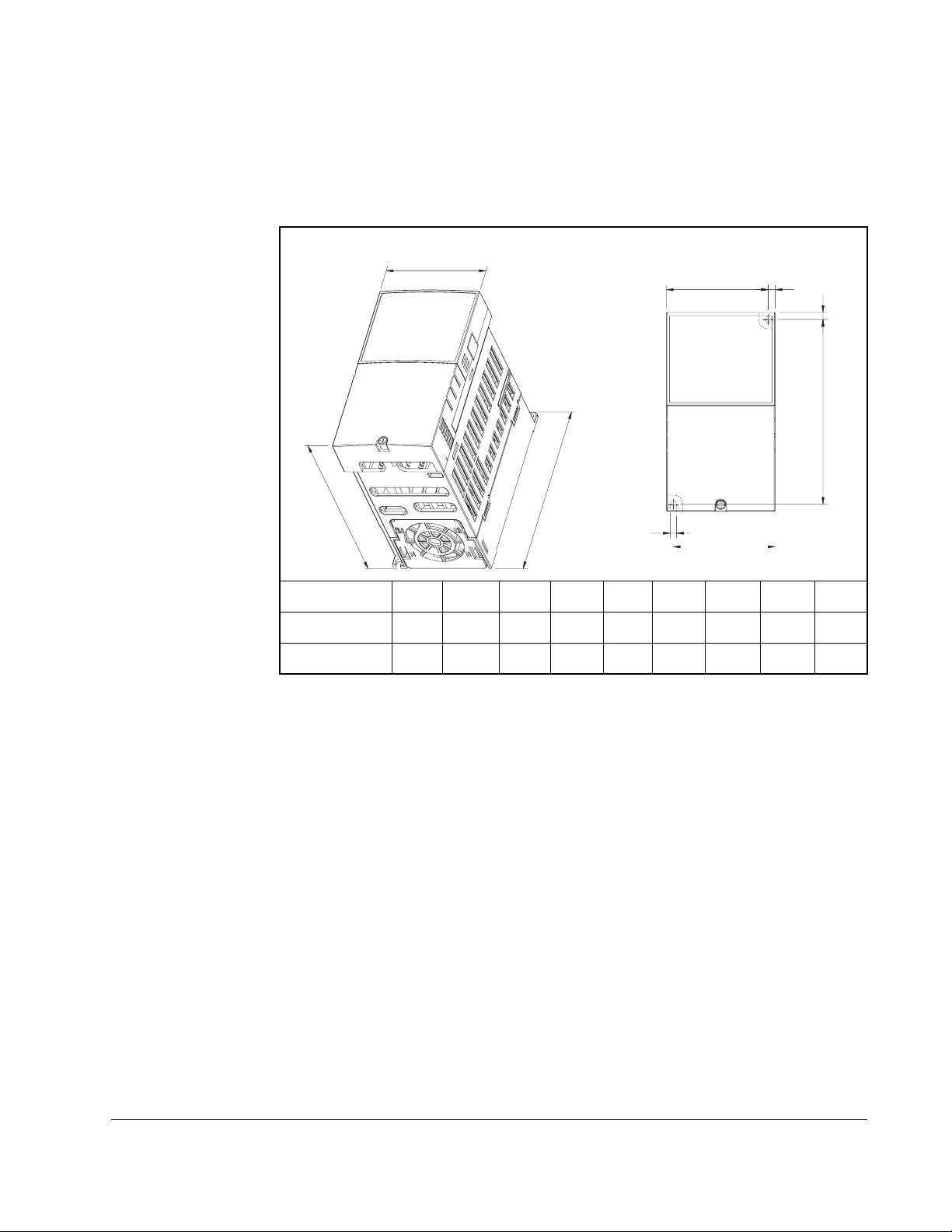
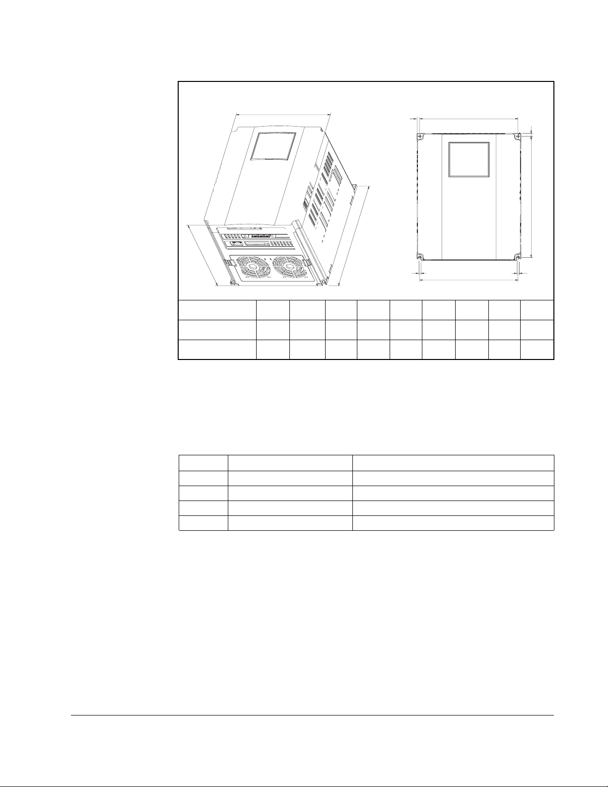
3.1.3 Mounting Dimensions for the VS1MD Drive
Overall dimens ions and weights are illustrated in figures 3.2, 3.3, 3.4 and 3.5 as an aid to
calculating the total area required by the VS1-MD drive. Dimensions are in millimeters. Weights
are in kilograms. See table 2.1 for drive ra tings by frame.
W
H
W1
A
A
H1
D
B
W1
Frame Size A HP W W1 H H1 D A B kg
230V/460V 0.5 70 65.5 128 119 130 4.5 4.0 0.76
230V/460V 1.0 70 65.5 128 119 130 4.5 4.0 0.77
Figure 3.2 – Drive Dimensions and Weights Frame A
Inst alling the Drive 3-3
Page 16
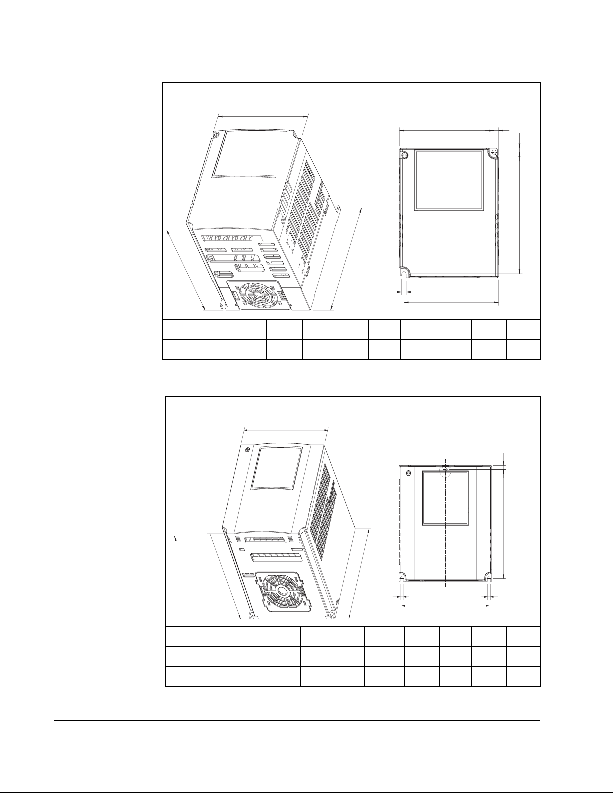
W
W1
A
H1
H
D
B
W1
Frame Size B HP W W1 H H1 D A B kg
230V/460V 2.0 100 95.5 128 120 130 4.5 4.5 1.12
Figure 3.3 – Drive Dimensions and Weights Frame B
A
W
A
H1
D
Frame Size C HP W W1 H H1 D A B kg
230V/460V 3.0 140 132 128 120.5 155 4.5 4.5 1.84
230V/460V 5.0 140 132 128 120.5 155 4.5 4.5 1.89
Figure 3.4 – Drive Dimensions and Weights Frame C
H
B
W1
B
3-4 VS1MD AC Drive User Manual
Page 17
W
A
W
H1
H
D
B
B
W1
Frame Size D HP W W1 H H1 D A B kg
230V/460V 7.5 180 170 220 210 170 5.0 4.5 3.66
230V/460V 10.0 180 170 2 20 210 170 5.0 4.5 3.66
Figure 3.5 – Drive Dimens ions and Weights Frame D
A
3.2 Mounting the Drive
Mount the drive upright on a flat, vertical, and level surface.
Table 3.1 – Mounting Speci fications
Frame Screw Size Screw Torque
A M3.5 (#6-32) 0.67 - 0.97 N-m (6 - 8 in-lb)
B M4 (#8-32) 1.56 - 1.96 N-m (14 -17 in-lb)
C M4 (#8-32) 1.56 - 1.96 N-m (14 -17 in-lb)
D M4 (#8-32) 1.56 - 1.96 N-m (14 -17 in-lb)
3.2.1 Protecting the Drive from Debris
The drive must be protected from debris falling through the vents in the top of the drive
during installation and operation. The drive is designed to operate in IP20/Open Type
application mounted in a protective enclosure. A conduit kit is available as an option
which provides a top panel to block the top vents and prevent debris from entering the
drive.
Inst alling the Drive 3-5
Page 18

3.3 Watts L oss Data
Model # HP Fr ame Wat ts Loss
VS1MD20P5 0.5 A 13
VS1MD21 1.0 A 28
VS1MD22 2.0 B 18
VS1MD23 3.0 C 56
VS1MD25 5.0 C 98
VS1MD27 7.5 D 73
VS1MD210 10.0 D 70
VS1MD40P5 0.5 A 9
VS1MD41 1.0 A 22
VS1MD42 2.0 B 32
Table 3.2 – Watts Loss Data
230 Volts
460 Volts
VS1MD43 3.0 C 47
VS1MD45 5.0 C 94
VS1MD47 7.5 D 84
VS1MD410 10.0 D 113
3-6 VS1MD AC Drive User Manual
Page 19
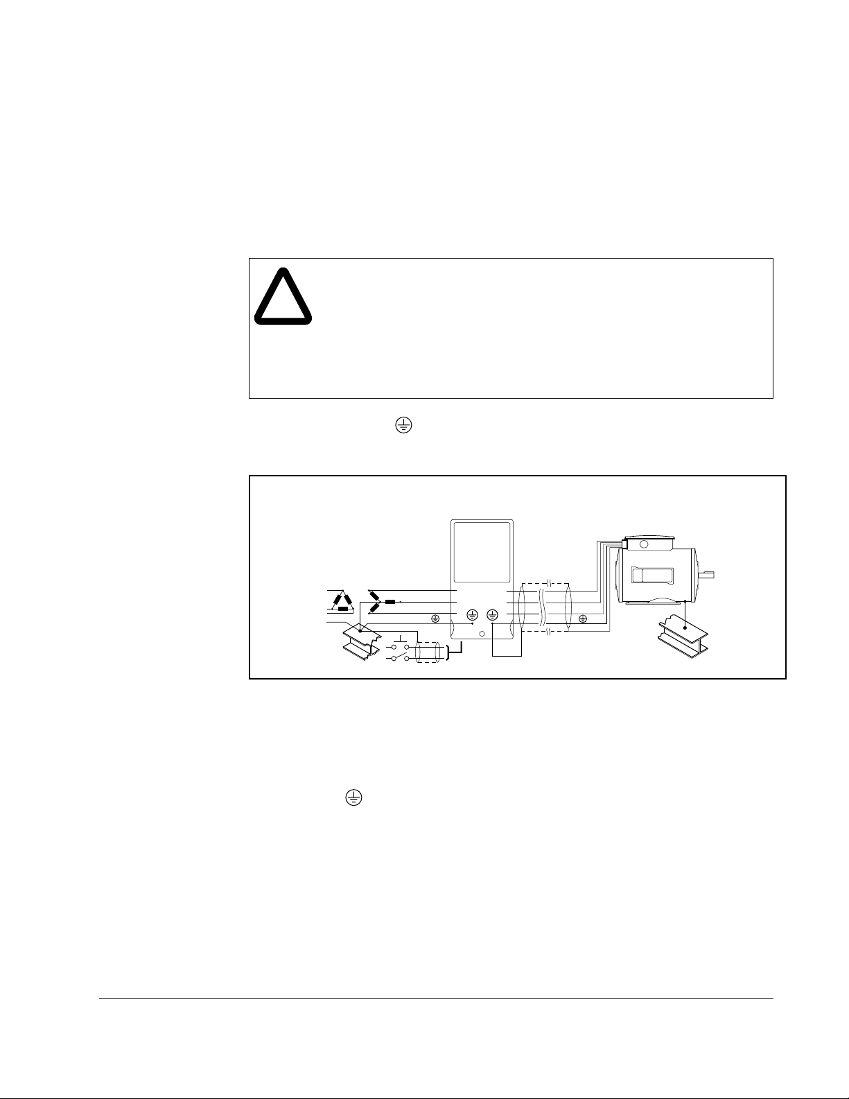
4.1 Grounding the Drive
ATTENTION:T he following information is merely a guide for proper
installation. Baldor Electric Company cannot assume responsibility for
!
The drive Safety Ground - must be connected to system ground. Ground impedance must
conform to the requirements of national and local indust ri al safety regulations and/or electrical
codes. The integr ity of all ground conne cti ons should be periodically checked.
the compliance or the noncompliance to any code, national, local or
otherwise for the proper installation of this drive or associated equipment.
A hazard of personal injury and/or equipment damage exists if codes are
ignored during installation.
ATTENTION:Use the dedicated ground terminal to ground the drive. Do
not use the screw in the case or chassis, etc for grounding.
CHAPTER 4
Power Wiring
R
S
T
SHLD
Figure 4.1 – Typical Grounding
Ground Fault Monitoring
If a system ground fault monitor is to be used, only Type B devices should be used to
avoid nuisance tripping.
Safety Ground -
This is the safety ground for the drive that i s requi red by code. One of these points must be
connected to adjacent building steel (girder, joist), a floor ground rod, or bus bar. Grounding
points must comply with national and loc al i ndustrial safet y regulations and/or electrical codes.
Motor Ground
The motor ground must be connected to one of the ground terminals on the drive.
U
V
W
Power Wiring 4-1
Page 20

Shield Terminat io n - SH L D
Either of the safety ground termi nals provides a grounding point for the motor cable shiel d. The
motor cable shield connected to o ne of these term inal s (drive end) sho uld al so be connect ed to
the motor frame (motor end). Use a shield terminating or EMI clamp to connect the shield to the
safety ground te rminal.
When shielded cable is used for control and signal wiri ng, t he shield should be grounded at
the source end only, not at the drive end.
4.1.1 RFI Filter Grou nding
Using drives with RFI fi lter s may resul t in relat ivel y high gr ound leak age cu rrent s. The refor e, the
filter must only be used in installations with grounded AC supply systems and be
permanently installed and solidly grounded (bonded) to the buildi ng power distribution
ground.
Ensure that the incom ing supply neutral is solidly connected (b onded) to the same building
power distribution ground. Groundi ng m ust not rely on flexible cables and should not include
any form of plug or sock et that would permit inadvertent disconnection. Some local codes may
require redundant ground connections. The integrity of all connections should be periodically
checked.
4.1.2 Grounding Procedure
Step 1. Remove the front cover.
Step 2. Connect the Grounding wire to the ground terminal through the opening for
ground terminal. Enter the screw driver from vertical to the terminal and
secure the screw tightly.
4.1.3 Grounding Guidelines
200V Class 400V Class
Inverter
capacity
0.5 HP 3.5 mm
1.0 HP 3.5 mm
2.0 HP 3.5 mm
3.0 HP 3.5 mm
7.5 HP 5.5 mm
Wire
size
2
2
2
2
2
Terminal
screw
M3 Type 3 2 mm
M3 2 mm
M3 2 mm
M3 2 mm
M4 3.5 mm
Table 4.1 – Grounding G uidelines
Grounding
method
Wire
size
2
2
2
2
2
Terminal
screw
Grounding
method
M3 Special Type 3
M3
M3
M3
M4
4-2 VS1MD AC Drive User Manual
Page 21

4.2 Connecting Peripheral Devi ces to the VS1MD Drive
ATTENTION:Appropria te peripheral devices must be selected and
correct connections made to ensure proper operation. You must read and
understand this manual thoroughly before proceeding. Failure to observe
!
this precaution could result in damage to, or destruction of, the equipment.
The following devices are required to operate the VS1MD drive.
Table 4.2 – Peripheral Devices for the VS1MD Drive
AC Source Supply Use a power supply within the
permissible range for the drive’s
input power rating.
MCCB or Earth leakage
circuit breaker (ELB)
Magnetic Contactor Install a magnetic contactor if
Reactors Reactors must be used when the
Installation and wiring To ensure optimal operation and
Select circuit breakers with care. A
large inrush current may flow in the
converter when power is turned on.
necessary. When installed, do not
use the contactor for the purpose of
starting or stopping.
power factor needs to be improved
or the drive is installed within 10 m
of a large power supply system
(1000kVA or more).
life span of the drive, install it in an
approriate place with proper
orientation and clearances.
Incorrect terminal wiring can result
in damage to the equipment.
To motor Do not connect a power factor
capacitor , surge suppresor , or radio
noise filter to the output side of the
drive.
Power Wiring 4-3
Page 22

4.3 Power Terminal Wiring
3KDVH$&
9ROWDJHLQSXW
5DWHGLQSXW
9 ROWDJH
5HVL VW R U
0RWRU
'%
5
AC Line
6
Voltage
input
7
DB
%
%
reistor
connect
terminal
8
Motor
connect
9
terminal
:
Ground
*
5
ion
6
7
ion
*
Figu re 4.2 – Power Terminal Wi ring
% %
8
9
:
*
4-4 VS1MD AC Drive User Manual
Page 23
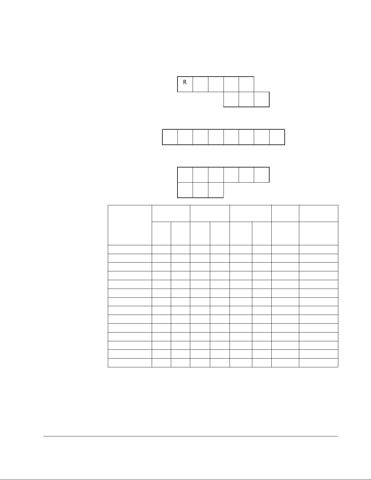
4.4 Specifications for Power Terminal Block Wiring
VS1MD20P5, VS1MD21, VS1MD40P5, VS1MD41, VS1MD22, VS1MD42
RSTB1B2
UVW
VS1MD23, VS1MD43, VS1MD25, VS1MD45
RSTB1B2UVW
VS1MD27, VS1MD210, VS1MD47, VS1MD41 0
B1 B2 U V W
RST
Model
Number
VS1MD20P5
VS1MD21
VS1MD22
VS1MD23
VS1MD25
VS1MD27
VS1MD10
VS1MD40P5
VS1MD41
VS1MD42
VS1MD43
VS1MD45
VS1MD47
VS1MD410
R,S,T
wire size
2
AWG
mm
2 14 2 14 3.5 12 M3.5 10/ 8.7
2 14 2 14 3.5 12 M3.5 10/ 8.7
2 14 2 14 3.5 12 M3.5 10/ 8.7
2 14 2 14 3.5 12 M4 15/13
3.5 12 3.5 12 3.5 12 M4 15/13
5.5 10 5.5 10 5.5 10 M5 32/28
8 8 8 8 5.5 10 M5 32/28
2 14 2 14 2 14 M3.5 10/8.7
2 14 2 14 2 14 M3.5 10/8.7
2 14 2 14 2 14 M4 15/13
2 14 2 14 2 14 M4 15/13
2 14 2 14 2 14 M4 15/13
3.5 12 2 14 3.5 12 M5 32/28
3.5 12 3.5 12 3.5 12 M5 32/28
U, V, W
wire size
2
mm
AWG
Ground Wire Screw
size
2
mm
AWG Terminal
Screw
Size
Terminal
torque
Screw
Torque
(Kgf.cm/lb-in)
* Strip the sheaths of the wire insulation 7mm when a ring terminal is not used for
power connection.
Power Wiring 4-5
Page 24

4.5 Recommended Breakers
Table 4.3 – Circuit Brea ker Ratings by Model Number
Model Breaker Model Breaker
Current[A] Voltage[V] Current[A] Voltage[V]
VS1MD20P5
VS1MD21 30 230
VS1MD22 30 230
VS1MD23 30 230
VS1MD25 30 230
VS1MD27 50 230
VS1MD10 60 230
30 230
VS1MD40P5 30 460
VS1MD41 30 460
VS1MD42 30 460
VS1MD43 30 460
VS1MD45 30 460
VS1MD47 30 460
VS1MD410 30 460
4.6 Recommended Fuses and AC Reactors
Model External fuse AC reactor
Current[A] Voltage[V]
VS1MD20P5
VS1MD21 10 A 500 2.13mH, 5.7A
VS1MD22 15 A 500 1.20mH, 10A
VS1MD23 25 A 500 0. 88m H,14A
VS1MD25 40 A 500 0.56mH, 20A
VS1MD27 40 A 500 0.39mH, 30A
VS1MD210 50 A 500 0.28mH, 40A
VS1MD40P5 5 A 500 18.0mH, 1.3A
VS1MD41 10 A 500 8.63mH, 2.8A
VS1MD42 10 A 500 4.81mH, 4.8A
VS1MD43 10 A 500 3.23mH, 7.5A
VS1MD45 20 A 500 2.34mH, 10A
VS1MD47 20 A 500 1.22mH, 15A
VS1MD4100 30 A 500 1.14mH, 20A
10 A 500 4.20mH, 3.5A
ATTENTION:Suitable For Use On A Circuit Capable Of Delivering
Not More Then 65,000 RMS Symmetrical Amperes. 240V drives
!
4-6 VS1MD AC Drive User Manual
or 480V drives Volts Maximum
ATTENTION:Use Class H or K5 UL Listed Input Fuse and UL
Listed Breaker Only. See the table above for the voltage and current
rating of the fuse and the breaker.
Page 25

4.7 Reflected Wave Protection
When more than one motor is connected to one inverter, total wiring length should be
less than 200m (656ft). Do not use a 3-wire cable for long distances. Due to increased
leakage capacitance between wires, over-current protective feature may operate or
equipment connected to the output side may malfunction. In case of long wire length,
lower carrier frequency or contact Baldor for recommendations.
Table 4.4 – Wire Length Recommendations
Length Between Inverter and Motor Allowable Carrier Frequency
Up to 50 meters Less than 15 kHz
Up to 100 meters Less than 5 kHz
More than 100 meters Less than 2.5 kHZ
Power Wiring 4-7
Page 26

4-8 VS1MD AC Drive User Manual
Page 27
CHAPTER 5
Control Wiring
This chapter describes how to wire the signal and I/O terminal strip for stop, speed
feedback, and remote control signals.
ATTENTION:Apply the rated torque to terminal screws. Loose screws
can cause short circuit and malfunction. Tightening the screws too much
!
can damage the terminals and cause short circuit and malfunction.
ATTENTION:Make sure the input power is off before wiring.
ATTENTION:After power supply is switched off following operation, wait
at least 10 minutes after LED keypad display is off before you start
working on it.
ATTENTION:Applying input power supply to the output terminals U, V
and W causes internal inverter damage.
ATTENTION:Use ring terminals with insulated caps when wiring the
input power and motor wiring.
ATTENTION:Do not leave wire fragments inside the inverter. Wire
fragments can cause faults, breakdowns and malfunctions.
ATTENTION:When more than one motor is connected to one inverter,
total wiring length should be less than 200m (656ft). Do not use a 3-wire
cable for long distances. Due to increased leakage capacitance between
wires, over-current protective feature may operate or equipment
connected to the output side may malfunction. In case of long wire
length, lower carrier frequency or contact Baldor for recommendations.
ATTENTION:Never short B1 and B2 terminals. Shorting terminals may
cause internal inverter damage.
ATTENTION:Do not install a power factor capacitor, surge suppressor
or RFI filter in the output side of the inverter. Doing so may damage
these components.
5.1 Stop Circuit Requirements
ATTENTION:You must provide an external, hardwired emergency
stop circuit outside of the drive circuitry. This circuit must disable the
!
In addition to the operational stop, you must provide a hardwired emergency stop
external to the drive. The emergency stop circuit must contain only hardwired
electromechanical components. Operation of the emergency stop must not depend on
electronic logic (hardware or software) or on the communication of commands over an
electronic network or link. Note that the hardwired emergency stop you install can be
used at any time to stop the drive.
Control Wiring 5-1
system in case of improper operation. Uncontrolled machine
operation can result if this procedure is not followed. Failure to observe
this precaution could result in bodily injury.
Page 28

5.2 Motor Start/Stop Precautions
ATTENTION:A contactor or other device that routinely disconnects and
reapplies the AC line to the drive to start and stop the motor can cause
!
Important points to remember about I/O wiring:
• Always use copper wire.
• Wire with an insulation rating of 600V or greater is recommended.
• Control and signal wires should be separated from power wires by at least 0.3
meters (1 foot).
drive hardware damage. The drive is designed to use control input
signals that will start and stop the motor. If used, the input device must
not exceed one operation per minute or drive damage can occur. Failure
to observe this precaution can result in damage to, or destruction of,
equipment.
ATTENTION:The drive start/stop control circuitry includes solid-state
components. If hazards due to accidental contact with moving
machinery or unintentional flow of liquid, gas or solids exist, an
additional hardwired stop circuit may be required to remove the AC line
to the drive. When the AC line is removed, there will be a loss of any
inherent regenerative braking effect that might be present - the motor
will coast to a st op . A n a ux iliary brakin g method may b e required.
Important: I/O terminals labeled “Common” are not referenced to the safety ground
terminal and are designed to greatly reduce common mode interference.
ATTENTION:Driving the 4-20 mA analog input from a voltage source
could cause component damage. Verify proper configuration prior to
!
applying input signals.
5-2 VS1MD AC Drive User Manual
Page 29
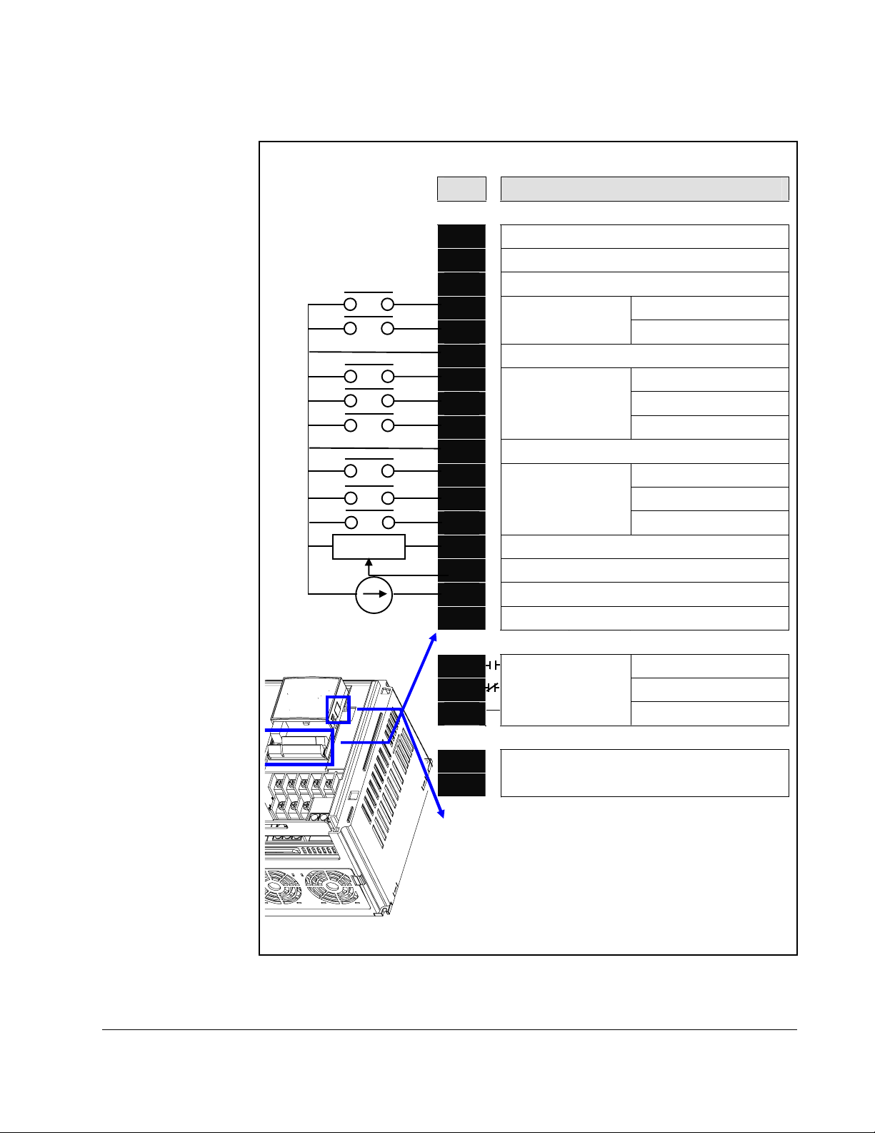
5.3 Terminal Wiring (Control I/O)
T/M Description
MO Multi-function open collector output
MG MO Common
24 24V output
P1 FX: F orw ard run
P2
CM Input signal common
P3 BX: Stop
P4 RST: Trip reset
P5
CM Input signal common
P6
P7
P8
VR 10V power supply for potentiometer
V1 Freq. Setting Voltage signal input: -0~10V
G
I Freq. Setting Current signal input: 0~20mA
AM Multi-function analog output signal: 0~10V
MF input terminal
(factory setting)
MF input terminal
(factory setting)
MF input terminal
(factory setting)
RX: Reverse run
JOG: Jog operation
Preset Speed Input 1
Preset Speed Input 2
Preset Speed Input 3
3A A contact output N.O.
3B B contact output N.C.
3C
S+
S-
Multi-function relay
output terminal
A/B contact common
RS485 communication terminal
# For connection to Remote Option or
parameter copying
Control Wiring 5-3
Page 30

5.4 Control Terminal Specificati ons
MO MG 24 P1 P2 CM P3 P4 S- S+
3A 3B 3C P5 CM P6 P7 P8 VR V1 I AM
T/M Terminal Description
P1
Multi-fu nction d igital input
to
P8
CM Common Terminal 1.0 1.5 M2.6 0.4
VR Power supply for external
V1 Input terminal f or Voltage
I Input terminal for Current
AM Multi-function analog
MO Multi-function terminal for
MG Ground terminal for
24 24V External Power
3A Multi-function relay
3B Multi-function relay
3C Common for
T/M 1-8
speed potentiometer
operation
operation
output termin al
open collector output
external power supply
Supply
output A contact N.O.
output B contact N.C.
Multi-function relays
Wire size[m m2]
solid
wire
1.0 1.5 M2.6 0.4
1.0 1.5 M2.6 0.4
1.0 1.5 M2.6 0.4
1.0 1.5 M2.6 0.4
1.0 1.5 M2.6 0.4
1.0 1.5 M2.6 0.4
1.0 1.5 M2.6 0.4
1.0 1.5 M2.6 0.4
1.0 1.5 M2.6 0.4
1.0 1.5 M2.6 0.4
1.0 1.5 M2.6 0.4
stranded
Screw
size
Torque
[Nm]
Specification
Output Voltage: 12 V
Max output current: 10mA
Potentiometer: 1 - 5 kohm
Max input voltage:
-12V - +12V input
0 - 20 mA input
Internal Resister: 250 ohm
Max output voltage: 11 V
Max output current:
100mA
Below DC 26V, 100mA
Max output current:
100mA
Below AC 250V, 1A
Below DC 30V, 1A
5-4 VS1MD AC Drive User Manual
Page 31

5.5 Source/Sync for Input Control Wiring
1. When using DC 24V inside inverter [Source]
SW S8
SW S8
S8
CM
RG
P1
CM
(inside inverter)
2. When using external DC 24V [Sink ]
SW S8
S8
DC24V
CM
P1
CM
( ins i de inv e rt e r)
RG
Source
(NPN)
DC 24 V
CPU
RG
CM
Sink (PNP)
DC 24 V
CPU
R
CM
Control Wiring 5-5
Page 32

5.6 I/O Wiring Recommendations
Table 5.1 – Recommended Control and Sign al Wire
Wire Type(s) Description
Belden 8760/9460
(or equiv.)
Belden 8770
(or equiv.)
1
If the wires are short and contained within a cabinet that has no sensitive circuits,
0.8 mm
0.8 mm
only.
2
(18AWG), twisted pair, 100% shield with drain.
2
(18AWG), 3 conductor, shielded for remote pot
the use of shielded wire may not be necessary, but is always recommended .
Table 5.2 – I/O Terminal Block Specifications
Maximum Wire Size1
2
1.3 mm
1
Maximum / minimum that the terminal block will accept. These are not
(16 AWG) 0.13 mm2 (26 AWG)
Minimum Wire Size
1
0.5 to 0.8 Nm
(4.4 in-lb to 7 in-lb)
recommendations.
5.6.1 Maximum Control Wire Length Recommendations
1
Minimum
Insulation
Rating
300 V
75° C
(167° F)
Torque
Do not exceed control wiring length of 30 meters (100 feet). Control signal cable
length is highly dependent on electrical environment and installation practices. To
improve noise immunity, the I/O terminal block Common must be connected to ground
termi n al/protective e a r th .
5.7 Technical Specifications
Please see Appendix A - Technical Specifications for detailed electrical information.
5-6 VS1MD AC Drive User Manual
Page 33

Factory-default parameter values allow the drive to be controlled from the integral
keypad. No programming is required to start, stop, change direction, or control speed
directly from the integral keypad.
This chapter provides an overview of the integrated keypad and how to use it to
program the VS1MD drive.
6.1 Keypad Components
CHAPTER 6
Using the Keypad
1
2
Refer to table 6.1 for the LED descriptions noted by
6.1.1 Display Descript ion
The alpha-numeric display indicates the following:
• Operational Values (such as Output Frequency)
3
4
➊ through ➍ and table 6.2 for key definitions.
• Parameter Numbers
• Parameter Values
• Fault Codes
Using the Keypad 6-1
Page 34

6.2 LED Descriptions
Refer to figure 6.1 for the location of the LEDs described in table 6.1.
No. LED LED State Description
PROG Steady Red (On) Indicates the drive is in programming mode.
➊
(Off) Indicates the drive is in operational Mode.
RUN Steady Red (On) Indicates the drive is running at commanded speed.
➋
Flashing Red Indicates dri ve is accelerating or decelerating to new
(Off) Drive is not running.
FWD Steady Red (On) Indicates the drive is in forward operation.
➌
(Off) Indicates the drive is in reverse operation.
STP/FLT Steady Red (On) Indicates the drive is in a stopped position.
➍
Flashing Red Indicates the drive is faulted.
(Off) Drive is running.
6.3 Key Descriptions
Table 6.1 – LED D escriptions
speed setting.
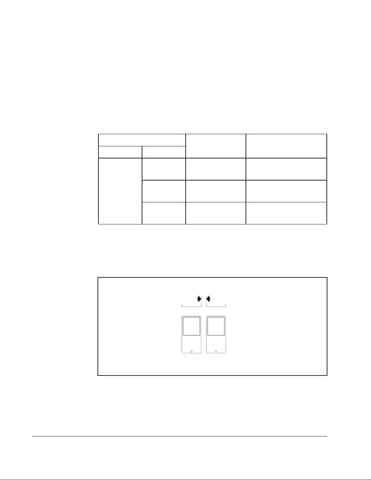
Refer to figure 6.1 for the location of the keys described in table 6.2.
Table 6.2 – Key Descriptions
Key Name Description
Run Key
• Starts the drive.
• Active when the input mode is programmed for
keypad control.
St op Key
• Stop s the drive in programmed stop mode.
• Always active.
• Rese t active faults .
Ent/Prog Key
• Accesses programming m enu and locks in
changed values.
• To enter programming mode, the Ent/Prog key
must be held in for 2 seconds.
• Holding the Ent/Prog key for 2 sec onds or mo re will
escape back to Control Reference Mode or back
out of a parameter edit f unction.
6-2 VS1MD AC Drive User Manual
Page 35

T able 6.2 – Key Descriptions (Continued)
Key Name Description
Speed
Reference
Keys
Operation Mode:
• Changes the commanded speed r eference.
• Only active when the input mode is programmed for
keypad control.
• The Up-Arrow increases the speed reference at a
controlled rate.
• The Down-Arrow decre ases the s peed r efere nce at
a controlled r ate.
• Holding either arrow for a set period of time will
increase the ref erence ramp rate.
Program Mode:
• Increment / Decrement parameter numbers or
parameter values
Direction
Keys
Operation Mode:
• Only active when the input mode is programmed for
keypad control.
• Direction keys are active only when operating in
reference command mode.
• Reverse may also be disabl ed by a parameter .
6.4 About Parameters
To program the drive for a specific application, you adjust the appropriate param eters. The
paramete rs ar e used to define character istics of the drive.
There are three types of parameters:
• Numbered List Parameters (Enumerated Parameters)
Numbered list param eters allow a selection from two or more options. Each item is
represented by a number.
Example: Start/Stop Source (P38)
• Bit Par a me ters
Bit parameters have individual bits associated with features or conditions. If the bit is 0, the
feature is off or the condition is false. If the bit is 1, the feature is on or the co ndition is true.
Example: Terminal Status Display (d7)
• Numeric Parameters
These parameters have a single numerical value (for example, 0.1 volts).
Example: Motor Rated Current (P32)
Program Mode:
• Cycle through the parameter groups or shift to
the next digit to be changed while in the
parameter edit mode.
Parameters are al so either configurable or tunable, or read-onl y.
Configurable p arameters can be adjusted or changed only while the drive is stopped.
Using the Keypad 6-3
Page 36

T unable parameters can be adjusted or changed whil e the dr ive is running or stopped.
Read-only parameters cannot be adjusted.
6.5 How Parameters are Organized
Parameters are organized into five Parameter Groups:
• The Display Parameter Group (dnn) contains parameters for the display of basic
drive information.
• The Programming Parameter Group (Pnn) contains the most commonly used
parameters for startup and operation.
• The T erminal Parameter Group (tnn) contains a linear list of input and output control
parameters.
• Function Group 1 Parameters (Fnn) contains a linear list of advanced motor control
parameters.
• Function Group 2 Parameters (Hnn) contains a linear list of advanced motor profile
parameters.
6.6 Moving Between Parameter Groups
Use the following procedure to enter the programming mode and to move between
groups:
Table 6.3 – Moving Betwee n Parameter Group s
Procedure Sample Display
Step 1. When the drive first powers up, the display will
indicate the value of the “Power ON Display,” which
is defined in Parameter H72. The default “Power On
Display” is the commanded frequency.
Step 2. Press and hold down the ENTER key for at least two
seconds to change the drive from the operation
mode to the programming mode.The “PROG” LED
will illuminate indicating that the drive is in
programming mode. The drive will display the first
parameter of the “Display” group.
Step 3. Press the right arrow key to change to the
“Parameters Group”.
Step 4. Press the right arrow key to change to the “Terminal
Group”.
6-4 VS1MD AC Drive User Manual
Page 37

Table 6.3 – Moving Between Paramet er Group s
Procedure Sample Display
Step 5. Press the right arrow key to change to “Function
Group 1”.
Step 6. Press the right arrow key to change to “Function
Group 2”.
Step 7. Press the right arrow key to change to “Display”
group.
Step 8. Press and hold down the ENTER key for at least two
seconds to change the drive from the programming
mode back to operation mode.The “PROG” LED will
go out indicating that the drive is in operation mode.
The drive will display the default “Power On Display”.
Note that the above can be execute in reverse order by using the left arrow key
instead of the right arrow key.
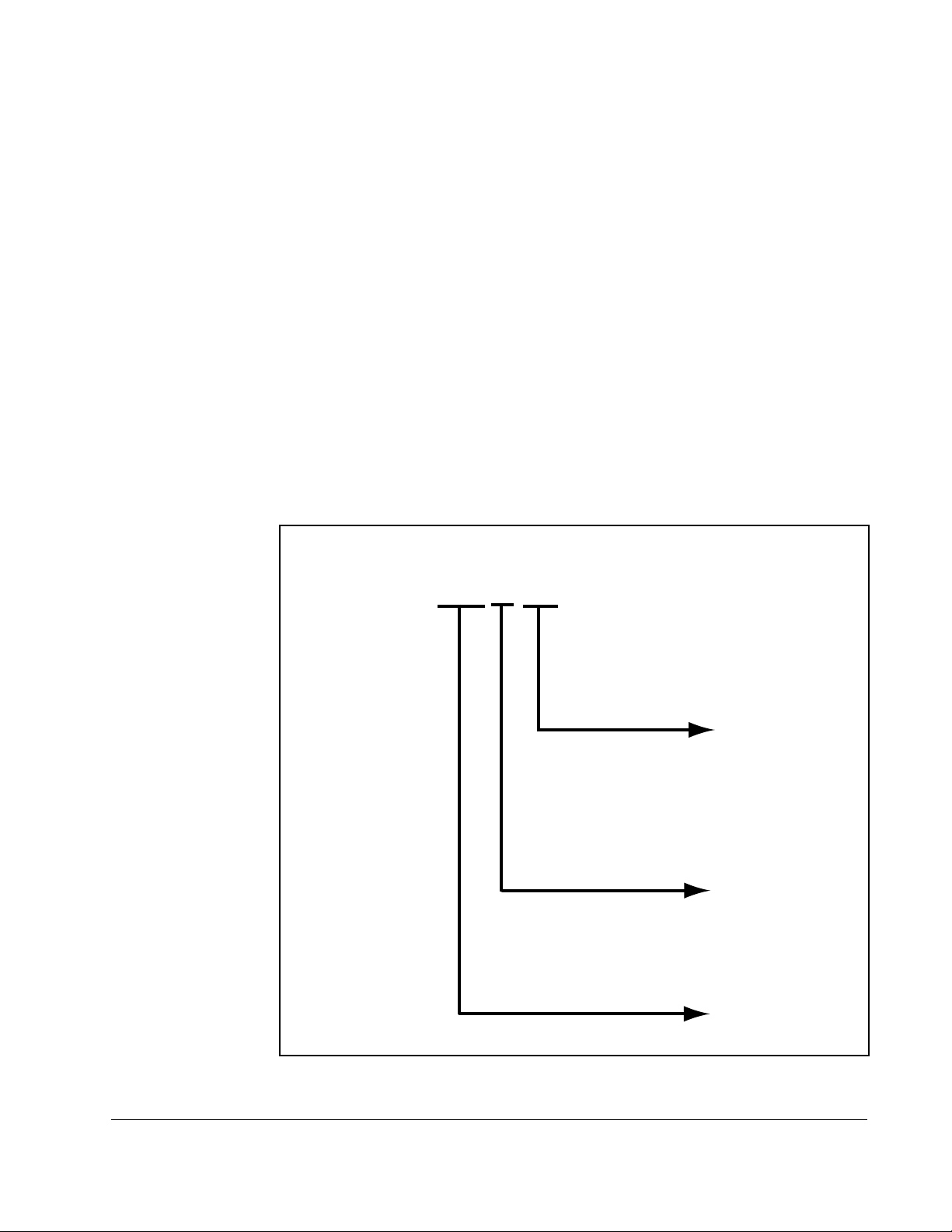
Y ou can only move between groups while the first parameter of the group is displayed.
Pressing the left or right arrow while displaying any parameter other than the first
parameter of the group returns to the first parameter of the group.
Pressing the
up or down
Terminal group
arrow mo ves
you within a
group of
parame ters
Function Group 1
Function Group 2
Pressing the
left or righ t
arrow from
any parameter
returns you to
the firs t
parameter of
the grou p
Using the Keypad 6-5
Page 38

The below example indicates the steps needed to move from parameter F35 to
Function Group 2.
Table 6.4 – Moving from F35 to Func tion Group 2
Procedure Sample Display
Step 1. When a parameter other than the first in a group is
displayed, you must initially go to the first parameter
of the group prior to going to the next group. For this
example, parameter F35 of Function Group 1 is
currently displayed and you want to go to Function
Group 2 (H Parameters).
Step 2. Press the left or right arrow and parameter F0 will be
displayed.
Step 3. Press the right arrow key to change to “Function
Group 2”.
6.7 Changing Between Parameters Within a Group
Each group contains parameters arranged in a linear list. The list can be navigated
using the Up and Down arrows.
Table 6.5 – Changing Between Parameters Withing a G roup
Procedure Sample Display
Step 1. From the operation mode, press and hold down the
ENTER key for at least two seconds to change the
drive to the programming mode. The “PROG” LED
will illuminate indicating that the drive is in
programming mode. The drive will display the first
parameter of the “Display” group.
Step 2. Press the up arrow to display the next parameter.
Step 3. Press the up arrow again to display the next
parameter, continue until the desired parameter is
displayed.
Note that using the down arrow allows navigation through the parameters in
reverse order.
6-6 VS1MD AC Drive User Manual
Page 39

The first parameter of each group, with the exception of the “Display Group”, is a
special parameter called a “Jump Code”. The parameter can be used to jump to a
specific parameter within a group without having to scroll through the parameters
using the up and down arrows. Once the Jump Code is programmed, the drive will
save the setting for future use, but this can always be reprogrammed to jump to a
different parameter.
The following exam ple illustrates the use of a Jump Code to jump to parameter P38.
Table 6.6 – Using the Jump Code
Procedure Sample Display
Step 1. From the operation mode, press and hold down the
ENTER key for at least two seconds to change the
drive to the programming mode. The “PROG” LED
will illuminate indicating that the drive is in
programming mode. The drive will display the first
parameter of the “Display” group.
Step 2. Press the right arrow to change to the “Parameters”
group.
Step 3. Press the ENTER key to edit P0 (Jump Code).
Step 4. Press the UP arrow seven times until the display
indicates an “8”.
Step 5. Press the left arrow one time such that the next digit
is displayed. It will be displayed brighter than the
previous digit.
Step 6. Press the UP arrow three times such that the display
indicates the parameter number.
Step 7. Press the ENTER key to accept the value. The value
will be saved in the Jump Code (P0) for future use
and the desired parameter will immediately be
displayed.
Using the Keypad 6-7
Page 40

The following example shows how to use a previously stored Jump Code.
Table 6.7 – Using a Previ ously Stored Jump Code
Procedure Sample Display
Step 1. From the operation mode, press and hold down the
ENTER key for at least two seconds to change the
drive to the programming mode. The “PROG” LED
will illuminate indicating that the drive is in
programming mode. The drive will display the first
parameter of the “Display” group.
Step 2. Press the right arrow to change to the “Parameters”
group.
Step 3. Press the ENTER key to access the Jump Code.
Step 4. Press the ENTER key a second time and the desired
paramete r w ill b e d is played.
6.8 Modifying the Value of a Parameter
The parameters located in the Display group are read-only and can not be modified.
All other parameters (with a few exceptions) can be modified by the user. Some
parameters are configurable - meaning that the drive must be stopped before the
parameter can be modified, while others are tunable - meaning that the parameter can
be modified while the drive is stopped or running.
6-8 VS1MD AC Drive User Manual
Page 41

The following example shows how to modify the acceleration time located in
parameter P 4 1.
Table 6.8 – Modifying Parameter Values
Program Group
Step 1. From the operation mode, press and hold down the
ENTER key for at least two seconds to change the
drive to the programming mode. The “PROG” LED
will illuminate indicating that the drive is in
programming mode. The drive will display the first
parameter of the “Display” group.
Step 2. Press the right arrow key to change to the
“Parameters” group.
Step 3. Use the up arrow or the jump code to display the
acceleration time parameter P41.
Step 4. Momentarily press the ENTER key to begin the
parameter value edit mode. Notice that the tenths
digit is highlighted for editing. At this point you can
use the up arrow key to increment the value all the
way to the new setting (16.0 in this example) or
proceed with the following steps.
Step 5. Press the left arrow key to select the ones digit for
editing.
Step 6. Press the up arrow key to increment the ones digit
from a 5 to a 6.
Step 7. Press the left arrow key to select the tens digit for
editing.
Step 8. Press the up arrow key to increment the tens digit
from a 0 to a 1.
Using the Keypad 6-9
Page 42

Table 6.8 – Modifying Parameter Values
Step 9. Press the ENTER key to accept the value and the
display will begin to flash so that you can confirm the
entry.
Step 10. Press the ENTER key a second time to acknowledge
the entry. The display will revert to showing the
parameter number.
6.9 Monitoring Display Parameters
The Display group is a group that consists of read only values that can be monitored
by the user to diagnose the operation of the drive and motor. To monitor the motor
current, follow the below example.
Table 6.9 – Monitoring Display Parameters
Display Group
Step 1. From the operation mode, press and hold down the
ENTER key for at least 2 seconds to change the
drive to the programming mode. The “PROG” LED
will illuminate indicating that you are in the
programming mode. The drive will display the first
parameter of the “Display” group.
Step 2. Press the up arrow key twice to change to the
parameter d2 (Motor Current).
Step 3. Momentarily press the ENTER key to display the
motor current. The display will be updated in real
time.
Step 4. Press the ENTER key to return to the previous
display so that you can select a new parameter to
view.
6-10 VS1MD AC Drive User Manual
Page 43

6.10 Reviewing the Fault Status in the Display Group
When a fault is active, this is annunciated on the drive by flashing the STOP/FAULT
LED. This procedure is used to review the active fault as well as certain conditions at
the time the fault occurred.
Table 6.10 – Reviewing Fault Status in the Display Group
Over-
current
trip
Display Gr oup
STOP
RESET
Step 1. When an overcurrent condition has been detected by
the drive, a fault will be latched and the display will
show the condition.
Step 2. Press the ENTER key to see the frequency at which
the fault occurred. This example indicates that the
drive was outputting 30.00 Hz when the fault
occurred.
Step 3. Press the up arrow to view the output current during
the fault. This example indicates that the drive was
outputting 5.0 Amps when the fault occurred.
During
Accel
Current
Frequency
Step 4. Press the up arrow key again to view the operating
status of the drive when the fault occurred. This
example indicates that the drive was accelerating
when the fault occurred.
Step 5. Press the STOP/RESET button on the keypad to
reset the fault and the STOP/FAULT LED will
illuminate solid indicating that the fault is cleared and
that the drive is in the stopped condition. The display
will indicate that there is no longer a fault condition.
Using the Keypad 6-11
Page 44

6.11 Resetting the Parameters to Factory Default
Follow the below procedure to reset the parameters to the factory default values:
Table 6.11 – Resetting Parameters to Factory Default
Function Group 2
Step 1. Navigate to the Function Group 2 (H Group).
Step 2. Press the ENTER key to edit the jump code. Modify
the jump code to be equal to 93.
Step 3. Press the ENTER key to jump to parameter H93.
Step 4. Press ENTER to display the current value of
parameter H93 (it will be 0 indicating that parameters
will not be reset).
Step 5. Press the up arrow key to change the value to a 1.
Step 6. Press the ENTER key to reset the drive parameters
to factory default. The display will revert back to
displaying the parameter number.
6-12 VS1MD AC Drive User Manual
Page 45

7.1 Overview
The following information is provided for each parameter listed in table 7.1 along with
its descripti on:
Parameter Numb er: Unique number assigned to each parameter.
Parameter Name: Unique nam e assig ned to each parameter.
LED Display: Display shown on LED screen when parameter is
Range: Predefined parameter limits or selections. Note that
Default: Factory default setting.
CHAPTER 7
P arameter Desc riptions
accessed.
a negative Hz value indicates reverse rotation.
Access:
• Read Only: Parameter value can not be modified
by user.
• Configurable: Parameter can only be modified
while drive is stopped.
• Tunable: Parameter can be modified while drive
is running or stopped.
Group: Menu group within which parameter is located.
See also: Associated parameters that may provide additional
or relate d in f or mation.
The parameters are presented in numerical order within each of the fivegroups
(Dispay, Basic Parameters, Terminal, Function Group 1, Function Group 2). Appendix
B contains a list of parameters by name cross-referenced to parameter number.
Parameter Descriptions 7-1
Page 46

7.2 Display Group Parameters
Parameters in this group are display only and can be used to monitor drive
conditions. To change th e active display for the drive, use parameter H72 - Power
On Display.
d0 Freq uency Comm and
Range: 0.0 to Frequency High Limit (P36) [Hz]
Default: Read Only
Displays the value of the active frequency command. The commanded
frequency is displayed even if the drive is not running.
d1 Motor R P M
Range: 0.0 Motor RPM (based on P33 Motor
Default: Read Only
Displays the output motor RPM. Motor RPM is scaled based on output
frequency present on terminals U, V and W based on the setting in P33
– Motor Poles.
Poles) [RPM]
d2 Output Current
Range: 0.0 to Motor Rated Current (P32) [Amps]
Default: Read Only
Displays the value of the output current present at terminals U, V and W.
d3 Output Voltage
Range: 0.0 to Drive Rated Voltage [volts]
Default: Read Only
Displays output voltage present at U, V, W.
d4 Outp ut Power
Range: 0.0 to (Drive Rated Power x 2) [kW]
Default: Read Only
Displays the value of the output power present at terminals U, V and W.
7-2 VS1MD AC Drive User Manual
Page 47

d5 Output Torqu e
Range: 0.0 to (Drive Rated Torque x 2) [kgf / M]
Default: Read Only
See Also: H36
Displays the value of the output torque present at terminals U, V and W.
Enter motor efficiency indicated on motor nameplate to H36 to display
correct torque.
d6 DC Li nk Voltage
Range: Based on Drive Rating [Volts DC]
Default: Read Only
Displays the present DC bus voltage level.
d7 Input Terminal status display
Range: See Figure Below
Default: Read Only
Displays the status of the input terminals P1~P8. An example is
shown below for when P1, P3, P4 are ON and P2, P5 are OFF.
33333333
d8 Output termina l status display
Range: See Figure Below
Default: Read Only
Displays the status of the Digital (MO) Output and the Relay
(3A~C) terminals. The following example is for when Digital
Output (MO) is ON and the Relay is OFF.
2 1
2 ))
21
2 ))
$&02
Parameter Descriptions 7-3
Page 48

d9 Software V ersion
Range: 1.0 to 99.9
Default: Read Only
Displays the Main Control Board software version.
nOn Current Fault Display
Range: See Chapter 9 - Troubleshooting for fault
Default: Read Only
See Also: H1-H6
Displays the types of faults, frequency and operating status at the time of
the last fault.
code description
Fault Types
Frequency
Current
Accel/
Decel
Information
Fault during Accel
Fault during Decel
Fault during constant run
Fault code history can be viewed in parameters H1 - H5. H6 is used to
clear the fault code history. For a complete description of fault codes,
refer to Chapter 9 - Troubleshooting.
7-4 VS1MD AC Drive User Manual
Page 49

7.3 Basic Program Group Parameters
The Basic Program Group (P) contains the parameters most commonly used in
start-up.
P0 Jump Code
Range: 30 -4 7
Default:
Access Tunable
Sets the code to jump directly to a specific parameter within the group.
P30 Motor HP Select
Range: 0.5
Default:
Access Configurable
See also:
30
= 0.5 HP
1
= 1 HP
2
= 2 HP
3
= 3 HP
5
= 5 HP
7.5
= 7.5 HP
10
= 10 HP
Preset based on drive rating.
P32 - P34
Sets the motor type connected to the drive output side.
P32 Motor Rated Current
Range: 0.5 - 50 Amps
Default:
Access Configurable
See Also:
Enter motor rated current on the nameplate.
P33 Pole Number
Range: 2, 4, 6, 8, 10, 12
Default:
Access Configurable
See Also:
Select number of motor poles
Preset based on drive rating
P30, P33, P34
4
P30, P32, P34
Parameter Descriptions 7-5
Page 50

P34 Base F requ enc y
Range: 30 - 400 [Hz]
Default:
60
Access Configurable
See Also:
P30, P33, F30-F38
The drive outputs its rated voltage to the motor at this frequency (enter motor
nameplate). See parameter F30 for custom V/Hz settings and V/Hz curve.
P35 Frequency Low Limit
Range: 0 - P36 [ Hz]
Default:
10.0
Access Configurable
See Also:
P36, F30-F38
Sets drive minimum steady state output frequency.
P36 Frequency High Limit
Range: 0 - 400 [Hz]
Default:
60.0
Access Configurable
See Also:
P35
Sets drive maximum steady state output frequency.
P37 Frequency Command
Range: 0 - 400 [Hz]
Default:
0.00
Access Tunable
This parameter manually sets the frequency that the drive is commanded to output.
Set the desired frequency and press ENTER/PROG to lock the value into memory. If
the drive is running, it will immediately accelerate or decelerate to this value once
enter is pressed. If the drive is not running, entering a value in P37 w ill pre-s et the
speed to accelerate to after a valid run command.
7-6 VS1MD AC Drive User Manual
Page 51

P38 Stop/Start Source
Range: 0
1
2
3
Default:
0 {Local OIM)
Access Configurable
See Also:
P40; t1 - t8
Sets the control used to start the drive.
0 Keypad Drive control for start, stop, forward and reverse are from
1Terminal
Operation
2 Drive is controlled from run terminal and directional
3 RS485
Communication
Terminal Operation Mode 1: (2-Wire or 3-Wire Control Fwd/Rev):
= Keypad
= Terminal Mode 1 (2 or 3- wire control for forward/reverse)
= Terminal Mode 2 (2 wire with direction switch)
= RS485 Communication
drive keypad.
Drive is controlled from run forward terminal and run
reverse terminal.
terminal.
Drive operation controlled using RS-485 communications
(see Appendix E).
• Select one digital input (t1~t8) = 0, run forward (FX).
• Select one digital input (t1~t8) = 1, run reverse (RX).
• To enable 3-Wire control select one digital input (t1~t8) = 17, 3-wire
operation.
• Drive stops when both inputs are off or when both inputs are on.
Drive Output
Forward
Digital In
(FX)
Reverse Digit al In (RX)
Parameter Descriptions 7-7
Page 52

P38 Stop/Start Source
Terminal Operation Mode 2: (2-Wire Control with Fwd/Rev Switch):
• Select one digital input (t1~t8) = 0, run forward (FX). Operates as a Run
Command
• Select one digital input (t1~t8) = 1, run reverse (RX). Operates as a
Direction Switch
• To enable 3-Wire control select one digital input (t1~t8) = 17, 3-wire
operation.
• Drive stops when both inputs are off or when both inputs are on.
Div e Output
Run Dig it al
In (FX)
(RX)
Dir ection Dig ital In (RX)
7-8 VS1MD AC Drive User Manual
Page 53

P39 Stop Type
Range: 0
Default:
Access Configurable
See Also:
Sets the active mode for all stop sources.
0 = Decelerate to Stop. Motor decelerates to 0 Hz and stops during the set
time.
)UHT
2SHUDWLQJ
FRPPDQG
= Decelerate to Stop (Ramp)
1
= DC Brake to Stop
2
= Coast to Stop
0
P38, P42, F8-F11
'HFHO
WLPH
1 = DC Brake to stop. See parameters F8 - F11 for further details.
2 = Coast to stop. Output frequency and voltage are shut down on a stop
command
)U HT 9ROWD JH
2SHUDWLQJ
FRPPDQG
Parameter Descriptions 7-9
Page 54

P40 Fre qu ency Setting Me thod
Range: 1
Default:
= Digi tal Keyp ad
2
= Analog V1 1: -10 - +10V
3
= Analog V1 2: 0 ~ +10 V
4
= Analog Te rmin al I: 0 - 20mA
5
= Analog Te rmin al V1 Mode 1+ Terminal I
6
= Analog Te rmin al V1 Mode 1+ Terminal I
7
= Analog RS485
1
Access Configurable
See Also:
t32-t33, F60
Sets the source of the speed reference to the drive.
1 = Keypad:Drive output frequency is set in the operation mode by pressing
the up/down keys. The drive immediately responds to the new setting
without pressing the enter key.
2 = Analog V1 Mode 1:Drive output frequency is set via a +/- 10V signal
applied to analog input terminal V1.
3 = Analog V1 Mode 2:Drive output frequency is set via a 4~20mA signal
applied to analog input terminal V1.
4 = Analog I:Drive output frequency is set via a 4~20mA signal applied to
analog input terminal I.
5 = Analog V1 Mode 1 + I:Drive output frequency is set via the sum of a
+/-10V signal applied to V1 and a 4~20mA signal applied to terminal I.
6 = Analog V1 Mode 2 + I:Drive output frequency is set via the sum of a
0~10V signal applied to V1 and a 4~20mA signal applied to terminal I.
7 = RS485:Drive output frequency is controlled via the RS485
communications port.
P41 Accel Time
P42 Decel Time
Range: 0 - 6,000 [sec]
Default:
Access Tunable
See Also:
Sets the Accel/Decel time of the drive. When using the multiple accel/decel
curves with preset speeds, this ramp serves as accel/decel time 0.
H71 can be used to scale the accel/decel units and H70 determines if the
time to accel/decel is relative to P35 (Frequency High Limit) or the delta
change of running frequency to set frequency.
P41 = 5.0, P42 = 10.0
P42, P36, H70, H71
7-10 VS1MD AC Drive User Manual
Page 55

P43 Preset Speed 1
P44 Preset Speed 2
P45 Preset Speed 3
Range: 0 - 400 [Hz]
Default:
P43 = 10, P44 = 20, P45 = 30
Access Tunable
See Also:
t1-t8, t10-t13
Provides an internal fixed speed command selectable by digital inputs.
P46 Drive Start/Stop Source 2
Range: 0 - 3 (see table for P38)
Default: 1 = Terminal Mo de 1
Access Configurable
See Also:
P38, t1-t8
Note: Only viewable when one of the t1-t8 terminals is set
for 22 and P38 = 3 (RS485 Communications).
When RS485 communica tions is used as the primary mode of controlling
the drive, this parameter serves as an alternate mode. It is selectable by a
digital input (t1-t8) = “22”.
P47 Frequency Setting Mo de 2
Range: 1-7 (see table for P40)
Default:
1 = Keypad
Access Configurable
See Also:
P40, P47, t1-t8
Note: Only viewable when one of the t1-t8 terminals is set
for 22 and P40 = 7 (RS485 Communications).
When RS485 communica tions is used as the primary mode of controlling
the drive, this parameter serves as an alternate mode. It is selectable by a
digital input (t1-t8) = “22”.
Parameter Descriptions 7-11
Page 56

7.4 Terminal Pa rameters
t0 Ju mp Code
Range: 0 - 81
Default: 0
Access Tunable
Sets the code to jump directly to a specfic parameter within the group.
t1 Digi tal Input 1 de fine ( I/O Termina l P1)
t2 Digi tal Input 2 de fine ( I/O Termina l P2)
t3 Digi tal Input 3 de fine ( I/O Termina l P3)
t4 Digi tal Input 4 de fine ( I/O Termina l P4)
t5 Digi tal Input 5 de fine ( I/O Termina l P5)
t6 Digi tal Input 6 de fine ( I/O Termina l P6)
t7 Digi tal Input 7 de fine ( I/O Termina l P7)
t8 Digi tal Input 8 de fine ( I/O Termina l P8)
Range: 0 =Forward Run Command
1 = Reverse Run Command
2 = Emergency Stop Trip
3 = Reset when a Fault occurs (RST)
4 = Jog Operation Command (2-wire only)
5 = Preset Speed Input - Bit 1
6 = Preset Speed Input - Bit 2
7 = Preset Speed Input - Bit 3
8 = Preset Speed Ramp - Bit 1
9 = Preset Speed Ramp - Bit 2
10 = Preset Speed Ramp - Bit 3
11 = DC Brake during start
12 = 2nd Motor Select
13 = Reserved
14 = Reserved
15 = Frequency increase (UP) Command
16 = Frequency decrease (DOWN) Command
17 = 3-wire operation
18 = External Trip: A Contact (EtA)
19 = External Trip: B Contact (EtB)
20 = Self-Diagnostic Function
21 = Exchange between PID operation and V/F operation
22 = Exchange between option (RS485) and Drive
23 = Analog Hold
24 = Accel/Decel Disable
25 = Up/Down Save Freq. Initialization
Default: t1 =0, t2 = 1 , t3 =2, t4=3, t5=4, t6=5, t7=6, t8=7
Access Tunable
Selects the function for the digital inputs.
7-12 VS1MD AC Drive User Manual
Page 57

0 = Forward Run (FX) Command: Select to define a digital input as a
forward run command in 2-wire or 3-wire control. For both 2-wire and
3-wire control, P38 – Drive Mode should be set to a 1 for normal operation.
For 3-wire control an additional terminal must be defined as 17 = 3-wire
operation.
1 = Reverse Run (RX) Command: Select to define a digital input as a
reverse run command in 2-wire or 3-wire control. For both 2-wire and
3-wire control, P38 – Drive Mode should be set to a 1 for normal operation.
For 3-wire control an additional terminal must be defined as 17 = 3-wire
operation.
2 = Emergency Stop (BX) Trip: Defines a digital input as a stop command.
Drive will stop according to P39 = Stop mode select (ramp deceleration, dc
brake or coast to rest).
3 = Fault Reset (RST
): When input is present, clears an active fault and
resets the drive.
4 = Jog: When input is present, the drive ramps to the value set in Jog
Frequency (F20). Jog operation overrides all other operations except Dwell
operation. Therefore, if Jog frequency command is entered in the middle of
Preset Speed, Up-Down or 2-wire control; operation is executed at jog
frequency. A valid start command is required separate from the dedicated
jog input. The jog function is only available for 2-wire control.
t1
t5
Frequency
P5 (JOG)
Run
command(FX)
F20
5 = Preset Speed Input – Bit 1
6 = Preset Speed Input – Bit 2
7 = Preset Speed Input – Bit 3:
Used to select Preset Speed 1 ~ 7 combinations, see preset speed
frequencies P43~P45 and t10~t13.
8 = Preset Speed Ramp – Bit 1
9 = Preset Speed Ramp – Bit 2
10 = Preset Speed Ramp – Bit 3:
Used to define accel/decel ramp combinations for preset speeds, see
(t14~t27).
Parameter Descriptions 7-13
Page 58

11 = DC brake during start: DC voltage will be applied to the motor
windings at a level set by DC Brake Start Voltage (F12) for as long as the
digital input is closed. See also F12 and F13 – Starting DC brake
parameters.
Voltage
P3
Run
command
nd
12 = 2
motor select: When input is present, the drive configures itself for
a second set of motor settings defined in 2
F12
nd
motor operation parameters
(H81 to H90).
13 = Reserved: Reserved
14 = Reserved: Reserved
15 = Frequency increase (UP): Increases the frequency reference to the
drive after a run command. Frequency is saved to parameter F64 on a stop
command if F63 = 1 ‘save up/down frequency’.
16 = Frequency decrease (DOWN): decreases the frequency reference to
the drive after a run command. Frequency is saved to parameter F64 on a
stop command if F63 = 1 ‘save up/down frequency’.
17 = 3-wire operation: Select to define a digital input for 3-wire control.
Inputs defined as forward (FX) and reverse (RX) are momentary inputs and
opening the input defined as 3-wire operation will stop the drive. For both
2-wire and 3-wire control, P38 – Drive Mode should be set to a 1 for normal
operation.
P1
FX : t 1 = 0
P2
RX : t2 = 1
P8
3-Wire : t 8 = 17
CM
Frequency
t
FX
RX
P8 (3-Wi re)
7-14 VS1MD AC Drive User Manual
Page 59

18 = External trip – A (N.O.): Normally open contact input. When a digital
input is set to “Ext trip-A” is ON (Closed), the drive displays the fault and
turns off its output power.
19 = External trip – B (N.C.): Normally closed contact input. When a digital
input is set to “Ext trip-B” is OFF (Open), the drive displays the fault and
turns off its output power.
P1
FX : t 1 = 0
P7
N.O. : t2 = 18
P8
N.C. : t8 = 19
CM
Frequency
P4(A contact )
P5(B contact)
Run
command
20 = Self-Diagnostic function: Defines a digital input to initiate the
self-diagnostic function capability of the drive unit. Parameter H60 =
Self-Diagnostic function is used to define the test to conduct; IGBT fault and
ground fault, Output phase short/open circuit/ground fault or ground fault
(IGBT fault/output phase short/open circuit). See Chapter 8 – Customizing
Your Application for advanced drive function description.
21 = Change from PID to V/Hz Operation: Selects a digital input to bypass
the PID Feedback controller and selects the default V/Hz control settings.
See Chapter 8 – Customizing your application for advanced drive function.
22 = Change from Option (RS485) to Inverter: When the defined input is
turned ON, setting values in drv2 and Frq2 are used for control and
reference to the drive. This function is only available when the P38 = Drive
mode is programmed for 3 = RS485. Settings for drv2 and Frq2 can not be
changed while the digital input is closed.
Parameter Descriptions 7-15
Page 60

23 = Analog Hold: Locks the analog speed reference at the last value
when the input was closed. Available when P40 = Frequency setting
method is set in the range of 2 ~ 7.
6HWIUHT
)UHTXHQF \
3
2SHUDWLRQ
FRPPDQG
24 = Accel/Decel Disable: Disables the acceleration or deceleration ramp
while the digital input is closed, holding the reference at its last value.
)UHT
3
2SHUD WLQJ
FRPPDQG
25 = Up/Down Frequency Save Initialization: When the digital input is
active, the last Up/Down frequency is saved. Useable when digital inputs
are configured as 15 = Frequency Increase (UP) and 16 = Frequency
Decrease (DOWN).
t9 F iltering Time Constant for Multi-function input terminal
Range: 1 - 15
Default: 4
Access Tunable
See Also: t1-t8
The higher the value is set, the slower the responsiveness of the digital
input becomes.
7-16 VS1MD AC Drive User Manual
Page 61

t10 Preset Speed 4
Preset Speed Input
Parameter
Preset Speed
Bit 3
Bit 2
Bit 1
P40
Freq
Command
---
P431-
-
P442--
P453-
t30
4
-
-
t31
5
-
t32
6
-
t33
7
t11 Preset Speed 5
t12 Preset Speed 6
t13 Preset Speed 7
Range: 0-400 [Hz]
Default: t10 =30, t11=25, t12=20, t13=1 5
Access Tunable
See Also: t1-t8, P43-P45
Provides a fixed frequency command value when Digital Input 1 ~ 8 is set
for a Preset Speed (Option 5, 6 and 7). Closing a digital input programmed
as a preset speed will cause the drive to operate at the defined speed.
Preset speeds 1~3 are set in the basic parameter group (P43~P45) while
preset speeds 4~7 are set in the terminal group (t30~t33).
6WHS
6WHS
6WHS
)U HT
3
3
3
);
5;
Parameter Descriptions 7-17
6WHS
6WHS
6WHS
6WHS
6WHS
6WHS
Page 62

t14 Preset Speed Accel Time 1
Preset Speed
Ramp
No.
Accel/
Decel
Time
Bit 3
Bit 2
Bit 1
P41
P42
0--
-
t14
t15
1--
t16
t17
2
--
t18
t19
3
-
t20
t21
4-
-
t22
t23
5-
t24
t25
6
-
t26
t27
7
t15 Preset Speed Decel Time 1
t16 Preset SpeedAccel Time 2
t17 Preset Speed Decel Time 2
t18 Preset Speed Accel Time 3
t19 Preset Speed Decel Time 3
t20 Preset Speed Accel Time 4
t21 Preset Speed Decel Time 4
t22 Preset Speed Accel Time 5
t23 Preset Speed Decel Time 5
t24 Preset Speed Accel Time 6
t25 Preset Speed Decel Time 6
t26 Preset Speed Accel Time 7
t27 Preset Speed Decel Time 7
Range: 0 - 6000 [Sec]
Default: t14, t15 = 3.0; t16, t17 = 4.0; t18, t19 = 5.0; t20, t21 = 6.0;
t22, t23 = 7.0, t24, t25 = 8.0, t26, t27 = 9.0
Access Tunable
See Also: t1-t8, t10-t13, P43-P45
Sets multiple acceleration and deceleration ramps based on a digital input
closure.
7-18 VS1MD AC Drive User Manual
Page 63

Accel
Accel
Decel
Setting: 10V Output Pr opor tional To:
)
)
time 2
Accel
time 1
Accel
Time 0
Frequency
P3
P4
P5
FX
t28 Analog Output S elect
Range: 0 - 3
Default: 0
Access Tunable
See Also: t29
Selects the value to send to the analog output terminals.
0 = Output Frequency P36 – Frequency High Limit
1 = Output Current 150% of Inverter rated current
2 = Output Voltage 282Vac or 564Vac (200V or 400V Drive Rating
3 = DC Link Voltage 400Vdc or 800Vdc (200V or 400V Drive Rating
time 3
time 4
Decel
time 5
Decel
time 6
Decel
time 7
$0
&0
t29 Analog Out put Le vel Adjustment
Range: 10 - 200%
Default: 100
Access Tunable
See Also: t28
Adjusts the scaling of the analog output based on a 10V signal.
Parameter Descriptions 7-19
a9GF
Page 64

t30 Frequency detection level
t31 Frequency detection bandwidth
Range: 0-400 [Hz]
Default: t30 = 30, t31 = 10
Access Tunable
See also: t32-t33
Used when t32 or t33 are set to 0-4, can not be set higher than P36
(Frequency High Limit). See Chapter 8 - Customizing Your Application for
more information.
t32 Digital Output (MO)
t33 Relay Output ( 3A - 3C)
Range: 0 = FDT-1
1 = FDT-2
2 = FDT-3
3 = FDT-4
4 = FDT-5
5 = Overload (OLt)
6 = Inverter Overload (LoIT)
7 = Motor Stall STA LL
8 = Over voltage trip (OV)
9 = Low voltage trip (LV)
10 = Inverter overheat (OH)
1 1 = Command Loss
12 = During run
13 = During stop
14 = During constant run
15 = During speed searching
16 = Wait time for run signal input
17 = Fault Output
18 = Cooling Fan Trip Alarm
Default: t32=12, t33=17
Access Tunable
See Also: t34, F54-F55, F59-F60
Sets the on/off point for the Digital and Relay outputs. See Chapter 8 –
Customizing Your A pplication for details on this parameter.
t34 Fault Relay Output
Range: 0-7
Default: 2
Access Tunable
See Also: t33
Outputs a fault code when t33 – Relay Output is set to 17: Fault Output.
See Chapter 8 – Customizing Your Application for more information on this
parameter.
7-20 VS1MD AC Drive User Manual
Page 65

t35 Criteria for Analog Input Signal Loss
Range: 0 = Disabled
1 = Activated below half of set value
2 = Activated below set value
Default: 0
Access Tunable
See Also: t32-t33, t36, t41, t46, t62-t63
Selects the drive mode when frequency reference set by the Analog (V1, I)
input terminal or communication option is lost.
t35
[Criteria for analog input
signal loss]
0
1
2
Example 1) The inverter determines the freq reference is lost when P40 –
Freq set method is set to 3 (Analog V1 input), t16 to 1 and analog input
signal is less than half the value set in t36.
Disabled (Does not check the
analog input signal loss)
When half the value set in t36,
t41, t46 is entered
When less than the value set in
t36, t41, t46 is entered
Example 2)The inverter determines the freq reference is lost when P40 –
Freq set method is set to 6 (V1+I), t16 to 2 and V1 input signal is either
below the value set in t36 or I input value is less than the t46 value.
Example diagram when t35 is set to 2, I62 to 2, I63 to 5.0 sec and t32 to 11:
6HW
IUHT
)UHT
02
5XQ
FRPPDQG
t36 Analog Input 0 to -10V (NV) Min voltage
Range: 0 to -10V
Default: 0
Access Tunable
See Also: P40, t37
Sets the minimum voltage of the NV (-10 to 0V) input.
VHF
Parameter Descriptions 7-21
Page 66

t37 Frequency corresponding to t36
Range: 0 - 400 [Hz]
Default: 0
Access Tunable
See Also: t37
Sets the inverter output minimum frequency at minimum voltage of the NV
input.
t38 Analog Input 0 to -10V (NV) Max voltage
Range: 0 - 10V
Default: 10
Access Tunable
See Also: P40, t39
Sets the maximum voltage of the NV input.
t39 Frequency corresponding to t38
Range: 0 - 400 [Hz]
Default: 60
Access Tunable
See Also: t38
Sets the inverter output maximum frequency at maximum voltage of the NV
input.
t40 Analog Input 0 - 10V (V1) Filter time constant
Range: 0 - 9999
Default: 10
Access Tunable
See Also: P40, t41-t43
Adjusts the responsiveness of the Analog (V1) input (0~+10V) to filter noise.
t41 Analog Input 0 - 10V (V1) Min voltage
Range: 0 - 10V
Default: 0
Access Tunable
See Also: t40, t42
Sets the minimum voltage of the Analog Input (V1) input.
7-22 VS1MD AC Drive User Manual
Page 67

t42 Frequency corresponding to t41
Range: 0 - 400 [Hz]
Default: 0
Access Tunable
See Also: t41
Sets the inverter output minimum frequency at minimum voltage of the V1
input.
t43 Analog Input 0-10V (V1) Max voltage
Range: 0 - 10V
Default: 10
Access Tunable
See Also: t44
Sets the maximum voltage of the V1 input.
t44 Frequency corresponding to t43
Range: 0 - 400 [Hz]
Default: 60
Access Tunable
See Also: t43
Sets the inverter output maximum frequency at maximum voltage of the V1
input.
t45 Analog Input 0-20mA (I) Filter time constant
Range: 0 - 9999
Default: 10
Access Tunable
See Also: P40, t46-t49
Adjusts the responsiveness of the Analog (I) input (0-20mA) to filter noise.
t46 Analog Input 0-20mA (I) Min Current
Range: 0-20mA
Default: 4
Access Tunable
See Also: t45, t47
Sets the minimum current of the Analog 0-20mA (I) Input.
Parameter Descriptions 7-23
Page 68

t47 Frequency corresponding to t46
0: Not used 1: Si gnal out put to MO
Range: 0 - 400 [Hz]
Default: 0
Access Tunable
See Also: t46
Sets the inverter output minimum frequency at minimum current of the I
input.
t48 Analog Input 0-20mA (I) Max Cu rren t
Range: 4 - 20mA
Default: 20
Access Tunable
See Also: t47
Sets the maximum current of the Analog 0-20mA (I) Inp u t.
t49 Frequency corresponding to t47
Range: 0 - 400 [Hz]
Default: 60
Access Tunable
See Also: t48
Sets the inverter output maximum frequency at maximum current of the I
input.
t57 Keypad Error Output
Range: 0 - 3
Default: 0
Access Tunable
Relay Output
Bit 2
012
3
Selects the Digital and/or Relay output when a keypad-inverter
communication fails.
When communication error occurs for a certain time, will be
displayed and the error signal can be sent to the Digital (MO) or Relay
output.
2: Signal output to 3A, 3B contacts 3: Si gnal out put to MO, 3A, 3B
Digital Output
Bit 0
-
-
7-24 VS1MD AC Drive User Manual
Page 69

t59 Communicat i on prot ocol select
Range: 0=Modbu s RTU
1=LS BUS
Default: 0
Access Configurable
See Also: t60-t61, t64-t81
Sets the protocol for the serial communicat ion net wor k.
t60 Inverter Number
Range: 1-250
Default: 1
Access Tunable
See Also: t59, t6 1 , t64-t81
Sets the drive node address for the RS485 port multi-drop network.
t61 Baud Rate
Range: 0=1200 [bps]
1=2400 [bps]
2=4800 [bps]
3=9600 [bps]
4=19200 [bps]
Default: 3
Access Tunable
See Also: t59-t60, t64-t81
Selects the Baud Rate of RS485 Communicati on.
t62 Frequency Loss Mode
Range: 0=Contin ue operation at last frequency command
1= Coast to Stop.
2= Decelerate to stop.
Default: 0
Access Tunable
See Also: P40, t35, t63
When the frequency reference is from the Analog I nput or RS485 Por t, this
parameters sets the action to take if the speed reference is lost.
Parameter Descriptions 7-25
Page 70

t63 Frequency Loss Wait Time
Range: 0.1-120 [sec]
Default: 1.0
Access Tunable
See Also: P40, t35, t62
This is the time delay before the drive takes action in th e eve nt of a
command frequency loss. If there is no frequency command input during
the time set in this parameter, the drive starts to operate in the mode
selected in t62.
t64 Communicat i on Time S etting
Range: 2-100 [ms]
Default: 5
Access Tunable
See Also: t59-t61, t65-t81
Frame Communication time.
t65 Parity/Stop Bit Setting
Range: 0=Parity: None, Stop Bit: 1
1=Parity: None, Stop Bit: 2
2=Parity: Even, Stop Bit: 1
3=Parity: Odd, Stop Bit: 1
Default: 0
Access Tunable
See Also: t59-t61, t64, t66-t81
When the protocol is set, the communic at ion f or mat ca n be set.
t66 Read address register 1
t67 Read address register 2
t68 Read address register 3
t69 Read address register 4
t70 Read address register 5
t71 Read address register 6
t72 Read address register 7
t73 Read address register 8
Range: 0-42239
Default: t66=5, t67=6, t68=7, t69=8, t70=9, t71=10, t72=11, t73=12
Access Tunable
The user can register up to 8 discontinu ous addr esse s and read th em all
with one read command.
7-26 VS1MD AC Drive User Manual
Page 71

t74 Write address register 1
t75 Write address register 2
t76 Write address register 3
t77 Write address register 4
t78 Write address register 5
t79 Write address register 6
t80 Write address register 7
t81 Write address register 8
Range: 0-42239
Default: t74=5, t75=6, t76=7, t77=8, t78=5, t79=6, t80=7, t81=8
Access Tunable
The user can register up to 8 discontinu ous addr esse s and read th em all
with one read command.
Parameter Descriptions 7-27
Page 72

7.5 Function Group 1 Parameters
F0 Ju m p C od e
Range: 0-64
Default: 0
Access Tunable
Sets the code to jump directly to a specific paramet er within the group.
F1 Forward/Rever se Run Disable
Range: 0 = Forward and Reverse run enable
1 = Forward run disable
2 = Reverse run disable
Default: 0
Access Configurable
Enables/disables the function that allows the direction of the motor rotation
to be changed. The forward or reverse command may come from a digital
command, the keypad or serial command. All forward or reverse inputs will
be ignored if the correspond ing direc tional control is disabled in F1 .
F2 Accel Pattern
F3 Decel Pattern
Range: 0=Linear
1=S-Curve
Default: 0
Access Configurable
See Also: H17, H18, t1-t8
Sets the acceleration and deceler ati on pattern in the driv e.
Linear: General pattern for con stant tor que applications.
S-Curve:This curve allows the motor to accelerate and decelerate smoothly.
)UHT
2SHUDWL QJ
FRPPDQG
$FFHO
WLPH
'HF HO
WLPH
To adjust the slope of the S-Curve see parameter s H17 and H18.
7-28 VS1MD AC Drive User Manual
Page 73

F8 DC Brake start frequency
Range: 0.1-60 [Hz]
Default: 5.00
Access Configurable
See Also: P35,P39, F8-F11
Note: Only viewab le when P39 – Stop mode select is set to DC
Brake.
Establishes the DC brake start frequency, it can not be set below P35 –
Frequency low limit. Setting this value to o high may caus e an ove r current
trip. It can be prevented by adjusting F9 – DC Brake wait time.
Freq.
Voltage
F 8
F9 F11
Current
Run
command
F9 DC Brake wait time
Range: 0-60 [sec]
Default: 0.1
Access Configurable
See Also: P35, P39, F8-F11
Note: Only viewab le when P39 – Stop mode select is set to DC
Brake.
The drive will hold for the time set in F9 after F8 – DC Brake start frequency
is reached before it applies the voltage level set in F10 – DC Brake Voltage.
Use DC Brake wait time when the load inertia is large to prev ent nui sanc e
trips or d am a ge to th e moto r.
F10 DC Brake Voltage
Range: 0-200 [%]
Default: 50
Access Configurable
See Also: P32,P35, P39, F8-F11
Note: Only viewab le when P39 – Stop mode select is set to DC
Brake.
Sets the DC Brake Voltage as a percent of P32 – Motor Rated Current.
F10
Parameter Descriptions 7-29
Page 74

F11 DC Brake Time
Range: 0-60 [sec]
Default: 1.0
Access Configurable
See Also: P35, P39, F8-F11
Note: Only viewab le when P39 – Stop mode select is set to DC
Brake.
Sets the time for F10 – DC Brake Voltage to be applied to the motor after F9
– DC Brake wait time. Setting F10 or F11 to zero will disable the DC Brake
function. In case of DC Brake at high load inertia and frequency, change
the DC brake controller gain according to H37 set value.
F12 DC Brake start voltage
Range: 0-200 [%]
Default: 50
Access Configurable
See Also: F12, t1-t8
This parameter sets the amount of DC voltage before a motor starts to run.
It is set as percentage of P33 – Motor rated current.
F13 DC Brake start time
Range: 0-60 [sec]
Default: 0
Access Configurable
See Also: F12, t1-t8
DC voltage is applied to the motor for DC Brake start time before motor
accelerates.
Freq.
F13 t
Voltage
Run
command
F12
Setting F12 or F13 to 0 will disable the Starting DC brake. After F13 – DC
Brake start time, the frequency is increased. If a digital input (t1~t8) is set
for 11 – DC brake during start, the voltage is not released until the input is
opened. The drive will accelera te wit h dc voltage applied until the input is
open.
7-30 VS1MD AC Drive User Manual
Page 75

F14 Time for magnetizing a motor
Range: 0-60 [sec]
Default: 0.1
Access Configurable
See Also: P30, P32, H32, H34, H40, H42, H44
This p ara meter a ccel era tes t he motor a fte r pr e-ex cit ing t he motor for the s et
time. The amount of the pre-exciting curr ent is set in H34 – Motor no load
current.
F20 Jog Freque ncy
Range: 0-400 [Hz]
Default: 10.00
Access Tunable
See Also: P36, t1-t8
This parameter sets the Jog Frequency, it cannot be set above P36 –
Frequency High Limit. Jog is only available in 2-wire control mode.
F27 Torque Boost select
Range: 0=Manual Torque Boost
1=Auto T orque Boost
Default: 0
Access Configurable
See Also: F28-F29, H34, H41-42
If F27 = 0, set manual torque boost values in F28 and F2 9.
Voltage
100%
F28 - FX
torque boost
F29 - RX
torque boost
FX
RX
No torque boost
Time
If F27 = 1 (Auto toque boost), the inverter automa t ica lly calculates torque
boost values using motor parameters and outputs the corres ponding
voltage. Before enabling Auto torque boost, H34 – No load current and H42
– Stator resistance must be set properly.
Parameter Descriptions 7-31
Page 76

F28 Torque boos t in fo rward direction
F29 Torque boost in reverse direction
Range: 0-15 [%]
Default: 2
Access Configurable
See Also: F27-F29
This parameter sets the amount of torque boost appl ied to a motor during
forward or reverse run. It is set as a percent of maximum output voltage.
F30 V/F Pattern
Range: 0=Linear
1=Square
2=User V/F
Default: 0
Access Configurable
See Also: P34, P35, F31-F38, H40
Selects a pattern for the drive.
0 = Linear volts per hertz ratio from P35 – Frequency low lim it to P34 –
Base frequency.
Base freq.
Freq.
Inverte r ra t e d
voltage
Voltage
Run
command
Start freq.
1 = Squared volts per hertz ratio. Applications are fans, pumps or variable
torque.
Voltage
100%
Freq.
Base freq.
7-32 VS1MD AC Drive User Manual
Page 77

2 = User V/F is a custom volts per hertz pattern established using
.
parameters F31~F38.
Voltage
100%
F38
F36
F34
F32
Start
freq.
F31 F33 F35 F37
F31 User V/F frequency 1
F33 User V/F frequency 2
F35 User V/F frequency 3
F37 User V/F frequency 4
Range: 0 - 400 [Hz]
Default: F31=15, F33=30, F35=45, F37=60
Access Configurable
See Also: P34, P35, F31-F38, H40
When F30 = 2, selects the frequency for each point in a custo m volts per
hertz pattern.
F32 User V/F voltage 1
F34 User V/F voltage 2
F36 User V/F voltage 3
F38 User V/F voltage 4
Range: 0-100 [%]
Default: F32=25,F34=5-, F36=75, F38=100
Access Configurable
See Also: P34, P35, F31-F38, H40
When F30 = 2, selects the voltage for each point in a custom volts per hertz
pattern.
Linear
V/F
Freq
Base
freq.
Parameter Descriptions 7-33
Page 78

F39 Output voltage adjustment
.
00000
00000
Range: 40-110 [%]
Default: 100
Access Configurable
This parameter adjusts the amount of output voltage, set as a percentage of
input voltage. Use when the motor voltage is less than the in put voltag e.
Voltage
100%
70%
F40 Ener gy Savings Level
Range: 0-30 [%]
Default: 0
Access Tunable
This parameter adjusts decreases the output vo ltage accor ding to load
status. It is set as a percent of the maximum output voltage. When used on
pump and fan applications, it can dramatic ally reduce energy consumpti on
by decreasing the output voltage with light loads.
000000000000
&XUUHQW
000000000000
100% setti ng
70% setti ng
Freq
Base freq.
)
2XWSXWYROWDJH
F50 Electron ic thermal select
Range: 0 - 1
Default: 0
Access Tunable
Read Only: F51-F53
Setting this parameter to a 1 enables the electronic thermal overload. It
activates when the motor is overhe ated if current is greater than the value
set in F51 (time-inverse), and the drive output is turned off for the preset
time.
Only viewable when F50 = 1 (Electronic Thermal Overload).
7-34 VS1MD AC Drive User Manual
Page 79

F51 Electron ic thermal level for 1 minute
Range: 50-200 [%]
Default: 150
Access Tunable
See Also: F50, F52-F53
This parameter sets the maximum current capable of flowing to the motor
continuously for 1 minute. The set value is a percentage of P32 – Motor
Rated Current. It can not be set lower than F52 – Electronic thermal level
for continuous.
F52 Electron ic thermal level for continuou s
Range: 50-15 [%]
Default: 10
Access Tunable
See Also: F50, F51, F5 3
This parameter sets the amount of current to keep the motor ru nning
continuously. It cannot be set higher than F51 – Electronic thermal level for
1 minute.
F53
Motor cooling method
Range: 0 = Standard Motor
1 = Variable Speed Motor
Default: 00
Access Tunable
For a Standard Motor, cooling effects decrease when a motor is run at low
speed. A Variable Speed motor is a special motor that uses a separately
powered cooling fan to maximize cooling effect even at low speed.
Current fo r
continuous [ %]
100
95
F53 = 1
F53 = 2
65
Freq [ H z]
20 60
&XUUHQW>@
)
)
(7+WULSWLPH>VHF@
Parameter Descriptions 7-35
Page 80

F54 Overload Warning Level
00000
00000
00000
Range: 30-150 [%]
Default: 150
Access Tunable
See Also: P32, t32, t33, F55
Sets the amount of current to issue an alarm signal at a relay or digital
output terminal (see parameters t32 and t33) . The value is set as a
percentage of P32 – Motor Rated Current.
Select an output terminal for this function between MO (Digital Output) and
3A~C (Relay Output). If selecting MO as the output terminal, set t32 = 5
(Overload: OL).
F55 Overload warning time
Range: 0-30 [sec]
Default: 10
Access tunable
See also: P32, t32,t33, F54
This parameter issues an alarm signal when the current greater than F54 –
Overload warning level flows to the motor for F55 – Overload warning time.
WW
W2YHUORDG
ZDUQLQJWLPH
00000000000000000000
&XUUHQW
0XOWLIXQFWLRQ
RXWSXW
F56 Overload trip enable
Range: 0 - 1
Default: 1
Access Tunable
See Also: F57, F58
When set to a 1 = enabled, this parameter turns off the inverter output when
the motor is overloaded. Overlo ad lev el and ti me are se t in F57 and F58
respectively.
F57 Overload trip level
Range: 30-200 [%]
Default: 180
Access Tunable
See Also: P32, F56, F58
This parameter sets the amount of overload current before the drive trips.
The value is a percentage of P32 – Motor rated current.
00000000000000000000
)
0000000
7-36 VS1MD AC Drive User Manual
Page 81

F58
During Decel
During Constant Run
During Accel
F59 Stall Prevention select
Overload trip time
Range: 0-60 [sec]
Default: 60
Access Tunable
See Also: F56, F57
The inverter output is turned off if the curren t level s et in F5 7 is exceeded
for the time set in F58 – Overload trip time.
Range: 0 - 7
Default: 0
Access Configurable
See Also: t32, t3 3 , F60
0
1
2
3
4
5
6
7
Bit 2
-
-
-
-
During:
Acceleration
Constant run
Deceleration
t32 and t33:
Bit 1
-
-
-
-
Function Description:
Motor starts deceleration when current exceeds the value
set in F60.
Motor decelerates when current exc eeds the value set in
F6.
Motor deceleration is stop ped when inver t er DC link
voltage rises above a certain voltage level.
The drive outputs signals through either the digital (MO) or
relay output (3A~C) terminal s when set = 7 Motor Stall.
Motor stall status can be monitored in the above codes
even if F59 is not active.
Bit 0
-
-
-
-
Parameter Descriptions 7-37
Example:
F59 = 3; stall prevention active during acceleration and
constant run. When stall prevention is executed during
acceleration or decelera tio n, ac cel/ dec el time s may ta ke
longer than the user-settin g time to prevent a stall
condition. When stall prevention is activat ed dur ing
constant run, t1, t2 executed in accordance with the value
set in P41 – Accel Time and P42 – Decel Time.
Page 82

'&
00000
00000
00000
0000
YROWDJH
)UHT
0XOWLIXQFWLRQ
RXWSXWRUUHOD\
'XULQJ
GHFHOHUDWLRQ
&XUUHQW
)UHT
0XOWLIXQFWL
RQRXWSXW
RUUHOD\
00000
'XULQJ
DFFHOHUDWLRQ
F60 Stall prevention level
Range: 30-200 [%]
Default: 150
Access Configurable
See Also: P32, F59
This parameter sets the amount of current to activate stall prevention during
acceleration, constant run or deceleration. The value set is a percentage of
P32 – Motor Rated Current.
)
00000
W W
'XULQJ
FRQVWDQWUXQ
F63 Save Up/down frequency
Range: 0 -1
Default: 0
Access Configurable
See Also: t1-t8,F64
This parameter decides whether to save the specified frequency during
up/down operation. When 1 is selected, the up/down frequency is saved in
F64.
7-38 VS1MD AC Drive User Manual
Page 83

F64 Saved up/down frequency
Range: n/a
Default: 0.00
Access Read Only
See also: t1-t8, F63
Notes: F64 viewable when F63 = 1 (Save up/down frequency)
Stores the up/down frequency if F63 = 1 before the drive stops or
decelerates.
F65 Start Freq ue n c y
Range: 0.10 to 10.00 [Hz]
Default: 0.5
Access Configurable
The drive starts to output its voltage at this frequency. It is the low frequency
limit.
Parameter Descriptions 7-39
Page 84

7.6 Function Group 2 Parameters
H0 Jump Code
Range: 0 - 95
Default: 0
Access Tunable
Sets the code to jump directly to a specific paramet er within the group.
H1 Last Fault 1
H2 Last Fault 2
H3 Last Fault 3
H4 Last Fault 4
H5 Last Fault 5
Range: n/a
Default: 0
Access Read Only
See also: H6
Stores information on the types of faults, the frequency, the current and the
Accel/Decel con dit ion at t he time of fault. The latest fault is automatica lly
stored in the H1 – Fault History 1. Up to the last five faults can be stored.
When a fault occurs during operation, it can be monitored in the d – display
parameters under nOn. See Chapter 9 – Troubleshooting for information on
fault codes and actions.
H6 Reset Fault Hist ory
Range: 0 - 1
Default: 0
Access Tunable
See also: H1-H5
Clears the fault history saved in H1 to H5.
7-40 VS1MD AC Drive User Manual
Page 85

H7 Dwell Frequency
s
f
r
f
rpm
P
z
Range: 0.1-400 [Hz]
Default: 5.00
Access Configurable
See also: P35, P36, H8
When run frequency is issued, the motor will accelerate after the Dwell
Frequency is applied for the Dwell Time – H8. Dwell frequency can be set
within Frequency High and Low Limits (P35 and P36).
Dwell frequency is used to output torque in an intended direction. It is
useful in hoisting applications to apply torque before releasing a mechanical
brake. Rated slip frequency is calculat ed by the formula shown below:
⎛
−=
ff
⎜
rs
⎝
Where, = Rated slip frequency
= Rated frequency = = Motor nameplate RPM
= Number of Motor poles
Example:
Rated frequency = 60Hz; Rated RPM = 1740rpm;
Number of motor poles= 4
120
×
Prpm
⎞
⎟
⎠
H8 Dwell Time
Range: 0-10 [sec]
Default: 0.0
Access Configurable
See also: H7
Sets the time for dwell operation.
Dwell freq.
Start freq.
Frequency
Run
command
⎛
f
−=
60 =
s
⎜
⎝
120
×
41740
⎞
⎟
⎠
Dwell time
H
2
Parameter Descriptions 7-41
Page 86

H10 Skip Frequency Enab le
Range: 0 - 1
Default: 0
Access Configurable
See also: H11-H16
Set this parameter = 1 to enable the skip frequency settings configured in
H11 thru H16. When it is desirable to avoid resonance att ributable to the
natural frequency of a mechanical system, these parameters allow resonant
frequencies to be skipped. Three different areas of Sk ip frequ enc y
High/Low limit can be set. During acceleration or deceleration however, the
run frequency within the set area is valid.
H11 Ski p Frequency Lo w Li m it 1
H12 Ski p Fre q ue n c y H ig h Li m i t 1
H13 Ski p Frequency Lo w Li m it 2
H14 Ski p Fre q ue n c y H ig h Li m i t 2
H15 Ski p Frequency Lo w Li m it 3
H16 Ski p Fre q ue n c y H ig h Li m i t 3
Range: 0.1-400 [Hz]
Default: H11=10, H12=15, H13=20, H14=25, H15=30, H16=35
Access Configurable
See Also: H10
Note: Parameters H11-H16 are only viewable when H10 – Skip
Frequency = 1 (Enabled).
Run frequency cannot be set within the range of H11 thru H16. The
frequency values of the low numbered parameters cannot be set above
those of the high numbered ones. Settable within the range of Frequenc y
High and Low Limits (P35 and P36).Sets the lower limit of frequenc y rang e
1 to skip.
Freq.
H16
H15
H14
H13
H12
H11
0
Run
command
V1(Voltage input)
10V
I (Current input)
20mA
Freq. Up se ttin g
Freq. Down
setting
7-42 VS1MD AC Drive User Manual
Page 87

Case 1:If frequency set value (Analog setting via voltage, current, RS485 or
8
8
keypad) is within the range of skip frequency, it maintains the low limit value.
If the set value is outside the range, it increases the frequency up to the set
value.
Case 2:In the case of a decreasing frequency setting, if the frequency set
value (Analog setting via voltage, current, RS485 or keypad) is within the
range of skip frequency, it maintains skip frequency high value. If the
setting is outside the range, it decreases frequency to the set value.
H17 S-Curve Accel/Decel Start Side
H18 S-Curve Accel/Decel End Side
Range: 0.1-100 [%]
Default: 40
Access Configurable
See also: P41, P42, F2, F3
Set the speed reference value to form a curve at the start and end cycle of
the acceleration and deceleration curves. If it is set higher, linear zone gets
smaller.
H17 sets the starting and H18 the ending ratio between S-curve and Linear
in ½ of Accel/Decel Ref. Frequency. For smooth Accel/Decel starting,
increase H17 or H18 to extend the S-curve ratio.
Note that setting Frequency Ref. for Accel/Decel (H70) is set to Max Freq
and target freq is set below Max freq. the shape of the S-curve may be
distorted.
Accel time for S-curve setting
Decel time for S-curve setting:
4141
PP ×+×+=
P
17
H
2
17
H
4242
PP ×+×+=
2
H
41
1
2
H
42
P
1
2
Parameter Descriptions 7-43
Page 88

H19 Phase Loss Protect ion
Range: 0 - 3n
Default: 0
Access Tunable
Setting H19 to a value other than 0 enables Phase Loss Protection.
Output Phase Loss: Inverter output is shut off in the event of more than one
phase loss among U, V and W.
Input Phase Loss: Inverter output is blocked at the event of more than one
phase loss among R, S and T . If there is no input phase loss, output is shut
off when it is time to replace the DC link capacitor.
Note: Set P32 – Motor Rated Current correctly. If the actual motor rated
current and the value of P32 are different, output phase los s protect ion
function may not activate correctly.
0 = Not Used
1 = Output phase loss protection
2 = Input phase loss protection
3 = Input/output phase loss protec tio n
H20 Power On Start
Range: 0 - 1
Default: 0
Access Tunable
See also: P38
Setting H20 = 1 enables power on start. This parameter is activated when
P38 – Drive Mode is set to 1 or 2 (Run/Stop via Control Terminal) . Motor
will accelerate after AC power is applied and a Forward Run (FX) or
Reverse Run (RX) terminal is ON.
Input voltage
Frequency
Run
command
When H20 is 0 When H20 is 1
This parameter is inactive if P38 – Drive Mode is set to Key pad or RS485.
ATTENTION:Parti c ular attent ion must be directed to this function due to
potential hazard as motor starts to run suddenly upon apply ing A C input
power.
7-44 VS1MD AC Drive User Manual
Page 89

H21 Auto Restart
Range: 0 - 1
Default: 0
Access Tunable
See also: P38, H26, H27
Setting H21 = 1 enables auto restart. This parameter is activated when P38
– Drive Mode is set to 1 or 2 (Run/Stop via Control Terminal). Motor will
accelerate after a fault condition is reset . A Forward Run (FX) or Reverse
Run (RX) terminal must be ON to Auto Restart.
Frequency
Reset
Run
command
ATTENTION:Parti c ular attent ion must be directed to this function due to
potential hazard as motor starts to run suddenl y after the fault is cleared.
When H21 is 0 When H21 is 1
H22 Speed Search Select
Range: 0 - 15
Default: 0
Access Configurable
See also: t32, t33, H23-H27
This parameter is active to prevent any possible fault when the inverter
outputs its voltage to the running motor. See Chapter 8 – Customizing Y our
Application for details on sett ing t his paramet er.
H23 Spped Search Current Level
Range: 80 - 200 [%]
Default: 100
Access Tunable
See also: P32, H22, H24-H27
This parameter limits the amount of current during speed search. The value
is a percentage of P32 – Motor Rated Current. See Chapter 8 –
Customizing Your Application for details on setting this parameter.
Parameter Descriptions 7-45
Page 90

H24 Speed Search P Gain
H25 Speed Search I Gain
Range: 0-9999
Default: 100
Access Tunable
Settings H24 and H25 are used to set the Proportio nal and Integr al gain
used for Speed Search PI Controller. See Chapter 8 – Customizing Your
Application for details on sett ing t his paramet er.
H26
Auto Restart Attempts
Range: 0-10
Default: 0
Access Tunable
See Also: H21, H27
This parameter sets the number of restart tries after a fault occurs. Auto
restart becomes active after the time is reached in H27 – Auto Restart Time.
Auto Restart is deactivated if the number of faults exceeds the value in H26
– Auto Re start Attempts .
H26 is reset back to its entered value if STOP key or a reset via the contr ol
terminal is activated. If no trip occurs for 30 seconds after the auto restart
operation, H26 is reset.
It is not possible to restart (auto restart becomes deac ti v ated ) if the drive
faults due to a Low Voltage (Lvt), Emergency Stop (EST), Inverter Overheat
(Oht) or a Hardware Trip (HWt) fault. This parameter sets the number of
restart tries after a fault occurs. Auto restart becomes active after the time
is reached in H27 – Auto Restart Time. Auto Restart is deactivated if the
number of faults exceeds the value in H26 – Auto Restart Attempts.
H27 Auto Restart Time
Range: 0-60 [sec]
Default: 1.0
Access Tunable
See Also: H21, H27
This parameter sets the amount of time between auto restart attempts.
After the Auto Restart Time, the motor starts acceleration automatically.
7-46 VS1MD AC Drive User Manual
Page 91

H32 Slip Frequency
f
( )
Range: 0-10 [Hz]
Default: 1.67
Access Configurable
See Also: P33, H40
Enter the slip frequency in accordance with the following formula and motor
nameplate.
= fr -
s
Where:
f
= Rated Slip Frequency
s
f
= Rated Frequency
r
rpm = Motor Nameplate rpm
P = Number of Motor Poles
Example: Rated Freq: 60 Hz; Rated RPM: 1740 rpm; Poles: 4
fs = 60 - ((1740 x 4) / 120) = 2 HZ
rpm x P
120
H34 No Load Motor Current
Range: 0.1-20 [A]
Default: Based on drive rating
Access Configurable
Enter the current value detecte d when the motor is ro tating at rated speed
(remove any load connected to the motor shaft). For applications where it is
difficult to measure the no load current, ent er a value of 50% of the rated
nameplate motor current in this parameter.
H36 Motor Efficiency
Range: 50-100 [%]
Default:
Access Configurable
Enter the motor efficiency from the motor nameplate.
87
Parameter Descriptions 7-47
Page 92

H37 Load Inertia Rate
Range: 0=Load inerti a rate is les s than 10 times that of moto r
inertia
1=Load inertia rate equal to approximately 10 times the
motor inertia.
2=Load inertia rate is more than 10 times that of motor
inertia.
Default: 0
Access Configurable
See also: F8-F11, H40
Select range according to th e conn ected inertia in relationship to the motor
inertia.
H39 Carrier Frequency Select
Range: 2-15 [kHz]
Default: 2
Access Tunable
This parameter affects the audible sound of the motor, noise emission form
the inverter , inverter temperature, and leakage current. If the set value is
higher, the inverter sound is more quiet, but the noise from the inve rter and
leakage current will be incr eas ed.
H40 Control Mode Select
Range: 0=Volts/Frequency Control
1=Slip Compensation Control
2=PID Feedback Control
3=Sensorless Vector Control
Default: 0
Access Configurable
This parameter selects the control mode for the operation of the drive. See
the following description of control method and the corresponding
parameters for adjustment to each.
7-48 VS1MD AC Drive User Manual
Page 93

Volt s per Hertz:
Slip
Compensation:
Basic Operation of the Drive, set standard motor
parameters:
P30 – Motor Hp
P32 – Motor Rated Current
P33 – Motor PolesF30 – V/F Pattern
This function enables the motor to run in constant speed
by compensating inherent slip in an induction motor . Set
parameters:
P30 – Motor Hp
P32 – Motor Rated Current
P33 – Motor Poles
H32 – Rated Slip Freq
H34 – Motor No Load Current
H36 – Motor Efficiency
H37 – Load Inertia
PID Feedback:
H50 thru H56 (see chapter 8 for advanced PID features)
Sensorless
Vector:
Open Loop Speed Regulated drive control. Set
parameters:
P30 – Motor Hp
P32 – Motor Rated Current
H32 – Rated Slip Freq
H34 – Motor No Load Current
H41 – Auto tuning
H42 – Stator resistance
H44 – Leakage inductance
F14 – Time for magnetizing
H41 Auto-Tuning
Range: 0 - 1
Default: 0
Access Configurable
See also: H40, H42, H44
If this parameter is set to a 1, it automatically measures the values to assign
for parameters H42 – Stator Resistance and H44 – Leakage Inductance.
H42 Stator Resistance (Rs)
Range: 0-28 [Ω]
Default: n/a
Access Configurable
See also: H40, H41, H44
This is the value of the motor stator resistance.
Parameter Descriptions 7-49
Page 94

H44 Leakage Inductance (Lσ)
Range: 0-300.0 [mH]
Default: Based on drive rating
Access Configurable
See also: H40, H41, H42
This is the leakage inductance of the stator and rotor of the motor.
H45 Sensorless P Gain
H46 Sensorless I Gain
Range: 0-32767
Default: H44=1000, H45=100
Access Configurable
See also: H40
Note: Set H40 = 3 (Sensorle ss Vector Control) to display the se
parameters.
Proportional and Integral gain for Sensorless Vector Control.
H50 PID Feedback Selection
Range: 0=T erminal I Input (0-20 mA)
1=Term inal V1 Input (0-10V)
Default: Based on drive rating
Access Configurable
See Also: H40, H50-H56
Selects the source for the PID loop feedback.
H51 P Gain for PID
Range: 0 - 999.9%
Default: 300.0
Access Configurable
See Also: H40, H50-H56
These parameter sets the Proportional gain for the PID Controller.
H52
I Gain for PID
Range: 0.1-32.0[sec]
Default: 1.0
Access Tunable
See Also: H40, H50-H56
These parameter sets the Integral gain for the PID Controller.
7-50 VS1MD AC Drive User Manual
Page 95

H53
D Gain for PID
Range: 0-30.0[sec]
Default: 0.0
Access Tunable
See Also: H40, H50-H56
These parameter sets the Differential gain for the PID Controller.
H54 F Gain for PID
Range: 0-999.9[%]
Default: 0.0
Access Tunable
See Also: H40, H50-H56
This is the Feed forward gain for the PID controller.
H55 PID output frequency high limit
H56 PID output frequency low limit
Range: 0.1-400[Hz]
Default: 60.00
Access Tunable
See Also: H40, H50-H56
These parameters set the limits for the output frequency through the PID
control.
H60 Self Diagnostics Select
Range: 0 - 3
Default: 0
Access Configurable
See Also: t1-t8
0 = Self-diagnostic dis abled
1 = IGBT fault/ground fault
2 = Output phase short & open/ground fault
3 = Ground Fault
Parameter Descriptions 7-51
Page 96

H70 Frequency Reference for Accel/Decel
Range: 0 - 1
Default: 0
Access Configurable
See Also: P36, P41, P42, H71
0 = Based on P36 – Frequency High Limit
1 = Based on Delta Frequency
Set the desired Accel/Decel time sin P41 and P42. If H70 = 0, the
acceleration and deceler ati on time is the time that it takes to reach
maximum frequency from 0 hertz . If you set H70 to 1 = Delta Frequency,
Accel/Decel time is the time that it takes to reach target frequ enc y fro m a
constant run frequency (curren t operating frequency). To sc ale the time
units for accel/decel set parameter H71.
H70 = 0 (Max Frequency)
Max. freq.
60Hz
Run Freq.
30Hz
Run
command
H70 = 1 (Delta Frequency)
2SHUD WLQJ
IUHT
2SHUDWLQJ
FRPPDQG
Accel time Decel time
+]
+]
7LPH
VHF VHF
>6HF@
7-52 VS1MD AC Drive User Manual
Page 97

H71 Accel/Decel Time Scale
0 = Setting Unit: 0.01 sec Range: 0.01 ~ 600.00
0 = Frequency Command 1 = Motor RPM
4
Range: 0 - 2
Default: 1
Access Tunable
See Also: P36, P41, P42, H70
This parameter is used to scale the time units for the accel/decel ramp. The
display for the VS1MD is available up to 5-digits. Therefore, if time unit is
set to 0.01 sec for example, maximum accel/decel time would be 600.00
seconds.
1 = Setting Unit: 0.1 sec 0.1 ~ 6000.0
2 = Setting Unit: 1 sec 1 ~ 60000
H72 Power-On Display
Range: 0 - 9
Default: 0
Access Configurable
See Also: d0-d9, H74
This parameter selects the parameter to display on the keypad when power
is applied.
2 = Output Current 3 = Out put Voltage
4 = Output Power 5 = Output Torque
6 = DC Link Voltage 7 = Digital Input Status
8 = Digital Output Status 9 = Software Version
H74 Gain for Motor RPM Display
Range: 1-100 [%]
Default: 100
Access Configurable
See Also: d1, H72
This parameter is used to change the motor rpm display to a scaled custom
factor. When H40 = 0 (V/F Control) or 1 (PID Control), the inverter output
frequency is displayed in RPM s uing th e form ula below. Motor slip is not
considered.
×
RPM ×
⎜
120 H
⎛
=
⎝
f
32
P
7
⎞
⎟
100
⎠
Parameter Descriptions 7-53
Page 98

H75 DB Resistor Select
]
Range: 0 - 1
Default: 1
Access Configurable
See Also: H76
0 = Unlimited
1 = Limited by setting in H76
ATTENTION:Take caution when DB resistor is used over its Watt rating.
Fire may result from resistor overheat. When resistor having heat detection
sensor is used, sensor output can be used as external trip signal in digital
input.
H76 DB Resistor Operating Rate
Range: 0-30[%]
Default: 10
Access Configurable
See Also: H75
Sets the percent of DB resistor operatin g rate to be acti v ated during one
sequence of operation. Continuous usage rate is a maximum of 15
seconds.
Example 1)
76 ×
=
H
T_acc: Acceleratio n time to reac h a setting freq.
T_steady: Time for constant speed operation at setti ng freq.
T_dec: Time to decelerate to lower freq. than that in cons tant speed
or time to stop from freq. in constant speed.
T_stop: waiting time at a stop before oper ation is resumed.
_
decT
____
+++
stopTdecTsteadyTaccT
100
[%
)UHT
7BDFF 7BVWHDG\ 7 BGHF 7BVWRS
7-54 VS1MD AC Drive User Manual
Page 99

Example 2)
]
_
76 ×
=
H
)UHT
7 BGHF
decT
7BDFF
+++
steadyTaccTsteadyTdecT
[%
100
2__1__
7BVWHDG\
H77 Cooling Fan Control
Range: 0 - 1
Default: 0
Access Configurable
This parameter determines if the coo ling fan for the drive will always
operate or only run when the tempera ture of the inverter exceeds the
protective temperature limit.
0 = Always ON, cooling fan operates when power is applied to drive. Fan
turns off when inverter voltage becomes low due to power off.
1 = Fan operates when temp above limit; fan begins to operate when power
is ON and a operating command is ON. Fan turns off when operating
command is turned off. Fan will continue to operate if the heat sink
temperature exceeds a certain limit regardless of operating command. Use
this setting for applic ati ons req uir ing frequent starts and stops.
H78 Operating method when cooling fan fails
Range: 0 - 1
Default: 0
Access Configurable
See Also: t32, t3 3
This parameter determines if what the driv e will do if the cooling fan fails.
7BVWHDG\
0 = Continuous operation when cool ing fan malfunctions
Setting t32 or t33 = 18 (Cooling Fan Faul t Alar m) will send an alarm signal
to the output.
ATTENTION:If operation is continued after a fan trip occurs, an overheat
trip may happen and protectiv e functions may be activated. It may also
reduce the life of main board components due to a rise in inverter internal
temperatures.
Parameter Descriptions 7-55
Page 100

1 = Operation stops when cooling fan malfunctions
Param. Description Ra n g e Factory Default Adj . run
When cooling fan fault occur s, message is displayed on the
LED and operation is stopped. If t32 and/or t33 is set to 17 (Fault Output),
fault message is displayed.
H81 H90
Second Moto r Parameters
Range: See below
Default: See below
Access Configurable
See Also: t1-t8
These parameters activate when a select ed term inal is ON and one of the
nd
t1 thru t8 term in a l s is s e t fo r 12 (2
H81 Accel Time 0 ~ 60000 Sec 1.0
H82 Decel Time 0 ~ 60000 Sec 5.0
H83 Base Freq 30 ~ 400 Hz 60.0 H84 V/F Pattern 0 ~ 2 0 H85 FX Torque Boost 0 ~ 15 % 5 H86 RX Torque Boost 0 ~ 15 % 5 H87 Stall Level 30 ~ 150 % 150 H88 1 Min Overload Level 50 ~ 200 % 150
H89 Continuous O verload Level 50 ~ 150 % 10 0
H90 Motor Rated Current 0.1 ~ 50 Amps 26.3 -
Motor Select).
Use these settings when an inverter operates two motors connected to two
nd
different types of loads. 2
motor operation does not drive two motors at
the same time. When first selected moto r ope ra tion is stopped, select a
terminal for the second motor and define H81 thru H90 to run the second
motor.
VS1MD
Sets the V/F pattern for the second motor.
7-56 VS1MD AC Drive User Manual
M 1
M 2
P8
 Loading...