

Page 1
PRESENTS YOUR
BALDOR GENERATORS
3815 OREGON STREET OSHKOSH WI 54902
PHONE: 920–236–4200 FAX: 920–236–4219
REVISED/EFFECTIVE MAY 1, 2003 C:\ISO9001\FORMS\SPSG–002–48msw
FORM#: S–PSG–002–48
Page 2

TOWABLES
OPERATOR’S MANUAL
Table of Contents
ACCESSORIES AND EQUIPMENT WITH THIS GENERATOR SET INCLUDES:
ITEM PAGE
SAFETY RECOMMENDATIONS: These recommendations must be read and followed 1
to safely operate your generator set.
VOLTAGE RATINGS: This informational page describes features and specifications for 7
all Towable Units.
ELECTRICAL CONNECTION INFORMATION: This information explains how to interface 9
your generator with the AC loads and other standard and optional accessories.
CONTROL PANEL: This includes a drawing of the control panel and a description of 11
the components associated with it.
PRE–START PROCEDURE: This described a pre–start check that should be performed 14
prior to initial start–up.
OPERATION GUIDE: Information on how to start, stop, and operate the generator set 15
is included here. Included also is information in regards to the operation of the
genset/ engine control device and the different fault shutdown circuits designed to
protect the generator set from potential engine operational problems.
TROUBLESHOOTING GUIDE: Included in this guide are basic instructions to help 18
troubleshoot most problems with your generator set. For more troubleshooting
help please contact the service department at Baldor Generators
HIGHWAY TRAILER: This includes information in regards to safe operation, proper 23
utilization, and recommended guidelines for using and operating the trailer.
BALDOR GENERATORS W ARRANTIES: this details the warranty provided by Baldor 27
Generators for coverage for electrical generator end of the generator set.
OTHER MANUALS AND ACCESSORIES THAT SHOULD ACCOMPANY YOUR TOWABLE
GENERATOR:
ENGINE OPERATOR’S MANUAL: This operator’s manual includes information in regards to
the operation and maintenance of the engine utilized in this generator set.
AC GENERATOR, ACCESSORIES, AND LOAD CONNECTION DIAGRAMS / ENGINE
CONTROLS, ACCESSORIES, AND REMOTE CONNECTION DIAGRAMS: These diagrams contain in-
formation in regards to the internal wiring of the generator set, specifically the AC and
Engine Control circuits. These diagrams will also include information for any optional AC
or DC powered accessories that are included.
PARTS LIST: This is a listing of all parts used by Baldor Generators to build this specific generator set.
Page 3
Page 4
SAFETY WARNINGS
z Place protective covers and guards over the rotating parts, if rotating parts such as the drive shaft, pulley,
belt, etc. are left exposed, they are potentially hazardous.
z When cleaning, repairing or inspecting, make sure all moving parts have stopped.
z Prior to working on the generator set, disconnect the spark plug and battery to prevent accidental starting.
z Use only original equipment or authorized replacement parts. Use of correct parts will assure the operator
of the safety integrity that was designed into the unit.
z Unauthorized modifications to the generator set may impair the function and/or safety of the unit.
z Do not operate the generator set without a muffler. Inspect periodically and replace if necessary.
z Do not touch the hot exhaust components or the high voltage spark plug and coil terminals. While Spark
Plug Voltages are not normally lethal, an involuntary jerk of the hand caused by a hot surface or by
an electrical shock can result in injury.
z Repair of electrical generating equipment requires specialized skills. Repair personnel must have a
thorough understanding of generator and small engine repair procedures.
z Never inhale exhaust gases. They contain carbon monoxide; a colorless, odorless and extremely
dangerous gas that can cause unconsciousness or death. Symptoms of carbon monoxide poisoning
can include: dizziness, nausea, headaches, sleepiness, vomiting or incoherency. If you or anyone else
experiences any of these symptoms, get out into the fresh air immediately. Shut the unit down and
do not operate it until it has been inspected and, if necessary, repaired.
z Never Operate the generator set indoors or in a poorly ventilated area such as a tunnel or cave.
z CALIFORNIA PROPOSITION 65 WARNING: engine exhaust from this product contains chemicals known
to the state of California to cause cancer, birth defects or other reproductive harm.
z Know how to stop the engine quickly and understand the operation of all controls.
Revised: 8/13/02 Page 1 of 4 FORM#: S–PSG–001–3
Effective: 2/27/98 C:\ISO9001\FORMS\SPSG0013.msw.bbk
1
Page 5
SAFETY WARNINGS
z Never permit anyone to operate the generator set without proper instructions.
z Never allow children to operate the generator set.
z Children and pets must be kept away from the area of operation due to the possibility of burns from hot
engine components or injury from any equipment the generator set is powering.
z Always wear eye protection and Hearing protection when working near the generator set.
z Operate the generator set only with the guards, shields and other safety items in place and working
properly.
z Do not put hands, feet, tools or other objects near rotating parts.
z Use reasonable care when moving or lifting the unit. The generator set may move around inside the wrap
frame creating ”Pinch Points”.
z Do not run the generator set while it is being moved.
z Do not support the generator set from the top of the wrap frame.
z Do not operate the generator set while under the influence of alcohol, drugs or medication.
z When transporting or using a generator set with the wheel option, secure the unit to prevent it from moving
around.
z Do not tamper with or change the engine speed as it has been preset at the factory for proper operation.
z Keep hands and face away from the carburetor when the air cleaner is being moved. A sudden backfire
can cause serious burns.
z Be careful of hot parts. The muffler and other generator parts become very hot while the engine is running.
z Do not ”jump start” the generator set.
z Sulfuric acid can cause severe injury and can give off gases, which are corrosive and potentially explosive.
Avoid contact with skin, eyes, and clothing. In case of contact, flush area immediately with water.
z When transporting a generator set, secure it to prevent it from moving or shifting.
z Know how to stop the engine quickly and understand the operation of all controls.
z Do not operate electrical equipment while standing in water, on wet ground or with wet hands or shoes.
z Use extreme caution when working on electrical components. Potentially dangerous voltage is present
when the engine is running.
Revised: 8/13/02 Page 2 of 4 FORM#: S–PSG–001–3
Effective: 2/27/98 C:\ISO9001\FORMS\SPSG0013.msw.bbk
2
Page 6
SAFETY WARNINGS
z Always treat the electrical circuits as if they were energized.
z Disconnect all leads plugged into the unit Prior to working on it.
z Have the electrical circuits serviced only by qualified technicians.
z Inspect wiring frequently and replace frayed, broken or poor leads.
z Do not connect this unit to any building’s electrical system unless you utilize an approved transfer switch or
the main service entrance switch has been disconnected and locked open.
z Circuit overload protection must be provided in accordance with national electrical codes and local
regulations.
z Check GFCI Receptacles monthly by using the ”Test” and ”Reset” buttons designed into them.
z Depending on your application it may be mandatory to ground or not ground this unit to earth ground.
Comply with local electrical codes.
```` FOR GASOLINE OR DIESEL POWERED GENERATOR SETS ````
z Operate the generator set on a level surface. If the generator set is tilted, fuel spillage may result.
z Handle fuel with care. It is highly flammable. Use only clean, properly marked and approved safety
containers for refueling and storing fuel.
z Stop the engine and allow it to cool before refueling.
z Do not overfill the fuel tank. Only fill the tank to within 1/2” of the top of the tank to allow space for fuel
expansion.
z If fuel is spilled, wipe it up carefully and wait until the fuel has dried before starting the engine.
z Make sure the fuel cap is properly closed after refueling.
z Never operate the generator set while smoking.
z Never operate the generator set near an open flame.
z Never store the generator set with fuel in the tank indoors or in an enclosed, poorly ventilated enclosure
where fuel fumes may reach an open flame, electrical spark or pilot light as on a furnace, water heater,
clothes dryer, etc.
z When transporting over long distances or rough roads, drain the fuel tank to prevent leakage and spillage.
Revised: 8/13/02 Page 3 of 4 FORM#: S–PSG–001–3
Effective: 2/27/98 C:\ISO9001\FORMS\SPSG0013.msw.bbk
3
Page 7
SAFETY WARNINGS
```` FOR GASOLINE OR DIESEL POWERED GENERATOR SETS ````
z Check all fuel supply piping and their connections on a monthly basis for fuel leaks.
z Use only approved piping and componentry in your fuel supply system.
z A professional, experienced technician should only install the fuel supply system.
z Do not run the fuel line up against any sharp objects.
z Comply with NFPA regulations and your local codes in regard to shut–off valves, regulators, etc. and any
other recommendations or requirements they may have.
z Keep the generator set at least three feet away from buildings or other structures.
z Keep the generator set away from flammable and other hazardous materials (trash, rags, lubricants,
explosives, paints, etc.)
z Keep the generator set free of grass, leaves and excessive grease and oils.
z Allow the generator set to cool before transporting it or storing it indoors.
z Have fire extinguisher accessible and nearby while operating the generator set.
z This generator set must not be used on or near any forest covered brush covered or grass covered land
unless the engine’s exhaust system is equipped with a spark arrester and it must be maintained
in effective working order by the operator.
z Operation inside an enclosed compartment or building is a potential fire hazard and should not be done
unless approval is obtained from Baldor Generators. Engine/Generator overheating can cause severe
damage due to restricted, obstructed or improper air–flow that is necessary for the proper cooling of the
unit.
z Hot exhaust gases being discharged by the engine must never be directed toward anything that could
catch fire or explode.
Revised: 8/13/02 Page 4 of 4 FORM#: S–PSG–001–3
Effective: 2/27/98 C:\ISO9001\FORMS\SPSG0013.msw.bbk
4
Page 8

FORWARD
This manual contains the information you need to safely and efficiently operate your generator
set. During the preparation of this manual every effort was made to ensure the accuracy of its
contents.
Never operate this generator set without first carefully reading this manual and observing all the
safety warnings it presents. While safety is built into every Baldor Pow’R Gard generator set,
careless or improper operation could possibly result in mechanical failure, property damage, severe injury or death.
Note that this manual covers only very basic information in regards to the engine. A separate
owner’s manual for the engine is supplied with this unit for your use. Please refer to this manual
for information relative to engine operation, maintenance, recommendations and additional
safety warnings.
As soon as you receive your generator set, inspect it closely for shipping damage. If you find
some damage, notify the transportation company immediately and file a freight damage claim.
Think of this manual as a tool to help you get the most out of your generator set. We strongly
suggest that you keep this manual with your generator set and refer to it when questions arise
in regards to its operation.
Baldor Generators, formerly Pow’R Gard Generator Corporation has been in business since
1965. The generator sets we manufacture have earned the reputation of being of high quality
and a dependable product. We take pride in this fact and continue to keep our quality standards
high on our list of priorities. We are also constantly researching new technological ideas to determine if they could be used to make our generator sets even better.
Thank you for purchasing your Baldor Pow’R Gard Generator Set.
Effective: February 26, 1998
Revised 2/01/02
Form#: S–CSD–003–7 C:\ISO9001\FORMS\SCSD0037.MSW
5
Page 9

Effective: February 26, 1998
Revised 2/01/02
Form#: S–CSD–003–7 C:\ISO9001\FORMS\SCSD0037.MSW
6
Page 10
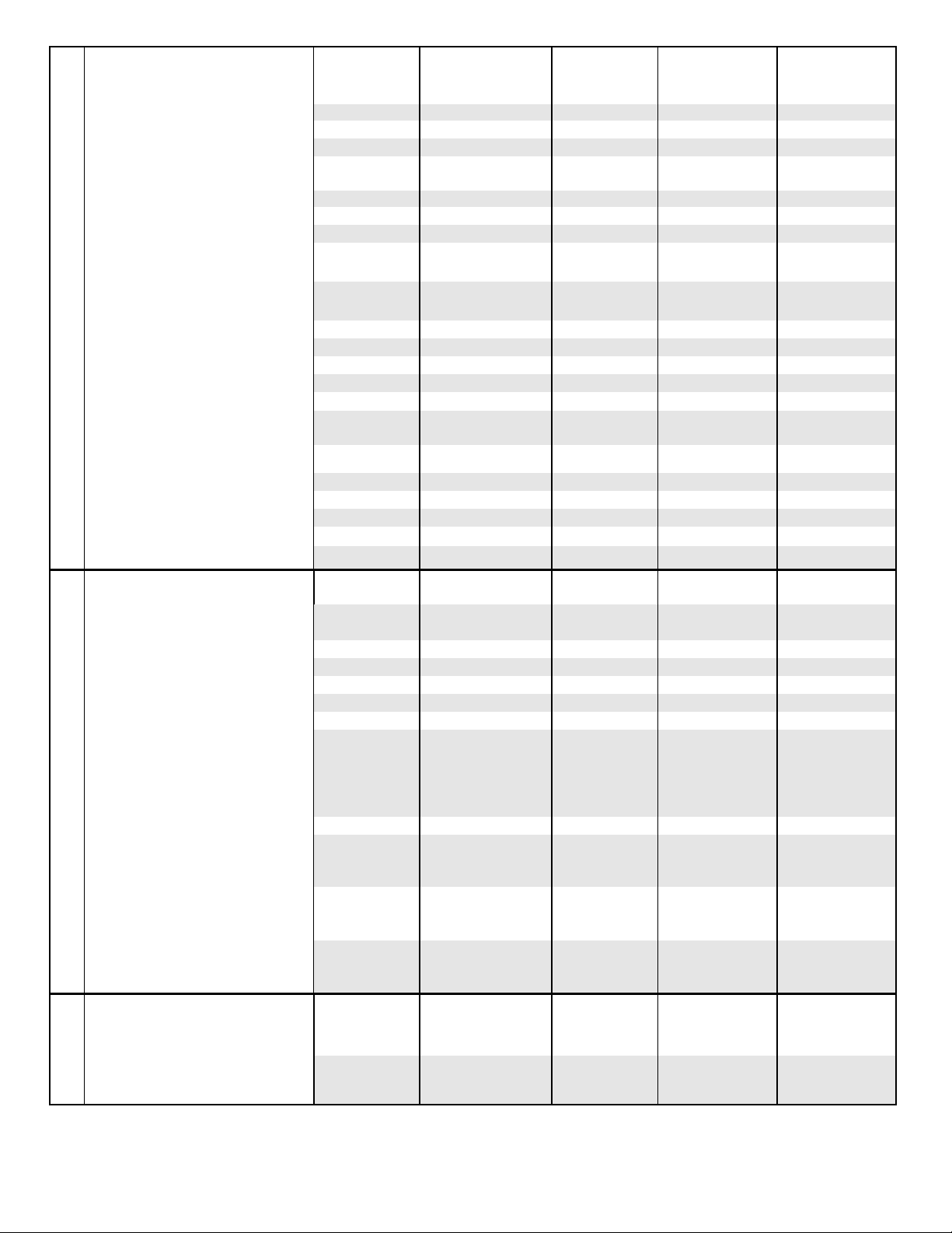
Features & Specifications
Model TS25 TS45 TS80 TS130 TS175
Standby output– 1500C Rise
G
G
E
(KVA/KW):
3 PH @ 480 Volt 25/20 48/38 81/65 134/107 175/140
3 PH @ 208/240 Volt 25/20 46/37 72/58 131/105 169/135
1 PH @ 240 Volt 18/18 27/27 45/45 70/70 80/80
Continuous Output–
1250C Rise (KVA/KW):
3 PH @ 480 Volt 23/18 44/35 75/60 121/97 169/135
3 PH @ 208/240 Volt 23/18 44/35 69/55 119/95 156/125
1 PH @ 240 Volt 18/18 25/25 43/43 66/66 75/75
Voltage – 3 PH Adjustable 208/220/240/
N
E
Voltage – 1 PH Adjustable 120/127/139/
R
A
T
O
R
E
N
G
I
N
E
Amperage (Continuous):
3 PH 480 Volt 27.1 52.6 90.2 145.8 203.0
3 PH 208 Volt 62.5 121.4 190.8 329.6 433.7
3 PH 240 Volt 54.1 105.3 165.4 285.7 375.9
1 PH 240 Volt/120 Volt 75.0/150.0 104.2/208.3 179.2/358.3 275/550 312.5/625.0
Receptacles:
120 Volt, 15 Amp GFCI 4 6 6 6 6
120/240 Volt, 50 Amp,
CS6369 Twistlock
Voltage Regulation 1/2% 1/2% 1/2% 1/2% 1/2% 1/2%
Power Factor – 3 Phase 0.8 0.8 0.8 .08 .08
Total Harmonic Distortion <5% <5% <5% <5% <5%
Engine Make/Model Isuzu
Fuel Consumption (GPH):
Approx. Run Time (Hrs.):
Battery Recommendation Min. Cold
(Battery not included)
Frequency 50 or 60 Hertz 50 or 60 Hertz 50 or 60 Hertz 50 or 60 Hertz 50 or 60 Hertz
Insulation Class F Class F Class F Class F Class F
Design Water Cooled
Starting System 12 VDC 12 VDC 12 VDC 12 VDC 12 VDC
Displacement (cid) 133.0 264.2 276.0 414.0 498.0
Cylinders 4 4 4 6 6
HP @ Rated Speed 34.5 64.0 100.0 166.0 211.0
RPM 1800 1800 1800 1800 1800
Safety Shutdowns:
High Temperature Std. Std. Std. Std. Std.
Low Oil Std. Std. Std. Std. Std.
Overspeed Std. Std. Std. Std. Std.
Overcrank Std. Std. Std. Std. Std.
Fuel Capacity 50 80 80 160 160
1/2 Load 1.3 2.0 2.7 4.2 5.6
Full Load 2.0 3.4 4.9 8.1 10.5
1/2 Load 38 40 30 38 29
Full Load 25 24 16 20 15
Cranking Amps
416/440/460/480
240/254/277
2 3 3 3 3
4LE
4 Cycle Diesel
750 900 900 (2) 750 (2) 750
208/220/240/
416/440/460/480
120/127/139/
240/254/277
Isuzu
4BG1
Water Cooled
4 Cycle Diesel
208/220/240/
416/440/460/480
120/127/139/
240/254/277
John Deere
TO4045T
Water Cooled
4 Cycle Diesel
208/220/240/
416/440/460/480
120/127/139/
240/254/277
John Deere
TO6068
Water Cooled
4 Cycle Diesel
208/220/240/
416/440/460/480
120/127/139/
240/254/277
John Deere
RG6081T
Water Cooled
4 Cycle Diesel
Dimensions (L x W x H):
With Trailer 123” x 62” x 70” 139” x 60” x 81” 139” x 60” x 81” 163” x 66” x 94” 163” x 66” x 94”
Without Trailer 74” x 38” x 52” 84” x 38” x 61” 84” x 38” x 61” 108” x 42” x 74” 108” x 42” x 74”
Weight (Lbs.):
Without Fuel 2265 3540 3848 5600 6200
Without Fuel & Trailer 1790 2829 3053 4610 5205
7
Page 11

8
Page 12
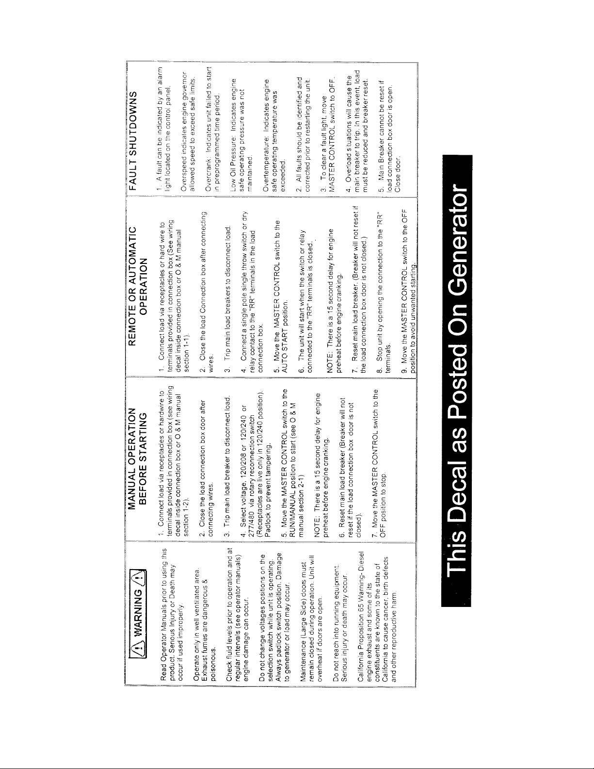
SWITCHABLE
ELECTRICAL CONNECTION INFORMATION
WARNING: High voltage may be present at receptacles and load studs while engine is
operating – DANGER of electrical shock is present. Use extreme care.
LOAD RECEPTACLES
1. Voltage is present in 120/240 volt switch position only.
2. Load wires may be brought into receptacle compartment through access door at control station.
HARD WIRE LOAD TERMINAL BLOCK
1. Voltage available at load block is outlined in chart below.
2. Cables must be brought into load block compartment through access hole in base of trailer.
3. Opening load block door will cause load disconnect to trip.
4. Do not start engine with load turned “on”. Allow engine to come up to speed and warm up (1).
5. If left unattended, lock all doors to prevent tampering or injury.
AVAILABLE VOLTAGE:
SWITCH POSITION
277/480 1–2–3 = 480 VAC, 3 Phase
1–N, 2–N, 3–N = 277 VAC, 1 Phase
120/240 1–2–3 = 240 VAC, 3 Phase
2–3 = 240 VAC, 1 Phase
2–N, 3–N = 120 VAC, 1 Phase
1–N = 180 – 200 VAC, Wild Leg
120/208 1–2–3 = 208 VAC, 3 Phase
2–3 = 208 VAC, 1 Phase
1–N, 2–N, 3–N = 120 VAC, 1 Phase
STUD
NOTE: To prevent damage to loads and generator, select voltage switch position prior to starting
engine.
NOTE: Upon switching voltage selector switch, adjust voltage and adjust rheostat (located on engine
control panel) for proper voltage.
Revised: October 3, 2002 D:\ISO9001\FORMS\MSW’98bbk
Effective: April 23, 1999
Form#: S–PSG–001–15
9
Page 13

CONNECTION INFORMATION
Your new Baldor Generator has all interconnecting wiring terminated at a junction box. All wiring will be
clearly labeled as being load; remote start contacts and AC input terminals and are to be connected as
described below.
Load – These connections are rated and sized according to the KW of the generator. Proper lead
wire from these points to the automatic transfer switch (or load switching device) is mandatory.
See enclosed transfer switch information for corresponding generator input terminals.
Remote Start Contacts – This two–wire connection, once connected to an appropriate switch,
will start the generator and perform as described in the remote start/stop literature. These
contacts are connected to the “Engine Start Contacts” of the automatic transfer switch.
A Two Pole normally open, closed to operate switch may also be used to start the generator.
AC Input – These connections are for units with float type battery chargers or engine block
heater combinations. A Constant supply of 120 volts AC (or as specified) is needed at these
terminals to power these devices.
NOTE: Power is not required when the unit is in operation. Internal battery charging and radiant heat
during operation eliminate the need for these devices.
NOTE: It is recommended that units utilizing an automatic transfer switch with adjustable time delays
have the initial adjustments made prior to start–up.
Factory recommendations are; allow a 2 second delay on start–up, 15–second delay on emergency to
normal.
Revised: March 20,2001 D:\ISO9001\FORMS\MSW’98bbk
Effective: April 23, 1999
Form#: S–PSG–001–19
10
Page 14

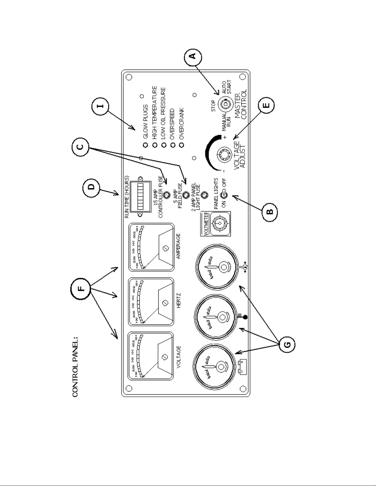
CONTROL PANEL OPERATION
AND FUNCTION
A. MASTER CONTROL SWITCH – This switch controls the starting and stopping of the engine via
the engine control logic circuitry.
With this switch in the “Manual” mode, the engine will start and run immediately after a
10 – 20 second time delay.
CAUTION: Please note that once the engine has been told to start, the gen set
should be treated as though it is operational, even though the start
delay has not yet allowed the engine to crank.
With this switch in the “Automatic” mode, the engine can be started and stopped from a remote
contact. (Standard switch, transfer switch, etc.) There is a time delay, to cool down, of 60–90
seconds when the unit is shut down from the remote contacts while the Master Control Switch is in
the “Automatic Mode.
With this switch in the “Off” position, the engine will immediately stop. The position must also be
utilized to clear fault shut–down conditions.
B. PANEL LIGHTS – By turning on the panel light switch, the panel lights will be energized and will
illuminate the control panel. The fuse next to the switch is to protect this circuit from damage due to
excessive current.
C. FIELD AND CONTROLLER FUSES – These fuses protect the internal workings of the generator
set.
D. GAUGES – These gauges monitor some of the more critical operating parameters of the engine as
well as the run time of the generator set.
The Voltmeter displays the charging rate that is currently being produced by the engine’s alternator to
facilitate the charging of the battery. This gauge should normally be above 12.5V whenever the unit is
running. If you ever notice the gauge is reading below 12V while the engine is running please contact
the service department at Baldor Generators.
The Temperature Gauge monitors and displays the operating temperature of the engines coolant. The
point at which a fault shut–down will occur is approximately 230°F.
The Oil Pressure Gauge displays and monitors the current operating pressure of the engine’s oil
system. The trip point at which a fault shutdown will occur is approximately 15 PSI or below.
Fuel level is checked by the owner or is usually a separately supplied fuel tank.
The Hour Meter accumulates and displays the total running time of the generator set.
11
Page 15

E. VOLTAGE ADJUST – The rheostat allows the user to “fine tune” the generator set’s voltage
output. It is normally used to adjust output voltage after switching the output of the generator set to a
different voltage.
F. METERS – These meters monitor and display the current operating parameters of the generator set.
The Voltmeter monitors and displays the current operating AC output of the generator set.
The Hertz Meter monitors and displays the current operating frequency of the generator set.
The ammeter monitors and displays the amount of current that is being delivered by the generator set.
This meter works in conjunction with the Voltmeter Switch (Item G) in determining which output leg
to monitor.
G. AMMETER SWITCH – The switch allows the user to switch between L1, L2 and L3 to monitor the
current in each output leg of the generator.
H. PANEL LIGHT – By turning on the panel light switch, the panel lights (Not pictured on diagram)
will be energized and will illuminate the control panel.
I – SYSTEM FAULT INDICATORS – These lights will come on when a fault condition or a warning
condition develops.
The “Low Oil Pressure” light will come on when the engine’s oil pressure drops below 15 PSI. This
condition will trigger a fault shut–down and the unit will stop.
The “Over–crank” light will come on when the engine has failed to start after four attempted crank
cycles. Each crank cycle consists of a 12 second time period followed by a 12 second rest time
period.
The “Over–speed” light will come on when the engine’s operating speed rises above it’s normal
operating parameters. This condition will trigger a fault shut–down and the engine will stop.
High Temperature light will come on when the engine’s operating temperature exceeds the safety
set–point.
12
Page 16
13
Page 17

OPERATION – PRE–START PROCEDURE
1. Fill system fuel tank with clean, fresh diesel fuel.
CAUTION: Wipe up any and all fuel spillage.
2. Fill engine crankcase to full mark with clean, fresh lubricating oil per attached engine operating guide.
3. Radiator coolant should be checked at the beginning of each day and filled in compliance with the engine
manufacturer’s guidelines.
4. Secure the generator for operation.
Skid mounted – the power generating system should be mounted to a smooth,
hard surface suitable for supporting the system under all stress conditions.
Trailer mounted – block wheels to prevent accidental movement.
Adequate clearance must be provided for access doors to fully open.
NOTE: The generating system exhaust also exits radiator end. When
positioning a generator system ensure position does not cause a
concentration of toxic emissions.
14
Page 18

OPERATION – STARTING
1. Conduct ‘Pre–start Procedures.
2. Switch the generator set to the applicable voltage setting.
3. Connect the load(s) to the circuit breaker.
WARNING: High voltage is present when the generator set is running.
4. Move the ‘Master Control Switch” to the appropriate position.
5. Adjust the voltage if necessary by turning the voltage adjustment knob located on the control panel.
15
Page 19

OPERATION
The prime mover utilized in this power generating system is controlled via an engine control module.
Starting is accomplished by commanding the control to ”start” the engine. This command can be
given by a number of controls.
? The operator control mounted on the front panel.
? The remote controls via the transfer switch or remote start terminal closure.
Initially, the system may be started and operated by placing the operator control in the ”manual/run”
position. To cease operation, return the switch to the ”off” position.
NOTE: Clear unit of all loose objects and perform all ”pre–start” procedures before operating
generator system.
ENGINE CONTROL MODULE:
The engine control module (ECM) is a microprocessor– based module that monitors the control and
safety inputs and provides all the required START and STOP functions automatically.
The following front panel controls and instruments are wired into the microprocessor through the
ECM terminal blocks:
1. Run–Off–Auto Switch
a. * ”Run” – run position causes the generator set to start and run immediately.
b. * ”Auto” – auto position allows unit to be controlled via any remote single–pole ”dry” contact
(transfer switch, etc.). Contact closure causes the unit to start and run, while contact opening causes
unit to shut down after a preset cool down period.
c. ”Off” – unit operation is terminated.
* – units equipped with Isuzu engines may have a time delay glow plug cycle before starting.
2. Lamp Test
Push button energizes all alarm lights simultaneously. This feature is disabled with the
run–stop–auto switch in the ”stop” position, and has no other effect on unit operation.
SAFETY INPUTS
1. Low Oil Pressure Shutdown – (LOP)
Monitoring of oil pressure begins for a preset time after unit starts and remains in effect until
unit is shut down (except as noted in ”loss of frequency input” below). The LOP signal is derived
from an oil pressure switch gauge mounted on the control panel
2. High Temperature Shutdown – (HT)
The engine temperature monitoring begins immediately with the start signal. However, if engine
temperature is excessive prior to start (i.e., heat soak after shutdown), the unit is permitted to
start.
The high temperature condition is permitted to exist for up to 60 seconds after the unit is running
before shutdown when alarm occurs. If the excessive temperature condition is corrected within
that time period, the HT circuit reverts to normal monitoring. The HT signal is derived from a
monitoring device located on the prime mover.
16
Page 20

3. Over–speed Adjustment – (OS) – Over Frequency
Over–speed protection is provided by a frequency sensing network within the controller. The trip
point of the frequency network is adjustable via a rheostat located on the top of the controller at
the right hand side. Clockwise (CW) rotation increases the trip frequency and, thereby, raises the
shutdown speed.
CRANKING CONTROL
1. Over–crank Protection
This feature provides a preset second crank cycle. Failure of the engine to start by the end of the
crank period results in an ”Over–crank” shutdown and alarm indication.
2. Cranking Disconnect Adjustment (CDS Adjustment)
The cranking disconnect signal is obtained by a frequency network within the controller. The trip
point of the frequency network is not adjustable.
LOSS OF FREQUENCY
Internal protection against loss of frequency input to the cranking disconnect circuit is programmed in
after the unit has started normally. In the event the frequency goes to zero (engine runs out of fuel,
frequency signal source fails, etc.) the LOP shutdown circuit is bypassed and a 12–second wait
period is initiated. If frequency returns within this time period, LOP monitoring resumes and operation
continues normally. If frequency has not returned at the end of this time period, the engine oil
pressure status is observed to determine whether the engine is actually running or stopped. If the
engine has stopped (i.e., air in fuel, etc.), the cranking cycle will begin in an effort to restart the
engine. If the engine has not stopped (loss of input signal, etc.), the unit is shutdown with an
”Over–crank” indication and alarm.
WARNING: Over–crank indication can mean a loss of crank–disconnect signal during the
previous run period. Attempting to restart the engine with no crank–disconnect signal can
destroy the starter motor, which can cause serious personal injury.
This is of particular note since the tendency is to pursue only cranking and start related faults. The
cranking disconnect signal source is a key component in this system and must be checked out
thoroughly whenever an ”Over–crank” shutdown occurs.
NOTE: The controller does not provide protection against loss of signal during start–up. A
shutdown with alarm, due to any of the above conditions, will prevent any subsequent
operation of the generator set. The run–stop–auto selector switch on the control panel
must be momentarily placed in the stop position to reset these functions.
CAUTION: If a dead battery is suspected, remove controller fuse, charge battery (or replace), and
then attempting starting. Damage to engine control may result from jump starting.
17
Page 21

TROUBLESHOOTING – GENERATOR
As with any machine, trouble may develop in electrical generators. It may be due to long service
or neglect of regular maintenance. Servicing, and checking. Should trouble develop, the following instructions will be helpful in tracing the cause and making repairs.
SPEED DEVIATIONS:
The generator speed should be maintained at rated nameplate speed. The frequency and volt-
age of the generator output depends on speed. If the generator runs slower than rated speed,
the voltage will drop off.
NO VOLTAGE
CAUSE
Loss of residual magnetism in Flash Field.
exciter field poles.
Open in stator windings Check for continuity in windings. Return to factory
Open or short in rotating rectifiers. Check rectifiers.
Short Circuited. Clear lead to restore voltage build–up.
Open in alternator field Check for continuity and return rotor to factory for
Shorted exciter armature Check for short and replace if faulty.
Shorted leads between exciter Test and repair
armature and generator field.
LOW VOLTAGE
CAUSE
CHECK AND REMEDY
for repair if open
repair if field coils are open.
CHECK AND REMEDY
Excessive load. Reduce load. With 3 phase generators, the load on
each leg should be as evenly balanced as possible
and should not exceed the rated current on any leg.
Low Speed. Check engine for malfunction or system for over-
load.
Line loss. Increase size of line lead wire.
18
Page 22

LOW VOLTAGE (Continued)
CAUSE
CHECK AND REMEDY
High resistance connections– Make better connection electrically and
Connections will be warm or hot mechanically.
Shorted field. Test field coils for possible short by checking resist-
ance with an ohmmeter or resistance bridge. Return rotor assembly to factory for repair if alternator
field coils are shorted.
Low power factor Reduce inductive (motor) load. Some AC motors
Draw approximately the same current regardless of
load. Do not use motors of larger horsepower rating
than is necessary to carry the mechanical load.
FLUCTUATING VOLTAGE
(May be indicated by flickering lights.)
CAUSE
CHECK AND REMEDY
Irregular speed of engine. Check engine for malfunction or load for fluctuation.
Fluctuating speed. Stabilize load. The addition of a lamp load (resist-
ance load) may compensate partially for load
changes caused by intermittent motor operation.
Do not overload.
Loose terminal or load connections. Make better connection mechanically and electri-
cally.
Defective bearing causing uneven air gap. Replace worn bearing.
HIGH VOLTAGE
CAUSE
CHECK AND REMEDY
Excessive speed. Check engine for malfunction.
OVERHEATING
CAUSE
CHECK AND REMEDY
Generator overloaded. Reduce load. (Check with ammeter and compare
with nameplate rating.)
Clogged ventilating screens. Clean air passages.
19
Page 23

OVERHEATING (continued)
CAUSE
CHECK AND REMEDY
High room temperature. Improve ventilation.
Insufficient circulation. Provide cross–ventilation.
Low power factory. Reduce inductive loads or install power factor im-
provement capacitors.
Unbalanced load The load on each leg should be as evenly balanced
as possible and should not exceed the rated cur-
rent on any leg.
Dry bearing. Replace bearing.
MECHANICAL NOISE
CAUSE
CHECK AND REMEDY
Defective bearing. Replace bearing.
Rotor scrubbing on stator. Bad bearing; replace. Bent shaft, return to factory.
Loosen end bell, tighten; loose drive discs, tighten.
Loose laminations. Return to factory.
Loose or misaligned coupling. Tighten or align.
GENERATOR FRAME PRODUCES SHOCK WHEN TOUCHED
CAUSE
CHECK AND REMEDY
Static charge. Ground generator frame.
Grounded armature or field coil. Return to factory for repair.
20
Page 24

TROUBLESHOOTING – ENGINE
CODE LIST OF POSSIBLE CAUSES
1. Battery capacity low. 33. Piston rings not free or are worn or broken.
2. Bad electrical connections. 34. Valve stems and/or guide worn.
3. Fault in starter motor. 35.West type air cleaner too full or wrong oil used.
4. Fault in starter motor. 36. Crankshaft bearings worn or damaged..
5. Wrong grade of lubricating oil. 37. Not enough lubricating oil in the pump.
6. Low engine speed from starter motor. 38. Gauge not correct.
7. Stop control fault. 39. Lubricating oil pump worn.
8. Restriction in fuel lift pipe. 40. Relief valve not free to close.
9. Fault in fuel lift pump. 41. Relief valve not free to open.
10. Dirty fuel filter element. 42. Relief valve spring broken.
11. Restriction in air filter or induction system. 43. Fault in suction pipe of lubricating oil pump.
12. Air in fuel system. 44. Dirty lubricating oil filter element.
13. Fault in fuel injection pump. 45. Piston damaged.
14. Fault in atomizers or not correct type. 46. Piston height not correct.
15. Cold start equipment not used correctly. 47. Fan damaged.
16. Fault in cold start equipment. 48. Fault in engine mounting (housing).
17. Broken fuel injection pump drive. 49. Flywheel housing or flywheel not aligned
18. Fuel injection pump timing not correct. correctly.
19. Valve timing not correct. 50. Fault in thermostat or wrong type.
20. Bad compression. 51. Restriction in coolant passages.
21. restriction in fuel tank vent. 52. Water pump drive belt loose.
22. Type or grade of fuel not correct. 53. Restriction in radiator.
23. Restriction of engine speed control movement. 54. Fault in water pump.
24. Restriction in exhaust pipe. 55. Restriction in breather pipe.
25. Cylinder head gasket leaks. 56. Damaged valve stem oil seals (where used).
26. Engine temperature too high. 57. Not enough coolant in system.
27. Engine temperature too low. 58. Restriction in sump strainer.
28. Valve tip clearances not correct. 59. Valve spring broken.
29. Valves not free. 60. Fault in exhaust or vacuum pipe leakage.
30. Wrong high pressure pipes. 61. Turbo charger impeller damage, or dirty impeller.
31. Worn cylinder bores. 62. Turbo charger lubricating oil seal leaks.
32. Valves and seats do not seal correctly. 63. Induction system leaks (turbo charged engines.)
21
Page 25

22
Page 26

MMAAGGNNAAPPLLUUSS GGEENNEERRAATTOOR
R
228800 ---- 443300 FFrraamme
IInnssttaallllaattiioonn,, OOppeerraattiioonn aanndd MMaaiinntteennaanncce
MMaannuuaal
l
e
e
MMaarraatthhoonn EElleeccttrriic
AA SSuubbssiiddiiaarryy ooff RReeggaall--BBeellooiitt CCoorrpp.
110000 EEaasstt RRaannddoollpphh SSttrreeeet
PP..OO.. BBooxx 8800003
WWaauussaauu,, WWII 5544440022--8800003
PPhhoonnee:: ((771155)) 667755 3333111
FFaaxx:: ((771155)) 667755 6633661
c
t
3
3
1
1
.
Page 27

TTAABBLLEE OOFF CCOONNTTEENNTTS
S
SSAAFFEETTY
RREECCEEIIVVIINNGG AANNDD SSTTOORRAAGGE
PPRRIINNCCIIPPLLEESS OOFF OOPPEERRAATTIIOON
IINNSSTTAALLLLAATTIIOON
Y..............................................................................................................................................................................................44
E.........................................................................................................................................................44
UUNNPPAACCKKIINNGG AANNDD HHAANNDDLLIINNG
SSTTOORRAAGGE
E........................................................................................................................................................................................44
G...................................................................................................................................................44
N ......................................................................................................................................................55
A
M
AAGGNNA
FFIIGGUURREE 11 ---- M
FFIIGGUURREE 22 ---- T
V
OOLLTTAAGGEE
V
T
R
EEGGUULLAATTIIOON
R
MMOOTTOORR SSTTAARRTTIINNG
PPLLUUSS C
YYPPIICCAALL
M
AAGGNNA
M
N
.....................................................................................................................................................................66
G.......................................................................................................................................................................66
PPAARRAALLLLEELL OOPPEERRAATTIIOON
NNOONNLLIINNEEAARR LLOOAADDIINNG
G................................................................................................................................................................66
C
N ..............................................................................................................................................................66
IIRRCCUUIITT
A
PPLLUUSS L
D
IIAAGGRRAAM
D
L
AAYYOOUUTT
N................................................................................................................................................................................66
PPRREEPPAARRAATTIIOONN FFOORR UUSSE
GGEENNEERRAATTOORR MMOOUUNNTTIINNG
SSiinnggllee BBeeaarriinngg UUnniittss.
E .............................................................................................................................................................66
G...........................................................................................................................................................77
. ...................................................................................................................................................................77
TTwwoo BBeeaarriinngg GGeenneerraattoorrss ---- DDiirreecctt DDrriivve
TTwwoo BBeeaarriinngg UUnniittss ---- BBeelltt DDrriivveen
EENNDD PPLLAAYY TTEESSTTIINNG
TTOORRSSIIOONNAALL VVIIBBRRAATTIIOON
G.....................................................................................................................................................................77
N.............................................................................................................................................................77
n.................................................................................................................................................77
EENNVVIIRROONNMMEENNTTAALL CCOONNSSIIDDEERRAATTIIOONNS
M
...............................................................................................................................55
D
D
IIAAGGRRAAM
M
.................................................................................................................55
e .....................................................................................................................................77
S.....................................................................................................................................88
WWIIRRIINNGG CCOONNNNEECCTTIIOONNS
OOPPEERRAATTIIOON
N....................................................................................................................................................................................1111
PPRREE--SSTTAARRTT IINNSSPPEECCTTIIOON
SSTTAARRTT--UUP
P.....................................................................................................................................................................................1111
SSHHUUTTDDOOWWNN PPRROOCCEEDDUURRE
MMAAIINNTTEENNAANNCCE
E .............................................................................................................................................................................1122
DDRRYYIINNGG WWIINNDDIINNGGS
SSppaaccee HHeeaatteerrs
FFoorrcceedd AAiir
TTEESSTTIINNG
G..........................................................................................................................................................................................1133
V
V
C
C
C
C
I
I
I
IISSUUAALL
I
OONNSSTTAANNTT
OONNTTIINNUUIITTYY
NNSSUULLAATTIIOONN
DDIIOODDEE TTEESSTTIINNG
SSEERRVVIICCE
E..........................................................................................................................................................................................1144
GGEENNEERRAAL
s.............................................................................................................................................................................1133
r ..................................................................................................................................................................................1133
NNSSPPEECCTTIIOON
E
XXCCIITTAATTIIOONN
E
R
EESSIISSTTAANNCCEE
// R
T
............................................................................................................................................................................1144
T
EESST
T
G..........................................................................................................................................................................1144
L .....................................................................................................................................................................................1144
FFIIEELLDD FFLLAASSHHIINNG
B
EEAARRIINNGG
B
R
EEMMOOVVAAL
R
S................................................................................................................................................................88
N ..........................................................................................................................................................1111
E.........................................................................................................................................................1122
S ...................................................................................................................................................................1133
N
........................................................................................................................................................................1133
T
.........................................................................................................................................................1133
T
EESST
T
T
.....................................................................................................................................................1133
T
EESST
T
G........................................................................................................................................................................1144
L
........................................................................................................................................................................1155
OOppppoossiittee DDrriivvee EEnndd BBeeaarriinngg BBrraacckkeett RReemmoovvaall.
DDrriivvee EEnndd BBeeaarriinngg BBrraacckkeett RReemmoovvaall,
TTwwoo BBeeaarriinngg UUnniittss.
BBEEAARRIINNGG RREEPPLLAACCEEMMEENNT
R
EECCTTIIFFIIEERR
R
D
IIOODDEE
D
A
SSSSEEMMBBLLYY
A
R
EEPPLLAACCEEMMEENNT
R
......................................................................................................................................................................1155
T ........................................................................................................................................................1155
R
R
T
.....................................................................................................................................................................1155
EEMMOOVVAAL
L
....................................................................................................................................................1155
..........................................................................................................................1155
, ........................................................................................................................................1155
2
2
Page 28

RREETTUURRNNEEDD GGOOOODDS
S ......................................................................................................................................................................1166
TTRROOUUBBLLEESSHHOOOOTTIINNG
GGEENNEERRAATTOORR PPRROODDUUCCEESS NNOO VVOOLLTTAAGGE
GGEENNEERRAATTOORR PPRROODDUUCCEESS LLOOWW VVOOLLTTAAGGEE,, NNOO LLOOAAD
GGEENNEERRAATTOORR PPRROODDUUCCEESS LLOOWW VVOOLLTTAAGGEE WWHHEENN LLOOAADD AAPPPPLLIIEED
GGEENNEERRAATTOORR PPRROODDUUCCEESS FFLLUUCCTTUUAATTIINNGG VVOOLLTTAAGGE
GGEENNEERRAATTOORR PPRROODDUUCCEESS HHIIGGHH VVOOLLTTAAGGE
GGEENNEERRAATTOORR BBUUIILLDDSS VVOOLLTTAAGGEE FFRROOMM SSTTAARRTTUUPP,, TTHHEENN GGOOEESS TTOO LLOOWW ((RREESSIIDDUUAALL)) VVOOLLTTAAGGE
GGEENNEERRAATTOORR IISS OOVVEERRHHEEAATTIINNG
GGEENNEERRAATTOORR PPRROODDUUCCEESS MMEECCHHAANNIICCAALL NNOOIISSE
EEQQUUIIPPMMEENNTT RRUUNNSS NNOORRMMAALLLLYY OONN UUTTIILLIITTYY PPOOWWEERR,, BBUUTT WWIILLLL NNOOTT RRUUNN OONN GGEENNEERRAATTOOR
SSPPEECCIIFFIICCAATTIIOONNS
PPAARRTTSS LLIISSTT –– SSIINNGGLLEE BBEEAARRIINNG
TTyyppiiccaall GGeenneerraattoorr CCrroossss SSeeccttiioon
PPAARRTTSS LLIISSTT –– DDUUAALL BBEEAARRIINNG
TTyyppiiccaall GGeenneerraattoorr CCrroossss SSeeccttiioon
G...................................................................................................................................................................1166
E................................................................................................................................1177
D.........................................................................................................1177
D ..................................................................................1188
E..........................................................................................................1188
E............................................................................................................................1188
G..............................................................................................................................................1199
E ..................................................................................................................1199
S..........................................................................................................................................................................2200
G...............................................................................................................................................2211
n ...............................................................................................................................................2211
G..................................................................................................................................................2222
n ...............................................................................................................................................2222
E...........................1199
R.................................1199
3
3
Page 29

SSAAFFEETTY
Y
WWhheenn iinn ddoouubbtt,, aasskk.. QQuueessttiioonnss aarree mmuucchh eeaassiieerr ttoo hhaannddlle
tthhaann mmiissttaakkeess ccaauusseedd bbyy aa mmiissuunnddeerrssttaannddiinngg ooff tthhe
iinnffoorrmmaattiioonn pprreesseenntteedd iinn tthhiiss mmaannuuaall.
.
e
e
PPLLEEAASSEE RREEMMEEMMBBEERR SSAAFFEETTYY FFIIRRSSTT..
ooff tthhee iinnssttrruuccttiioonnss oorr pprroocceedduurreess ccoonnttaaiinneedd hheerreeiinn,, sseeeek
qquuaalliiffiieedd hheellpp bbeeffoorree ccoonnttiinnuuiinngg.
TThhiiss sseerrvviiccee mmaannuuaall eemmpphhaassiizzeess tthhee ssaaffeettyy pprreeccaauuttiioonns
nneecceessssaarryy dduurriinngg tthhee iinnssttaallllaattiioonn,, ooppeerraattiioonn,, aannd
mmaaiinntteennaannccee ooff yyoouurr MMaaggnnaaPPLLUUSS ggeenneerraattoorr.. EEaacchh sseeccttiioon
ooff tthhiiss mmaannuuaall hhaass ccaauuttiioonn aanndd wwaarrnniinngg mmeessssaaggeess.. TThheesse
mmeessssaaggeess aarree ffoorr yyoouurr ssaaffeettyy,, aanndd tthhee ssaaffeettyy ooff tthhe
eeqquuiippmmeenntt iinnvvoollvveedd.. IIff aannyy ooff tthheessee ccaauuttiioonnss oorr wwaarrnniinnggss iis
nnoott rreeaaddiillyy uunnddeerrssttoooodd,, sseeeekk ccllaarriiffiiccaattiioonn ffrroomm qquuaalliiffiieed
ppeerrssoonnnneell bbeeffoorree pprroocceeeeddiinngg.
BBeeffoorree aannyy sseerrvviiccee wwoorrkk iiss ddoonnee,, ddiissccoonnnneecctt aallll ppoowweer
ssoouurrcceess aanndd lloocckk oouutt aallll ccoonnttrroollss ttoo pprreevveenntt aann uunneexxppeecctteed
ssttaarrtt--uupp ooff tthhee ggeenneerraattoorr sseett ddrriivveerr.. PPrrooppeerr ggrroouunnddiinng
((eeaarrtthhiinngg)) ooff tthhee ggeenneerraattoorr ffrraammee aanndd ddiissttrriibbuuttiioonn ssyysstteemm iin
ccoommpplliiaannccee wwiitthh llooccaall aanndd nnaattiioonnaall eelleeccttrriiccaall ccooddeess aannd
ssppeecciiffiicc ssiittee rreeqquuiirreemmeennttss mmuusstt bbee pprroovviiddeedd.. TThheessee ssaaffeetty
pprreeccaauuttiioonnss aarree nneecceessssaarryy ttoo pprreevveenntt ppootteennttiiaall sseerriioouus
ppeerrssoonnaall iinnjjuurryy,, oorr eevveenn ddeeaatthh.
TThhee hhaazzaarrddss aassssoocciiaatteedd wwiitthh lliiffttiinngg oorr mmoovviinngg yyoouur
MMaaggnnaaPPLLUUSS ggeenneerraattoorr aarree ppooiinntteedd oouutt iinn tthhee iinnssttaallllaattiioonn aannd
mmaaiinntteennaannccee sseeccttiioonnss.. IInnccoorrrreecctt lliiffttiinngg oorr mmoovviinngg ccaann rreessuullt
iinn ppeerrssoonnaall iinnjjuurryy oorr ddaammaaggee ttoo tthhee uunniitt.
PPrriioorr ttoo ssttaarrtt--uupp ooff tthhee uunniitt eennssuurree tthhaatt aallll ggeenneerraattoorr lleeaadds
aarree pprrooppeerrllyy ccoonnnneecctteedd ttoo tthhee ggeenneerraattoorr lliinnkk bbooaarrdd llooccaatteed
iinnssiiddee tthhee ccoonnnneeccttiioonn bbooxx.. AAllwwaayyss aassssuummee tthhaatt tthheerree wwiillll bbe
vvoollttaaggee pprreesseenntt aatt tthhee ggeenneerraattoorr tteerrmmiinnaallss wwhheenneevveerr tthhe
ggeenneerraattoorr''ss sshhaafftt iiss rroottaattiinng
RReessiidduuaall vvoollttaaggee iiss pprreesseenntt aatt tthhee ggeenneerraattoorr tteerrmmiinnaallss aanndd aat
tthhee aauuttoommaattiicc vvoollttaaggee rreegguullaattoorr ppaanneell ccoonnnneeccttiioonnss eevveenn wwiitth
tthhee rreegguullaattoorr ffuussee rreemmoovveedd.. CCaauuttiioonn mmuusstt bbee eexxeerrcciisseedd,, oor
sseerriioouuss iinnjjuurryy oorr ddeeaatthh ccaann rreessuulltt.
.
.
.
,
g
,
aanndd pprroocceeeedd aaccccoorrddiinnggllyy.
.
IIff yyoouu aarree nnoott ssuurre
.
e
k
s
d
n
e
e
s
d
r
d
g
n
d
y
s
r
d
t
s
d
e
e
.
t
h
r
RREECCEEIIVVIINNGG AANNDD SSTTOORRAAGGE
RREECCEEIIVVIINNGG AANNDD SSTTOORRAAGGE
UUppoonn rreecceeiipptt ooff tthhee ggeenneerraattoorr,, iitt iiss rreeccoommmmeennddeedd tthhaatt iitt bbe
ccaarreeffuullllyy eexxaammiinneedd ffoorr ppoossssiibbllee sshhiippppiinngg ddaammaaggee.. TThhe
ggeenneerraattoorr wwaass ggiivveenn ttoo tthhee ffrreeiigghhtt ccaarrrriieerr iinn ggoooodd ccoonnddiittiioonn;
tthhuuss,, tthhee ccaarrrriieerr iiss rreessppoonnssiibbllee ffoorr tthhee pprroodduucctt ffrroomm tthhe
ffaaccttoorryy ddoocckk ttoo tthhee ddeessttiinnaattiioonn.. AAnnyy ddaammaaggee sshhoouulldd bbe
nnootteedd oonn tthhee ffrreeiigghhtt bbiillll bbeeffoorree aacccceeppttiinngg tthhee sshhiippmmeenntt.. AAnny
ccllaaiimmss ffoorr ddaammaaggee mmuusstt bbee pprroommppttllyy ffiilleedd wwiitthh tthhee ddeelliivveerriinng
.
ccaarrrriieerr.
UUNNPPAACCKKIINNGG AANNDD HHAANNDDLLIINNG
CCaarreeffuullllyy rreeaadd aallll iinnssttrruuccttiioonn ttaaggss sshhiippppeedd wwiitthh tthhee uunniitt.
WWhheenn lliiffttiinngg,, aattttaacchh aann oovveerrhheeaadd ccrraannee ttoo tthhee lliiffttiinngg lluugg((ss)) oon
tthhee ggeenneerraattoorr ffrraammee.. AAppppllyy lliiffttiinngg ffoorrcceess iinn aa vveerrttiiccaal
ddiirreeccttiioonn.. WWhheenn ttrraannssppoorrttiinngg ssiinnggllee bbeeaarriinngg ggeenneerraattoorrss,, tthhe
ggeenneerraattoorr’’ss rroottoorr mmuusstt bbee aaddeeqquuaatteellyy ssuuppppoorrtteedd ttoo pprreevveennt
ddaammaaggee.
.
E
TTHHE
LLIIFFTTIINNG
NNOOT
R
TTHHE
E
D
T
LLIIFFT
AASSSSEEMMBBLLY
GGEENNEERRAATTOORR.. PPEERRSSOONNAAL
DDEESSIIGGNNEED
O
DDO
DDRRIIVVEER
N
OON
EEQQUUIIPPMMEENNT
G
LLUUGG ((SS)
O
TTO
SSUUPPPPOORRT
T
T
DDAAMMAAGGE
WWAARRNNIINNG
)
A
A
CCOOMMPPLLEETTE
Y
Y
BBY
E
MMAAY
N
OON
TTHHE
T
TTHHE
MMEEAANNS
Y
RREESSUULLTT.
G
E
E
E
S
E
E
G
GGEENNEERRAATTOOR
GGEENNEERRAATTOOR
GGEENNEERRAATTOOR
OOF
F
LLIIFFTTIINNG
L
IINNJJUURRY
.
G
R
AARRE
R
OONNLLYY.
R
AANND
LLUUGG ((SS)
Y
OOR
e
e
;
e
e
y
g
.
n
l
e
t
E
.
D
)
R
TThhiiss mmaannuuaall iiss nnoott iinntteennddeedd ttoo bbee aa ssuubbssttiittuuttee ffoorr pprrooppeerrlly
ttrraaiinneedd ppeerrssoonnnneell.. IInnssttaallllaattiioonn aanndd rreeppaaiirrss sshhoouulldd oonnllyy bbe
aatttteemmpptteedd bbyy qquuaalliiffiieedd,, ttrraaiinneedd ppeeooppllee.. TThhee ccaauuttiioonnss aannd
wwaarrnniinnggss ppooiinntt oouutt kknnoowwnn ccoonnddiittiioonnss aanndd ssiittuuaattiioonnss tthhaatt aarre
ppootteennttiiaallllyy hhaazzaarrddoouuss.. EEaacchh iinnssttaallllaattiioonn mmaayy wweellll ccrreeaattee iitts
oowwnn sseett ooff hhaazzaarrdds
s
y
e
d
e
s
SSTTOORRAAGGE
IInn tthhee eevveenntt tthhaatt tthhee ggeenneerraattoorr iiss nnoott iimmmmeeddiiaatteellyy iinnssttaalllleed
oonn iittss pprriimmee mmoovveerr,, iitt iiss rreeccoommmmeennddeedd tthhaatt tthhee uunniitt bbee ssttoorreed
iinnddoooorrss iinn aa cclleeaann,, ddrryy aarreeaa,, wwhhiicchh iiss nnoott ssuubbjjeecctt ttoo rraappiid
cchhaannggeess iinn tteemmppeerraattuurree aanndd hhuummiiddiittyy.. IIff tthhee ggeenneerraattoorr iis
ssttoorreedd ffoorr aa lloonngg ppeerriioodd ooff ttiimmee,, tthhee ggeenneerraattoorr sshhoouulldd bbe
tteesstteedd,, cclleeaanneedd aanndd ddrriieedd aass rreeqquuiirreedd bbeeffoorree bbeeiinngg ppuutt iinntto
sseerrvviiccee.. SSeeee tthhee mmaaiinntteennaannccee sseeccttiioonn ooff tthhiiss mmaannuuaall ffoor
ffuurrtthheerr iinnffoorrmmaattiioonn.. IIff tthhee uunniitt hhaass bbeeeenn ssttoorreedd iinn aann aarreea
wwhheerree iitt hhaass bbeeeenn ssuubbjjeecctt ttoo vviibbrraattiioonn,, iitt iiss rreeccoommmmeennddeed
tthhaatt tthhee bbeeaarriinngg((ss)) bbee iinnssppeecctteedd aanndd rreeppllaacceedd aass nneecceessssaarryy.
4
4
E
d
d
d
s
e
o
r
a
d
.
Page 30

PPRRIINNCCIIPPLLEESS OOFF OOPPEERRAATTIIOON
N
PMG (optional)
PMG Field
(rotor)
N
S
PMG
Armature
(stator)
PMG Input Power (optional)
(1 phase, 300/250 hertz)
Exciter Field
(stator)
(+)
DC
(in)
(-)
Exciter Armature
3 Phase AC (out)
Exciter Field Power
(DC out)
FFIIGGUURREE 11 ---- MMaaggnnaaPPLLUUSS CCiirrccuuiitt DDiiaaggrraam
Rotating Assembly
(rotor)
m
Rotating Rectifier Assembly
3 Phase -- Full Bridge
Automatic
Voltage
Regulator
Main Field
(rotor)
(+)
DC
(in)
(-)
Input Power -- Single Phase
(shunt powered regulator)
Sensing Input -- Single Phase
3 phase (optional)
Main Armature
3 Phase AC (out)
(stator)
L
1
L
2
L
3
FFIIGGUURREE 22 ---- TTyyppiiccaall MMaaggnnaaPPLLUUSS LLaayyoouutt DDiiaaggrraam
m
5
5
Page 31

PPRRIINNCCIIPPLLEE OOFF OOPPEERRAATTIIOON
MMaaggnnaaPPLLUUSS ggeenneerraattoorrss aarree aa bbrruusshhlleessss,, sseellff eexxcciitteedd,, aannd
eexxtteerrnnaallllyy vvoollttaaggee rreegguullaatteedd,, ssyynncchhrroonnoouuss AACC ggeenneerraattoorr.
TThhee ggeenneerraattoorr iiss mmaaddee uupp ooff ssiixx mmaajjoorr ccoommppoonneennttss:: mmaaiin
ssttaattoorr ((aarrmmaattuurree)),, mmaaiinn rroottoorr ((ffiieelldd)),, eexxcciitteerr ssttaattoorr ((ffiieelldd)),
eexxcciitteerr rroottoorr ((aarrmmaattuurree)),, rreeccttiiffiieerr aasssseemmbbllyy,, aanndd vvoollttaagge
rreegguullaattoorr.. IInn uunnddeerrssttaannddiinngg tthhee aabboovvee tteerrmmiinnoollooggyy,, nnoottee tthhe
ffoolllloowwiinngg:: ssttaattoorrss aarree ssttaattiioonnaarryy,, rroottoorrss rroottaattee,, aa ffiieelldd iiss aan
eelleeccttrriiccaall iinnppuutt,, aanndd aann aarrmmaattuurree iiss aann eelleeccttrriiccaall oouuttppuutt.
TThheessee ssyysstteemm ccoommppoonneennttss aarree eelleeccttrriiccaallllyy iinntteerrccoonnnneecctteedd aas
sshhoowwnn iinn ffiigguurree 11 aanndd pphhyyssiiccaallllyy llooccaatteedd aass sshhoowwnn iin
.
ffiigguurree 22.
N
ggeenneerraattoorrss ggeenneerraallllyy ssuuppppllyy ..33 ttoo ..44 hhoorrsseeppoowweerr ppeer
ggeenneerraattoorr kkWW iinn mmoottoorr ssttaarrttiinngg ccaappaabbiilliittyy.. FFoorr ssppeecciiffiicc ddaatta
ccoonnttaacctt MMaarraatthhoonn EElleeccttrriicc.
d
.
n
,
e
e
n
.
s
n
PPAARRAALLLLEELL OOPPEERRAATTIIOON
AAllll MMaaggnnaaPPlluuss ggeenneerraattoorrss aarree bbuuiilltt wwiitthh 22//33 ppiittcchh mmaaiinn ssttaattoor
wwiinnddiinnggss aanndd ffuullll aammoorrttiisssseeuurr ((ddaammppeerr)) wwiinnddiinnggss.. TThheesse
ffeeaattuurreess mmaakkee tthhee MMaaggnnaaPPlluuss ggeenneerraattoorrss ssuuiittaabbllee ffoorr ppaarraalllleel
ooppeerraattiioonn wwhheenn eeqquuiippppeedd wwiitthh tthhee pprrooppeerr vvoollttaaggee rreegguullaattoorrs
aanndd vvoollttaaggee rreegguullaattoorr aacccceessssoorriieess.. CCoonnssuulltt wwiitthh tthhee ffaaccttoorry
ffoorr ffuurrtthheerr iinnffoorrmmaattiioonn rreellaattiivvee ttoo ppaarraalllleell ooppeerraattiioonnss.
.
N
.
r
a
r
e
l
s
y
TThhee ggeenneerraattoorr’’ss eexxcciitteerr ccoonnssiissttss ooff aa ssttaattiioonnaarryy ffiieelldd aanndd a
rroottaattiinngg aarrmmaattuurree.. TThhee ssttaattiioonnaarryy ffiieelldd ((eexxcciitteerr ssttaattoorr)) iis
ddeessiiggnneedd ttoo bbee tthhee pprriimmaarryy ssoouurrccee ooff tthhee ggeenneerraattoorr’’ss rreessiidduuaal
mmaaggnneettiissmm.. TThhiiss rreessiidduuaall mmaaggnneettiissmm aalllloowwss tthhee eexxcciitteerr rroottoor
((aarrmmaattuurree)) ttoo pprroodduuccee AACC vvoollttaaggee eevveenn wwhheenn tthhee eexxcciitteer
ssttaattoorr ((ffiieelldd)) iiss nnoott ppoowweerreedd.. TThhiiss AACC vvoollttaaggee iiss rreeccttiiffiieedd tto
DDCC bbyy tthhee rroottaattiinngg rreeccttiiffiieerr aasssseemmbbllyy aanndd ffeedd ddiirreeccttllyy ttoo tthhe
mmaaiinn rroottoorr ((ffiieelldd)).. AAss tthhee ggeenneerraattoorr sshhaafftt ccoonnttiinnuueess ttoo rroottaattee,
tthhee mmaaiinn rroottoorr ((ffiieelldd)) iinndduucceess aa vvoollttaaggee iinnttoo tthhee ggeenneerraattoorr''s
mmaaiinn ssttaattoorr ((aarrmmaattuurree)).. AAtt rraatteedd ssppeeeedd,, tthhee mmaaiinn ssttaattoorr’’s
vvoollttaaggee pprroodduucceedd bbyy tthhee rreessiidduuaall mmaaggnneettiissmm ooff tthhee eexxcciitteer
aalllloowwss tthhee aauuttoommaattiicc vvoollttaaggee rreegguullaattoorr ttoo ffuunnccttiioonn.. TThhe
rreegguullaattoorr pprroovviiddeess vvoollttaaggee ttoo tthhee eexxcciitteerr rreessuullttiinngg iinn aa bbuuiilldduupp ooff ggeenneerraattoorr tteerrmmiinnaall vvoollttaaggee.. TThhiiss ssyysstteemm ooff uussiinng
rreessiidduuaall mmaaggnneettiissmm eelliimmiinnaatteess tthhee nneeeedd ffoorr aa ssppeecciiaall ffiieelld
ffllaasshhiinngg cciirrccuuiitt iinn tthhee rreegguullaattoorr.. AAfftteerr tthhee ggeenneerraattoorr hhaas
eessttaabblliisshheedd tthhee iinniittiiaall rreessiidduuaall vvoollttaaggee,, tthhee rreegguullaattoorr pprroovviiddees
aa ccoonnttrroolllleedd DDCC ffiieelldd vvoollttaaggee ttoo tthhee eexxcciitteerr ssttaattoorr rreessuullttiinngg iin
aa ccoonnttrroolllleedd ggeenneerraattoorr tteerrmmiinnaall vvoollttaaggee.
VVoollttaaggee RReegguullaattiioon
IInn tthhee ssttaannddaarrdd ccoonnffiigguurraattiioonn ((sshhuunntt eexxcciitteedd)),, tthhee aauuttoommaattiic
vvoollttaaggee rreegguullaattoorr rreecceeiivveess bbootthh iittss iinnppuutt ppoowweerr aanndd vvoollttaagge
sseennssiinngg ffrroomm tthhee ggeenneerraattoorr''ss oouuttppuutt tteerrmmiinnaallss ((SSeeee FFiigguurree 11)).
WWiitthh tthhee ooppttiioonnaall PPMMGG ccoonnffiigguurraattiioonn,, tthhee rreegguullaattoorr rreecceeiivvees
iinnppuutt ppoowweerr ffrroomm tthhee PPMMGG.. TThhee rreegguullaattoorr aauuttoommaattiiccaalllly
mmoonniittoorrss tthhee ggeenneerraattoorr''ss oouuttppuutt vvoollttaaggee aaggaaiinnsstt aann iinntteerrnnaal
rreeffeerreennccee sseett ppooiinntt aanndd pprroovviiddeess tthhee nneecceessssaarryy DDCC oouuttppuut
vvoollttaaggee ttoo tthhee eexxcciitteerr ffiieelldd rreeqquuiirreedd ttoo mmaaiinnttaaiinn ccoonnssttaannt
ggeenneerraattoorr tteerrmmiinnaall vvoollttaaggee.. AAddjjuussttiinngg tthhee rreegguullaattoorr''s
rreeffeerreennccee sseett ppooiinntt cchhaannggeess tthhee ggeenneerraattoorr''ss tteerrmmiinnaall vvoollttaaggee.
CCoonnssuulltt tthhee rreegguullaattoorr mmaannuuaall ffoorr ssppeecciiffiicc aaddjjuussttmmeenntt aannd
ooppeerraattiinngg iinnssttrruuccttiioonnss.
n
.
.
a
s
l
r
r
o
e
,
s
s
r
e
-
g
d
s
s
n
NNOONNLLIINNEEAARR LLOOAADDIINNG
SSoolliidd ssttaattee eelleeccttrroonniicc ccoonnttrrooll ddeevviicceess ((vvaarriiaabbllee ffrreeqquueennccy
ddrriivveess,, pprreecciissiioonn mmoottoorr ccoonnttrroollss,, bbaatttteerryy cchhaarrggeerrss,, eettcc..)) uuttiilliizze
eelleeccttrroonniicc sswwiittcchhiinngg cciirrccuuiittss ((tthhyyrriissttoorrss,, SSCCRRss,, DDiiooddeess,, eettcc..)).
TThheessee sswwiittcchhiinngg cciirrccuuiittss iinnttrroodduuccee hhiigghh ffrreeqquueennccyy hhaarrmmoonniiccss,
wwhhiicchh ddiissttoorrtt tthhee nnoorrmmaall wwaavveeffoorrmm ooff tthhee ggeenneerraattoorr.. TThhiis
ccrreeaatteess aaddddiittiioonnaall hheeaatt iinn tthhee ggeenneerraattoorr wwiinnddiinnggss aanndd mmaay
ccaauussee tthhee ggeenneerraattoorr ttoo oovveerr--hheeaatt.. PPrroobblleemmss tthhaatt ccaann ooccccuur
aarree nnoott lliimmiitteedd ttoo tthhee ggeenneerraattoorr.. PPoooorr wwaavvee sshhaappee mmaay
aaddvveerrsseellyy eeffffeecctt vvaarriioouuss llooaaddss ccoonnnneecctteedd ttoo tthhee ggeenneerraattoorr.
CCoonnssuulltt MMaarraatthhoonn EElleeccttrriicc ffoorr ffuurrtthheerr iinnffoorrmmaattiioonn rreellaattiivvee tto
nnoonnlliinneeaarr llooaaddss.
IINNSSTTAALLLLAATTIIOON
.
N
PPRREEPPAARRAATTIIOONN FFOORR UUSSE
c
e
.
s
y
l
t
t
s
.
d
AAlltthhoouugghh tthhee ggeenneerraattoorr hhaass bbeeeenn ccaarreeffuullllyy iinnssppeecctteedd aannd
tteesstteedd iinn ooppeerraattiioonn pprriioorr ttoo sshhiippmmeenntt ffrroomm tthhee ffaaccttoorryy,, iitt iis
rreeccoommmmeennddeedd tthhaatt tthhee ggeenneerraattoorr bbee tthhoorroouugghhllyy iinnssppeecctteedd.
CChheecckk aallll bboollttss ffoorr ttiigghhttnneessss aanndd eexxaammiinnee tthhee iinnssuullaattiioonn oon
lleeaadd wwiirreess ffoorr cchhaaffiinngg pprriioorr ttoo pprroocceeeeddiinngg wwiitthh iinnssttaallllaattiioonn.
RReemmoovvee aallll sshhiippppiinngg ttaappeess,, bbaaggss,, sskkiiddss aanndd rroottoorr ssuuppppoorrt
bblloocckkiinngg.. FFoorr ttwwoo bbeeaarriinngg uunniittss,, rroottaattee tthhee sshhaafftt bbyy hhaanndd tto
eennssuurree tthhaatt iitt rroottaatteess ssmmooootthhllyy wwiitthhoouutt bbiinnddiinngg.
G
y
e
.
,
s
y
r
y
.
o
E
d
s
.
n
.
t
o
.
MMOOTTOORR SSTTAARRTTIINNG
WWhheenn aa mmoottoorr iiss ssttaarrtteedd,, tthhee mmoottoorr ddrraawwss aa llaarrggee ssuurrggee oof
ccuurrrreenntt.. TThhiiss ssttaarrttiinngg ccuurrrreenntt iiss eeqquuiivvaalleenntt ttoo tthhee mmoottoorrs
lloocckkeedd rroottoorr oorr ssttaallll ccuurrrreenntt aanndd iiss 55 ttoo 1100 ttiimmeess'' nnoorrmmaall ffuulll
llooaadd ccuurrrreenntt.. WWhheenn tthhee ggeenneerraattoorr ssuupppplliieess tthhiiss iinn--rruusshh oof
ssttaarrttiinngg ccuurrrreenntt,, tthhee ggeenneerraattoorr vvoollttaaggee ddiippss tteemmppoorraarriillyy.. IIf
tthhee mmoottoorr iiss ttoooo llaarrggee ffoorr tthhee ggeenneerraattoorr,, tthhee ggeenneerraattoorr’’s
vvoollttaaggee ddiippss ggrreeaatteerr tthhaann 3300 ppeerrcceenntt.. TThhiiss mmaayy rreessuulltt iinn tthhe
mmoottoorr ssttaarrtteerr ddee--eenneerrggiizziinngg oorr tthhee mmoottoorr ssttaalllliinngg.. MMaaggnnaaPPlluus
G
f
s
l
f
f
s
e
s
6
6
Page 32

WWAARRNNIINNG
DDIISSAABBLLEE AANNDD LLOOCCKKOOUUTT AANNYY EENNGGIINNEE CCRRAANNKKIINNG
DDEEVVIICCEESS BBEEFFOORREE AATTTTEEMMPPTTIINNGG TTOO IINNSSTTAALLLL OOR
SSEERRVVIICCEE TTHHEE GGEENNEERRAATTOORR.. FFOORR EELLEECCTTRRIIC
SSTTAARRTT SSEETTSS,, DDIISSCCOONNNNEECCTT TTHHEE CCRRAANNKKIINNG
BBAATTTTEERRYY.. FFOORR AAIIRR SSTTAARRTT,, DDIISSCCOONNNNEECCTT TTHHEE AAIIR
SSUUPPPPLLYY.. FFOORR MMOOTTOORR GGEENNEERRAATTOORR SSEETTSS,, OOPPEEN
TTHHEE PPOOWWEERR SSUUPPPPLLYY TTOO TTHHEE DDRRIIVVEE MMOOTTOORR.
FFAAIILLUURREE TTOO CCOOMMPPLLYY WWIITTHH TTHHEESSEE SSAAFFEETTY
PPRROOCCEEDDUURREESS CCOOUULLDD RREESSUULLTT IINN SSEEVVEERRE
PPEERRSSOONNAALL IINNJJUURRYY OORR EEQQUUIIPPMMEENNTT DDAAMMAAGGEE.
NNEEVVEERR ""BBAARR OOVVEERR"" TTHHEE EENNGGIINNEE GGEENNEERRAATTOOR
SSEETT UUSSIINNGG TTHHEE GGEENNEERRAATTOORR''SS FFAANN.. TTHHEE FFAANN IIS
NNOOTT DDEESSIIGGNNEEDD FFOORR TTHHIISS PPUURRPPOOSSEE.. BBAARRRRIINNG
OOVVEERR TTHHEE SSEETT WWIITTHH TTHHEE FFAANN CCOOUULLDD DDAAMMAAGGE
TTHHEE FFAANN AANNDD RREESSUULLTT IINN PPEERRSSOONNAALL IINNJJUURRYY OOR
EEQQUUIIPPMMEENNTT DDAAMMAAGGEE.
.
G
.
ddrriivveerr aanndd tthhee ggeenneerraattoorr''ss sshhaafftt.. AAlliiggnniinngg tthhee ggeenneerraattoorr aannd
iittss ddrriivveerr aass aaccccuurraatteellyy aass ppoossssiibbllee wwiillll rreedduuccee vviibbrraattiioonn,
iinnccrreeaasseess bbeeaarriinngg lliiffee,, aanndd eennssuurree mmiinniimmuumm ccoouupplliinngg wweeaarr.
G
R
C
G
R
N
.
Y
E
R
S
G
E
R
IItt mmaayy bbee nneecceessssaarryy ttoo sshhiimm tthhee ggeenneerraattoorr ffeeeett ffoorr pprrooppeer
ssuuppppoorrtt aanndd aalliiggnnmmeenntt.. SSeeccuurree tthhee ffeeeett ooff tthhee ggeenneerraattoorr wwiitth
ggrraaddee 55 oorr ggrreeaatteerr bboollttss tthhrroouugghh tthhee hhoolleess pprroovviiddeedd iinn tthhe
mmoouunnttiinngg ffeeeett.. CCoonnssuulltt tthhee ccoouupplliinngg mmaannuuffaaccttuurreerr''s
iinnssttrruuccttiioonnss ffoorr aalliiggnnmmeenntt ssppeecciiffiiccaattiioonnss aanndd pprroocceedduurreess.
GGEENNEERRAATTOORR MMOOUUNNTTIINNG
TTwwoo BBeeaarriinngg UUnniittss ---- BBeelltt DDrriivveen
TTwwoo bbeeaarriinngg MMaaggnnaaPPLLUUSS ggeenneerraattoorrss ccaann bbee bbeelltt ddrriivveen
pprroovviiddeedd bbeellttss aarree ssiizzeedd aanndd aapppplliieedd ccoorrrreeccttllyy.. PPlleeaassee rreeffeer
ttoo yyoouurr ssuupppplliieerr ooff bbeellttss aanndd sshheeaavveess ffoorr ccoorrrreecctt ssiizziinngg aannd
tteennssiioonniinngg ssppeecciiffiiccaattiioonnss.. AA bbeeaarriinngg lliiffee ccaallccuullaattiioonn sshhoouulld
bbee ppeerrffoorrmmeedd.. MMaarraatthhoonn EElleeccttrriicc rreeccoommmmeennddss aa mmiinniimmuum
BB--1100 lliiffee ooff 4400,,000000 hhoouurrss.. IIff ccoogg ttyyppee bbeellttss aarree uusseedd,, a
vviibbrraattiioonn mmaayy bbee iinnttrroodduucceedd wwhhiicchh ccoouulldd lleeaadd ttoo pprreemmaattuurre
ffaaiilluurree ooff tthhee bbeeaarriinnggss.
.
G
n
d
,
.
r
h
e
s
.
n
r
d
d
m
a
e
GGEENNEERRAATTOORR MMOOUUNNTTIINNG
SSiinnggllee BBeeaarriinngg UUnniittss.
SSiinnggllee bbeeaarriinngg uunniittss aarree pprroovviiddeedd wwiitthh aann SSAAEE ffllyywwhheeeel
hhoouussiinngg aaddaapptteerr ffllaannggee aanndd fflleexxiibbllee ddrriivvee ddiissccss.. CCoouupplliinngg tthhe
ggeenneerraattoorr''ss sshhaafftt ttoo tthhee eennggiinnee ffllyywwhheeeell iiss aaccccoommpplliisshheedd wwiitth
ssppeecciiaall sstteeeell ddrriivvee ddiissccss bboolltteedd ttoo tthhee sshhaafftt.. IInn aaddddiittiioonn ttoo tthhe
ddrriivvee ddiissccss,, tthheerree mmaayy bbee aa hhuubb ssppaacceerr,, ssppaacceerr ddiissccss,, oorr a
ccoommbbiinnaattiioonn ooff hhuubb ssppaacceerr aanndd ssppaacceerr ddiissccss iinnsseerrtteed
bbeettwweeeenn tthhee ddrriivvee ddiissccss aanndd tthhee sshhaafftt ttoo aacchhiieevvee tthhee pprrooppeer
sshhaafftt eexxtteennssiioonn ((""GG"" ddiimmeennssiioonn ppeerr SSAAEE JJ662200cc)).. HHoolleess aarre
pprroovviiddeedd iinn tthhee ppeerriipphheerryy ooff tthhee ccoouupplliinngg ddiissccss,, wwhhiicch
ccoorrrreessppoonndd ttoo ttaappppeedd hhoolleess iinn tthhee pprriimmee mmoovveerr''ss ffllyywwhheeeell.
TThhee oouuttssiiddee ddiiaammeetteerr ooff tthhee ddrriivvee ddiissccss ffiitt iinn aa rraabbbbeett iinn tthhe
ffllyywwhheeeell ssoo tthhaatt ccoonncceennttrriicciittyy iiss aassssuurreedd.
GGrraaddee 88 ppllaaccee bboollttss aanndd hhaarrddeenneedd wwaasshheerrss aarre
rreeccoommmmeennddeedd ttoo mmoouunntt tthhee ddrriivvee ddiissccss ttoo tthhee ffllyywwhheeeell.. DDO
NNOOTT UUSSEE SSPPLLIITT TTYYPPEE LLOOCCKK WWAASSHHEERRS
wwaasshheerrss wwhheenn bbiittiinngg iinnttoo tthhee ddrriivvee ddiisscc ccaauussee ssttrreessss rriisseerrss,
wwhhiicchh mmaayy rreessuulltt iinn tthhee ddiisscc ffrraaccttuurriinngg.
TThhee SSAAEE ffllyywwhheeeell hhoouussiinngg aaddaapptteerr rriinngg aanndd tthhee eennggiinne
ffllyywwhheeeell hhoouussiinngg aarree ddeessiiggnneedd ttoo mmaattcchh eeaacchh ootthheerr wwiitthh nno
ffuurrtthheerr aalliiggnnmmeenntt nneecceessssaarryy.. UUssee ggrraaddee 55 oorr ggrreeaatteer
mmoouunnttiinngg bboollttss.. MMaaggnnaaPPLLUUSS ggeenneerraattoorr ffrraammeess aarre
ccoonnssttrruucctteedd wwiitthh ttwwoo oorr tthhrreeee bboolltthhoolleess ppeerr ffoooott.. TThhee ffeeeet
sshhoouulldd bbee sshhiimmmmeedd wwhheerree nneecceessssaarryy ttoo oobbttaaiinn ssoolliidd ccoonnttaacct
wwiitthh tthhee ssuubb--bbaassee.. WWiitthh tthhee ffrraammee sseeccuurreellyy bboolltteedd ttoo tthhe
eennggiinnee ffllyywwhheeeell hhoouussiinngg,, tthheerree iiss nnoo ssiiddee tthhrruusstt oorr ppuullll oonn tthhe
ggeenneerraattoorr ffrraammee,, tthhuuss nnoo rreeaall nneeeedd ttoo sseeccuurree tthhee ffeeeett wwiitth
mmoorree tthhaann oonnee bboolltt ppeerr ffoooott.
.
GGEENNEERRAATTOORR MMOOUUNNTTIINNG
TTwwoo BBeeaarriinngg GGeenneerraattoorrss ---- DDiirreecctt DDrriivve
G
.
S
..
SSpplliitt lloocck
.
.
G
e
EENNDD PPLLAAYY TTEESSTTIINNG
l
e
h
e
a
d
r
e
h
.
e
e
O
k
,
RReeffeerr ttoo tthhee eennggiinnee mmaannuuaall ffoorr rreeccoommmmeennddeedd eennddppllaay
ssppeecciiffiiccaattiioonnss aanndd mmeeaassuurreemmeenntt pprroocceedduurreess.. IIff eennddppllaayy iis
nnoott ttoo ssppeecciiffiiccaattiioonn,, iitt iiss aann iinnddiiccaattiioonn tthhaatt tthhee ggeenneerraattoorr sshhaafft
iiss nnoott mmoovviinngg ffrreeeellyy iinn tthhee aasssseemmbbllyy,, aanndd nnoorrmmaall lliiffee ooff tthhe
tthhrruusstt bbeeaarriinngg ccoouulldd bbee iimmppaaiirreedd.. PPrroobbaabbllee ccaauusseess ooff tthhiis
pprroobblleemm aarree:
1
1
..IImmpprrooppeerr sseeaattiinngg ooff ddrriivvee ddiissccss iinn tthhee ffllyywwhheeeell rreessuullttiinngg iin
mmiissaalliiggnnmmeenntt.
.
22.
IImmpprrooppeerr mmaattiinngg ooff ggeenneerraattoorr ffrraammee ttoo eennggiinnee ffllyywwhheeeel
hhoouussiinngg rreessuullttiinngg iinn mmiissaalliiggnnmmeenntt.
.
33.
IImmpprrooppeerr ""GG"" ddiimmeennssiioonn ppeerr SSAAEE JJ662200cc oonn eeiitthheerr tthhe
eennggiinnee oorr ggeenneerraattoorr.
:
.
TTOORRSSIIOONNAALL VVIIBBRRAATTIIOON
e
o
r
e
t
t
e
e
h
TToorrssiioonnaall vviibbrraattiioonnss aarree ggeenneerraatteedd iinn aallll rroottaattiinngg sshhaafft
ssyysstteemmss.. IInn ssoommee ccaasseess,, tthhee aammpplliittuuddee ooff tthheessee vviibbrraattiioonns
aatt ccrriittiiccaall ssppeeeeddss mmaayy ccaauussee ddaammaaggee ttoo tthhee ggeenneerraattoorr,, iitts
ddrriivveerr,, oorr bbootthh.. IItt iiss tthheerreeffoorree nneecceessssaarryy ttoo eexxaammiinnee tthhe
ttoorrssiioonnaall vviibbrraattiioonn eeffffeecctt oonn tthhee eennttiirree rroottaattiinngg ssyysstteemm.. IITT IIS
TTHHEE RREESSPPOONNSSIIBBIILLIITTYY OOFF TTHHEE GGEENNEERRAATTOORR SSEET
AASSSSEEMMBBLLEERR TTOO AASSSSUURREE TTHHEE TTOORRSSIIOONNAAL
CCOOMMPPAATTIIBBIILLIITTYY OOFF TTHHEE GGEENNEERRAATTOORR AANNDD IITTSS DDRRIIVVEERR.
DDrraawwiinnggss sshhoowwiinngg ppeerrttiinneenntt ddiimmeennssiioonnss aanndd wweeiigghhttss ooff tthhe
rroottaattiinngg aasssseemmbbllyy wwiillll bbee ssuupppplliieedd bbyy MMaarraatthhoonn EElleeccttrriicc uuppoon
rreeqquueesstt.
.
G
y
s
t
e
s
n
l
.
e
.
N
t
s
s
e
S
T
L
.
e
n
TTwwoo bbeeaarriinngg ggeenneerraattoorrss aarree pprroovviiddeedd wwiitthh aa kkeeyyeedd sshhaafft
eexxtteennssiioonn.. FFoorr ddiirreecctt ddrriivvee ggeenneerraattoorrss,, tthhee aasssseemmbblleer
ffuurrnniisshheess aa fflleexxiibbllee ccoouupplliinngg,, wwhhiicchh iiss iinnssttaalllleedd bbeettwweeeenn tthhe
t
r
e
7
7
Page 33

EENNVVIIRROONNMMEENNTTAAL
CCOONNSSIIDDEERRAATTIIOONNS
L
S
wwiitthh tthhee ccoonndduuiitt.. TToo mmiinniimmiizzee tthhee ttrraannssmmiissssiioonn ooff vviibbrraattiioonn,, iit
iiss eesssseennttiiaall tthhaatt fflleexxiibbllee ccoonndduuiitt bbee uusseedd ffoorr aallll eelleeccttrriiccaal
eennttrraannccee ttoo tthhee ggeenneerraattoorr ccoonndduuiitt bbooxx.
.
t
l
TThhee MMaaggnnaaPPLLUUSS ggeenneerraattoorr iiss ddeessiiggnneedd ffoorr hheeaavvyy--dduutty
iinndduussttrriiaall aapppplliiccaattiioonnss;; hhoowweevveerr,, ddiirrtt,, mmooiissttuurree,, hheeaatt aannd
vviibbrraattiioonnss aarree eenneemmiieess ooff rroottaattiinngg eelleeccttrriiccaall mmaacchhiinneerryy.
EExxcceessssiivvee eexxppoossuurree ttoo tthhee eelleemmeennttss mmaayy sshhoorrtteenn ggeenneerraattoor
lliiffee.. TThhee tteemmppeerraattuurree ooff tthhee ccoooolliinngg aaiirr eenntteerriinngg tthhee iinnttaakke
ooppeenniinnggss ooff tthhee ggeenneerraattoorr sshhoouulldd nnoott eexxcceeeedd tthhee aammbbiieennt
tteemmppeerraattuurree sshhoowwnn oonn tthhee ggeenneerraattoorr’’ss nnaammeeppllaattee.
GGeenneerraattoorrss iinntteennddeedd ffoorr oouuttddoooorr aapppplliiccaattiioonn sshhoouulldd bbe
pprrootteecctteedd wwiitthh hhoouussiinnggss hhaavviinngg aaddeeqquuaattee vveennttiillaattiioonn.
AAlltthhoouugghh tthhee ssttaannddaarrdd iinnssuullaattiioonn ssyysstteemmss aarree mmooiissttuurree aannd
hhuummiiddiittyy rreessiissttaanntt,, ssppaaccee hheeaatteerrss aarree rreeccoommmmeennddeedd ffoor
eexxttrreemmee ccoonnddiittiioonnss.. IIff tthhee ggeenneerraattoorr iiss ttoo bbee iinnssttaalllleedd iinn aan
aarreeaa wwhheerree bblloowwiinngg ssaanndd aanndd dduusstt aarree pprreesseenntt,, tthhe
eenncclloossuurree sshhoouulldd bbee ffiitttteedd wwiitthh ffiilltteerrss.. FFiilltteerrss rreedduuccee eerroossiioon
oonn tthhee ggeenneerraattoorr''ss iinnssuullaattiioonn bbyy bblloocckkiinngg hhiigghh vveelloocciitty
aabbrraassiivvee ppaarrttiicclleess ggeenneerraatteedd bbyy tthhee ffllooww ooff ccoooolliinngg aaiir
tthhrroouugghh tthhee ggeenneerraattoorr.. CCoonnssuulltt tthhee ffaaccttoorryy ffoorr aapppprroopprriiaatte
ffiilltteerrss aanndd ggeenneerraattoorr ddeerraattiinnggss rreeqquuiirreedd.
WWIIRRIINNGG CCOONNNNEECCTTIIOONNS
WWiirriinngg ooff tthhee ggeenneerraattoorr aanndd aacccceessssoorriieess sshhoouulldd bbe
ddoonnee iinn aaccccoorrddaannccee wwiitthh ggoooodd eelleeccttrriiccaall pprraaccttiicceess.
FFoollllooww ggoovveerrnnmmeenntt,, iinndduussttrryy aanndd aassssoocciiaattiioon
ssttaannddaarrddss.
.
.
S
e
.
n
y
d
.
r
e
t
.
e
.
d
r
n
e
n
y
r
e
AAllll MMaaggnnaaPPLLUUSS ggeenneerraattoorrss aarree eeqquuiippppeedd wwiitthh lliinnkk bbooaarrdds
((tteerrmmiinnaall ssttrriippss)) ffoorr bbootthh iinntteerrnnaall aanndd eexxtteerrnnaall ccoonnnneeccttiioonnss.
AAllll ccoonnnneeccttiioonnss mmaaddee ttoo tthhee ssttuuddss ooff tthhee lliinnkk bbooaarrdd sshhoouulldd bbe
mmaaddee wwiitthh hhiigghh qquuaalliittyy rriinngg tteerrmmiinnaallss.. RRiinngg tteerrmmiinnaall ssiizzees
aarree 66 mmmm ((228800 SSeerriieess FFrraammeess)) aanndd 1100 mmmm ((336600 aanndd 44330
SSeerriieess FFrraammeess)).. TToorrqquuee lliinnkk bbooaarrdd ccoonnnneeccttiioonnss ttoo tthhe
ffoolllloowwiinngg ssppeecciiffiiccaattiioonnss:: 228800 ffrraammee ---- 55..44 NNMM ((44 FFtt LLBB));; 336600 &
443300 ffrraammee ---- 2277 NNMM ((2200 FFtt LLBB)).
RReeffeerr ttoo tthhee ccoonnnneeccttiioonn ddiiaaggrraamm ssuupppplliieedd wwiitthh tthhee ggeenneerraattoor
aanndd // oorr tthhee pprrooppeerr ddiiaaggrraammss sshhoowwnn iinn tthhiiss mmaannuuaall.. IInnssttaallll aalll
iinntteerr--ccoommppoonneenntt aanndd eexxtteerrnnaall wwiirriinngg iinn aaccccoorrddaannccee wwiitth
nnaattiioonnaall aanndd llooccaall eelleeccttrriiccaall ccooddeess.. TThhee nneeuuttrraall iinn tthhe
ffoolllloowwiinngg ccoonnnneeccttiioonn ddiiaaggrraammss sshhoowwnn bbeellooww mmaayy bbee eeiitthheer
ggrroouunnddeedd ((eeaarrtthheedd)) oorr lleefftt aabboovvee ggrroouunndd ppootteennttiiaall ((ffllooaattiinngg)).
SSeeee nnaattiioonnaall aanndd llooccaall ccooddeess aanndd // oorr tthhee ssyysstteemm ddiissttrriibbuuttiioon
wwiirriinngg sscchheemmaattiicc ddiiaaggrraamm ffoorr tthhee pprrooppeerr ccoonnnneeccttiioonn ooff tthhe
.
nneeuuttrraall.
TThhee ffoolllloowwiinngg ccoonnnneeccttiioonn ddiiaaggrraammss aarree sshhoowwnn ffoorr ttwweellvve
lleeaadd ggeenneerraattoorrss.. TTeenn lleeaadd ggeenneerraattoorrss hhaavvee tthhee ssaamme
tteerrmmiinnaall ddeessiiggnnaattiioonnss eexxcceepptt ffoorr lleeaaddss TT1100,, TT1111,, aannd
TT1122.. TThheessee tthhrreeee lleeaaddss aarree iinntteerrnnaallllyy ccoonnnneecctteedd iinnssiidde
tthhee ggeenneerraattoorr aanndd bbrroouugghhtt oouutt aass aa ssiinnggllee lleeaadd ((TT00)).. TTeen
lleeaadd ggeenneerraattoorrss ccaann oonnllyy bbee ccoonnnneecctteedd iinn aa wwyye
ccoonnffiigguurraattiioon
n
.
s
.
e
s
0
e
&
r
l
h
e
r
.
n
e
e
e
d
e
n
e
TThhee ggeenneerraattoorr ccoonndduuiitt bbooxx ccoonnssttrruuccttiioonn aalllloowwss ccaabbllee eennttrry
ffrroomm mmuullttiippllee ssiiddeess.. AA hhoollee ssaaww oorr ootthheerr aapppprroopprriiaattee ttooool
mmaayy bbee uusseedd ttoo pprroovviiddee ffoorr ccoonndduuiitt eennttrraannccee.. PPrrootteecctt tthhe
iinntteerriioorr ooff tthhee ggeenneerraattoorr ffrroomm sshhaavviinnggss wwhheenn ddrriilllliinngg oor
ssaawwiinngg.. AAnn aapppprroovveedd ccoonnnneeccttoorr mmuusstt bbee uusseedd iinn ccoonnjjuunnccttiioon
HHIIGGHH WWYYEE CCOONNNNEECCTTIIOON
L
1
T
1
T
4
T
7
T
T
12
T
9
T
6
T
3
L
3
10
T
11
T
8
T
5
L - N
L - L
T
2
L
2
y
l
e
r
n
N
VOLTAGE (HIGH WYE)
Hz L-L L-N
60 480 277
460 266
440 254
416 240
380 219
50 416 240
400 231
380 219
8
8
Page 34

LLOOWW WWYYEE CCOONNNNEECCTTIIOON
L
1
N
T
7
T
1
VOLTAGE (LOW WYE)
Hz L-L L-N
T
10
T
12
T
9
L
3
T
3
T
4
T
5
T
T
11
6
T
8
L - L
T
2
L
2
L - N
HHIIGGHH DDEELLTTAA CCOONNNNEECCTTIIOON
L
1
T
12
T
9
T
6
T
3
L
3
T
T
11
8
T
1
T
5
`
T
4
T
T
L - L
7
T
10
L
2
2
60 240 139
230 133
220 127
208 120
190 110
50 208 120
200 115
190 110
N
VOLTAGE (HIGH DELTA)
Hz L-L L-N
60 277 139
240 120
50 240 120
220 110
200 100
L - N
LLOOWW DDEELLTTAA CCOONNNNEECCTTIIOON
L
1
T
12
T
6
T
9
L
3
T
3
T
11
T
5
T
1
T
7
T
10
T
8
T
2
L - L
T
4
L
2
N
VOLTAGE (LOW DELTA)
Hz L-L L-N
60 120 NA
110 NA
50 110 NA
100 NA
L - L
9
9
Page 35

DDOOUUBBLLEE DDEELLTTAA ---- SSIINNGGLLEE PPHHAASSEE CCOONNNNEECCTTIIOON
)
N
T
3
T
5
T
6
T
2
T
12
T
11
T
9
T
8
VOLTAGE (DOUBLE DELTA
Hz L-L L-N
60 240 120
220 110
L
T
2
1
L - N
T
T
4
7
T
L - N
L - L
L
1
10
NNoottee:: SSiinnggllee--pphhaassee KKWW//KKVVAA rraattiinnggss aarree aapppprrooxxiimmaatteelly
eeqquuaall ttoo 5500%% ooff tthhee ggeenneerraattoorr’’ss tthhrreeee pphhaassee rraattiinnggss.
LLOOWW ZZIIGG ZZAAGG ---- SSIINNGGLLEE PPHHAASSEE CCOONNNNEECCTTIIOON
T
6
T
T
3
L
2
12
T
9
L - N
T
2
T
8
T
L - L
5
T
4
T
10
L - N
T
1
T
L
7
1
NNoottee:: SSiinnggllee--pphhaassee KKWW//KKVVAA rraattiinnggss aarree aapppprrooxxiimmaatteelly
eeqquuaall ttoo 5500%% ooff tthhee ggeenneerraattoorr’’ss tthhrreeee pphhaassee rraattiinnggss.
T
11
50 220 110
y
.
N
VOLTAGE (LOW ZIGZAG)
Hz L-L L-N
60 240 120
220 110
50 220 110
200 100
y
.
HHIIGGHH ZZIIGG ZZAAGG ---- SSIINNGGLLEE PPHHAASSEE CCOONNNNEECCTTIIOON
T
12
T
1
T
T
9
T
6
T
3
L
2
L - N
4
T
7
T
T
10
11
T
T
8
T
5
2
L
1
VOLTAGE (HIGH ZIGZAG)
Hz L-L L-N
60 480 240
50 415 208
L - N
L - L
110
NNoottee:: SSiinnggllee--pphhaassee KKWW//KKVVAA rraattiinnggss aarree aapppprrooxxiimmaatteelly
eeqquuaall ttoo 5500%% ooff tthhee ggeenneerraattoorr’’ss tthhrreeee pphhaassee rraattiinnggss.
0
N
460 220
380 190
y
.
Page 36

DDEEDDIICCAATTEEDD SSIINNGGLLEE PPHHAASSEE CCOONNNNEECCTTIIOON
N
VOLTAGE (DEDICATED)
Hz L-L L-N
L
T
1
1
L - N
T
T
2
3
L - N
L
T
2
4
L - L
60 240 120
220 110
50 220 110
200 100
OOPPEERRAATTIIOON
PPRREE--SSTTAARRTT IINNSSPPEECCTTIIOON
BBeeffoorree ssttaarrttiinngg tthhee ggeenneerraattoorr ffoorr tthhee ffiirrsstt ttiimmee,, tthhee ffoolllloowwiinng
iinnssppeeccttiioonn cchheecckkss aarree rreeccoommmmeennddeedd:
.
11.
AA vviissuuaall iinnssppeeccttiioonn sshhoouulldd bbee mmaaddee ffoorr aannyy lloooossee ppaarrttss,
bbaadd ccoonnnneeccttiioonnss,, oorr ffoorreeiiggnn mmaatteerriiaallss.
.
22.
BBaarr tthhee sseett oovveerr bbyy hhaanndd ffoorr aatt lleeaasstt 22 rreevvoolluuttiioonnss ttoo bbe
ssuurree tthhaatt tthheerree iiss nnoo iinntteerrffeerreennccee aanndd tthhaatt tthhee sseett ttuurrnns
ffrreeeellyy.. IIff tthhee sseett ddooeess nnoott ttuurrnn ffrreeeellyy,, cchheecckk ffoor
cclleeaarraannccee iinn tthhee ggeenneerraattoorr aanndd eexxcciitteerr aaiirr ggaapp.
.
33.
CChheecckk aallll wwiirriinngg aaggaaiinnsstt tthhee pprrooppeerr ccoonnnneeccttiioon
ddiiaaggrraammss,, aanndd eennssuurree tthhaatt aallll ccoonnnneeccttiioonnss aannd
tteerrmmiinnaattiioonnss aarree ttiigghhtt aanndd pprrooppeerrllyy iinnssuullaatteedd.
MMAAGGNNAAPPLLUUSS GGEENNEERRAATTOORRS
PPRREESSEENNT
T
SSHHAAFFT
OOPPEERRAATTIIOON
LLEEAADDSS HHAAVVE
FFAAIILLUURRE
Y
IINNJJUURRY
.
44.
VVeerriiffyy tthhaatt aallll eeqquuiippmmeenntt iiss pprrooppeerrllyy ggrroouunnddeedd ((eeaarrtthheedd)).
.
55.
CClleeaarr tthhee ssuurrrroouunnddiinngg aarreeaa ooff aannyy mmaatteerriiaallss tthhaatt ccoouulld
bbee ddrraawwnn iinnttoo tthhee ggeenneerraattoorr.
.
66.
CChheecckk aallll ffaasstteenneerrss ffoorr ttiigghhttnneessss.
.
77.
CChheecckk aallll aacccceessss ppllaatteess,, ccoovveerrss,, ssccrreeeennss aanndd gguuaarrddss.. IIf
tthheeyy hhaavvee bbeeeenn rreemmoovveedd ffoorr aasssseemmbbllyy oorr iinnssppeeccttiioonn,
rreeiinnssttaallll aanndd cchheecckk ffoorr sseeccuurriittyy.
N
WWAARRNNIINNG
T
T
AAT
TTHHEE LLEEAAD
S
IIS
RROOTTAATTIINNGG.
N
F
TTHHE
N
CCOONNNNEECCTTEED
O
S
TTHHIIS
E
MMAAYY RREESSUULLT
OOF
E
BBEEEEN
E
O
TTO
DDO
R
OOR
EEQQUUIIPPMMEENNTT DDAAMMAAGGE
N
:
G
S
Y
MMAAY
D
TTEERRMMIINNAALLS
.
GGEENNEERRAATTOOR
O
DDO
D
AANND
E
.
.
.
.
E
HHAAVVE
S
WWHHEEN
T
NNOOT
R
UUNNTTIIL
D
IINNSSUULLAATTEEDD.
T
N
IIN
PPEERRSSOONNAAL
.
.
VVOOLLTTAAGGE
N
TTHHE
PPEERRMMIIT
L
AALLL
E
E
T
L
.
L
.
88.
RReevviieeww aallll pprriimmee mmoovveerr pprreessttaarrtt--uupp iinnssttrruuccttiioonnss,, aannd
eennssuurree tthhaatt aallll rreeccoommmmeennddeedd sstteeppss aanndd pprroocceedduurrees
hhaavvee bbeeeenn ffoolllloowweedd.
.
99.
RReemmoovvee aannyy mmaasskkiinngg mmaatteerriiaallss aaffffiixxeedd dduurriinngg ppaaiinnttiinngg.
IInnssppeecctt tthhee ggeenneerraattoorr,, pprriimmee mmoovveerr,, aanndd aannyy aacccceessssoorry
g
,
e
s
r
n
d
.
d
f
,
eeqquuiippmmeenntt ttoo eennssuurree tthhaatt nnaammeeppllaatteess,, aanndd aallll ssaaffeetty
wwaarrnniinngg // ccaauuttiioonn ssiiggnnss aanndd ddeeccaallss pprroovviiddeedd wwiitthh tthhe
eeqquuiippmmeenntt aarree iinn ppllaaccee aanndd cclleeaarrllyy vviissiibbllee.
:
NNoottee:
IItt iiss ssttrroonnggllyy rreeccoommmmeennddeedd tthhaatt tthhee aauutthhoorriitty
hhaavviinngg jjuurriissddiiccttiioonn oovveerr tthhee iinnssttaallllaattiioonn ssiittee bbe
ccoonnssuulltteedd ttoo ddeetteerrmmiinnee iiff aannyy aaddddiittiioonnaall wwaarrnniinngg oor
ccaauuttiioonn nnoottiicceess,, oorr aaddddiittiioonnaall ssaaffeettyy ddeevviicceess aarre
rreeqquuiirreedd bbyy llooccaall ccooddeess // ssttaannddaarrddss.. AAnnyy ssuucch
rreeqquuiirreedd nnoottiicceess oorr ddeevviicceess sshhoouulldd bbee iinnssttaalllleedd pprriioor
ttoo iinniittiiaall ssttaarrttuupp.
SSTTAARRTT--UUP
TThhee ffoolllloowwiinngg pprroocceedduurree sshhoouulldd bbee ffoolllloowweedd wwhheenn ssttaarrttiinng
tthhee ggeenneerraattoorr sseett ffoorr tthhee ffiirrsstt ttiimmee.
.
11.
TThhee ggeenneerraattoorr oouuttppuutt mmuusstt bbee ddiissccoonnnneecctteedd ffrroomm tthhe
llooaadd.. BBee ssuurree tthhaatt tthhee mmaaiinn cciirrccuuiitt bbrreeaakkeerr oorr ffuusseed
ddiissccoonnnneecctt iiss iinn tthhee ooppeenn ppoossiittiioonn.
.
22.
OOppeenn tthhee iinnppuutt ppoowweerr ttoo tthhee aauuttoommaattiicc vvoollttaaggee rreegguullaattoorr.
RReemmoovvee tthhee ffuussee oorr ddiissccoonnnneecctt aanndd iinnssuullaattee oonnee ooff tthhe
rreegguullaattoorr iinnppuutt ppoowweerr lleeaaddss.. ((SSeeee sseeppaarraattee rreegguullaattoor
mmaannuuaall)
.
33.
VVeerriiffyy tthhaatt aallll pprriimmee mmoovveerr ssttaarrtt--uupp pprroocceedduurreess hhaavve
bbeeeenn ffoolllloowweedd.
.
44.
IIff tthhee uunniitt iiss pprroovviiddeedd wwiitthh ssppaaccee hheeaatteerrss,, eennssuurree tthhaat
tthheeyy aarree ddee--eenneerrggiizzeedd.. IInn ssoommee iinnssttaallllaattiioonnss,, aa sseett oof
aauuxxiilliiaarryy ccoonnttaaccttss oonn tthhee mmaaiinn cciirrccuuiitt bbrreeaakkeerr oorr ttrraannssffeer
sswwiittcchh wwiillll aauuttoommaattiiccaallllyy ooppeenn tthhee ssppaaccee hheeaatteerr cciirrccuuiit
wwhheenn tthhee ggeenneerraattoorr iiss ccoonnnneecctteedd ttoo tthhee llooaadd.
.
55.
SSttaarrtt tthhee pprriimmee mmoovveerr,, aanndd aaddjjuusstt iitt ffoorr pprrooppeerr ssppeeeedd.
SSeeee ggeenneerraattoorr nnaammeeppllaattee.
P
)
.
.
.
.
.
.
.
.
d
s
.
y
y
e
y
e
r
e
h
r
g
e
d
.
e
r
e
t
f
r
t
.
111
1
Page 37

.
66.
TThhee ppuurrppoossee ooff tthhiiss iinniittiiaall tteesstt wwiitthh tthhee rreegguullaattoorr oouutt oof
tthhee cciirrccuuiitt iiss ttoo ddeetteecctt aannyy wwiirriinngg mmiissttaakkeess wwiitthhoouut
eexxppoossiinngg tthhee uunniitt ttoo uunndduuee rriisskk.. CChheecckk aallll lliinnee ttoo lliinne
aanndd lliinnee ttoo nneeuuttrraall vvoollttaaggeess ffoorr bbaallaanncceedd vvoollttaaggee.. IIf
vvoollttaaggeess aarree bbaallaanncceedd sshhuutt ddoowwnn tthhee sseett aanndd rreeccoonnnneecct
tthhee rreegguullaattoorr.. IIff vvoollttaaggeess aarree uunnbbaallaanncceedd,, sshhuutt ddoowwnn tthhe
eeqquuiippmmeenntt aanndd cchheecckk ffoorr iimmpprrooppeerr wwiirriinngg.. IIff tthhee pprroobblleem
ppeerrssiissttss,, ccoonnssuulltt tthhee ffaaccttoorryy.
WWiitthh tthhee rreegguullaattoorr ddee--eenneerrggiizzeedd,, tthhee rreessiidduuaall vvoollttaagge
sshhoouulldd bbee 1100 -- 2255%% ooff rraatteedd vvaalluuee.. IItt iiss rreeccoommmmeennddeed
tthhaatt tthhiiss rreessiidduuaall vvoollttaaggee aanndd ddrriivveerr RRPPMM bbee rreeccoorrddeedd ffoor
uussee aass aa ffuuttuurree ttrroouubblleesshhoooottiinngg bbeenncchhmmaarrkk.
.
WWAARRNNIINNG
.
G
f
t
e
f
t
e
m
e
d
r
.
33.
IIff tthhee uunniitt iiss eeqquuiippppeedd wwiitthh ssppaaccee hheeaatteerrss,, vveerriiffyy tthhaatt tthhe
hheeaatteerr cciirrccuuiitt iiss eenneerrggiizzeedd.
MMAAIINNTTEENNAANNCCE
TThhee ffoolllloowwiinngg mmaaiinntteennaannccee pprroocceedduurreess sshhoouulldd bbee ffoolllloowweedd tto
eennssuurree lloonngg eeqquuiippmmeenntt lliiffee aanndd ssaattiissffaaccttoorryy ppeerrffoorrmmaannccee.
MMaaiinntteennaannccee iinntteerrvvaallss wwiillll ddeeppeenndd uuppoonn ooppeerraattiinngg ccoonnddiittiioonnss.
.
11.
RRoouuttiinneellyy cchheecckk iinnttaakkee aanndd eexxhhaauusstt aaiirr ssccrreeeennss tto
eennssuurree tthhaatt tthheeyy aarree cclleeaann aanndd ffrreeee ooff ddeebbrriiss.. CCllooggggeed
iinnttaakkee aaiirr ssccrreeeennss wwiillll rreedduuccee ccoooolliinngg aaiirrffllooww aanndd rreessuullt
iinn hhiigghheerr ooppeerraattiinngg tteemmppeerraattuurreess.. TThhiiss wwiillll rreedduucce
ggeenneerraattoorr lliiffee aanndd mmaayy rreessuulltt iinn ggeenneerraattoorr ddaammaaggee.
.
E
e
o
.
.
o
d
t
e
.
QQUUAALLIIFFIIEEDD EELLEECCTTRRIICCAALL PPEERRSSOONNNNEELL MMUUSST
CCOONNDDUUCCTT TTHHEE FFOOLLLLOOWWIINNGG TTEESSTT.. LLEETTHHAAL
VVOOLLTTAAGGEE MMAAYY BBEE PPRREESSEENNTT AATT BBOOTTHH TTHHE
GGEENNEERRAATTOORR AANNDD VVOOLLTTAAGGEE RREEGGUULLAATTOOR
TTEERRMMIINNAALLSS DDUURRIINNGG TTHHIISS PPRROOCCEEDDUURREE.. CCAAUUTTIIOON
MMUUSSTT BBEE EEXXEERRCCIISSEEDD NNOOTT TTOO CCOOMMEE IINNTTO
PPEERRSSOONNAALL CCOONNTTAACCTT WWIITTHH LLIIVVEE TTEERRMMIINNAALLSS,
LLIINNKKSS,, OORR SSTTUUDDSS.. SSEERRIIOOUUSS IINNJJUURRYY OORR DDEEAATTH
CCOOUULLDD RREESSUULLTT.
.
77.
SSttaarrtt tthhee sseett aanndd aaddjjuusstt tthhee tteerrmmiinnaall vvoollttaaggee ttoo tthhe
ddeessiirreedd vvaalluuee bbyy mmeeaannss ooff tthhee rreegguullaattoorr vvoollttaagge
aaddjjuussttmmeenntt.. IIff tthhee rreegguullaattoorr iiss eeqquuiippppeedd wwiitthh aa ssttaabbiilliitty
aaddjjuussttmmeenntt,, ffoollllooww tthhee iinnssttrruuccttiioonnss iinn tthhee rreegguullaattoor
mmaannuuaall ttoo aaddjjuusstt tthhee ssttaabbiilliittyy.. AAggaaiinn,, cchheecckk aallll lliinnee tto
lliinnee aanndd lliinnee ttoo nneeuuttrraall vvoollttaaggeess ffoorr bbaallaannccee.. IItt iis
rreeccoommmmeennddeedd pprraaccttiiccee ttoo rreeccoorrdd tthhee nnoo llooaadd eexxcciittaattiioon
((DDCC vvoollttaaggee ttoo tthhee eexxcciitteerr ssttaattoorr)),, ggeenneerraattoorr tteerrmmiinnaal
vvoollttaaggee,, aanndd ddrriivveerr ssppeeeedd aass aa bbeenncchhmmaarrkk ffoorr ffuuttuurre
ttrroouubblleesshhoooottiinngg.
.
88.
CClloossee tthhee mmaaiinn cciirrccuuiitt bbrreeaakkeerr ttoo tthhee llooaadd.
.
99.
MMoonniittoorr tthhee ggeenneerraattoorr oouuttppuutt ccuurrrreenntt ttoo vveerriiffyy tthhaatt iitt iiss aat
oorr bbeellooww nnaammeeppllaattee vvaalluuee.
.
1100.
CChheecckk ggeenneerraattoorr ssppeeeedd ((ffrreeqquueennccyy)) uunnddeerr llooaadd.. AAddjjuusst
aass nneecceessssaarryy.. ((RReeffeerr ttoo pprriimmee mmoovveerr oorr ggoovveerrnnoor
mmaannuuaallss)
.
.
.
.
)
T
L
E
R
N
O
,
H
e
e
y
r
o
s
n
l
e
t
t
r
.
22.
AAllll MMaaggnnaaPPLLUUSS ggeenneerraattoorrss aarree eeqquuiippppeedd wwiitthh ddoouubblle
sshhiieellddeedd bbaallll bbeeaarriinnggss lluubbrriiccaatteedd ffoorr tthhee lliiffee ooff tthhe
bbeeaarriinngg.. EEvveerryy 11,,000000 hhoouurrss cchheecckk tthhee bbeeaarriinngg((ss)) ffoor
ssmmooootthh,, qquuiieett ooppeerraattiioonn.. FFoorr ccoonnttiinnuuoouuss dduutty
ggeenneerraattoorrss,, rreeccoommmmeennddeedd pprraaccttiiccee iiss ttoo rreeppllaaccee tthhe
bbeeaarriinngg dduurriinngg mmaajjoorr oovveerrhhaauullss ooff tthhee eennggiinnee.
.
33.
PPeerriiooddiiccaallllyy iinnssppeecctt tthhee uunniitt ffoorr aannyy bbuuiilldduupp oof
ccoonnttaammiinnaattiioonn ((ddiirrtt,, ooiill,, eettcc..)) oonn tthhee wwiinnddiinnggss.. IIff tthhe
wwoouunndd ccoommppoonneennttss hhaavvee bbeeccoommee ccooaatteedd wwiitthh hheeaavvy
ccoonncceennttrraattiioonnss ooff ooiill aanndd ggrriimmee,, tthhee uunniitt sshhoouulldd bbe
ddiissaasssseemmbblleedd aanndd tthhoorroouugghhllyy cclleeaanneedd.. TThhiiss ooppeerraattiioonn iis
nnoott oonnee tthhaatt ccaann bbee aaccccoommpplliisshheedd eeffffeeccttiivveellyy oonn ssiittee,, bbuut
rraatthheerr oonnee tthhaatt sshhoouulldd bbee ccoonndduucctteedd bbyy aann aauutthhoorriizzeed
sseerrvviiccee cceenntteerr eeqquuiippppeedd wwiitthh tthhee aapppprroopprriiaattee aappppaarraattuus
aanndd ssoollvveennttss nneecceessssaarryy ttoo pprrooppeerrllyy cclleeaann aanndd ddrryy tthhe
ggeenneerraattoorr.
QQUUAALLIIFFIIEEDD EELLEECCTTRRIICCAALL PPEERRSSOONNNNEELL MMUUSST
CCOONNDDUUCCTT TTHHEE FFOOLLLLOOWWIINNGG TTEESSTT.. LLEETTHHAAL
VVOOLLTTAAGGEE MMAAYY BBEE PPRREESSEENNTT AATT BBOOTTHH TTHHE
GGEENNEERRAATTOORR AANNDD VVOOLLTTAAGGEE RREEGGUULLAATTOOR
TTEERRMMIINNAALLSS DDUURRIINNGG TTHHIISS PPRROOCCEEDDUURREE.. CCAAUUTTIIOON
MMUUSSTT BBEE EEXXEERRCCIISSEEDD NNOOTT TTOO CCOOMMEE IINNTTO
PPEERRSSOONNAALL CCOONNTTAACCTT WWIITTHH LLIIVVEE TTEERRMMIINNAALLSS,
LLIINNKKSS,, OORR SSTTUUDDSS.. SSEERRIIOOUUSS IINNJJUURRYY OORR DDEEAATTH
CCOOUULLDD RREESSUULLTT.
.
WWAARRNNIINNG
.
G
.
e
e
r
y
e
f
e
y
e
s
t
d
s
e
T
L
E
R
N
O
,
H
SSHHUUTTDDOOWWNN PPRROOCCEEDDUURRE
TThheerree aarree nnoo ssppeecciiffiicc iinnssttrruuccttiioonnss ffoorr sshhuuttttiinngg ddoowwnn tthhe
ggeenneerraattoorr;; hhoowweevveerr,, sseevveerraall ggoooodd pprraaccttiicceess sshhoouulldd bbe
oobbsseerrvveedd ttoo pprroolloonngg eeqquuiippmmeenntt lliiffee.
.
11.
IItt iiss aaddvviissaabbllee ttoo ddiissccoonnnneecctt aallll llooaaddss ((ooppeenn mmaaiinn cciirrccuuiit
bbrreeaakkeerr oorr ddiissccoonnnneecctt)) pprriioorr ttoo sshhuuttddoowwnn.. TThhiiss iis
eessppeecciiaallllyy iimmppoorrttaanntt iiff llooaaddss ccaann bbee ddaammaaggeedd bbyy lloow
vvoollttaaggee oorr llooww ffrreeqquueennccyy ccoonnddiittiioonnss dduurriinngg ggeenneerraattoor
""ccooaasstt ddoowwnn"".
.
22.
IIssoollaattee aallll ccoonnddiittiioonnss tthhaatt ccoouulldd aappppllyy vvoollttaaggee ttoo tthhe
ggeenneerraattoorr tteerrmmiinnaallss wwhhiillee tthhee ggeenneerraattoorr iiss aatt rreesstt.
FFaaiilluurree ttoo ccoommppllyy ccoouulldd rreessuulltt iinn ppeerrssoonnnneell iinnjjuurryy oor
eeqquuiippmmeenntt ddaammaaggee.
.
.
E
.
.
44.
EEvveerryy 22,,000000 ooppeerraattiinngg hhoouurrss oorr iinn ccoonnjjuunnccttiioonn wwiitth
e
e
t
s
w
r
e
.
r
2
112
sscchheedduulleedd eennggiinnee mmaaiinntteennaannccee cchheecckk tthhee DDCC nnoo llooaad
eexxcciittaattiioonn vvoollttaaggee ppeerr iitteemm ##77 iinn tthhee ssttaarrttuupp pprroocceedduurree.
CCoommppaarree tthhiiss vvoollttaaggee wwiitthh tthhee vvaalluuee rreeccoorrddeedd dduurriinng
iinniittiiaall ssttaarrttuupp.. IIff tthhiiss vvaalluuee ooff nnoo llooaadd eexxcciittaattiioonn vvoollttaagge
iiss mmaarrkkeeddllyy hhiigghheerr tthhaann tthhee bbeenncchhmmaarrkk rreeaaddiinngg,, iitt iiss aan
iinnddiiccaattiioonn ooff pprroobblleemmss iinn tthhee eexxcciitteerr,, mmaaiinn ffiieelldd,, oorr tthhe
rroottaattiinngg rreeccttiiffiieerr aasssseemmbbllyy.. EEnnssuurree tthhaatt RRPPMM iiss tthhe
ssaammee aass iinniittiiaall tteesstt.
.
55.
MMoonniittoorr aanndd rreeccoorrdd iinnssuullaattiioonn rreessiissttaannccee wwiitthh aa 550000 vvoollt
mmeeggaa--oohhmm mmeetteerr.. TThhee mmiinniimmuumm aacccceeppttaabbllee rreeaaddiinngg iis
22 mmeeggaa--oohhmmss.. IIff tthhee rreeaaddiinngg ddrrooppss bbeellooww tthhee mmiinniimmuumm,
tthhee ggeenneerraattoorr sshhoouulldd bbee cclleeaanneedd aanndd ddrriieedd aatt aan
aauutthhoorriizzeedd sseerrvviiccee sshhoopp.. CCoonnssuulltt MMaarraatthhoonn EElleeccttrriicc ffoor
mmoorree iinnffoorrmmaattiioonn.
.
.
h
d
.
g
e
n
e
e
t
s
,
n
r
Page 38
DDRRYYIINNGG WWIINNDDIINNGGS
GGeenneerraattoorrss iinn sseerrvviiccee mmaayy iinnaaddvveerrtteennttllyy hhaavvee tthheeiirr wwiinnddiinnggs
eexxppoosseedd ttoo ssppllaasshhiinngg oorr sspprraayyeedd wwaatteerr.. UUnniittss tthhaatt hhaavve
bbeeeenn iinn ttrraannssiitt oorr ssttoorraaggee ffoorr lloonngg ppeerriiooddss ooff ttiimmee mmaayy bbe
ssuubbjjeecctteedd ttoo eexxttrreemmee tteemmppeerraattuurree aanndd mmooiissttuurree cchhaannggees
ccaauussiinngg eexxcceessssiivvee ccoonnddeennssaattiioonn.. RReeggaarrddlleessss ooff tthhee ssoouurrcce
ooff mmooiissttuurree,, wweett wwiinnddiinnggss sshhoouulldd bbee tthhoorroouugghhllyy ddrriieedd oouut
bbeeffoorree ooppeerraattiinngg tthhee uunniitt.. IIff tthhiiss pprreeccaauuttiioonn iiss nnoott ttaakkeenn,
sseerriioouuss ddaammaaggee ttoo tthhee ggeenneerraattoorr ccaann rreessuulltt.. TThhee ffoolllloowwiinng
pprroocceedduurreess mmaayy bbee uuttiilliizzeedd iinn ddrryyiinngg tthhee ggeenneerraattoorr’’s
wwiinnddiinnggss.. WWiinnddiinngg wweettnneessss aanndd ssiittuuaattiioonn lliimmiittaattiioonnss wwiilll
iinnfflluueennccee tthhee mmeetthhoodd sseelleecctteedd.
SSppaaccee HHeeaatteerrs
AAnn eelleeccttrriicc hheeaatteerr mmaayy hhaavvee bbeeeenn ssuupppplliieedd wwiitthh tthhe
ggeenneerraattoorr.. WWhheenn eenneerrggiizzeedd ffrroomm aa ppoowweerr ssoouurrccee ootthheerr tthhaan
tthhee ggeenneerraattoorr,, tthhee hheeaatteerr wwiillll ggrraadduuaallllyy ddrryy tthhee ggeenneerraattoorr.
EEnncclloossiinngg tthhee uunniitt wwiitthh ccoovveerriinngg aanndd iinnsseerrttiinngg aaddddiittiioonnaal
hheeaattiinngg uunniittss ccaann aacccceelleerraattee tthhiiss pprroocceessss.. AA hhoollee sshhoouulldd bbe
lleefftt aatt tthhee ttoopp ooff tthhee ccoovveerriinngg ttoo ppeerrmmiitt tthhee eessccaappee oof
mmooiissttuurree.. CCaarree sshhoouulldd bbee ttaakkeenn nnoott ttoo oovveerrhheeaatt vvaarriioouus
aacccceessssoorryy eeqquuiippmmeenntt mmoouunntteedd wwiitthh tthhee ggeenneerraattoorr.
FFoorrcceedd AAiir
AAnnootthheerr mmeetthhoodd ttoo ddrryy tthhee ggeenneerraattoorr iiss ttoo rruunn tthhee sseett wwiitthh nno
eexxcciittaattiioonn ((sseeee ssttaarrttuupp pprroocceedduurree iitteemm ##22)).. TThhee nnaattuurraall fflloow
ooff aammbbiieenntt aaiirr tthhrroouugghh tthhee ggeenneerraattoorr wwiillll tteenndd ttoo ddrryy tthhe
wwiinnddiinnggss.. TThhiiss mmeetthhoodd ccaann bbee aacccceelleerraatteedd bbyy aaddddiinngg a
ssoouurrccee ooff hheeaatt aatt tthhee aaiirr iinnttaakkee ttoo tthhee ggeenneerraattoorr.. HHeeaatt aat
ppooiinntt ooff eennttrryy sshhoouulldd nnoott eexxcceeeedd 8800
TTEESSTTIINNG
s
r
G
VViissuuaall IInnssppeeccttiioon
RReemmoovvee ccoovveerrss aanndd llooookk ffoorr aannyy oobbvviioouuss pprroobblleemmss:: bbuurrnnt
wwiinnddiinnggss,, lloooossee ccoonnnneeccttiioonnss,, bbrrookkeenn wwiirreess,, ffrraayyeedd iinnssuullaattiioonn,
ccrraacckkeedd bbrraacckkeettss,, mmiissssiinngg hhaarrddwwaarree,, eettcc.. CChheecckk ffoorr ffoorreeiiggn
oobbjjeeccttss tthhaatt mmaayy hhaavvee bbeeeenn ddrraawwnn iinnttoo tthhee ggeenneerraattoorr.. VVeerriiffy
tthhaatt tthhee ggeenneerraattoorr’’ss aaiirr ggaappss ((mmaaiinn rroottoorr aanndd eexxcciitteerr)) aarree ffrreee
ffrroomm oobbssttrruuccttiioonnss.. IIff ppoossssiibbllee,, rroottaattee tthhee ggeenneerraattoorr mmaannuuaalllly
ttoo eennssuurree ffrreeee rroottaattiioonn.. NNeevveerr ““bbaarr oovveerr”” tthhee eennggiinne
ggeenneerraattoorr sseett uussiinngg tthhee ggeenneerraattoorr ffaann.
S
.
.
CC ((11880
°°
0
.
FF)).
n
.
s
e
e
s
e
t
,
g
s
l
e
n
.
l
e
f
s
o
w
e
a
t
t
,
n
y
e
y
e
QQUUAALLIIFFIIEEDD EELLEECCTTRRIICCAALL PPEERRSSOONNNNEELL MMUUSST
CCOONNDDUUCCTT TTHHEE FFOOLLLLOOWWIINNGG TTEESSTT.. LLEETTHHAAL
VVOOLLTTAAGGEE MMAAYY BBEE PPRREESSEENNTT AATT BBOOTTHH TTHHE
GGEENNEERRAATTOORR AANNDD VVOOLLTTAAGGEE RREEGGUULLAATTOOR
TTEERRMMIINNAALLSS DDUURRIINNGG TTHHIISS PPRROOCCEEDDUURREE.. CCAAUUTTIIOON
MMUUSSTT BBEE EEXXEERRCCIISSEEDD NNOOTT TTOO CCOOMMEE IINNTTO
PPEERRSSOONNAALL CCOONNTTAACCTT WWIITTHH LLIIVVEE TTEERRMMIINNAALLSS,
LLIINNKKSS,, OORR SSTTUUDDSS.. SSEERRIIOOUUSS IINNJJUURRYY OORR DDEEAATTH
CCOOUULLDD RREESSUULLTT.
CCoonnssttaanntt EExxcciittaattiioonn TTeesst
((1122VV BBAATTTTEERRYY TTEESSTT)
TThhee ggeenneerraattoorr ““nnoo llooaadd”” vvoollttaaggee iiss ddeeppeennddeenntt oonn eexxcciitteer
iinnppuutt vvoollttaaggee aanndd ggeenneerraattoorr ssppeeeedd.. WWiitthh tthhee ggeenneerraattoor
ooppeerraattiinngg aatt rraatteedd ssppeeeedd aanndd 1122 vvoollttss ddcc aapppplliieedd ttoo tthhe
eexxcciitteerr ffiieelldd,, tthhee ggeenneerraattoorrss tteerrmmiinnaall vvoollttaaggee wwiillll bbee nneeaar
rraatteedd vvaalluuee.
.
11.
.
22.
.
33.
IIff vvoollttaaggee rreeaaddiinnggss aarree nnoorrmmaall,, tthhee mmaaiinn ggeenneerraattoorr aannd
eexxcciittaattiioonn aarree ooppeerraattiinngg pprrooppeerrllyy.. TTrroouubblleesshhoooottiinngg sshhoouulld
ccoonnttiinnuuee wwiitthh tthhee rreegguullaattoorr.. IIff rreeaaddiinnggss aarree nnoott nnoorrmmaall tthhe
pprroobblleemm iiss iinn tthhee ggeenneerraattoorr.. CCoonnttiinnuuee tteessttiinngg ddiiooddeess,, ssuurrgge
ssuupppprreessssoorr,, aanndd wwiinnddiinnggss.
.
SShhuuttddoowwnn tthhee ggeenneerraattoorr sseett aanndd ccoonnnneecctt aa vvoollttmmeetteerr oon
tthhee ggeenneerraattoorr tteerrmmiinnaallss.
DDiissccoonnnneecctt tthhee rreegguullaattoorr’’ss FF++ ((FF11)) aanndd FF-- ((FF22)) lleeaadds
aanndd ccoonnnneecctt tthheemm ttoo aa 1122VV bbaatttteerryy.. CCaauuttiioonn sshhoouulldd bbe
ttaakkeenn ttoo eennssuurree tthhaatt tthhee bbaatttteerryy iiss nnoott eexxppoosseedd ttoo aanny
ppootteennttiiaall aarrcciinngg.
WWiitthh nnoo llooaadd oonn tthhee ggeenneerraattoorr ((mmaaiinn bbrreeaakkeerr ooppeenn)) rruun
tthhee ggeenneerraattoorr aatt rraatteedd ssppeeeedd.. MMeeaassuurree tthhee ggeenneerraattoorr’’s
tteerrmmiinnaall vvoollttaaggee aanndd ccoommppaarree tthhiiss vvaalluuee wwiitthh vvaalluuees
rreeccoorrddeedd dduurriinngg iinnssttaallllaattiioonn.
WWAARRNNIINNG
.
.
.
CCoonnttiinnuuiittyy // RReessiissttaannccee TTeesst
G
T
L
E
R
N
O
,
H
t
)
r
r
e
r
n
.
s
e
y
n
s
s
.
d
d
e
e
t
TThhee ggeenneerraattoorr hhaass ffoouurr ccoommppoonneennttss tthhaatt ccaann bbee cchheecckkeed
uussiinngg aann oohhmmmmeetteerr:: eexxcciitteerr ssttaattoorr,, eexxcciitteerr rroottoorr,, mmaaiinn ssttaattoor
aanndd mmaaiinn rroottoorr.. EEaacchh ooff tthheessee ccoommppoonneennttss iiss ccoommpprriisseedd oof
vvaarriioouuss wwiinnddiinnggss tthhaatt ffoorrmm aa ccoommpplleettee eelleeccttrriiccaall ppaatthh oof
rreellaattiivveellyy llooww rreessiissttaannccee.. UUssiinngg aann oohhmm mmeetteerr mmeeaassuurree tthhe
lloooopp rreessiissttaannccee ooff eeaacchh ccoommppoonneenntt.. CCoommppaarree tthheesse
mmeeaassuurreedd vvaalluueess wwiitthh tthhee vvaalluueess lliisstteedd iinn tthhee ssppeecciiffiiccaattiioon
sseeccttiioonn ooff tthhiiss mmaannuuaall.. NNoottee tthhaatt vveerryy ssmmaallll rreessiissttaanncce
vvaalluueess rreeqquuiirree pprreecciissiioonn eeqquuiippmmeenntt ttoo mmaakkee aaccccuurraatte
mmeeaassuurreemmeennttss;; hhoowweevveerr,, aa ssttaannddaarrdd oohhmmmmeetteerr wwiillll pprroovviidde
aa ggoooodd iinnddiiccaattiioonn ooff wwiinnddiinngg ccoonnttiinnuuiittyy.
3
113
.
d
r
f
f
e
e
n
e
e
e
Page 39

IInnssuullaattiioonn TTeesst
IInnssuullaattiioonn rreessiissttaannccee iiss aa mmeeaassuurree ooff tthhee iinntteeggrriittyy ooff tthhe
iinnssuullaattiinngg mmaatteerriiaallss tthhaatt sseeppaarraattee tthhee eelleeccttrriiccaall wwiinnddiinnggs
ffrroomm tthhee ggeenneerraattoorr’’ss sstteeeell ccoorree.. TThhiiss rreessiissttaannccee ccaann ddeeggrraadde
oovveerr ttiimmee oorr bbee ddeeggrraaddeedd bbyy ccoonnttaammiinnaannttss:: dduusstt,, ddiirrtt,, ooiill,
ggrreeaassee,, aanndd eessppeecciiaallllyy mmooiissttuurree.. MMoosstt wwiinnddiinngg ffaaiilluurreess aarre
dduuee ttoo aa bbrreeaakkddoowwnn iinn tthhee iinnssuullaattiioonn ssyysstteemm.. IInn mmaannyy ccaasseess,
llooww iinnssuullaattiioonn rreessiissttaannccee iiss ccaauusseedd bbyy mmooiissttuurree ccoolllleecctteed
wwhheenn tthhee ggeenneerraattoorr iiss sshhuuttddoowwn
IInnssuullaattiioonn rreessiissttaannccee iiss mmeeaassuurreedd wwiitthh aa mmeeggggeerr ((mmeeggaa--oohhm
mmeetteerr)).. AA mmeeggggeerr mmeeaassuurreess iinnssuullaattiioonn rreessiissttaannccee bbyy ppllaacciinng
550000 vvoollttss bbeettwweeeenn tthhee wwiinnddiinngg aanndd tthhee ffrraammee ooff tthhe
ggeenneerraattoorr.. CCaauuttiioonn mmuusstt bbee ttaakkeenn ttoo rreemmoovvee aallll eelleeccttrroonniic
ddeevviicceess ((rreegguullaattoorrss,, ddiiooddeess,, ssuurrggee pprrootteeccttoorrss,, ccaappaacciittoorrss,
pprrootteeccttiivvee rreellaayyss,, eettcc..)) ffrroomm tthhee wwiinnddiinngg cciirrccuuiitt bbeeffoorre
cchheecckkiinngg tthhee iinnssuullaattiioonn.. WWiinnddiinngg iinnssuullaattiioonn ccaann bbee cchheecckkeed
oonn tthhee mmaaiinn ssttaattoorr,, mmaaiinn rroottoorr,, eexxcciitteerr ssttaattoorr,, aanndd eexxcciitteer
rroottoorr.. MMiinniimmuumm rreessiissttaannccee iiss 22 mmeeggaa--oohhmmss.. IIff tthhee wwiinnddiinng
rreessiissttaannccee iiss llooww iitt mmuusstt bbee ddrriieedd ((sseeee mmaaiinntteennaannccee sseeccttiioonn)
oorr rreeppaaiirreedd.
.
t
n
m
WWhheenn tthhee ppoossiittiivvee tteesstt pprroobbee iiss ccoonnnneecctteedd ttoo tthhee ddiiooddee''s
aannooddee aanndd tthhee nneeggaattiivvee tteesstt pprroobbee iiss ccoonnnneecctteedd ttoo tthhe
e
s
e
,
e
,
d
g
e
c
,
e
d
r
g
)
ddiiooddee''ss ccaatthhooddee ((ffoorrwwaarrdd bbiiaasseedd)),, tthhee ddiiooddee wwiillll sswwiittcchh oon
aanndd ccoonndduucctt eelleeccttrriicciittyy ((ffiigguurree 33)).. TThhiiss iiss oobbsseerrvveedd bbyy aa lloow
rreessiissttaannccee rreeaaddiinngg wwhheenn uussiinngg aann oohhmm mmeetteerr oorr tthhee lliigghhttiinng
ooff tthhee bbuullbb wwhheenn uussiinngg aa bbaatttteerryy lliigghhtt ccoonnttiinnuuiittyy tteesstteerr.
RReevveerrssiinngg tthhee tteesstt lleeaaddss ((rreevveerrssee bbiiaasseedd)) wwiillll rreessuulltt iinn tthhe
ddiiooddee sswwiittcchhiinngg ooffff aanndd nnoo eelleeccttrriicciittyy wwiillll bbee ccoonndduucctteedd.. TThhe
rreessuullttss ooff tthheessee tteessttss sshhoouulldd iinnddiiccaattee oonnee ooff tthhrreeee ccoonnddiittiioonnss:
11..GGoooodd ddiiooddee:
oonnee ddiirreeccttiioonn tthhaann tthhee ootthheerr.. TTyyppiiccaall rreevveerrssee bbiiaasseed
rreessiissttaannccee wwiillll bbee 3300,,000000 oohhmmss oorr ggrreeaatteerr,, wwhhiillee ffoorrwwaarrd
bbiiaasseedd rreessiissttaannccee wwiillll bbee lleessss tthhaann 1100 oohhmmss.. TThhe
bbaatttteerryy--lliigghhtt tteesstteerr wwiillll hhaavvee tthhee lliigghhtt ""oonn"" iinn oonne
ddiirreeccttiioonn aanndd ""ooffff"" iinn tthhee ootthheerr.
22..SShhoorrtteedd ccoonnddiittiioonn:
vveerryy llooww iinn bbootthh ddiirreeccttiioonnss.. TThhee ccoonnttiinnuuiittyy tteesstteerr wwiilll
hhaavvee tthhee lliigghhtt ""oonn"" iinn bbootthh ddiirreeccttiioonnss.
33..OOppeenn ccoonnddiittiioonn:
((iinnffiinniittyy)) rreeaaddiinngg iinn bbootthh ddiirreeccttiioonnss.. CCoonnttiinnuuiittyy tteesstteer
lliigghhtt wwiillll bbee ooffff iinn bbootthh ddiirreeccttiioonnss.
:
WWiillll hhaavvee aa mmuucchh ggrreeaatteerr rreessiissttaannccee iin
.
:
OOhhmmmmeetteerr rreeaaddiinngg wwiillll bbee zzeerroo,, oor
.
:
OOhhmmmmeetteerr wwiillll hhaavvee aa mmaaxxiimmuum
.
s
e
n
w
g
.
e
e
:
n
d
d
e
e
r
l
m
r
DDIIOODDEE TTEESSTTIINNG
IIff tthhee ggeenneerraattoorr iiss cclloossee ccoouupplleedd ttoo aann eennggiinnee,, iitt mmaayy bbe
nneecceessssaarryy ttoo ""bbaarr oovveerr"" tthhee eennggiinnee iinn oorrddeerr ttoo ggaaiinn aacccceessss tto
aa ggiivveenn aarreeaa ooff tthhee rreeccttiiffiieerr aasssseemmbbllyy..
ggeenneerraattoorr''ss ffaann aass aa ffuullccrruumm ttoo aaccccoommpplliisshh tthhiiss.. UUssee tthhe
eennggiinnee mmaannuuffaaccttuurreerr''ss rreeccoommmmeennddeedd pprraaccttiiccee ttoo mmaannuuaalllly
ttuurrnn oovveerr tthhee eennggiinnee.. TToo pprreevveenntt ppoossssiibbllee iinnjjuurryy tto
ppeerrssoonnnneell,, aanndd ddaammaaggee ttoo tthhee eeqquuiippmmeenntt,, eennssuurree tthhaatt tthhe
eennggiinnee ccaannnnoott ssttaarrtt dduurriinngg tthhiiss pprroocceedduurree.
RReemmoovvee tthhee ttwwoo mmaaiinn rroottoorr lleeaaddss aanndd tthhee tthhrreeee eexxcciitteerr rroottoor
lleeaaddss ffrroomm tthhee rreeccttiiffiieerr aasssseemmbbllyy ((ffiigguurree 44)).. TThhee rreeccttiiffiieer
aasssseemmbbllyy iiss nnooww eelleeccttrriiccaallllyy iissoollaatteedd ffrroomm tthhee ggeenneerraattoorr.
TThhee ddiiooddeess rreemmaaiinn mmoouunntteedd aanndd tthhee ddiiooddee lleeaaddss rreemmaaiin
ccoonnnneecctteedd ttoo tthhee tteerrmmiinnaall ppoossttss.. UUssiinngg aann oohhmmmmeetteerr oorr a
bbaatttteerryy lliigghhtt ccoonnttiinnuuiittyy tteesstteerr,, ppllaaccee oonnee tteesstt pprroobbee oonn tthhe
ddiiooddee lleeaadd tteerrmmiinnaall ppoosstt.. IInn ssuucccceessssiioonn,, ttoouucchh tthhee ootthheerr tteesst
pprroobbee ttoo tthhee lleeaadd ssccrreeww hhoollee iinn eeaacchh hheeaatt ssiinnkk.. RReevveerrssee tthhe
pprroobbeess aanndd rreeppeeaatt tthhee pprroocceedduurree.. YYoouu hhaavvee nnooww tteesstteedd tthhe
tthhrreeee ddiiooddeess ccoonnnneecctteedd ttoo tthhiiss tteerrmmiinnaall ppoosstt iinn bbootthh tthhe
ffoorrwwaarrdd aanndd rreevveerrssee ddiirreeccttiioonn.. RReeppeeaatt tthhee pprroocceedduurree uussiinng
tthhee ootthheerr ddiiooddee tteerrmmiinnaall ppoosstt.
Forward Reverse
G
.
Terminal End
Anode
(+)
Stud End
Cathode
(-)
Cathode
(-)
Anode
(+)
.
NNEEVVEER
R
uussee tthhe
DDiiooddee ffaaiilluurree aafftteerr aa 2255 hhoouurr ""rruunn--iinn"" ppeerriioodd iiss ggeenneerraalllly
ttrraacceeaabbllee ttoo eexxtteerrnnaall ccaauusseess ssuucchh aass aa lliigghhttnniinngg ssttrriikkee,
rreevveerrssee ccuurrrreenntt,, lliinnee vvoollttaaggee ssppiikkeess,, eettcc.. AAllll 66 ddiiooddeess aarre
e
o
e
e
y
o
e
r
r
.
n
a
e
t
e
e
e
g
eesssseennttiiaallllyy iinn tthhee ssaammee cciirrccuuiitt.. WWhheenn aa ddiiooddee iiss ssttrreesssseedd tto
ffaaiilluurree,, tthheerree iiss nnoo eeaassyy mmeetthhoodd ttoo ddeetteerrmmiinnee rreemmaaiinniinngg lliiffe
iinn tthhee ootthheerr ddiiooddeess.. TToo aavvooiidd ppoossssiibbllee ccoonnttiinnuueedd ffaaiilluurreess,, iit
iiss rreeccoommmmeennddeedd tthhaatt tthhee eennttiirree rreeccttiiffiieerr aasssseemmbbllyy bbe
rreeppllaacceedd rraatthheerr tthhaann rreeppllaacciinngg iinnddiivviidduuaall ddiiooddeess.
SSEERRVVIICCE
GGEENNEERRAAL
TThhee sseerrvviiccee pprroocceedduurreess ggiivveenn iinn tthhiiss sseeccttiioonn aarree tthhoossee wwhhiicch
ccaann rreeaassoonnaabbllyy bbee ccoonndduucctteedd oonn--ssiittee wwiitthh aa mmiinniimmuum
nnuummbbeerr ooff ssppeecciiaall ttoooollss aanndd eeqquuiippmmeenntt.. QQuuaalliiffiieed
mmaaiinntteennaannccee ppeerrssoonnnneell sshhoouulldd ccoonndduucctt aallll sseerrvviicce
pprroocceedduurreess.. RReeppllaacceemmeenntt ppaarrttss mmaayy bbee oorrddeerreedd tthhrroouugghh aan
aauutthhoorriizzeedd sseerrvviiccee cceenntteerr oorr ddiirreeccttllyy ffrroomm tthhee ffaaccttoorry
FFIIEELLDD FFLLAASSHHIINNG
RReessttoorriinng
((nnoott aapppplliiccaabbllee oonn PPMMGG eeqquuiippppeedd ggeenneerraattoorrss)
TToo rreessttoorree rreessiidduuaall mmaaggnneettiissmm ttoo tthhee ggeenneerraattoorr,, ccoonnnneecctt a
1122 vvoolltt bbaatttteerryy ttoo tthhee eexxcciitteerr ffiieelldd wwhhiillee tthhee ggeenneerraattoorr uussiinng
tthhee ffoolllloowwiinngg pprroocceedduurree:
11.. SShhuuttddoowwnn tthhee ggeenneerraattoorr sseett..
lleeaaddss FF++ aanndd FF-- ffrroomm tthhee rreegguullaattoorr.
E
L
g
RReessiidduuaal
G
l
MMaaggnneettiissm
:
m
RReemmoovvee tthhee eexxcciitteerr ffiieelld
.
.
.
y
.
)
y
,
e
o
e
t
e
h
m
d
e
n
a
g
d
FFIIGGUURREE 33:: DDIIOODDEE PPOOLLAARRIITTY
Y
114
4
Page 40

CCAAUUTTIIOONN:
FFaaiilluurree ttoo rreemmoovvee tthhee eexxcciitteerr ffiieelldd lleeaaddss ffrroomm tthhe
aauuttoommaattiicc vvoollttaaggee rreegguullaattoorr dduurriinngg ffllaasshhiinng
pprroocceedduurreess mmaayy ddeessttrrooyy tthhee rreegguullaattoorr.
.
22.
CCoonnnneecctt tthhee FF++ aanndd FF-- lleeaaddss ttoo tthhee bbaatttteerryy’’s
ccoorrrreessppoonnddiinngg ppoossiittiivvee aanndd nneeggaattiivvee tteerrmmiinnaallss.. TThhiis
sshhoouulldd bbee ddoonnee uussiinngg aann aapppprroopprriiaattee lleennggtthh ooff lleeaadd wwiirre
ttoo sseeppaarraattee tthhee bbaatttteerryy ffrroomm tthhee ppooiinntt ooff ccoonnnneeccttiioon
((bbaatttteerriieess mmaayy eexxppllooddee wwhheenn eexxppoosseedd ttoo aann eelleeccttrriicc aarrcc)).
AAfftteerr 33 ttoo 55 sseeccoonnddss,, rreemmoovvee tthhee FF-- lleeaadd.. AAnn iinndduuccttiivve
aarrcc sshhoouulldd rreessuulltt.. IIff nnoo aarrcc iiss ddrraawwnn,, rreeppeeaatt tthhe
pprroocceedduurree.
.
33.
RReeccoonnnneecctt tthhee FF++ aanndd FF-- lleeaaddss ttoo tthhee rreegguullaattoorr.. RReessttaarrt
tthhee ggeenneerraattoorr aanndd vveerriiffyy tthhaatt tteerrmmiinnaall vvoollttaaggee iis
ddeevveellooppeedd.. IIff tteerrmmiinnaall vvoollttaaggee ddooeess nnoott ddeevveelloopp,, rreeppeeaat
tthhee ffiieelldd ffllaasshhiinngg pprroocceedduurree aanndd // oorr ccoonnssuulltt tthhee ttrroouubblle
sshhoooottiinngg sseeccttiioonn.
BBeeaarriinngg RReemmoovvaal
PPrriioorr ttoo ppeerrffoorrmmiinngg tthhiiss ooppeerraattiioonn,, iitt iiss ssuuggggeesstteedd tthhaatt tthhe
aalltteerrnnaattoorr''ss sshhaafftt bbee rroottaatteedd uunnttiill ttwwoo ooff tthhee mmaaiinn rroottoorr ppoollees
aarree iinn aa vveerrttiiccaall ppoossiittiioonn.. OOnnccee tthhee bbeeaarriinngg bbrraacckkeett iis
bbaacckkeedd oouutt,, tthhee rroottoorr wwiillll ddrroopp oonn tthhee mmaaiinn ssttaattoorr ccoorree.
HHaavviinngg tthhee rroottoorr iinn tthhiiss ppoossiittiioonn wwiillll lliimmiitt tthhee aammoouunntt ooff rroottoor
ddrroopp ttoo tthhaatt ooff tthhee aaiirr ggaapp.. VViissuuaallllyy iinnssppeecctt tthhee bbeeaarriinngg bboorre
ffoorr ddaammaaggee oorr wweeaarr.. IIff wwoorrnn oorr ddaammaaggeedd,, rreeppllaaccee pprriioorr tto
rreeaasssseemmbbllee.
.
.
l
.
:
e
g
.
CCoonnttiinnuuee ttoo ppuullll tthhee bbrraacckkeett ffrreeee ffrroomm tthhee bbeeaarriinngg.. VViissuuaalllly
iinnssppeecctt tthhee bbeeaarriinngg bboorree ffoorr ddaammaaggee oorr wweeaarr.. IIff wwoorrnn oor
ddaammaaggeedd,, sslleeeevvee oorr rreeppllaaccee pprriioorr ttoo rreeaasssseemmbbllyy.
RReeaasssseemmbbllyy nnoottee:: BBeeffoorree tthhee bbeeaarriinngg bbrraacckkeett iiss sseeaatteed
s
s
e
n
.
e
e
t
s
t
e
e
s
s
.
r
e
o
aaggaaiinnsstt tthhee ffrraammee,, aa tthhrreeaaddeedd rroodd mmaayy bbee uusseedd ttoo hheellpp aalliiggn
tthhee iinnnneerr bbeeaarriinngg ccaapp wwiitthh tthhee bbeeaarriinngg bbrraacckkeett.
AALLWWAAYYS
o
o
0
CC ((22112
T
S
iinnssttaallll tthhee ssaammee ttyyppe
o
o
2
FF)) iinn aann oovveenn.. AApppplly
l
BBEEAARRIINNGG RREEPPLLAACCEEMMEENNT
UUssiinngg aa bbeeaarriinngg ppuulllleerr,, rreemmoovvee tthhee eexxiissttiinngg bbeeaarriinngg.. IItt iis
ssttrroonnggllyy rreeccoommmmeennddeedd tthhaatt tthhee bbeeaarriinngg bbee rreeppllaacceedd aannyy ttiimme
iitt iiss rreemmoovveedd ffrroomm tthhee sshhaafftt..
aanndd ssiizzee bbeeaarriinngg tthhaatt wwaass ssuupppplliieedd aass oorriiggiinnaall eeqquuiippmmeenntt.
OOrrddeerr bbyy ppaarrtt nnuummbbeerr ffrroomm tthhee ppaarrttss lliisstt,, aanndd iinncclluuddee tthhee uunniit
sseerriiaall nnuummbbeerr aanndd ppaarrtt nnuummbbeerr wwhheenn oorrddeerriinngg.. HHeeaatt tthhe
bbeeaarriinngg ttoo aa mmaaxxiimmuumm ooff 11000
aa tthhiinn ccooaatt ooff cclleeaann lluubbrriiccaattiinngg ooiill ttoo tthhee pprreessss--ffiitt aarreeaa ooff tthhe
rroottoorr sshhaafftt.. UUssiinngg ssuuiittaabbllee hheeaatt rreessiissttaanntt gglloovveess,, iinnssttaallll tthhe
bbeeaarriinngg oovveerr tthhee eenndd ooff tthhee sshhaafftt uunnttiill iitt sseeaattss aaggaaiinnsstt tthhe
sshhaafftt sshhoouullddeerr.. TThhee bbeeaarriinngg sshhoouulldd sslliiddee oonn tthhee sshhaafftt aanndd bbe
sseeaatteedd wwiitthhoouutt eexxcceessssiivvee ffoorrccee.. SShhoouulldd tthhee bbeeaarriinngg bbiinndd oon
tthhee sshhaafftt pprriioorr ttoo bbeeiinngg sseeaatteedd aaggaaiinnsstt tthhee sshhoouullddeerr,, aa ppiieecce
ooff ttuubbiinngg sslliigghhttllyy llaarrggeerr tthhaann tthhee pprreessss ffiitt aarreeaa ccaann bbee uusseedd tto
ddrriivvee tthhee bbeeaarriinngg ttoo iittss ffiinnaall ppoossiittiioonn.. UUssiinngg lliigghhtt ttaappss wwiitthh a
ssoofftt mmaalllleett,, aappppllyy pprreessssuurree ttoo tthhee iinnnneerr rraaccee oonnllyy.
RReeccttiiffiieerr AAsssseemmbbllyy RReemmoovvaal
.
.
.
y
r
d
n
s
e
e
.
t
e
y
e
e
e
e
n
e
o
a
OOppppoossiittee DDrriivvee EEnndd BBeeaarriinngg BBrraacckkeett RReemmoovvaall.
PPrriioorr ttoo pprroocceeeeddiinngg wwiitthh bbrraacckkeett rreemmoovvaall,, ddiissccoonnnneecctt eexxcciitteer
ffiieelldd lleeaaddss FF++ aanndd FF-- ffrroomm tthhee aauuttoommaattiicc vvoollttaaggee rreegguullaattoor
aanndd eennssuurree tthhaatt tthheeyy aarree ffrreeee ttoo mmoovvee wwhheenn tthhee bbeeaarriinng
bbrraacckkeett iiss rreemmoovveedd.. RReemmoovvee tthhee bbeeaarriinngg bbrraacckkeett rreettaaiinniinng
bboollttss.. UUssiinngg aa ppaaiirr ooff ssccrreeww ddrriivveerrss,, wweeddggee tthhee bbrraacckkeett oofff
tthhee ffrraammee.. AAfftteerr aapppprrooxxiimmaatteellyy 11//88 iinncchh,, tthhee bbrraacckkeett wwiilll
cclleeaarr tthhee llooccaattiinngg rreeggiisstteerr oonn tthhee ffrraammee aanndd wwiillll ddrroopp uunnttiill tthhe
rroottoorr iiss rreessttiinngg oonn tthhee mmaaiinn ssttaattoorr ccoorree.. CCoonnttiinnuuee ttoo ppuullll tthhe
bbrraacckkeett ffrreeee ffrroomm tthhee bbeeaarriinngg.. VViissuuaallllyy iinnssppeecctt tthhee bbeeaarriinng
bboorree aanndd oo--rriinngg ((iiff eeqquuiippppeedd)) ffoorr ddaammaaggee oorr wweeaarr.. IIff wwoorrnn oor
ddaammaaggeedd,, rreeppaaiirr oorr rreeppllaaccee pprriioorr ttoo rreeaasssseemmbbllyy.
DDrriivvee EEnndd BBeeaarriinngg BBrraacckkeett RReemmoovvaall,
TTwwoo BBeeaarriinngg UUnniittss.
RReemmoovvee aannyy ddrriivvee aarrrraannggeemmeenntt ffrroomm tthhee ggeenneerraattoorr sshhaafft
eexxtteennssiioonn.. RReemmoovvee tthhee bbeeaarriinngg lloocckk rriinngg rreettaaiinniinngg ssccrreewwss.
TThheerree iiss nnoo oo--rriinngg iinn tthhee ddrriivvee eenndd bbeeaarriinngg bbrraacckkeett.. TThhe
sshhaafftt eexxtteennssiioonn mmuusstt bbee ssuuppppoorrtteedd bbeeffoorree pprroocceeeeddiinng
ffuurrtthheerr.. AA hhooiisstt aanndd sslliinngg,, jjaacckk,, oorr ssoommee ootthheerr mmeeaannss oof
ssuuppppoorrtt wwiitthh aa ccaappaacciittyy ooff 22 ttoonnss sshhoouulldd bbee uusseedd.
RReemmoovvee tthhee bbeeaarriinngg bbrraacckkeett rreettaaiinniinngg ccaapp ssccrreewwss.. UUssiinngg a
ffllaatt bbllaaddeedd ssccrreeww ddrriivveerr oorr cchhiisseell,, pprryy tthhee bbrraacckkeett bbaacckk ffrroom
tthhee ffrraammee.. AAfftteerr aapppprrooxxiimmaatteellyy 11//88 iinncchh,, tthhee bbrraacckkeett wwiilll
cclleeaarr tthhee llooccaattiinngg rreeggiisstteerr oonn tthhee ffrraammee.. LLoowweerr tthhee sshhaafft
eexxtteennssiioonn uunnttiill tthhee rroottoorr iiss rreessttiinngg oonn tthhee mmaaiinn ssttaattoorr ccoorree.
.
,
.
.
.
m
r
r
g
g
f
l
e
e
g
r
t
.
e
g
f
a
l
t
.
TThhee rreeccttiiffiieerr aasssseemmbbllyy ccaannnnoott bbee rreemmoovveedd uunnttiill tthhee ooppppoossiitte
ddrriivvee eenndd bbeeaarriinngg bbrraacckkeett aanndd bbeeaarriinngg hhaavvee bbeeeenn rreemmoovveed
((sseeee bbeeaarriinngg rreemmoovvaall pprroocceedduurree)).. RReemmoovvee tthhee tthhrreeee eexxcciitteer
rroottoorr lleeaaddss ffrroomm tthhee hheeaatt ssiinnkkss aanndd tthhee ttwwoo mmaaiinn rroottoorr lleeaadds
ffrroomm tthhee mmaaiinn rroottoorr ppoossttss ((sseeee FFiigguurreess 44)).. RReemmoovvee tthhe
ssccrreewwss sseeccuurriinngg tthhee rreeccttiiffiieerr aasssseemmbbllyy aanndd ppuullll tthhee aasssseemmbblly
ffrreeee ffrroomm tthhee sshhaafftt.
DDiiooddee RReeppllaacceemmeennt
PPrriioorr ttoo iinnssttaalllliinngg aa rreeppllaacceemmeenntt ddiiooddee oonn tthhee hheeaatt ssiinnkk,
aappppllyy aa tthhiinn ffiillmm ooff ccoonndduuccttiivvee hheeaatt ssiinnkk ccoommppoouunndd aarroouunnd
tthhee bbaassee ooff tthhee ddiiooddee ((ddoo nnoott ccooaatt tthhee tthhrreeaaddss)).. WWhheen
iinnssttaalllliinngg aa ddiiooddee oonn tthhee hheeaatt ssiinnkk,, ccaarree sshhoouulldd bbee ttaakkeenn nnoot
ttoo oovveerr ttoorrqquuee tthhee rreettaaiinniinngg nnuutt,, wwhhiicchh ccoouulldd ccaauussee ddaammaagge
ttoo tthhee ddeevviiccee.. TToorrqquuee ttoo 2288 ppoouunndd--iinncchheess.. IIff nnoott ddaammaaggeedd,
tthhee eexxiissttiinngg ddiiooddee lleeaadd wwiirree mmaayy bbee uunnssoollddeerreedd ffrroomm tthhe
ffaaiilleedd ddiiooddee,, aanndd rreessoollddeerreedd oonn tthhee rreeppllaacceemmeenntt.
.
t
.
e
d
r
s
e
y
,
d
n
t
e
,
e
115
5
Page 41

443300 FFRRAAMME
E
228800 // 336600 FFRRAAMME
E
AA -- EExxcciitteerr RRoottoorr LLeeaadd,, BB -- MMaaiinn RRoottoorr LLeeaadd,, CC -- RReedd ((++)) SSuupppprreessssoorr LLeeaadd,, DD -- BBllaacckk ((--)) SSuupppprreessssoorr LLeeaad
d
FFIIGGUURREE 44:: RROOTTAATTIINNGG RREECCTTIIFFIIEERR AASSSSEEMMBBLLY
RREETTUURRNNEEDD GGOOOODDS
CCoonnttaacctt MMaarraatthhoonn EElleeccttrriicc MMaannuuffaaccttuurriinngg CCoorrppoorraattiioonn ffoor
aauutthhoorriizzaattiioonn bbeeffoorree rreettuurrnniinngg aannyy pprroodduucctt.. WWee ccaann nnoott bbe
rreessppoonnssiibbllee ffoorr aannyy iitteemmss rreettuurrnneedd wwiitthhoouutt aauutthhoorriizzaattiioonn.
e
SSiinngglle
aasssseemmb
t
rraannssiitt
t
b
t
oo
t
g
bbeeaarriinng
l
yy pprrooppeer
l
ggeenneerraattoorrs
r
l
yy sseeccuurreedd
l
t
hhee ffaaccttoorryy,, oorr ttoo aann aauutthho
t
TTRROOUUBBLLEESSHHOOOOTTIINNG
TThhiiss sseeccttiioonn iiss iinntteennddeedd ttoo ssuuggggeesstt aa ssyysstteemmaattiicc aapppprrooaacchh tto
llooccaattiinngg aanndd ccoorrrreeccttiinngg ggeenneerraattoorr mmaallffuunnccttiioonnss.. TThhee sseeccttiioon
iiss aarrrraannggeedd aaccccoorrddiinngg ttoo tthhee ssyymmppttoommss ooff tthhee pprroobblleemm.. TThhe
sstteeppss hhaavvee bbeeeenn aarrrraannggeedd iinn aann aatttteemmpptt ttoo ddoo tthhee eeaassy
S
CCAAUUTTIIOON
s
mmuusst
t
oo
t
G
N
t
e
p
rreevveenntt
p
o
r
iizzeedd sseerrvviiccee cceenntte
r
hhaavve
d
aammaaggee dduurriinng
d
tthhe
e
.
i
rr rroottoor
i
e
r
r
.
.
Y
cchheecckkss ffiirrsstt aanndd pprreevveenntt ffuurrtthheerr ddaammaaggee wwhheen
ttrroouubblleesshhoooottiinngg aa ddiissaabblleedd mmaacchhiinnee.
TThhee ffiirrsstt sstteepp ooff ttrroouubblleesshhoooottiinngg iiss ttoo ggaatthheerr aass mmuucch
r
e
r
g
o
n
e
y
iinnffoorrmmaattiioonn aass iiss ppoossssiibbllee ffrroomm ooppeerraattiinngg ppeerrssoonnnneell aannd
iinnddiivviidduuaallss pprreesseenntt dduurriinngg tthhee ffaaiilluurree.. TTyyppiiccaall iinnffoorrmmaattiioon
iinncclluuddeess:: hhooww lloonngg tthhee uunniitt hhaadd bbeeeenn ooppeerraattiinngg;; wwhhaatt llooaadds
wweerree oonn lliinnee;; wweeaatthheerr ccoonnddiittiioonnss;; pprrootteeccttiivvee eeqquuiippmmeenntt tthhaat
ddiidd oorr ddiidd nnoott ffuunnccttiioonn.. IInn aaddddiittiioonn,, iinnffoorrmmaattiioonn aass ttoo tthhe
ooppeerraattiinngg ccoonnddiittiioonn ooff tthhee ggeenneerraattoorr''ss pprriimmee mmoovveerr iiss vviittaall.
HHaass tthhee pprriimmee mmoovveerr bbeeeenn mmaaiinnttaaiinniinngg ccoonnssttaanntt ssppeeeedd?? IIf
nnoott,, hhaavvee tthheerree bbeeeenn eexxtteennddeedd ppeerriiooddss ooff uunnddeerr ssppeeeed
ooppeerraattiioonn?? HHaass tthhee pprriimmee mmoovveerr eexxppeerriieenncceedd aann oovveerr--ssppeeeed
ccoonnddiittiioonn?? IIff yyeess,, wwhhaatt wwaass tthhee mmaaxxiimmuumm ssppeeeedd,, aanndd hhoow
lloonngg ddiidd tthhee uunniitt ooppeerraattee aatt tthhaatt eelleevvaatteedd ssppeeeedd?
TThhee ggeenneerraattoorr ssppeeeedd sshhoouulldd bbee mmaaiinnttaaiinneedd aatt rraatteed
nnaammeeppllaattee vvaalluuee dduurriinngg aallll ooppeerraattiinngg tteessttss.. TThhee ffrreeqquueennccyy oof
tthhee ggeenneerraattoorr ddeeppeennddss uuppoonn rroottaattiioonnaall ssppeeeedd.. MMoosst
rreegguullaattoorrss uusseedd wwiitthh MMaaggnnaaPPLLUUSS ggeenneerraattoorrss hhaavvee bbuuiilltt iin
uunnddeerr ffrreeqquueennccyy pprrootteeccttiioonn ssuucchh tthhaatt iiff tthhee ssppeeeedd iiss rreedduucceed
mmoorree tthhaann 55%%,, tthhee vvoollttaaggee wwiillll ddrroopp ooffff rraatthheerr rraappiiddllyy wwiitth
ffuurrtthheerr rreedduuccttiioonnss iinn ssppeeeedd.
.
.
?
n
h
d
n
s
t
e
.
f
d
d
w
d
f
t
n
d
h
116
6
Page 42

WWAARRNNIINNG
G
H
HHIIGGH
VVOOLLTTAAGGEES
E
SSOOMME
PPOOWWEER
BBE
BBE
RREEMMOOVVEED
IINNJJUURRY
QQUUEESSTTIIOONNSS.
E
KKEEPPT
E
TTAAKKEEN
R
Y
AACCCCEESSSSOORRY
SSOOUURRCCEE WWHHEEN
T
D
OOR
GGEENNEERRAATTOORR PPRROODDUUCCEESS NNOO VVOOLLTTAAGGE
CCAAUUSSE
VVoollttmmeetteerr ooffff oorr ddeeffeeccttiivve
IInnccoorrrreecctt oorr ddeeffeeccttiivvee ccoonnnneeccttiioonns
LLoossss ooff rreessiidduuaal
DDeeffeeccttiivvee ddiiooddeess,, ssuupppprreessssoorr,, oor
wwiinnddiinnggs
s
l
S
MMAAY
Y
R
CCLLEEAAR
N
R
OOFF RROOTTAATTIINNGG PPAARRTTS
DDUURRIINNG
H
DDEEAATTH
.
E
e
G
OORR DDIISSAABBLLEED
Y
E
BBE
PPRREESSEENNT
EEQQUUIIPPMMEENNT
N
E
TTHHE
TTRROOUUBBLLEESSHHOOOOTTIINNGG SSIINNCCE
D
O
TTO
N
CCAAN
RREESSUULLT
T
UUNNIIT
GGAAIIN
T
T
SSUUCCH
T
S
IIS
N
AACCCCEESSS
FFRROOM
T
E
AAT
TTHHE
H
AASS SSPPAACCE
T
AAT
RREESSTT.. TTOOOOLLSS,, EEQQUUIIPPMMEENNTT,
S
D
AANND
S
AANND
M
TTHHEESSE
E
CChheecckk vvoollttaaggee wwiitthh aa sseeppaarraattee mmeetteerr aatt tthhee ggeenneerraattoorr tteerrmmiinnaallss.
sVVeerriiffyy ggeenneerraattoorr ccoonnnneeccttiioonnss.. SSeeee ddrraawwiinnggss ssuupppplliieedd wwiitthh tthhee ggeenneerraattoorr oorr lleeaadd
ccoonnnneeccttiioonn ddiiaaggrraammss iinn tthhiiss mmaannuuaall.. IInnssppeecctt aallll wwiirriinngg ffoorr lloooossee ccoonnnneeccttiioonnss,, ooppeen
cciirrccuuiittss,, ggrroouunnddss,, aanndd sshhoorrtt cciirrccuuiittss.
FFllaasshh tthhee ffiieelldd.. RReeffeerr ttoo ffiieelldd ffllaasshhiinngg iinn tthhee sseerrvviiccee sseeccttiioonn.. IIff tthhee ggeenneerraattoorr iiss eeqquuiippppeed
wwiitthh aa PPMMGG,, ffiieelldd ffllaasshhiinngg iiss nnoott nneecceessssaarryy ---- cchheecckk rreegguullaattoorr ffuussee aanndd iinnppuutt ppoowweerr ffrroom
tthhee PPMMGG.
r
TTeesstt tthhee ggeenneerraattoorr uussiinngg tthhee 1122 vvoolltt bbaatttteerryy tteesstt aass ssppeecciiffiieedd iinn tthhee tteessttiinngg sseeccttiioonn.. IIff tthhe
rreessuullttss iinnddiiccaattee ggeenneerraattoorr pprroobblleemmss,, ppeerrffoorrmm iinnssuullaattiioonn,, ccoonnttiinnuuiittyy,, aanndd ddiiooddee tteessttss aas
ssppeecciiffiieedd iinn tthhee tteessttiinngg sseeccttiioonn.
.
GGEENNEERRAATTOORR’’S
E
HHEEAATTEERRS
EELLEECCTTRRIICCAALL CCOONNNNEECCTTIIOONNSS.. SSPPEECCIIAAL
E
PPRROOTTEECCTTIIVVE
D
PPEERRFFOORRM
E
HHAAZZAARRDDSS.. CCOONNSSUULLT
CCHHEECCKK AANNDD RREEMMEEDDY
S
TTEERRMMIINNAALLSS WWHHEEN
S
Y
MMAAY
,
E
CCOOVVEERRS
M
TTEESSTTSS.. BBE
T
Y
.
.
E
BBE
CCLLOOTTHHIINNG
S
E
QQUUAALLIIFFIIEED
N
EENNEERRGGIIZZEED
G
AANND
D
AANND
SSAAFFEETTY
CCAARREEFFUULL.. SSEERRIIOOUUSS PPEERRSSOONNAAL
D
E
T
TTHHE
D
D
L
PPRREECCAAUUTTIIOONNS
Y
PPEERRSSOONNNNEEL
UUNNIIT
IIS
M
FFRROOM
AAN
YYOOUURR BBOODDY
DDEEVVIICCEES
.
S
RRUUNNNNIINNGG.
N
OOUUTTSSIIDDE
Y
S
S
MMAAY
L
WWIITTH
MMUUSST
MMUUSST
Y
H
AANNY
BBE
n
.
E
T
T
E
L
Y
d
m
e
s
RReegguullaattoorr pprrootteeccttiioonn ooppeerraattiinng
RReegguullaattoorr iinnooppeerraattiivve
e
GGEENNEERRAATTOORR PPRROODDUUCCEESS LLOOWW VVOOLLTTAAGGEE,, NNOO LLOOAAD
E
CCAAUUSSE
UUnnddeerrssppeeeedd ooppeerraattiioon
VVoollttmmeetteerr ooffff oorr ddeeffeeccttiivve
IInnccoorrrreecctt oorr ddeeffeeccttiivvee ccoonnnneeccttiioonns
LLoossss ooff rreegguullaattoorr ppoowweer
RReegguullaattoorr aaddjjuussttmmeennt
RReegguullaattoorr iinnccoorrrreeccttllyy ccoonnnneecctteed
DDeeffeeccttiivvee ddiiooddeess,, ssuupppprreessssoorr,, oor
wwiinnddiinnggs
s
n
t
g
AAddjjuusstt rreegguullaattoorr.. CCoonnssuulltt rreegguullaattoorr mmaannuuaall.
AAddjjuusstt oorr rreeppllaaccee rreegguullaattoorr.. CCoonnssuulltt rreegguullaattoorr mmaannuuaall.
D
CCHHEECCKK AANNDD RREEMMEEDDY
CChheecckk ssppeeeedd uussiinngg aa ttaacchhoommeetteerr oorr ffrreeqquueennccyy mmeetteerr.
e
r
d
r
CChheecckk vvoollttaaggee wwiitthh aa sseeppaarraattee mmeetteerr aatt tthhee ggeenneerraattoorr tteerrmmiinnaallss.
sVVeerriiffyy ggeenneerraattoorr ccoonnnneeccttiioonnss.. SSeeee ddrraawwiinnggss ssuupppplliieedd wwiitthh tthhee ggeenneerraattoorr oorr lleeaadd
ccoonnnneeccttiioonn ddiiaaggrraammss iinn tthhiiss mmaannuuaall.. IInnssppeecctt aallll wwiirriinngg ffoorr ggrroouunnddss,, ooppeenn cciirrccuuiittss aanndd sshhoorrt
.
cciirrccuuiittss.
CChheecckk rreegguullaattoorr ffuussee aanndd iinnppuutt ppoowweerr.. IInnppuutt ppoowweerr iiss pprroodduucceedd bbyy tthhee ggeenneerraattoorr’’s
rreessiidduuaall vvoollttaaggee oorr ffrroomm aann ooppttiioonnaall PPMMGG.
AAddjjuusstt rreegguullaattoorr sseettttiinnggss.. CCoonnssuulltt rreegguullaattoorr mmaannuuaall.
RReevviieeww tthhee ggeenneerraattoorr ccoonnnneeccttiioonn ddiiaaggrraamm oorr rreeffeerreennccee tthhee rreegguullaattoorr mmaannuuaall.
TTeesstt tthhee ggeenneerraattoorr uussiinngg tthhee 1122 vvoolltt bbaatttteerryy tteesstt aass ssppeecciiffiieedd iinn tthhee tteessttiinngg sseeccttiioonn.. IIff tthhe
rreessuullttss iinnddiiccaattee ggeenneerraattoorr pprroobblleemmss,, ppeerrffoorrmm iinnssuullaattiioonn,, ccoonnttiinnuuiittyy,, aanndd ddiiooddee tteessttss aas
ssppeecciiffiieedd iinn tthhee tteessttiinngg sseeccttiioonn.
.
.
.
Y
.
.
t
s
.
.
.
e
s
RReegguullaattoorr iinnooppeerraattiivve
e
AAddjjuusstt oorr rreeppllaaccee rreegguullaattoorr.. CCoonnssuulltt rreegguullaattoorr mmaannuuaall.
7
117
.
Page 43

GGEENNEERRAATTOORR PPRROODDUUCCEESS LLOOWW VVOOLLTTAAGGEE WWHHEENN LLOOAADD AAPPPPLLIIEED
CCAAUUSSE
E
CCHHEECCKK AANNDD RREEMMEEDDY
Y
D
EExxcceessssiivvee llooaad
LLaarrggee mmoottoorr ssttaarrttiinngg oorr llooww llooaad
ppoowweerr ffaaccttoor
DDrriivveerr ssppeeeedd ddrroooopp oorr bbeelltt sslliip
RReeaaccttiivvee ddrroooop
LLiinnee ddrroop
DDeeffeeccttiivvee ddiiooddeess,, ssuupppprreessssoorr,, oor
wwiinnddiinnggs
GGEENNEERRAATTOORR PPRROODDUUCCEESS FFLLUUCCTTUUAATTIINNGG VVOOLLTTAAGGE
FFlluuccttuuaattiinngg eennggiinnee ssppeeeed
RReegguullaattoorr ssttaabbiilliitty
d
d
r
p
p
p
r
s
RReedduuccee llooaadd.. TThhee llooaadd oonn eeaacchh lleegg sshhoouulldd bbee eevveennllyy bbaallaanncceedd,, aanndd rraatteedd ccuurrrreenntt sshhoouulld
nnoott bbee eexxcceeeeddeedd oonn aannyy lleegg.
MMoottoorr ssttaarrttiinngg ccuurrrreennttss aarree ttoooo llaarrggee ffoorr tthhee ggeenneerraattoorr.. WWhheenn ssttaarrttiinngg mmuullttiippllee mmoottoorrss,
sseeqquueennccee tthhee mmoottoorrss aanndd ssttaarrtt tthhee llaarrggeesstt mmoottoorrss ffiirrsstt.. RReedduuccee llaaggggiinngg ppoowweerr ffaaccttoorr llooaadd.
CChheecckk ddrriivveerr.. IIff bbeelltt ddrriivveenn,, cchheecckk bbeelltt tteennssiioonn.. CChheecckk uunnddeerr ffrreeqquueennccyy sseettttiinngg oon
rreegguullaattoorr.. UUnnddeerr ffrreeqquueennccyy vvoollttaaggee rroollll--ooffff mmaayy bbee aaccttiivvaatteedd.
IIff tthhee ggeenneerraattoorr iiss eeqquuiippppeedd ffoorr ppaarraalllleell ooppeerraattiioonn,, ssoommee ddrroooopp iiss nnoorrmmaall aass rreeaaccttiivvee llooaad
iinnccrreeaasseess.. WWhheenn ooppeerraattiinngg aass aa ssiinnggllee uunniitt,, tthhee ppaarraalllleell CCTT ccaann bbee sshhoorrtteedd ttoo eelliimmiinnaattee tthhiis
eeffffeecctt.. RReeffeerr ttoo RReegguullaattoorr mmaannuuaall.
IIff vvoollttaaggee iiss pprrooppeerr aatt ggeenneerraattoorr tteerrmmiinnaallss bbuutt llooww aatt llooaadd tteerrmmiinnaallss,, iinnccrreeaassee eexxtteerrnnaall wwiirre
.
ssiizzee.
TTeesstt tthhee ggeenneerraattoorr uussiinngg tthhee 1122 vvoolltt bbaatttteerryy tteesstt aass ssppeecciiffiieedd iinn tthhee tteessttiinngg sseeccttiioonn.. IIff tthhe
rreessuullttss iinnddiiccaattee ggeenneerraattoorr pprroobblleemmss,, ppeerrffoorrmm iinnssuullaattiioonn,, ccoonnttiinnuuiittyy,, aanndd ddiiooddee tteessttss aas
ssppeecciiffiieedd iinn tthhee tteessttiinngg sseeccttiioonn.
.
.
E
E
CCAAUUSSE
y
d
CChheecckk eennggiinnee aanndd ggoovveerrnnoorr ssyysstteemmss ffoorr mmaallffuunnccttiioonnss.. CChheecckk llooaadd ffoorr fflluuccttuuaattiioonn.
AAddjjuusstt RReegguullaattoorr ssttaabbiilliittyy.. RReeffeerr ttoo RReegguullaattoorr mmaannuuaall.
CCHHEECCKK AANNDD RREEMMEEDDY
d
,
.
n
.
d
s
.
e
e
s
Y
.
.
RReegguullaattoorr eexxtteerrnnaall rrhheeoossttaat
DDeeffeeccttiivvee rreeccttiiffiieerr aasssseemmbblly
LLoooossee tteerrmmiinnaall oorr llooaadd ccoonnnneeccttiioonnssIImmpprroovvee ccoonnnneeccttiioonnss bbootthh mmeecchhaanniiccaallllyy aanndd eelleeccttrriiccaallllyy.
DDeeffeeccttiivvee rreegguullaattoor
r
GGEENNEERRAATTOORR PPRROODDUUCCEESS HHIIGGHH VVOOLLTTAAGGE
CCAAUUSSE
FFaauullttyy mmeetteerriinng
IInnccoorrrreecctt ccoonnnneeccttiioonns
RReegguullaattoorr aaddjjuussttmmeenntts
LLeeaaddiinngg ppoowweerr ffaaccttoor
IInnccoorrrreecctt rreegguullaattoorr ccoonnnneeccttiioon
DDeeffeeccttiivvee rreegguullaattoor
g
r
t
y
RReeppllaaccee ddeeffeeccttiivvee oorr wwoorrnn rrhheeoossttaatt.. UUssee sshhiieellddeedd ccaabbllee ttoo mmiinniimmiizzee eelleeccttrriiccaall nnooiissee.
CChheecckk aasssseemmbbllyy ffoorr lloooossee ccoonnnneeccttiioonnss.. TTeesstt tthhee ddiiooddeess aass ssppeecciiffiieedd iinn tthhee tteesstt sseeccttiioonn.
RReeppllaaccee rreegguullaattoorr.
.
E
E
CChheecckk vvoollttaaggee wwiitthh sseeppaarraattee mmeetteerr aatt ggeenneerraattoorr tteerrmmiinnaallss.
s
s
r
n
VVeerriiffyy ggeenneerraattoorr ccoonnnneeccttiioonnss.. RReeffeerr ttoo ddrraawwiinnggss ssuupppplliieedd wwiitthh tthhee ggeenneerraattoorr oorr ccoonnnneeccttiioon
ddiiaaggrraammss iinn tthhiiss mmaannuuaall.
AAddjjuusstt rreegguullaattoorr.. CCoonnssuulltt rreegguullaattoorr mmaannuuaall.
CChheecckk tthhee ppoowweerr ffaaccttoorr ooff tthhee llooaadd.. IIff ppoowweerr ffaaccttoorr iiss lleeaaddiinngg,, cchhaannggee llooaadd ccoonnffiigguurraattiioonn.
EExxcceessssiivvee lleeaaddiinngg ppoowweerr ffaaccttoorr ((ccaappaacciittoorrss)) ccaann ccaauussee vvoollttaaggee ttoo cclliimmbb oouutt ooff ccoonnttrrooll.
VVeerriiffyy rreegguullaattoorr vvoollttaaggee sseennssiinngg iiss ccoonnnneecctteedd ccoorrrreeccttllyy.. CCoonnssuulltt rreegguullaattoorr mmaannuuaall.
RReeppllaaccee rreegguullaattoorr.
CCHHEECCKK AANNDD RREEMMEEDDY
.
.
Y
.
.
.
.
.
n
.
.
.
118
8
Page 44

GGEENNEERRAATTOORR BBUUIILLDDSS VVOOLLTTAAGGEE FFRROOMM SSTTAARRTTUUPP,, TTHHEENN GGOOEESS TTOO LLOOWW ((RREESSIIDDUUAALL)
VVOOLLTTAAGGE
E
CCAAUUSSE
E
CCHHEECCKK AANNDD RREEMMEEDDY
Y
)
RReegguullaattoorr pprrootteeccttiivvee cciirrccuuiitt ooppeerraattiinnggCChheecckk iinnddiiccaattoorrss oonn rreegguullaattoorr.. CCoorrrreecctt pprroobblleemmss aanndd aaddjjuusstt rreegguullaattoorr aass iiss rreeqquuiirreedd.. RReeffeer
ttoo rreegguullaattoorr mmaannuuaall.
GGEENNEERRAATTOORR IISS OOVVEERRHHEEAATTIINNG
E
CCAAUUSSE
GGeenneerraattoorr iiss oovveerrllooaaddeed
CCllooggggeedd vveennttiillaattiinngg ssccrreeeenns
HHiigghh rroooomm tteemmppeerraattuurree oorr aallttiittuudde
IInnssuuffffiicciieenntt cciirrccuullaattiioonn ooff ccoooolliinngg aaiirrGGeenneerraattoorr llooccaattiioonn aanndd eenncclloossuurree ddeessiiggnn mmuusstt pprroovviiddee aaddeeqquuaattee aaiirrffllooww aanndd mmiinniimmiizze
UUnnbbaallaanncceedd llooaad
d
s
e
d
G
RReedduuccee llooaadd.. CChheecckk wwiitthh aammmmeetteerr aanndd ccoommppaarree wwiitthh nnaammeeppllaattee rraattiinngg.
CClleeaann aaiirr ppaassssaaggeess.
IImmpprroovvee vveennttiillaattiioonn oorr rreedduuccee llooaadd.
rreecciirrccuullaattiioonn ooff hhoott aaiirr.
TThhee llooaadd oonn eeaacchh lleegg sshhoouulldd bbee aass eevveennllyy bbaallaanncceedd aass ppoossssiibbllee aanndd sshhoouulldd nnoott eexxcceeeed
rraatteedd ccuurrrreenntt oonn aannyy oonnee lleegg.
GGEENNEERRAATTOORR PPRROODDUUCCEESS MMEECCHHAANNIICCAALL NNOOIISSE
E
CCAAUUSSE
DDeeffeeccttiivvee bbeeaarriinng
LLoooossee oorr mmiissaalliiggnneedd ccoouupplliinng
BBeelltt ssllaapp oorr lloooossee gguuaarrdds
g
g
s
RReeppllaaccee bbeeaarriinngg.
TTiigghhtteenn,, rreeaalliiggnn,, oorr rreeppllaaccee ccoouupplliinngg.
CChheecckk bbeelltt tteennssiioonniinngg.. CChheecckk bbeelltt gguuaarrdd ffaasstteenneerrss.
.
CCHHEECCKK AANNDD RREEMMEEDDY
.
.
.
.
E
CCHHEECCKK AANNDD RREEMMEEDDY
.
.
Y
.
e
d
Y
.
r
EEQQUUIIPPMMEENNTT RRUUNNSS NNOORRMMAALLLLYY OONN UUTTIILLIITTYY PPOOWWEERR,, BBUUTT WWIILLLL NNOOTT RRUUNN OONN GGEENNEERRAATTOOR
E
CCAAUUSSE
e
rreeqquuiirreed
m
DDiissttoorrtteedd vvoollttaaggee wwaavveeffoorrm
IImmpprrooppeerr ggeenneerraattoorr vvoollttaaggee oor
ffrreeqquueennccy
CCAAUUTTIIOONN:
ccaappaacciittyy.
y
:
CCoommppaarre
.
IIff iinn ddoouubbtt,, ccoonnssuulltt MMaarraatthhoonn EElleeccttrriicc ffoorr iinnffoorrmmaattiioonn rreeggaarrddiinngg ggeenneerraattoorr ccaappaacciittyy.
r
d
vvoollttaagge
CCHHEECCKK AANNDD RREEMMEEDDY
AAnnaallyyzzee llooaadd.. EExxcceessssiivvee SSCCRR ((tthhyyrriissttoorr)) llooaaddiinngg wwiillll ccaauussee ddiissttoorrttiioonn.. SSoommee eeqquuiippmmeennt
mmaayy bbee sseennssiittiivvee ttoo ddiissttoorrtteedd wwaavveeffoorrmmss.. RReeffeerr ttoo MMaarraatthhoonn EElleeccttrriicc.
CChheecckk nnaammeeppllaatteess ooff ddeevviicceess ccoommpprriissiinngg tthhee llooaadd.. CCoommppaarree rreeqquuiirreedd vvoollttaaggee aannd
ffrreeqquueennccyy wwiitthh tthhaatt ooff tthhee ggeenneerraattoorr.. AAddjjuusstt ddrriivveerr ssppeeeedd aanndd//oorr ggeenneerraattoorr vvoollttaaggee aas
nneecceessssaarryy ttoo mmaattcchh ggeenneerraattoorr oouuttppuutt ttoo llooaadd rreeqquuiirreemmeennttss.
e
,
ffrreeqquueennccyy,, aanndd kkVVA
,
A
h
wwiitth
Y
ggeenneerraattoor
r
nnaammeeppllaatte
.
.
e
ttoo eennssuurree aaddeeqquuaatte
.
d
e
R
t
s
ggeenneerraattoor
r
119
9
Page 45

SSPPEECCIIFFIICCAATTIIOONNS
S
4
E
RROOTTOOR
0
..44000
0
..44000
9
..44339
0
..44770
2
..55112
5
..55775
4
..66554
8
..77558
5
..88775
0
..77550
0
..88110
0
..99990
5
11..005
0
11..220
7
11..337
..8811114
..6633773
..6677993
5
..77115
..8811114
..8866556
11..0066772
..9977443
e
e
e
E
R
4
3
3
4
6
2
3
MMOODDEELL // FFRRAAMMEE SSIIZZE
228811,, 228822,, 228833,, 22884
336611,, 336622,, 336633 ---- tthhrreeee pphhaasse
336611,, 336622,, 336633 ---- ddeeddiiccaatteedd ssiinnggllee pphhaasse
443311,, 443322,, 443333 ---- tthhrreeee pphhaasse
443311,, 443322 ---- ddeeddiiccaatteedd ssiinnggllee pphhaasse
L
MMOODDEEL
228811PPSSLL1155000
228811PPSSLL1155001
228811PPSSLL1155002
228822PPSSLL1155003
228822PPSSLL1155004
228822PPSSLL1155005
228833PPSSLL1155006
228833PPSSLL1155007
228844PPSSLL1155008
336611PPSSLL1166000
336611PPSSLL1166001
336611PPSSLL1166002
336622PPSSLL1166004
336622PPSSLL1166006
336633PPSSLL1166007
443311PPSSLL6622002
443311PPSSLL6622004
443311PPSSLL6622006
443311PPSSLL6622008
443322PPSSLL6622110
443322PPSSLL6622112
443333PPSSLL6622116
443333PPSSLL6622220
** SSttaattoorr rreessiissttaannccee mmeeaassuurreedd lliinnee ttoo lliinnee iinn aa hhiigghh wwyyee ccoonnnneeccttiioonn.
0
1
2
3
4
5
6
7
8
0
1
2
4
6
7
2
4
6
8
0
2
6
0
GGEENNEERRAATTOORR RREESSIISSTTAANNCCE
0
44..220
5
44..115
0
33..220
0
22..000
1
11..551
0
11..000
1
..66881
0
..44880
6
..33446
1
..33881
4
..22664
1
..11881
8
..11338
..0099880
..0066992
..0022114
..0044777
..0033771
..0011333
..0022114
..0022226
..001122115
..001122114
*
0
2
4
7
1
3
4
6
5
4
SSTTAATTOORR*
EEXXCCIITTEERR RREESSIISSTTAANNCCE
SSTTAATTOOR
2233..0
2233..5
e
EEXXCCIITTEERR FFIIEELLD
NNOO LLOOAADD VVOOLLTTS
448800 VV // 6600 HHZ
.
2200..333
0
1111..0
0
1111..0
0
99..0
4
1100..4
3
1111..3
1
1100..1
0
1111..0
0
1122..0
0
1122..0
8
1111..8
5
1122..5
1
1144..1
2
1122..2
8
1100..8
2
1122..2
1
1155..1
6
1133..6
1133..882
1122..220
1
1155..1
1
1144..1
2
1166..2
6
1155..6
2233..0
1188..0
2
0
E
R
0
5
0
3
0
D
S
Z
WWIITTHH 1122 VVDDCC FFIIXXEEDD EEXXCCIITTAATTIIOON
HHIIGGHH WWYYEE // 6600 HHZZHHIIGGHH WWYYEE // 5500 HHZ
R
RROOTTOOR
0
..11220
0
..11220
5
..11335
6
..00776
5
..11005
NNOO LLOOAADD TTEERRMMIINNAALL VVOOLLTTAAGGE
44885
44990
55228
55000
44990
55115
44995
44880
44880
44885
44775
44660
44880
55000
44775
44440
44555
44555
44775
44440
44445
44225
44330
5
0
8
0
0
5
5
0
0
5
5
0
0
0
5
0
5
5
5
0
5
5
0
44000
44004
44335
44115
44000
44115
44000
33990
33775
44000
33885
33770
33880
44005
33880
33660
33885
33770
33990
33660
33885
33445
33550
0
4
5
5
0
5
0
0
5
0
5
0
0
5
0
0
5
0
0
0
5
5
0
E
N
Z
DDEEDDIICCAATTEED
SSIINNGGLLEE PPHHAASSE
228811PPSSLL1155111
228811PPSSLL1155112
228811PPSSLL1155113
228822PPSSLL1155114
228822PPSSLL1155115
228833PPSSLL1155116
228844PPSSLL1155117
228844PPSSLL1155118
336611PPSSLL1166111
336611PPSSLL1166112
336611PPSSLL1166113
336622PPSSLL1166115
336633PPSSLL1166117
443311PPSSLL1188111
443311PPSSLL1188113
443322PPSSLL1188114
443322PPSSLL1188115
D
1
2
3
4
5
6
7
8
1
2
3
5
7
1
3
4
5
GGEENNEERRAATTOORR RREESSIISSTTAANNCCE
E
SSTTAATTOOR
0
11..44220
6
11..11006
2
..66332
6
..44336
0
..22440
0
..11660
8
..0099118
0
..0066110
5
..0066995
4
..0044334
9
..0033669
1
..0011991
9
..0011119
8
..0022448
9
..0011229
1
..000099331
3
..000077223
R
RROOTTOOR
1
..33881
5
..33995
0
..44330
0
..44550
0
..55220
0
..66220
0
..77660
7
..88557
0
..77550
7
..88557
6
..99226
0
11..220
5
11..335
6
..55116
5
..66115
3
..66443
2
..88552
0
220
E
R
EEXXCCIITTEERR FFIIEELLD
NNOO LLOOAADD VVOOLLTTSS // 6600 HHZ
88..3
88..1
88..7
99..2
99..7
1133..3
1122..2
1166..6
1177..5
1166..1
1133..6
1177..0
2233..0
99..9
1133..8
1155..1
1111..2
D
Z
3
1
7
2
7
3
2
6
5
1
6
0
0
9
8
1
2
Page 46

PPAARRTTSS LLIISSTT –– SSIINNGGLLEE BBEEAARRIINNG
G
TTyyppiiccaall GGeenneerraattoorr CCrroossss SSeeccttiioon
n
RReeffeerreenncce
NNuummbbeer
NNoottee::IIlllluussttrraattiioonn aabboovvee iiss aa 228800 ffrraammee MMaaggnnaaPPlluuss.. OOtthheerr FFrraammee ssiizzeess aarree ttyyppiiccaall.. OOppttiioonnaall PPMMGG nnoott sshhoowwnn.
e
r
1
2
3
4
5
6
7
8
9
110
1
2
3
4
5
6
7
8
9
0
EEnndd BBrraacckkeett ((uunnddeerr eenndd ccoovveerr 336600 && 443300 ffrraammeess)
g
BBeeaarriinng
OO--rriinngg ((228800 ffrraammee oonnllyy)
RReeccttiiffiieerr AAsssseemmbblly
AAiirr IInnttaakkee SSccrreeeenn ((228800 ffrraammee oonnllyy)
EExxcciitteerr RRoottoor
EExxcciitteerr SSttaattoor
LLiinnkk BBooaarrdd ((tteerrmmiinnaall bblloocckk)
CCoonndduuiitt BBoox
GGeenneerraattoorr FFrraamme
TThhee ggeenneerraattoorr mmooddeell aanndd sseerriiaall nnuummbbeerrss aarree rreeqquuiirreedd wwhheenn oorrddeerriinngg ppaarrttss.
r
x
PPaarrtt NNaamme
y
r
e
e
)
)
)
)
221
RReeffeerreenncce
NNuummbbeer
1
111
112
113
114
115
116
117
118
119
220
e
r
1
2
3
4
5
6
7
8
9
0
MMaaiinn SSttaattoor
MMaaiinn RRoottoor
RRoottoorr IInntteeggrraall KKeeyywwaay
n
FFaan
MMoouunnttiinngg AAddaapptteerr ((SSAAEE)
SShhaafft
DDrriivvee HHuub
DDrriivvee DDiisskk ((SSAAEE)
EExxhhaauusstt SSccrreeeenn ((ddrriipp ccoovveerr nnoott sshhoowwnn)
MMoouunnttiinngg BBaasse
.
r
r
t
b
PPaarrtt NNaamme
y
)
)
e
e
)
.
Page 47

PPAARRTTSS LLIISSTT –– DDUUAALL BBEEAARRIINNG
G
TTyyppiiccaall GGeenneerraattoorr CCrroossss SSeeccttiioon
n
RReeffeerreenncce
NNuummbbeer
NNoottee::IIlllluussttrraattiioonn aabboovvee iiss aa 228800 ffrraammee MMaaggnnaaPPlluuss.. OOtthheerr FFrraammee ssiizzeess aarree ttyyppiiccaall.. OOppttiioonnaall PPMMGG nnoott sshhoowwnn.
e
r
1
2
3
4
5
6
7
8
9
110
1
2
3
4
5
6
7
8
9
0
EEnndd BBrraacckkeett ((uunnddeerr eenndd ccoovveerr 336600 && 443300 ffrraammeess)
BBeeaarriinngg ((nnoonnddrriivvee eenndd)
OO--rriinngg ((228800 ffrraammee oonnllyy)
RReeccttiiffiieerr AAsssseemmbblly
AAiirr IInnttaakkee SSccrreeeenn ((228800 ffrraammee oonnllyy)
EExxcciitteerr RRoottoor
EExxcciitteerr SSttaattoor
LLiinnkk BBooaarrdd ((tteerrmmiinnaall bblloocckk)
CCoonndduuiitt BBoox
GGeenneerraattoorr FFrraamme
TThhee ggeenneerraattoorr mmooddeell aanndd sseerriiaall nnuummbbeerrss aarree rreeqquuiirreedd wwhheenn oorrddeerriinngg ppaarrttss.
r
x
PPaarrtt NNaamme
y
r
e
e
)
)
)
)
)
2
222
RReeffeerreenncce
NNuummbbeer
111
112
113
114
115
116
117
118
119
220
e
r
1
2
3
4
5
6
7
8
9
0
MMaaiinn SSttaattoor
MMaaiinn RRoottoor
RRoottoorr IInntteeggrraall KKeeyywwaay
n
FFaan
EEnndd BBrraacckkeett ((ddrriivvee eenndd)
BBeeaarriinngg ((ddrriivvee eenndd)
SShhaafft
y
KKeey
EExxhhaauusstt SSccrreeeenn ((ddrriipp ccoovveerr nnoott sshhoowwnn)
MMoouunnttiinngg BBaasse
.
r
r
t
PPaarrtt NNaamme
y
)
)
e
SSBB 550044 22//9944 ((RReevviisseedd 88//9988)
e
)
.
)
Page 48

RULES FOR SAFE TRAILER OPERATION
CAUTION – Before you start:
S Make sure vehicle is capable of towing the load.
S Be sure hitch capacity is equal to or greater than the load when mounted on the vehicle.
S See that hitch ball rated capacity is equal to or greater than the load.
S Make sure your safety chain(s) is rated equal to or greater than twice the maximum
gross trailer weight rating of your trailer.
S It is against the law to carry passengers in the back of any trailer.
S Reduce weight in car trunk and rear seat areas by the amount of tongue weight of your trailer.
S Any alterations or changes made to the trailer void any express or implied warranties on the trail-
er or towing equipment.
SELECTING THE PROPER TOWING EQUIPMENT
When selecting the proper towing equipment, the two most important factors that must be considered are
the M.G.T.W. (Maximum Gross Trailer Weight) and the Tongue Weight. The M.G.T.W. is the total weight of
the trailer plus the payload in the trailer. The tongue weight is the downward pressure exerted at the coupler.
The easiest way to measure the gross trailer weight is to place the loaded trailer on a vehicle scale making sure that the scales are supporting the entire weight of the loaded trailer.
The easiest method for measuring tongue weight (up to 300 lbs.) is to place the trailer tongue on a set of
bathroom scales making sure the trailer is level. For heavier tongue weights, place a board across the
bathroom scales and a solid object of the same thickness as the scales with a piece of pipe between
each. The trailer tongue should be level and in its normal towing position. Multiply the scale reading by
three (3) to obtain the tongue weight. Tongue weight should be 10% of trailer weight and not over 10% of
M.G.T.W.
TOWING VEHICLE
Make sure the vehicle you are using to tow the trailer is capable of towing the weight. Check the vehicle
Owner’s Manual for towing capability of the towing vehicle or contact the car dealer for this information.
Table 1 – Hitch Towing Capacity
Hitch Maximum Maximum Normally
Class Towing Cap. Tongue Wt. Installed
Sub Class I 1000 Lbs. 100 Lbs Foreign or U.S. Sub–
compact vehicles
Class I 2000 Lbs. 200 Lbs. Compact Vehicles
Class II 3500 Lbs. 300 Lbs. Mid–size & Full Size
Vehicles
Class III 5000 Lbs. Plus 500 Lbs. Plus Full Size Vehicles,
Pick–up Truck
23
Page 49

ELECTRICAL TRAILER WIRING
All trailers must have taillights, brake lights and turn signals connected in with the towing vehicle’s electrical system. It is also recommended that a heavy–duty turn signal flasher be
installed since the trailer lights place an extra load on the car flashers.
TOWING HEAVY TRAILER LOADS
1. Trailer brakes – In all cases refer to your Vehicle Owner’s Manual and the Trailer Operating Manual
to be certain you have an adequate braking system to handle the vehicle/trailer combination. Also,
state requirements, road and weather conditions and grade of road, etc. should be taken into consideration when assessing the need for trailer brakes.
2. Additional equipment – the following items may be helpful for towing heavy loads. Consult your ve-
hicle Owner’s Manual for recommended towing accessories.
(A) Overload Springs
(B) Overload or air shocks
(C) Transmission Oil Cooler
(D) Engine Oil Cooler
(E) Coolant recovery System
(F) Heavy Duty Fan
(G) Side View Mirrors
(H) Sway Control
SAFE DRIVING
(1) Loading Trailer – The trailer should be loaded so that the downward tongue weight is approximately
10% of the gross trailer weight.
(2) Driving – The following precautions should be taken when towing a trailer:
(A) Following and stopping distance – the rule of thumb for the minimum distance that should be
maintained between you and the preceding car is one car and trailer length for every 10 MPH you
are traveling. The distance should be increased accordingly depending on road and weather
conditions. Avoid sudden stops if possible.
(B) Passing – Accelerating and passing should be done slowly to allow extra distance for passing. Signal
well in advance when passing and returning to the proper lane.
(C) Turning – Drive slightly beyond normal turning power to avoid running over curbs and soft shoulders.
(D) Uphill and Downhill Grades – Reduces speed and use a lower transmission gear for steep or long
up or down hill grades.
(E) Parking –
S Avoid parking on uphill or downhill grades
S Place transmission in “PARK”
S Apply parking brake.
S Use wheel chucks.
(F) Trailer Sway – If trailer sways, reduce speed; apply trailer brakes rather than car brakes to control
sway. If excessive sway persists, consult your local dealer for help.
24
Page 50

SAFETY CHECKS
The following items should be checked before each use and once every 100 miles of towing:
(1) Check lighting to be sure stop, tail and turn signals are working properly. Replace any broken lenses,
reflectors or bulbs.
(2) Check wires for good connections and possible fraying or wearing of insulation.
(3) Check and properly maintain the trailer, hitch, ball and coupler.
(4) Inspect hitch and ball for damage in every day use. Ball or hitch can be damaged in parking, hitting
curbs, dragging when crossing ditches or railroad tracks.
(5) Check and properly tighten all bolts on trailer, hitch, ball and coupler (including wheels).
(6) Check safety chains for wear and do not allow them to drag on ground.
(7) Towing vehicle tires – check tires for wear and proper inflation (Consult Vehicle Owner’s Manual for
proper level of inflation of tires for towing a trailer).
(8) Trailer Tires– Check tires for wear and proper inflation. If it becomes necessary to change a tire,
replace only with a tire of the same size rating and capacity.
(9) Carry emergency flares and fire extinguisher (required in some states).
(10) Carry extra light bulbs and fuses.
(11) Wheel bearings should be checked and replaced after the first 100 miles, and every 4000 miles
thereafter or at least once a year. Wheel bearing grease or a good grade of multi–purpose grease
should be used for packing wheel bearings. If you don’t know how to repack your wheel bearing,
take your trailer to a garage for advice.
(12) Vehicle maintenance – For proper vehicle maintenance while towing a trailer, refer to your Vehicle
Owner’s Manual and manufacturer’s specifications.
25
Page 51

TRAILER LIGHT KIT
WIRING INSTRUCTIONS
Connect the wires of the short trunk connector to the vehicle wiring. Connect the brown wire to
the tail light wire, the yellow wire to the left–hand stop and turn, and the green wire to the
right–hand stop and turn wire. Attach the white ground wire to the vehicle frame. If vehicle has
rear turn signals separated from stoplights, you will need an Anderson 5403 electronic
converter.
TRAILER LIGHT MOUNTING AND CONNECTION
Mount the light with license window on the left rear of the trailer with side marker to the outside
of the trailer. Mount the light without license window on the right rear of the trailer with side
marker to the outside. Mount the license bracket with the left–hand light.
Using frame clips, mount each half of the harness down each side of the trailer, with yellow and
brown wires down left side and green and brown wires down right side. Connect yellow and
brown wires to left side and green and brown wires down right side. Connect yellow and brown
wires to left–hand light by stripping harness ends $” and inserting yellow wire into hole marked
“Stop and Turn (yellow)”. Insert brown wire into hole marked “Tail (brown)”. (Extra holes are
spares for auxiliary use.) Connect green and brown harness ends to the right–hand light in the
same manner. Attach white ground wire to trailer tongue or frame.
Mount the front side marker lights in the area shown. Attach wire to brown harness wire with 3M
Scotchlok connector. (Kits 540,545, 547).
Mount the three red marker lights to rear of trailer making sure that the lamps are no less than
6” and no more than 12” from center of lamp to center of lamp. (Kit 547)
After lamps are mounted, use 3M Scotchlok connectors to connect all three leads together and
then plug into the extra hole marked brown in the back of taillight (either side).
NOTE: Smaller holes above or below circuit holes on all lights are relief holes to be used for
removal of wires. By inserting nail or paper–clip into these small holes the strain on the wires
can be relieved so they can be moved.
Connect harness plug to trunk connector plug. Turn on car headlights – both tail and all four
side markers should come on. The brighter stoplights should come on only when the brake
pedal is depressed, or when turn signal is activated, (Key must be in “on” position.) If lights do
not light, check all ground connections. If turn signals do not operate properly, check
connections between vehicle wiring and trunk connector.
NOTE: All lights used in these kits comply with D.O.T. standards. Some kits do not contain all
of the lights needed to meet vehicle requirements.
26
Page 52

Limited Warranty
Unless otherwise provided, Baldor generators are warranted against defects in Baldor workmanship
and materials for a period of time as set forth in the Warranty Period chart below. I f a Baldor product is
defective due to Baldor workmanship or materials and the defect occurs during the warranty period,
then Baldor will either repair the product or replace it with a new one, whichever Baldor believes to be
appropriate under the circumstances. Service for warranty issues regarding any Baldor Generators
Products Warranty is available by contacting Baldor Generators’ Customer Service Department in
Oshkosh, Wisconsin. A list of Baldor’s generator repair facilities may be obtained by contacting Baldor Generators at: Customer Service, Baldor Generators, 3815 Oregon Street, Oshkosh, Wisconsin
54902, 920–236–4200 (telephone), 920–236–4219 (facsimile). All Baldor products requiring warranty service shall be transported or shipped freight pre–paid, at the risk of the party requiring warranty service, to a Baldor Generator repair facility, or to Baldor Generators’ Customer Service Department in Oshkosh, Wisconsin. W ritten notification of the alleged defect in addition to a description of
the manner in which the Baldor generator is used, and the name, address and telephone number of
the party requiring warranty service must be included. Baldor is not responsible for removal and shipment of the Baldor product to the service center or for the reinstallation of the Baldor product upon its
return to the party requiring warranty service. Customers who are unable to take or ship the Baldor
product to a Baldor Generator repair facility, or who desire a repair to be made by other than a Baldor
Generator repair facility, should contact Baldor Generators’ Customer Service Department at
920–236–4200. Baldor, in advance of such service, must approve a repair by anyone other than a
Baldor Generator repair facility in writing. Problems with Baldor products can be due to improper
maintenance, faulty installation, non–Baldor additions or modifications, or other problems not due to
defects in Baldor workmanship or materials. If a Baldor Generator repair facility determines that the
problem with a Baldor product is not due to defects in Baldor workmanship or materials, then the party
requesting warranty service will be responsible for the cost of any necessary repairs. Parties requiring warranty service not satisfied with a determination that a problem is outside of warranty coverage
should contact Baldor Generators’ Customer Service Department at 920–236–4200 for further consideration. EXCEPT FOR THE EXPRESSED WARRANTY SET FORTH ABOVE, BALDOR GENERATORS DISCLAIMS ALL OTHER EXPRESSED AND IMPLIED WARRANTIES INCLUDING THE
IMPLIED WARRANTIES OF FITNESS FOR A PARTICULAR PURPOSE AND MERCHANTABILITY.
NO OTHER WARRANTY, EXPRESSED OR IMPLIED, WHETHER OR NOT SIMILAR IN NATURE
TO ANY OTHER WARRANTY PROVIDED HEREIN, SHALL EXIST WITH RESPECT TO THE
GOODS SOLD UNDER THE PROVISIONS OF THESE TERMS AND CONDITIONS. ALL OTHER
SUCH WARRANTIES ARE HEREBY EXPRESSLY WAIVED BY THE BUYER. UNDER NO CIRCUMSTANCES SHALL BALDOR GENERATORS BE LIABLE OR RESPONSIBLE IN ANY MANNER WHATSOEVER FOR ANY INCIDENTAL, CONSEQUENTIAL OR PUNITIVE DAMAGES, OR
ANTICIPATED PROFITS RESULTING FROM THE DEFECT, REMOVAL, REINST ALLATION, SHIPMENT OR OTHERWISE. This is the sole warranty of Baldor Generators and no other af firmations or
promises made by Baldor Generators shall be deemed to create an expressed or implied warranty.
Baldor Generators has not authorized anyone to make any representations or warranties other than
the warranty contained herein.
Warranty Period
Generator Series Labor* Parts
(Premier, Powerchief, DG Series, K Series)
Portable Products
Towable Products (TS) 1 Year or 3,000 Hours
3600 RPM Standby Systems
(Some AE Models)
1800 RPM Standby Systems
(Some AE Models, DLC, GLC)
Industrial Standby Systems 1 Year or 1,000 Hours
Industrial Prime Power Systems 1 Year or 1,000 Hours
International 1 Year or 1,000 Hours
Whichever comes first
1 Year or 1,000 Hours
Whichever comes first
1 Year or 3,000 Hours
Whichever comes first
Whichever comes first
Whichever comes first
Whichever comes first
27
1 Year 3 Years
3 Years or 3,000 Hours
Whichever comes first
3 Years or 1,000 Hours
Whichever comes first
3 Years or 3,000 Hours
Whichever comes first
2 Years or 1,000 Hours
Whichever comes first
1 Year or 1,000 Hours
Whichever comes first
1 Year or 1,000 Hours
Whichever comes first
Page 53

Limited Warranty Continued
Notes for Warranty Period:
1. Labor coverage for warrantable repairs is provided for the applicable period
not to exceed published rates as contained in the Baldor Generators
Warranty Policy. Mileage is allowed only for permanent installations not to
exceed published rates as contained in the Baldor Generators Warranty
Policy.
2. Proof of purchase date is required for all Portable and Towable products to
qualify for any warranty consideration. Serial number and model number
will be required for all warranty work.
3. For all other products, a Start–up Inspection Form / Warranty Registration
must be completed in its entirety and submitted to Baldor Generators within
30 days of start–up to qualify for any warranty consideration.
Owner’s Responsibilities:
The owner is obligated to operate and maintain the generator in accordance with the
recommendations published by Baldor Generators in the Operator’s Manual for the
generator. The owner is responsible for the costs associated with maintenance and
any adjustments that may be required.
The owner is responsible for payment of any of the following expenses that might be
incurred as a result of a failure under the terms of this warranty:
1. Rental equipment used to replace the equipment being repaired.
2. Telephone or other communication expenses.
3. Living and travel expenses of persons performing service, except as
specifically included within the terms of specific warranty.
4. The premium costs for overtime labor requested by the owner.
5. All parts transportation costs.
All warranty claims must be submitted to a Baldor Generator repair facility prior to the
expiration of the warranty period. Baldor Generators shall have no responsibility or
liability for any defect, latent or otherwise, discovered after the expiration of the
warranty period provided herein. Extended warranties are available for certain
Baldor products. These warranties are described in Baldor’s catalog and other sales
literature. Extended warranties are subject to the terms and conditions of this Limited
Warranty as modified by the additional terms of the extended warranty.
Limitations:
Baldor Generators is not responsible for the repair of generators required because of
normal wear, accident, misuse, abuse, improper installation, lack of maintenance,
unauthorized modifications or improper storage.
Normal Wear: This warranty will not cover repair where normal use has exhausted
the life of a part or generator. It should be remembered that the service life of any
generator is dependent on the care it receives and the conditions under which it has
to operate. Some applications are very often used in dusty or dirty conditions, which
can cause what appears to be excessive wear. Such wear, when caused by dirt, dust,
grit or other abrasive material, which has entered the generator because of improper
maintenance, is not covered by Warranty.
For all product lines, the engine manufacturer warrants engine systems.
Contact Baldor Generators for current engine warranties.
28
Page 54

Owner’s Responsibilities:
The owner is obligated to operate and maintain the generator in accordance with the recommendations
published by Baldor Generators in the Operator
. The owner is responsible for
the costs associated with maintenance and any adjustments that may be required.
The owner is responsible for payment of any of the following expenses that might be incurred as a result
of a failure under the terms of this warranty:
1. Rental equipment used to replace the equipment being repaired.
2. Telephone or other communication expenses.
3. Living and travel expenses of persons performing service, except as specifically included within the
terms of specific warranty.
4. The premium costs for overtime labor requested by the owner.
5. All parts transportation costs.
Limitations:
Baldor Generators is not responsible for the repair of generators required because of normal wear,
accident, misuse, abuse, improper installation, lack of maintenance, unauthorized modifications or
improper storage.
Normal Wear: This warranty will not cover repair where normal use has exhausted the life of a part or
generator. It should be remembered that the service life of any generator is dependent on the care it
receives and the conditions under which it has to operate. Some applications are very often used in dusty
or dirty conditions, which can cause what appears to be excessive wear. Such wear, when caused by dirt,
dust, grit or other abrasive material, which has entered the generator because of improper maintenance,
is not covered by Warranty.
No person is authorized to give any other warranties or to assume any other liabilities on Baldor
Generators’ behalf unless made or assumed in writing by an officer of Baldor Generators and no person is
authorized to give any warranties or assume any other liability on behalf of the seller unless made or
assumed in writing by the seller.
Major components, such as engines, used in Baldor Generators’ generator sets that are not
manufactured by Baldor Generators are specifically excluded from Baldor Generators coverage and are
covered separately by their respective manufacturers. Warranty terms and policies of excluded products
are included with their owners information package supplied with each product.
29
Page 55

WARNING:
CALIFORNIA PROPOSITION 65 WARNING:
Engine exhaust from this product contains chemicals known
to the state of California to cause cancer, birth defects and
other reproductive harm.
WARNING:
CALIFORNIA PROPOSITION 65 WARNING:
Diesel engine exhaust and some constituents are known to the
state of California to cause cancer, birth defects and other
reproductive harm.
WARNING:
CALIFORNIA PROPOSITION 65 WARNING:
Battery posts, terminals and related accessories are known to
the state of California to cause cancer, birth defects and other
reproductive harm.
30
 Loading...