

Page 1
Instruction Manual DODGE® TORQUE-ARM™
Speed Reducers Taper Bushed
TXT12 TDT14
These instructions must be read thoroughly before installation or operation. This instruction manual was accurate at the time of
printing. Please see www.baldor.com for updated instruction manuals.
WARNING: To ensure the drive is not unexpectedly started,
turn off and lock-out or tag power source before proceeding.
Failure to observe these precautions could result in bodily
injury.
WARNING: All products over 25 kg (55 lbs) are noted on the
shipping package. Proper lifting practices are required for
these products.
INSTA LLATIO N
1. If applicable, remove the plastic plugs that protect the
threaded holes in the sides of the reducer housing and
install the lifting brackets supplied with the reducer.
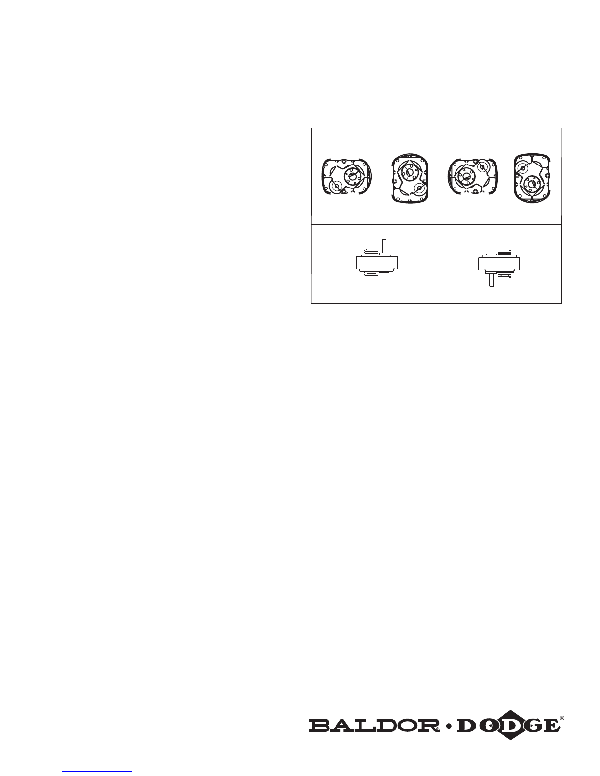
2. Determine the running position of the reducer (Figure 1). Note
that the reducer housing has been machined for pipe plugs
around the sides of the reducer for horizontal applications
and in each face for vertical applications. The plugs must be
arranged relative to the running position as follows:
Horizontal Installations - Install the magnetic drain plug in
the hole closest to the bottom of the reducer. Throw away
the tape that covers the lter/ ventilation plug in shipment
and install plug in topmost hole. Of the remaining plugs on
the sides of the reducer, the lowest one is the minimum oil
level plug.
Vertical Installations -Install the lter/ventilation plug in the
hole provided in the top face of the reducer housing. Use the
hole in the bottom face for the magnetic drain plug. Of the
remaining holes on the sides of the reducer, use a plug in the
upper housing half for the minimum oil level plug.
The running position of the reducer in a horizontal application
is not limited to the four position shown in Figure 1. However,
if running position is over 20° in position “B” and “D” or
5° in position “A” and “C” either way from sketches, the oil
level plug cannot be safely used to check the oil level, unless
during the checking the torque arm is disconnected and the
reducer is swung to within 20° for position “B” or “D” or 5°
for position “A” or “C” of the positions shown in Figure 1.
Because of the many possible positions of the reducer, it
may be necessary or desirable to make special adaptations
using the lubrication tting holes furnished along with other
standard pipe ttings, stand pipes and oil level gauges as
required.
WARNING: Because of the possible danger to person(s) or
property from accidents which may result from the improper
use of products, it is important that correct procedures be
followed. Products must be used in accordance with the
engineering information specified in the catalog. Proper
installation, maintenance and operation procedures must
be observed. The instructions in the instruction manuals
must be followed. Inspections should be made as necessary
to assure safe operation under prevailing conditions. Proper
guards and other suitable safety devices or procedures, as
may be desirable, or as may be specified in safety codes
should be provided, and are neither provided by Baldor
Electric Company, nor are the responsibility of Baldor
Electric Company. This unit and its associated equipment
must be installed, adjusted and maintained by qualified
personnel who are familiar with the construction and
operation of all equipment in the system and the potential
hazards involved. When risks to persons or property may
be involved, a holding device must be an integral part of the
driven equipment beyond the speed reducer output shaft.
TDT13 TDT15
B
P
D
P
D
B=BREATHER D=DRAIN L=LEVEL P=PLUG
Figure 1 - Mounting Positions
CAUTION: Unit is shipped without oil. Add proper amount
of recommended lubricant before operating. Failure to
observe these precautions could result in damage to, or
destruction of, the equipment.
NOTE: TXT12, TDT13 and TDT14: Refer to instruction manual
packed with tapered bushings for installation then go to step 9.
TDT15 only:
3. Place the inboard bushing on the shaft and position it 3½”
away from the bearing.
4. Place output hub key on shaft and in bushing. Stake key in
position.
5. Hoist reducer into position and slide it onto shaft aligning
hub keyway with key.
6. Align unthreaded holes of inboard bushing with threaded
holes of bushing back-up plate. If necessary, rotate the
bushing back-up plate to align holes. Insert screws and
tighten lightly.
7. Place the outboard bushing in position on the shaft aligning
the bushing keyway with the key. Align the unthreaded
holes in the bushing with the threaded holes in the back-up
plate, rotating the back-up plate if necessary. Insert bushing
screws and tighten lightly.
8. Tighten the screws in both bushings alternately and evenly
to 1600 inch-pounds wrench torque.
1
HORIZONTAL APPLICATIONS
B
P
L
B
L
L
D
VERTICAL MOUNT
B
P
L
D
P
D
F-POSITIONE-POSITION
B
P
D
D-POSITIONC-POSITIONB-POSITIONA-POSITION
B
L
L
Page 2
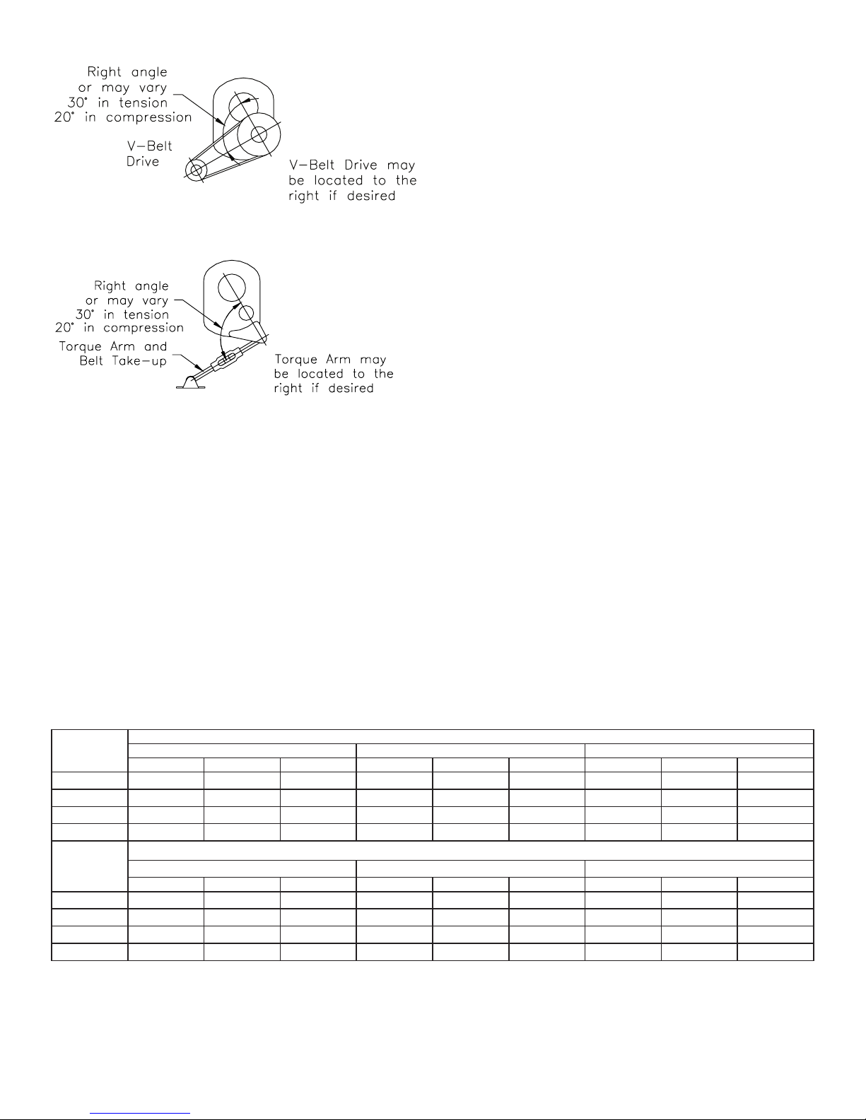
Figure 2 - Positioning
9. Install sheave on input shaft as close to reducer as possible.
10. Install motor and V-belt drive so belt pull will be roughly at
right angles to the center line between driven and input shaft
(Figure 2.) This will permit tightening V-belt drive with the
torque-arm.
11. Install torque-arm adaptor plates on the input end of the
re d ucer.
12. Install torque-arm fulcrum on a rigid support so that the
torque-arm will be approximately at right angles to the
center line through the driven shaft and the torque-arm
anchor screw (Figure 2). Make sure that there is sufcient
take-up in the turnbuckle for belt tension adjustment when
using V-belt drives.
13. Retighten bolts and pipe plugs after a few days' operation.
This prevents oil leakage.
LUBRICATION
NOTE: Because r educer is shipped without oil, it is necessary
to add the proper amount of oil before running.
Use a high-grade petroleum-base, rust and oxidation inhibited
(R&O) gear oil (Tables 1 and 2). Follow instructions on reducer
nameplate, warning tags and in the installation manual.
Under average industrial operating conditions, the lubricant
should be changed every 2500 hours of operation or every 6
months, whichever occurs rst. Drain reducer and ush with
kerosene, clean magnetic drain plug and rell to proper level with
new lubricant.
CAUTION: Extreme pressure (EP) lubricants are not
recommended for average operating conditions. Failure to
observe these precautions could result in bodily injury.
CAUTION: Too much oil will cause overheating and too little
will result in gear failure. Check oil level regularly. Failure to
observe this precaution could result in bodily injury. Under
extreme operating conditions, such as rapid rise and fall
of temperature, dust, dirt, chemical particles, chemical
fumes, or oil sump temperatures above 200°F, the oil should
be changed every 1 to 3 months depending on severity of
conditions.
CAUTION: Do not use EP oils or oils containing slippery
additives such as graphite or molybdenum disulphide in the
reducer when backstop is used. These additives will destroy
sprag action.
Reducer Size
TXT12 188 4 58-7/ 8 55.7 1216 38 36 1884 58 -7/8 55.7
TD T13 2752 86 81.0 19 84 62 59 2752 86 81.0
TDT14 3840 120 114. 0 2816 88 83 3840 12 0 114 .0
TDT15 6304 197 186.0 4416 13 8 131 6144 192 182.0
Reducer Size
TXT12 116 4 36-3/8 34.4 3200 100 95 3200 100 95
TD T13 1888 59 56.0 3520 110 10 4 3520 110 104
TDT14 1952 61 58.0 4800 150 142 4800 15 0 142
TDT15 5440 17 0 161.0 8992 281 266 8992 281 266
NOTES:
① Oil quantity is approximate. Service with lubricant until oil runs out of oil level hole.
② Refer to Figure 1 for mounting positions.
③ US measure: 1 quart = 32 fluid ounces = .94646 liters.
④ Below 20 RPM output speed, oil level must be adjusted to reach the highest oil level plug (P). If reducer position is to vary from those shown in Figure 1, either more or less oil
may be required. Consult Baldor Electric Company, Dodge Product Support, Greenville, South Carolina.
Fluid Ounces ③ Quarts Liters Fluid Ounces ③ Quarts Liters Fluid Ounces ③ Quarts Liters
Fluid Ounces ③ Quarts Liters Fluid Ounces ③ Quarts Liters Fluid Ounces ③ Quarts Liters
② Position A ② Position B ② Position C
② Position D ② Position E ② Position F
Table 1 – Oil Volumes
Volume of Oil to Fill Reducer to Oil Level Plug ① ④
Volume of Oil to Fill Reducer to Oil Level Plug ① ④
2
Page 3

Table 2 – Lubrication Recommendations - ISO Grades *
Output
RPM
301 – 400 150 150 150 150
201 – 300 150 150 150 150
151 – 200 150 150 15 0 150
126 – 150 150 15 0 15 0 150
101 – 125 150 15 0 150 150
81 – 100 150 150 150 150
41 – 80 150 15 0 15 0 150
11 – 40 150 15 0 150 150
1 – 10 220 220 220 220
Output
RPM
301 – 400 220 220 220 220
201 – 300 220 220 220 220
151 – 200 220 220 220 220
126 – 150 220 220 220 220
101 – 125 220 220 220 220
81 – 100 220 220 220 220
41 – 80 220 220 220 220
11 – 40 220 220 220 220
1 – 10 320 320 320 320
NOTES:
Below – 23º F call application engineering.
20ºF to -22ºF use Mobil SHC 627.
Above 125ºF use Mobil SHC 634.
ISO Grades For Ambient Temperatures of 15˚ F to 60˚ F
Torque-Arm Reducer Size
TX T12 TDT13 TDT14 TDT15
ISO Grades For Ambient Temperatures of 50˚ F to 125˚ F
Torque-Arm Reducer Size
TX T12 TDT 13 T DT 14 TDT15
GUIDELINES FOR TORQUE-ARM REDUCER
LONG-TERM STORAGE
During periods of long storage, or when waiting for delivery or
installation of other equipment, special care should be taken to
protect a gear reducer to have it ready to be in the best condition
when placed into service.
By taking special precautions, problems such as seal leakage
and reducer failure due to lack of lubrication, improper
lubrication quantity, or contamination can be avoided. The
following precautions will protect gear reducers during periods
of extended storage:
Preparation:
1. Drain oil from the unit. Add a vapor phase corrosion inhibiting
oil (VCI-105 oil by Daubert Chemical Co.) in accordance with
Table 3 .
2. Seal the unit airtight. Replace the vent plug with a standard
pipe plug and wire the vent to the unit.
3. Cover all unpainted exterior parts with a waxy rust
preventative compound that will keep oxygen away from
the bare metal. (Non-Rust X-110 by Daubert Chemical Co.
or equivalent).
4. The instruction manuals and lubrication tags are paper and
must be kept dry. Either remove these documents and store
them inside, or cover the unit with a durable waterproof
cover which can keep moisture away.
5. Protect reducer from dust, moisture, and other contaminants
by storing the unit in a dry area.
6. In damp environments, the reducer should be packed inside
a moisture-proof container or an envelope of polyethylene
containing a desiccant material. If the reducer is to be stored
outdoors, cover the entire exterior with a rust preventative.
When placing the reducer into service:
1. Assemble the vent plug into the proper hole.
2. Clean the shaft extensions with petroleum solvents.
3. Fill the unit to the proper oil level using a recommended
lubricant. The VCI oil will not affect the new lubricant.
Follow the installation instructions provided in this manual.
Table 3 - Quantities of VCI #105 Oil
Reducer Size Quarts or Liters
TXT12 2.5
TD T13 3.0
TDT14 and TDT15 4.0
VCI #105 and #10 are interchangeable.
VCI #105 is more readily available.
3
Page 4

MOTOR MOUNTS
REPLACEMENT OF PARTS
The motor mount must be installed on output end of reducer as
shown in Figure 3.
Remove two or three (as required) housing bolts on output end
of reducer. Install back support 1 and front support 2 with new
housing bolts 8. Install mounting bolts 3.
Install mounting plate 5 with adjusting studs 4 as shown in Figure
3. Assemble one motor rail 6 by loosely bolting through the
two front holes on each side of mounting plate (Figure 3) with
mounting rail bolts 7.
Measure the distance between front and rear mounting holes of
motor. Position the rear motor rail to this distance and loosely
bolt to the mounting plate.
Center the motor on the motor rails. Use a plain washer under
each slot in the motor rails when the motor mounting bolts are
less than diameter. Bolt motor snugly to motor rails.
Install motor sheave and reducer sheave on their shafts as close
as possible to the motor and reducer housings. Note: The motor
rails may be moved forward or backward from the position
shown in Figure 3 to permit alignment of the V-belt sheaves.
It is permissible for the front motor rail to extend beyond the
mounting plate 5. Align the V-belt sheaves carefully and tighten
all bolts securely.
Install V-belts and adjust belt tension. Figure 3 shows the mount
near the minimum belt center position. To increase the center
distance, loosen the four nuts “A” on the adjusting studs and
tighten the four nuts “B” alternately and evenly until the belts are
properly tensioned.
Check all bolts to see that they are securely tightened.
NOTE: Using tools normally found in a maintenance
department, a Dodge Torque-Arm speed reducer can be
disassembled and reassembled by careful attention to the
instructions following.
Cleanliness is very important to prevent the introduction of dirt
into the bearings and other parts of the reducer. A tank of clean
solvent, an arbor press, and equipment for heating bearings and
gears (for shrinking these parts on shafts) should be available.
The oil seals are contact lip seals. Considerable care should be
used during disassembly and reassembly to avoid damage to the
surface on which the seals rub.
The keyseat in the input shaft, as well as any sharp edges on
the output hub should be covered with tape or paper before
disassembly or reassembly. Also, be careful to remove any burrs
or nicks on surfaces of the input shaft or output hub before
disassembly or reassembly.
Ordering Parts
When ordering parts for reducer, specify reducer size number,
reducer model number, part name, part number, and quantity.
It is strongly recommended that, when a pinion or gear is
replaced, the mating pinion or gear also be replaced.
If the large gear on the output hub must be replaced, it is
recommended that an output hub assembly consisting of a gear
assembled on a hub be ordered to ensure undamaged surfaces
on the output hub where the output seals rub. However, if it is
desired to use the old output hub, press the gear and bearing off
and examine the rubbing surface under the oil seal carefully for
possible scratching or other damage resulting from the pressing
operation. To prevent oil leakage at the shaft oil seals, the smooth
surface of the output hub must not be damaged.
Figure 3 - Complete Drive
NOTE: Belt guard removed for photographic purposes.
WARNING: Do not operate if belt guard is not in place.
If any parts must be pressed from a shaft or from the output hub,
this should be done before ordering parts to make sure that none
of the bearings or other parts are damaged in removal. Do not
press against rollers or cage of any bearing.
Because old shaft oil seals may be damaged in disassembly, it is
advisable to order replacements for these parts.
If replacing a bearing or a shaft, it is advisable to order a set
of shims for adjustment of bearings on the shaft assembly. If
replacing a housing, a set of shims should be ordered for each
shaft assembly because the adjustment of the bearings on each
shaft assembly is affected.
Removing Reducer from Shaft
WARNING: To ensure that drive is not unexpectedly started,
turn off and lock out or tag power source before proceeding.
Remove all external loads from drive before removing or
servicing drive or accessories. Support reducer by external
means before removing from shaft. Failure to observe these
precautions could result in bodily injury.
1. Disconnect and remove belt guard, V-drive, and motor
mount as required. Disconnect torque arm rod from reducer
adapter.
2. Remove bushing screws.
4
Page 5

3. Place the screws in the threaded holes provided in the
bushing anges. Tighten the screws alternately and
evenly until the bushings are free on the shaft. For ease of
tightening screws, make sure screw threads and threaded
holes in bushing anges are clean. A tap can be used to
clean out the threads. Use caution to use the proper size tap
to prevent damage to the threads.
4. Remove the outside bushing, the reducer, and then the
inboard bushing.
Disassembly
1. Drain all oil from the reducer.
2. Remove retaining rings from output hub. Remove bushing
back-up plates.
3. Remove all bolts from housing. Open housing evenly to
prevent damage to parts inside.
4. Lift shaft, gear and bearing assemblies from housing.
5. Remove seals, bearing covers, seal carriers, backstop
carrier and bearing cups from housing.
Reassembly
1. Output Hub Assembly: Heat gear to 325°F to 350°F to
shrink onto hub. Heat bearings to 270°F to 290°F to shrink
onto hub. Any injury to the hub surfaces where the oil seals
rub will cause leakage, making it necessary to use a new
hub. Press output hub wear rings onto the hub until the
distance from the hub end to the far side of the wear ring
ange is: 2-7/32” on TDT13; 2-15/32” on TDT14; or 3-3/32”
on TDT15.
2. Countershaft Assembly: Shaft and pinion are integral.
Heat gear to 325°F to 350°F to shrink on shaft. Heat bearing
cones to 270°F to 290°F to shrink on shaft.
3. Input Shaft Assembly: Slide pinion on shaft. Heat bearing
cones to 270°F to 290°F to shrink on shaft. Press input shaft
wear ring onto shaft until the distance from the shaft end to
the far side of the wear ring ange is: 9-11/16” on TDT13; 123/4” on TDT14; or 14-7/32” on TDT15.
4. Install a .025 shim on input backstop carrier, countershaft
bearing carriers and output seal carrier. Apply a bead of
RTV732 inside carriers at shim I.D. to prevent leaks. Install
the carriers on R.H. housing half and torque to values in
Table 4. Install the input, countershaft and output bearing
cups. Insure cups are seated properly. Place housing on
blocks to allow clearance for protruding end of output hub.
5. Mesh output hub assembly and countershaft assemblies
together and place in housing half. Place input shaft
assembly in position. Make sure rollers are properly seated
in bearing cups. Input pinion and countershaft gears must
be timed for proper sharing of loads. With reducer laying
at on table viewing input shaft, lift up input shell pinion
on input shaft (pinion should slide freely on shaft). Notice
the countershaft gears should rotate equal amounts in
opposite directions. If this occurs, check the shell pinion on
the input shaft for being approximately centered between
the bearings. Using the large gear rotate the gears (in both
directions) and check for smoothness of rotation. No binding
should exist. If countershaft gears rotate equal amounts in
opposite directions, the input shell pinion is approximately
center of the bearings, and gears rotate smoothly. The gears
should be timed properly. If all the above does not occur,
lift one of the countershaft gear sets and rotate one tooth
in either direction and re-mesh gears. Repeat timing check
process. Repeat this procedure until the timing is correct.
Timing of gears is a must for proper operation of the reducer.
Consult Baldor Electric Company, DODGE Engineering in
Greenville, SC for assistance.
6. Clean housing ange surfaces on both halves, making sure
not to nick or scratch ange face. Place a new bead of gasket
RTV 732 on ange face and spread evenly over entire ange
leaving no bare spots. Place other housing half into position
and tap with a soft hammer until housing bolts can be used
to draw housing halves together. Torque housing bolts per
torque values listed in Table 4.
7. Place output seal carrier into position without shims.
Install four bolts and torque to 25 lb-ins. Rotate output hub
assembly to seat bearings. Torque bolts to 50 lb-ins. Again
rotate the output hub to seat bearings (tap down on output
hub with rawhide mallet while rotating). Using feeler gauge
check gap between carrier ange and housing. Remove
carrier, add gap measurement plus .002 shims, reinstall
carrier and torque bolts to values in Table 4. Using dial
indicator check end play of hub assembly. End play value is
.001 to .003. Add or remove shims to obtain proper setting.
8. Repeat process for the countershaft assemblies. End play
value is .001 to .003.
9. Repeat the process for the input shaft. End play value is .002
to .004.
Note: Apply 1/8” bead of RTV732 inside carriers at I.D. of
shims to prevent leaks.
10. Extreme care should be used in installing seals on input
shaft and output hub to avoid damage which would result
in oil leakage. This danger of damage and consequent oil
leakage can be decreased by covering the keyseat and
retaining ring groove with scotch tape or paper which can
be removed subsequently. Chamfer or burr housing bore if
end of bore is sharp or rough. Fill cavity between lips of seat
with grease. Seals should be pressed or tapped with a soft
hammer evenly into place in the housing, applying force only
on outer corner of seals. A slight oil leakage at the seals may
be evident during initial running in, but will disappear unless
the seals have been damaged.
Table 4 - Recommended Torque Values (lb.-in.)
Reducer Size Housing Bolts
TXT12 1620 3120 180 0
TD T13 1620 312 0 1800
TDT14 312 0 516 0 312 0
TDT15 312 0 516 0 3120
Table 5 - Replacement Output Hub Bearings
Reducer Size
TXT12 402039 40 3119
TD T13 402230 402229
TDT14 402239 403133
TDT15 402009 4030 13
Table 6 - Replacement Countershaft Bearings
Reducer Size
TXT12 40 2127 403089
TD T13 402234 402233
TDT14 402240 4 0 313 4
TDT15 402 0 11 4030 14
Table 7 - Replacement Input Shaft Bearings
Reducer Size
TXT12 40 2125 403087 402125 403087
TD T13 402232 402231 402232 402231
TDT14 402241 402233 402241 402233
TDT15 402234 402233 402241 402233
Input End Part No. Backstop End Part No.
Cone Cup Cone Cup
Output Hub
Seal Carrier
Part No.
Cone Cup
Part No.
Cone Cup
Countershaft &
Input Shaft
Carrier & Cover
5
Page 6

Parts for TXT12, TDT13, TDT14 and TDT15
Note: The two-digit numbers are for
reference use. Order parts by the six-digit
part numbers in the Parts List whenever
possible. Each six digit number is a
complete identication of the part of the
assembly.
Taper Bushed Reducers
6
Page 7

Parts for TXT12, TDT13, TDT14 and TDT15
Taper Bushed Reducers
Ref. Description
Backstop Assembly 1 250260 272259 272293 272293
12
Housing
Air Vent with Bushing
15
Housing Bolt
16
Adapter Housing Bolt
18
Lockwasher
20
Plain Washer
22
Hex Nut
24
Dowel Pin
26
Pipe Plug
30
Magnetic Plug
32
Input Shaft Seal Carrier
34
Input Shaft
38
Bearing Shim Pack
Backstop Carrier
40
Carrier & Cover Screw
42
Countershaft Cover Screw
43
Lockwasher
44
Backstop Cover
46
Backstop Cover Gasket
48
Backstop Cover
50
Cap Screw
Lockwasher
52
Input Shaft 1 272004 272261 272161 272362
54
Input
56
Pinion
Input Shaft Seal 1 27 2 211 272270 272270 272377
58
Input Shaft
60
Seal Wear Ring
62
Input Shaft Key
Input Shaft Bearing Cone -
63
Input End
Input Shaft Bearing Cone -
64
Backstop End
Input Shaft Bearing Cup
66
Input Shaft Bearing Spacer
67
Countershaft
Assembly
Left Hand
Spiral
⑦ Countershaft
with Pinion 1 272006 272265 272165 272366
68
L.H. 1st
70
Reduction
Gear
⑦ Key 2 248218 248 218 248218 272389
72
Countershaft
Assembly
Right Hand
Spiral
⑦ Countershaft
with Pinion 1 272006 272265 2 72165 272366
68
⑦ R.H. 1st
71
Reduction Gear
15:1 Ratio
⑤ Ratio
⑦ Key 2 248218 248 218 248218 272389
72
Countershaft Bearing Cone
74
Countershaft Bearing Cup
76
Countershaft Bearing Spacer
78
Countershaft Bearing Cover
80
Plug
84
15:1 Ratio
⑤ Ratio11
15:1 Ratio
⑤ Ratio11
15:1 Ratio
⑤ Ratio
15:1 Ratio
⑤ Ratio1 1
Number
Required
② Sets ③
TX T12
Part No.
1
252 163
1
2710 41
12
4115 0 6
4
411508
16
4190 16
2
4190 82
16
407095
2
42013 2
①
430035
1
430064
1
272019
39 215 0
1
272020
16
4114 8 3
32
4114 8 3
48
4190 14
1
248221
1
248220
6
4114 02
6
4190 09
2722 12
272003—272262—272162—272363
1
1
44 3122
1
40 2125
1
40 2124
2
403087
1
1 272026
272005—272263—272163— 272364
1
272028
1
27 2 011— 272264— 27 116 4— 272365
4
40 2127
4
403089
2
2720 17
4
272016
4
430035
TDT13
Part No.
272255
2710 41
4115 09
4114 5 3
4190 16
4190 82
407095
42013 3
430035
430064
272274
39 215 0
272275
4114 8 3
4114 8 3
4190 14
272278
272277
4114 0 8
419 011
—
272281
44 314 0
402232
402232
402231
—
‡
‡
‡
‡
—
—
‡
—
‡
402234
402233
272268
272273
430035
TDT14
Part No.
27215 5
2710 41
411517
411518
4190 20
419080
407099
42013 4
430035
430064
27 2174
39 215 5
272175
4112 68
4112 68
4190 16
272176
27217 7
4114 07
419 011
272281
44 3139
402241
402241
402233
—
—
‡
—
‡
402240
40 313 4
272168
272173
430035
TDT 15
Part No.
272371
2710 41
411245
411247
4190 20
419080
407099
42013 5
430035
430064
272381
39 215 5
272175
4112 68
4114 95
4190 16
272176
27217 7
4114 07
419 011
272376
443348
402234
402241
402233
272391
—
‡
—
‡
40 2011
40 3014
272372
272380
430035
Parts for TXT12, TDT13, TDT14 and TDT15
Taper Bushed Reducers
Ref. Description
Countershaft Bearing
86
Shim Pack
Output Hub Assembly
⑦ Output Hub
88
⑦ Output Gear
90
⑦ Gear Key & Roll Pin
92
Bushing Back-up Plate
94
Retaining Ring
96
5-7/16” Bore
5-15/16” Bore
6” Bore
⑦ Key
Shaft
6-7/16” Bore
6-1/2” Bore
7” Bore
8” Bore
8-1/2” Bore
9” Bore
10” Bore
5-7/16” Bore
5-15/16” Bore
6” Bore
6-7/16” Bore
6-1/2” Bore
7” Bore
8” Bore
8-1/2” Bore
9” Bore
10” Bore
Bushing
Assembly
98
100
Bushing to
102
⑦ Bushing Screw
104
⑦ Lockwasher
106
Output Hub Seal
108
Output Hub Seal Wear Ring
110
Output Hub Seal Carrier
114
Carrier Screw
116
Lockwasher
118
Output Hub Bearing Cone
120
Output Hub Bearing Cup
122
Output Hub Bearing Spacer
124
Output Hub
Bearing Shim Pack
126
Rod End
128
Hex Nut
130
Turnbuckle
132
Extension
134
L.H. Hex Nut
136
Fulcrum
138
Fulcrum Screw
Adapter Assembly
140
⑦ Adapter Plate
142
⑦ Adapter Bushing
144
⑦ Adapter Bolt
146
⑦ Lockwasher
148
⑦ Hex Nut
NOTES:
① 9 required on TXT12; 12 required on TDT13 and TDT14; 16 required on TDT15.
Number
Required
⑧ Sets ③
⑧ Sets ③
② 4 sets required on TXT12, TDT13 and TDT14; 6 sets required on TDT15.
③ If replacing a bearing or a shaf t, it is advisable to order a set of shims for adjustment of
bearings on the shaft assembly. If replacing a housing, a set of shims should be ordered
for each shaft assembly because the adjustment of the bearings on each shaft assembly
is affected.
④ 25:1 on TXT12, TDT13 and TDT14; 30:1 on TDT15.
⑤ Includes parts listed immediately below. Housing assembly also includes a two-piece
housing. Bushing assembly includes 2 bushings.
Makes up assembly under which listed.
⑦ 2 sets required on TXT12, TDT13 and TDT14; 3 sets required on TDT15.
⑧ Use reference number when ordering giving complete part identification.
16
16
TX T12
Part No.
39 2151
1
1
272220
1
272007
3
390859
2
272221
2
4210 53
1
2722 15
1
272216
1
2722 17
1
272218
1
272219
1
1
1
1
1
1
272223
1
272225
1
272227
1
272229
1
272231
1
1
1
1
1
8
4114 8 5
8
4190 14
2
272010
2
2
272014
4114 93
4190 16
2
402039
2
40 3119
1
2720 12
39 215 2
1
272050
1
407108
1
272051
1
272052
1
407251
1
272054
1
411524
1
2
272049
1
272046
1
411520
2
4190 24
2
407104
TDT13
Part No.
39 215 3
⑨
390969
272267
272266
390863
272283
4210 95
272290
272291
272292
—
272257
—
—
—
—
272287
272288
272289
—
44 3175
—
—
—
—
4114 8 5
4190 14
272271
—
272282
272272
4114 93
4190 16
402230
402229
272269
39 215 4
272050
407108
272051
272052
407251
272054
411524
—
272280
272046
411520
4190 24
407104
TDT14
Part No.
39 215 6
272167
272166
390865
272183
4210 96
—
272191
—
272192
272193
—
272194
—
—
—
—
272188
—
272189
272190
—
44 318 8
—
—
—
4114 95
4190 16
272171
272182
272172
411276
4190 18
402239
40 313 3
272169
39 215 7
272151
40 7110
272152
27215 3
40 7111
27215 4
411528
—
272180
272187
411527
4190 25
407108
TDT 15
Part No.
39 215 8
⑨
—
—
—
—
—
—
—
—
—
—
—
—
—
⑨
272368
272367
389899
272390
42 1114
—
—
—
—
—
—
272398
272397
272396
272395
—
—
—
—
—
—
272408
272407
272406
443349
4114 96
4190 16
272375
27 2 374
272379
411248
4190 18
402009
40 3013
272378
39 215 9
272385
40715 0
272386
272387
407080
272388
411245
—
272383
272384
411244
4190 26
40 7110
7
Page 8

OIL VISCOSITY EQUIVALENCY CHART
KINEMATIC
VISCOSITIES
cSt/
40°C 100°C
2000
1000
800
600
500
400
300
200
100
80
60
50
40
30
20
10
8
6
5
4
3
2
cSt/ ISO
70
60
50
40
30
20
10
9
8
7
6
5
4
VG
1500
1000
680
460
320
220
150
100
68
46
32
22
15
10
7
5
3
2
AGMA
GRADES
8A
8
7
6
5
4
3
2
1
VISCOSITIES CAN BE
RELATED HORIZONTALLY
ONLY.
VISCOSITIES BASED ON
96 VI SINGLE GRADE
OILS.
ISO ARE SPECIFIED AT
40°C.
AGMA ARE SPECIFIED AT
40°C.
SAE 75W, 80W, AND 85W
SPECIFIED AT LOW
TEMPERATURE. EQUIVALENT
VISCOSITIES FOR 100°F
AND 200°F ARE SHOWN.
SAE 90 TO 250 SPECIFIED
AT 100°C.
SAE
GRADES
GEAR OILS
250
140
90
85W
80W
75W
SAYBOLT
VISCOSITIES
SUS/
100°F
10,000
8000
6000
5000
4000
3000
2000
1500
1000
800
600
500
400
300
200
150
100
80
70
60
50
40
35
32
SUS/
210°F
300
200
100
90
80
70
60
55
50
45
40
Figure 4 - OIL VISCOSITY EQUIVALENCY CHART
P.O. Box 2400, Fort Smith, AR 72902-2400 U.S.A., Ph: (1) 479.646.4711, Fax (1) 479.648.5792, International Fax (1) 479.648.5895
6040 Ponders Court, Greenville, SC 29615-4617 U.S.A., Ph: (1) 864.297.4800, Fax: (1) 864.281.2433
© Baldor Electric Company
MN1630 (Replaces 499353)
*1630-0617*
Dodge Product Support
www.baldor.com
All Rights Reserved. Printed in USA.
06/17 Printshop 200
 Loading...