

Page 1

BSC Series 2000/ 3000
Servo Control
7/92
Installation & Operating Manual
Page 2

C O N T E N T S
1.0 Specifications ............................... 1
1.1 Usage Definitions ....................... 1
1.2 Identification .............................. 1
1.3 Features ..................................... 1
1.4 Declaration of Conformity .......... 2
1.5 EMC Conformity and CE Marking 2
1.5.1 EMC Installation Instructions ..... 2
1.5.2 Specifications add components .. 3
1.5.2.1 Mains Filters .............................. 3
1.5.2.2 Connection Cables ..................... 4
1.5.2.3 Screen Connections .................... 4
1.5.2.4 Connectors ................................ 4
1.5.2.5 PG-Cable Glands ....................... 5
1.6 Technical Data ........................... 5
1.6.1 Power Section ............................ 5
1.6.2 24VDC Input ............................. 6
1.6.3 Velocity Controller .................... 6
1.6.4 Mechanical Section .................... 6
1.6.5 Environmental Section ............... 7
2.0 Installation Recommendations .... 7
2.1 Mechanical Installation ............... 7
2.2 Electrical Installation .................. 8
3.0 Interconnection Diagram ............. 9
4.0 BSC Wiring .............................. 10
4.1 Power Wiring ............................. 10
4.1.1 Power Supply ............................. 10
4.1.2 24VDC Connection .................... 10
4.1.3 Motor Wiring ............................. 10
4.2 Control- and Signal Wiring ......... 11
4.2.1 Control Inputs ............................ 11
4.2.2 Control Outputs ......................... 12
4.2.3 Command Input ......................... 13
4.2.4 Encoder Output ......................... 13
4.2.5 Resolver ..................................... 13
4.3 Minimum Wiring Diagram .......... 14
5.0 Dimensions ................................... 16
6.0 System Set Up Procedure ............ 18
6.1 Presets ....................................... 18
6.1.1 Potentiometer Preset .................. 18
6.1.2 DIP-Switches Settings ................ 18
6.2 System Set Up Step by Step ....... 19
6.3 System Tuning ........................... 20
7.0 Status Monitor ............................. 22
8.0 Testsignals .................................... 23
9.0 Identity Modul ............................. 23
9.1 Component Functions ................ 23
9.2 Component Layout .................... 24
10.0 I/O Hardware Description ........... 24
10.1 Input Signals .............................. 25
10.2 Output Signals ........................... 26
10.3 Encoder Output ......................... 27
10.3.1 Encoder Signals ......................... 27
10.4 Resolver ..................................... 28
Page 3

1
L
1.0 Specification
1.1 Usage Definitions
The amplifiers of the series BSC2000/3000 are electrical equipment for industrial power installations. They are designed for
machine applications, which need variable speed controlled three-phase A.C. motors.
This product is only for use in industrial applications as described in norms EN 60204 and VDE 0160. This means use
BSC2000/3000 in stationary groundbased applications only. It is not meant for use in home appliances, medical technics,
cars, ships or airplanes.
Before the BSC is put into operation, please contact your Electric-Supply-Company for special operating conditions.
1.2 Identification
BSC x x xx - xx
24 - External 24VDC-I nput
{
MR - Multiresolvercard
15
25
Nomin al C urrent (Amps)
35
{
45
1.3 Features
A BSC is an analog 1 axis amplifier with integrated power stage.
It provides the following features:
POWER SECTION:
• 3 respectively 4 output current versions (15/25/35/45A)
available.
• Ratio peak : nominal current = 2:1.
Both values independently adjustable.
• All BSC amplifiers are short circuit proof and require
no minimum load.
CONTROL I/O Section:
• 5 opto isolated control inputs for dedicated amplifier
functions
• Diagnostic display on front panel
GENERAL:
• Protection class IP20 (acc. to DIN40 050 / IEC144)
• Cooling: self-ventilation
20 : Series 2000
{
30 : Series 3000
BALDOR-SERVO-CONTRO
• Output power up to 30kVA
• Brushless-servomotors (2 to 8 poles) can be connected.
(Feedback: 2-pole resolver)
• Power wiring via terminal screws (max. wiring diameter
10mm²/AWG7)
• Wiring of control inputs and outputs via plug type
screw connection (max. wiring diameter 1,5mm²/
AWG15) or SUB-D connector
• Isolation classification according to DIN 0110 with
overvoltage category II
• Contamination level 2
Page 4

2
1.4 Declaration of Conformity
Herewith we declare, that our products are components only and not ready for immediate or instant use within the meaning
of "Safety law of appliance", "EMC Law" or "Machine directive".
The final mode of operation is defined only by the insertion into the user´s construction.
It is the responsibility of the user to verify that his construction is in accordance with existing regulations.
It is prohibited by law to put the machine into operation before verifying that the machine is in accordance with EC directive
89/392 and 921/368.
The supplier declares product conformity with the following standards:
DIN VDE 0160 / 05.88 Electronic equipment for use in electrical power installations
DIN VDE 0100 Erection of power installations with nominal voltages up to 1000V
DIN IEC 326 Part 1 / 10.90 Design and use of printed boards
DIN VDE 0110 Part 1-2 / 01.89 Dimensioning of clearance and creepage distances
DIN VDE 0110 Part 20 / 08.90
EN 60529 / 10.91 Degrees of protection provided by enclosures
1.5 EMC - Conformity and CE - Marking
The application of EMC conformal component and partly systems relieves the observance of EMC Guidelines and the
guaranty of conformity for the manufacturer of machines. Therefore all standard components and partly systems will be
tested according to the requirements of EMC regulation. Those tests will be executed by a competent and indepen-dent
institution. The conformity of the products will be confirmed by a declaration of conformity from the European Community.
The installation instructions refer to elimination of radio interference as well as to immunity from noise for BALDOR Drive
Systems.
Thereby the user is informed about the EMC critical parts. The examples don´t show the complete possibilities of cabinet
components or constructions.
Guidelines for EMC Conformity
⇒ Machine Guideline (89/392/EWG) - Machine Safety Law
Application since 01.01.95
⇒ EMV Guideline (89/336/EWG) - EMC Law
Applicade 01.01.96 on
⇒ Low Voltage Guideline (73/23/EWG) - Machine Safety Law
Applicade 01.01.97 on
1.5.1 EMC Installation Instructions
To ensure electromagnetical compatibility (EMC) at hostile environment inside the cabinet following instructions are to be
observed for construction. Only the implementation of following provisions enables the reduction of interference down to
required values.
For the Drives Technology following key points are to be considered:
- Grounding
- Screening
- Filtering
Page 5

3
Furthermore the relevant chapters of the Installation manual for the controllers have to be observed.
For installation of the drives system the starting point is the installation into a cabinet.
For construction of a cabinet the following installation instructions have to be considered:
A) All metal conducting parts of a cabinet are to be connected arealy and conductable.Eventually
the connections should be placed with an earthing strap at a central grounding point .
B) Signal lines and Power Cables are to be connected separately. (Avoid interaction space)
C) The screen connection of the signal lines and the power cables has to be ensued on a screen linequaranteeing
enough space. This screen line also has to be conductable and connected to
the remaining housing parts.
D) The cable to the regeneration resistor has to be screened. The screen connection should be on
both sides.
E) The mounting of the mains filter has to be situated at the input of the cabinet or behind the transformer. The
filter is to connect on ground (cabinet housing, mounting plate etc.).
F) Wiring has to be conducted bundled and close to the cabinet housing or at the mounting line.
The unused leads of a cable have to be connected on one side with ground.
G) In case of worse potential balance between the screen connections a compensating leak with at least
10mm2 (AWG) has to be provided parallely in addition to reduction of the screen current.
1)
Grounding in general describes all metal parts which can be connected to a protective conductor, e.g. housing of
switch cabinet, motor housing, fundament grounder.
1)
1)
1.5.2 Specifications and Additional Components
1.5.2.1 Mains Filter
Following results are desired through the application of mains filters:
The electronic system should be protected from high frequency interferences which could enter via the mains cable
(immunity from noise) and vice versa the mains cable may not transmit interferences from the electro-nic systems to
the adjoining components (elimination of radio interference).
In the main line a mains input filter has to be provided between transformer and controller
(In case of direct connecton this has to be in front of the controller).
To choose the fitting mains filter types following points have to be considered:
1. The need of power of the connected controller. Thereby the capacity an d the ability of peak phase current has to be
considered.
2. The required or prevailing mains impedance.
This table shows the corresponding mains filter types for 3 phase input:
Type
FN 351 - 8 - 29
FN 351 - 16
FN 351 - 25
FN 351 - 36
FN 351 - 50 - 29
FN 351 - 80 - 29
FN 351 - 110 - 29
Rated Voltage
[V]
3x 440 8 16 8.0 1.8 24667
3x 440 16 16 9.0 1.8 24668
3x 440 25 170 9.0 3.0 24669
3x 440 36 170 10.5 3.0 24670
3x 440 50 190 12.5 3.1 24671
3x 440 80 210 26.0 9.5 24672
3x 440 110 210 28.0 9.5 24673
Rated Current
(at 40°C)
[A]
Leakage
Current
[mA]
Power
Losses
[W]
Weight
[kg]
BALDOR
-
ID-No
Page 6

1.5.2.2 Connection Cables
All cables have to be screened.
Motorcable and Signalcable
Motorcable 4 x 1.0 mm2 21599
Motorcable 4 x 2.5 mm2 21364
Motorcable 4 x 6.0 mm2 21597
Resolvercable 3 x [2 x 0.14 mm2] 19413
Regen Resistorcable 3 x 2.5 mm2 11302
1.5.2.3 Screen Connection
4
BALDOR
ID - No.
5mm Rail Wiring Diameter
10mm Rail
for T- and double T-profile
1.5.2.4 Connectors
Connection Designation BALDOR - ID -No.
for Motorcable
Plug
Socket
for Resolvercable
Plug
Socket
Connector
Housing
Siemens Clamp Siemens -No.
2
1.5 - 16 mm
1.5 - 35 mm
16 - 70 mm
16 - 120 mm
Wiring Diameter
95 - 300 mm
CONN SET FEM
CONN SET MALE
CONN SET FEM
CONN SET MALE
for BSC with EMC-Regulation
connector X2 with housing
2
2
2
2
8US19 21 -2AA00
8US19 41 -2AA00
2 x 4 pole
2 x 4 pole
12/6 pole
12/6 pole
25043A
25049A
-2AB00
-2AD00
-2AC00
24654A
24656A
24655A
24657A
Page 7

1.5.2.5 PG - Cable Glands
PG Cable Gland Cable Dimensions Designation BALDOR
PG 9
PG 13.5
PG 21
4 - 8 mm
Resolvercable
BALDOR ID-No.19413
6 - 12 mm
Motorcable
BALDOR ID-No. 21599
13 - 18 mm
Motorcable
BALDOR ID-No. 21364
1.6 Technical Data
All values at T
= 40 °C, if not otherwise specified.
amb
1.6.1 Power Section
5
ID - No.
SCREWING 24658
SCREWING 24659
SCREWING 24660
General Unit BSC
2015
Nominal DC-Bus-Voltage
Uin (BPS) = 230V
Nominal DC-Bus-Voltage
Uin (BPS) = 400V
Nominal DC-Bus-Voltage
Uin (BPS) = 460V
DC-Bus-Voltage
absolute min./max.
Output Voltage Line/Line
fundamental wave; @V
Nominal Phase Current (±10%) A
Peak Phase Current (±10%)
1.5s ±0.5s
Nominal Output Power kVA 6.5 10.8 15.1 19.5 13.0 21.6 30.3
Efficiency % > 95
Min. Load Inductance μH 200
DC-Bus (nom.)
VDC 320 -
VDC - 560
VDC - 650
VDC 0 ... 350 0 ... 740
V
0 ... 250 0 ... 500
RMS
15 25 35 45 15 25 35
RMS
A
30 50 70 90 30 50 70
RMS
BSC
2025
BSC
2035
BSC
2045
BSC
3015
BSC
3025
BSC
3035
Output Frequency Hz 0 ... 500
Nominal Switching Frequency kHz 8.5
Page 8

6
1.6.2 24V
24V-Input Unit BSC2000 BSC3000
DC
Input
Input Voltage Range
absolute min./max.
max. V
Input Current; @ 28VDC A
Surge Current at Power On
@ 28VDC; @ 100ms
Ripple
= ±10%
VDC
1.6
RMS
A
2.5
RMS
20 ... 29
1.6.3 Velocity Controller
Preamplifier Unit BSC2000 BSC3000
Command Input VDC 0 .. ±10
Drift (velocity controller) rpm/K 0.4
Balance (velocity controller) rpm typ. 8 ; adjustable to 0
Resolverfeedback Unit BSC2000 BSC3000
Resolution bit 12
Encoder-Simulation ppr 250 / 500 / 1000 / 1024
Signal 5V TTL ; A;A/; B;B/; C;C/
Reference Pulse available; non adjustable
1.6.4 Mechanical Section
Mechanical Unit BSC2000 BSC3000
Mounting - Bookstyle or Thru the Wall
Dimensions mm 105 x 357 x 328 / 140 x 357 x 328 1)
Weight kg 8.5 / 9.5 1)
1) : BSC2045/3035
Page 9

7
1.6.5 Environmental Section
Environmental Unit BSC2000 BSC3000
Operating Temperature Range °C +5 ... +45
Storage Temperature Range °C -25 ... +70
Humidity % 10 ... 90; not condensating; according to DIN40 040, Class F
Class of Protection (Enclosure) - IP20; according to DIN40 050 / IEC 144
Max. Installation Altitude / M.S.L. m 1000
Shock - 10G; according to DIN IEC 68-2-6/29
Vibration - 1G; 10 ... 150 Hz; according to DIN IEC 68-2-6/29
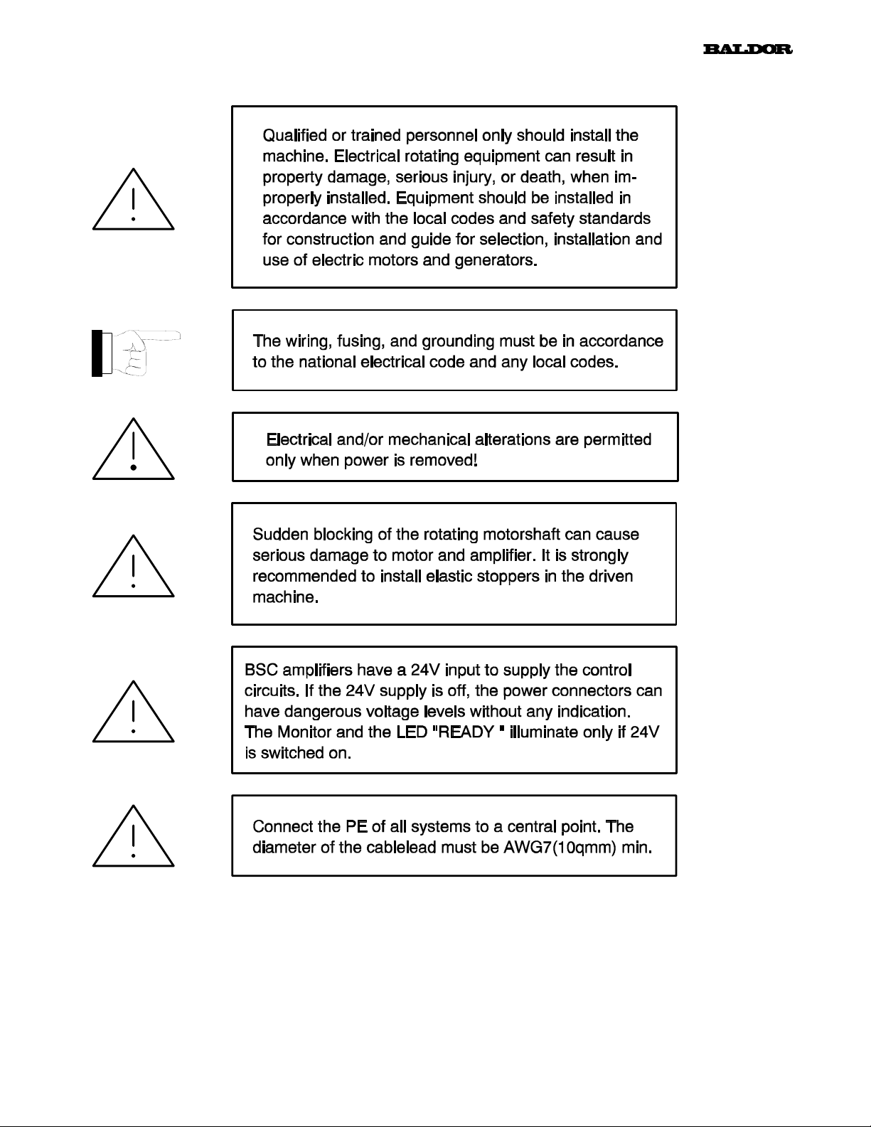
Legend:
This is an INFORMATION sign.
If this information is read, installation and / or
amplifier operating problems can be avoided
in advance.
This sign means ATTENTION.
In all cases it must be read and taken into
account.
Non-observance can cause dangerous situations
for equipment and personnel.
2.0 Installation Recommendations
2.1 Mechanical Installation
- For installation of your system use a cabinet with a protection class that suits your environmental conditions.
- As cooling air freely enters the unit, the environment must be free from corrosive chemical substances, oil, vapour,
steam, metal particles and dust.
- Make sure that cooling is provided.
- Make sure that the top of the unit is covered during installation to prevent particles from falling into the unit.
- Keep DC-bus links as short as possible. Therefore always mount BSC2000/3000-combinations side by side.
- Mount all BSC vertical (Terminal blocks to the top).
- Use BSC2000/3000 in stationary groundbased applications only.
Page 10
2.2 Electrical Installation
8
Page 11

3.0 Interconnection Diagram
9
Content of delivery: mating connector to X1 - 4 and X10. Order-no´s for mating connectors (spare part or completion):
X2: #16000 (20 pole, female); X3: #20506 (8 pole, female); X4: #17934 (10 pole, female); X5: #16215 (9 pole, male)
Connector X4 is reserved for option Multi-Resolver (Absolute positioning). For interconnection diagram refer to manual
Multi-Resolver.
Page 12

10
4.0 BSC Wiring
In chapter 4.3 you will find the typical (minimum) wiring of the system . The following pages show some special
applications and the typical wiring in more detail.
This chapter is valid for all BSC versions.
ATTENTION: For the system set up (chapter 6) it is nessesary to wire the system step by step.
It is recommended to follow the system set up procedure, especiallly for users who are not
very familar with the BSC amplifier series.
4.1 Power Wiring
4.1.1 Power Supply
The BSC amplifier will be supplied from a BPS with the DC-bus voltage. The connection between BSC and BPS must be as
short as possible. The wiring can be done with copper bars (#23176).
Wiring Power Supply:
Chapter 4.3 shows the wiring in detail
4.1.2 24V
A BSC2000/3000 needs an external 24V control supply. This voltage supplies the amplifiers control circuits.
The advantage is, if main power is switched off, control circuits are still supplied and position information gets not lost.
This supply must be linked to BSC connector X10 (Pin 1 and 2). The BPS2000/3000 provide the needed 24V output. This
output is for that purpose and has the same denotation on BPS.
If the BSC is not supplied with the BPS, an external power supply must be connected to connector X10.
The external power supply must fullfil certain specifications (see chapter 1.6.2).
Wiring 24VDC-option:
- Connection
DC
1) The shown BPS, can be replaced by an external 24V-power-supply.
The amount of connected BSC´s (n) which can be connected to one BPS, is "5"
(refer to BPS2000/3000 manual)
2) The wiring of X10 pin 3 and 4 is nessesary for proper BSC operation. For details please refer to chapter
4.2.1.
4.1.3 Motor Wiring
The motor must be connected to the following terminals:
U Phase U
V Phase V
W Phase W
Page 13

A wiring example is shown in chapter 4.3.
11
4.2 Control- and Signal Wiring
This chapter is valid for all BSC versions.
The wiring of the control in- and outputs can be achieved with one cable only unlike shown in the pictures below.
The outputs can be wired. But there is no need for BSC operation.
4.2.1 Control Inputs
The control inputs below are optoisolated. The ground return for all inputs is "CREF", connector X2.14.
Control Input Function:
Signalname Connector Switch Position / Function
Pin closed open
ENABLE X2.9 Amplifier enabled Amplifier disabled
EMStop X2.10 Amplifier is active Motor decellerates with torque to velocity 0
CWLimit X2.11 Clockwise direction of rotation enabled Clockwise direction of rotation disabled
CCWLimit X2.12 Counterclockwise direction of rotation
enabled
CurrentC X2.13 Current Mode active Velocity Mode active
A wiring proposal for the control inputs above you will find in chapter 4.3. The hardware description of the optoisola-
ted input is show in chapter 10.1.
About CurrentC (X2.13):
It is not permitted to activate or deactivate the input during amplifier is operating. The controller behavior
is completely different. The input should be fixed wired.
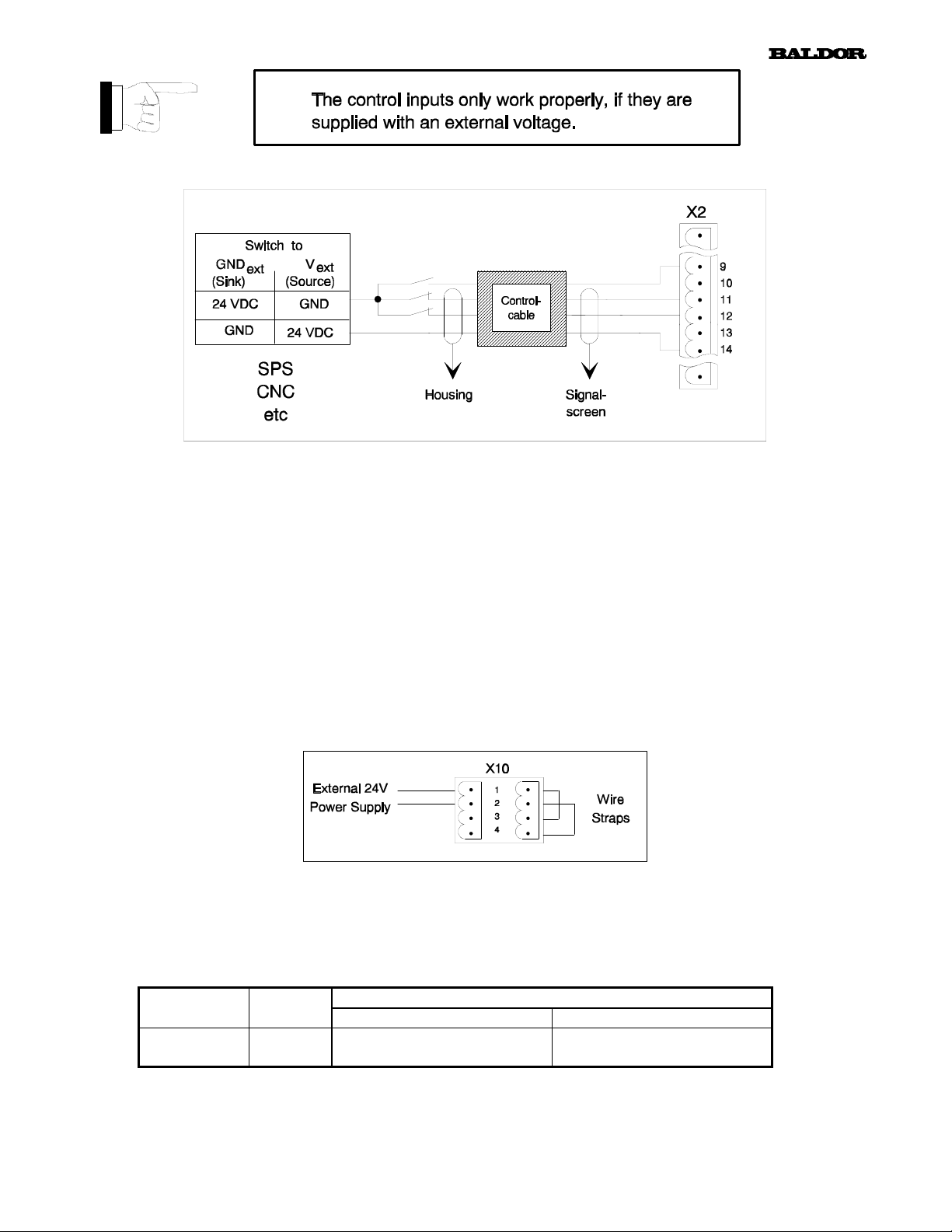
Functional example of control inputs:
The wiring of the control inputs is also shown in chapter 4.3 .
The picture by-stander shows the function and the two
wiring principles of the control inputs:
The two wiring versions are:
1) Switching to the external control input power supply.
The switch will be linked between the control input
(X2.x) and the external power supply (V
The ground return (GND
with CREF (X2.14).
2) Switch to the ground return of the external power
supply. The switch will be linked between the control
input and the external ground return (GND
The external power supply (V
wired with CREF (X2.14).
Voltage range of V
: +12 ... 29VDC
ext
) is permanetly wired
ext
) is permanently
ext
ext
).
ext
).
X2.x: "x" for connector pin,
e.g. x=9 → X2.9 = Enable-Input
Counterclockwise direction of rotation
disabled
Page 14
12
Control Input Wiring:
Control Input "±BPS Ready"
a) BSC with BPS2000/3000:
The BSC provide as default a control input "BPS Ready". If the BPS2000/3000 has an internal malfunction, the BPS will
disable the connected BSC amplifiers. The input is on connector X10 pin 3 and 4.
Under BPS fault condition, this input will be deactivated and the BSC will show the following state:
LED Ready = RED
Monitor = 2 (Undervoltage)
With this fault indication the BSC will be disabled.
b) BSC with external 24V Power Supply:
If the BSC is not operated with the BPS, an external power supply must be connected to connector X10 as shown below. In
that case, the control input "±BPS Ready" has no more function. Nevertheless the input must be wired. Without the wiring
below, the BSC will indicate fault condition like above (see a)).
4.2.2 Control Outputs
The BSC is equipped with a fault relais. The relais contact can be used to observe the amplifier status. The wiring of the fault
relais contact is optional and not nessesary for proper amplifier operation.
Control Output Function:
Signalname Connector Switch Position / Function
Pin closed open
FAULT+
FAULT -
Control Output Wiring:
see chapter 4.3
X2.15
X2.16
BSC happy
no fault indication
BSC not happy
fault indication / monitor
Page 15

13
4.2.3 Command Input
The BSC has an analog command input (±10V). The input can be wired in "single-ended" or in "differential mode".
Wiring of the command input:
4.2.4 Encoder Output
The BSC has an encoder output, which can be used for position- and/or velocity feedback for a superset controller.
The encoder output resolution (pulse per revolution; ppr) can be configured via software. The following binary resolu-tions
are available with the BSC20xx/30xx-Axx version:
250ppr 500ppr 1000ppr 1024ppr
Wiring of the encoder output:
A wiring proposal is shown in chapter 4.3.
It is strongly recommended to make the wire connection with twisted pairs and screened cable.
We recommend the use of the BALDOR encoder cable #13036.
4.2.5 Resolver
The resolver must be connected to connector X9.
Wiring of the resolver in- and outputs:
The wiring is shown in chapter 4.3.
We recommend the use of the special BALDOR resolver cable #19413.
Page 16

14
4.3 Minimum Wiring Diagram "The wiring proposal gives no warranty for
1) The power supply must be wired according to the BPS2000/3000 manual (#22705A)
2) Motorcable: # 21599: Wire diameter: 1.0mm² / AWG17 Cable outer diameter: (11.6 ±0.4)mm
# 21364: Wire diameter: 2.5mm² / AWG13 Cable outer diameter: (14.5 ±0.5)mm
# 21597: Wire diameter: 6.0mm² / AWG9 Cable outer diameter: (18.5 ±0.6)mm
3) Terminal box BSM 6R, BSM90A/90B/100A/100B
4) Connector BSM 63/80 Europe
5) The wiring diameter must fit to nominal BPS output current. The connection between BPS and the BSC ampli-
fiers must be as short as possible.
The wiring between BPS and BSC can be done with copper bars (ID-No.: #23176). Also wiring between BSC´s
can be done with copper bars. ID-No´s.: #23177 (105mm housing) #23179 (140mm housing)
# 21598: Wire diameter: 10mm² / AWG7 Cable outer diameter: (22.8 ±0.4)mm
Page 17

“Observance of valid EMI - standards"
15
6) If a very strong affect of EMI will be expected, it is recommended to connect the inside screens to DGND.
7) Resolvercable: #19413
8) Functional description of the control inputs see chapter 4.2.1. The control inputs must be supplied with an external
voltage source.
9) Control cable not available from BALDOR. Drawing shows the wiring principle only. Can be one or more cables
10) If the wiring is done like shown in the drawing, the motor rotates clock wise (view at motor shaft) with a positive
voltage on X1.1 referenced to X1.2.
11) Encodercable #13036, twisted and screened
ATTENTION: Please note also chapters 4.0. to 4.2.
Page 18

5.0 Dimensions
16
not scaled (dimensions in mm)
Page 19

17
not scaled (dimensions in mm)
1) Upper and lower fan housing brackets are not contents of delivery. They must be ordered seperately according table
below. The sets below contain both brackets and the screws.
BALDOR ID - Numbers
for Fan Housing Bracket Sets
BSC2015 / 2025 / 2035
BSC3015 / 3025
22570A
BSC2045
BSC3035
23098A
Page 20

18
6.0 System Set Up Procedure
6.1 Presets
Before applying power to the system, the following settings must be checked.
6.1.1 Potentiometer Preset
P1
P3
P4
P5
P6
Function adjustable from / to Presets ex factory
Reference Input gain 33 .. 100% Clockwise for max. input gain (100%)
Velocity feedback gain 33 .. 100% Clockwise for max. gain (100%)
Velocity Balance -110mV to +110mV Standstill at zero input command
Velocity loop gain 4.8 .. 100% Anti-clockwise for min. gain
Peak current 9 .. 100% Clockwise for max. current (100%)
6.1.2 DIP - Switch Settings
AS1-1 AS1-2 AS1-3 Number of
OFF OFF OFF 1 BSM 2 R
ON OFF OFF 2 *) BSM 63A / 80A / 80B
OFF ON OFF 3 BSM 6 R
ON ON OFF 4 BSM 90A / 90B / 100A / 100B
POLE PAIR SELECT
TYPE OF MOTORS
POLEPAIRS
ENCODER - SIMULATION
AS1-4 AS1-5 PULSES / REVOLUTION
OFF OFF 1024
ON OFF*) 1000
OFF ON 500
ON ON 250
*)
Ex factory
- DIP - Switch AS1-6
AS1-6 (ON) switches OFF the Integral- part of the velocity loop. This improves the transient response of the
controller in positioning mode. (ex factory OFF)
- Velocity or current mode select
Ex factory the amplifier is set to operate as a velocity controller. If you want to operate in current control mode,
connect 12..29 VDC to the input X2-13 (CurrentC) in reference to CGND.
Page 21

19
6.2 System Set Up Step by Step
With all initial settings completed (chapter 6.1), the set-up procedure can begin.
1. Before you connect the BSC amplifier to the BPS, the BPS must be wired and checked according to the manual
2. Now you can wire the BSC amplifier under observance of chapter 4.
It is not permitted to connect the motorcable yet. On the other hand the resolver must be linked to the motor.
3. Now switch ON the main power. The LED "READY" and the "MONITOR" must show the following:
LED "READY" = GREEN
MONITOR = "•" Decimal point on the lower right corner is illuminating
(Amplifier enabled)
Now switch off main power.
Page 22

20
4. Connect the motorcable. Switch ON the main power and activate the ENABLE-Input (X2.9); switch must be closed (see
chapter 4). The monitor will show the state:
MONITOR = "•" Decimal point on the lower right corner is illuminating
Now turn OFF the main power.
5. Now connect a variable DC- voltage (±10 VDC) to the reference input CMD+ (X2-1) and CMD- (X2-2) (see also chapter
4). Turn on the power supply. Apply a voltage between 0..+10 VDC: the motor will rotate clockwise. The DC-voltage level
corresponds with the speed and the polarity corresponds with the direction of the motion.
6.3 System Tuning
The BSC amplifier consists of two control loops; current- and velocity loop. The control loops can be optimized by changing
the variable components. The variable components are located on the ID-module (see chapter 9.0).
a) Current Controller
There are two current controllers for motor phase U and V. The current controller setting depends only on
the motor attached. The controllers are adjusted ex factory to the BSM motors. In general there is no need
for optimization.
b) Velocity Controller
The circuit of the velocity controller is shown below. The velocity controller performance depends on the
motor load. Most of all applications do not need an additional optimization.
With variable components R94 and C19 the velocity controller can be optimized. For this purpose a small
command step (2VDC) should be applied to the command signal input. The step response can be observed
with an oscilloscope on testpoint I
the picture in the middle. R94 and C19 are shown in normalized manner.
For an optimization in more detail, refer to the bode-diagram for velocity controller. It shows all variable
components of the velocity controller and how they act.
(X2.8). Below are shown different step responses. The optimum is
CMD
Page 23

Velocity Controller Circuit:
21
Velocity Controller Response:
Page 24

Velocity Controller Bode-Diagram
22
7.0 Status Monitor
For convience of monitoring the performance, the BSCprovides a status monitor. The indicated signs, as well as the LED
Ready have the following meaning:
LED
Ready
Green OFF Amplifier disabled no fault
Green . (DP) Amplifier enabled no fault
Red 1 Overvoltage
Red 2 Undervoltage
Red 3 Overcurrent
Red 4 Over- or Undervoltage;
Red 5 Resolver fault Parting of the cable or resolver leads short
Red 6 Electronic Fusing (see Fault 7 also) Amplifier or motor active current overload.
Yellow 7 I²t-Limit
Furthermore special display indications for operating modes are available. For detailed informations of these operating mode
indications refer to operating manual.
Monitor Status Cause
Missing, damaged or wrong designed
amplifier DC bus voltage
2x Peak Current Crest Value
Internal 15V supply
If I²t-limit is reached, amplifier will reduce
output current to it´s nominal value. After
1.5s ±0.5s BSC switches off (amplifier
disable) with fault indication "6; electronic
fusing"
regeneration resistor.
Missing wiring of X10 or problems with
BPS2000/3000; see also chapter 4.2.1
Power stage fault or motor leads short
circiut
Internal control voltage fault
circuit or missing plug-in connection
Fault detection via software.
Cycle time between motor acceleration and
deceleration is too short.
Page 25

23
8.0 Testsignals
To allow you an effective set-up of the amplifier and its control loops (PI-controller) three testsignals are acces-sible. These
testsignals allow you an optimal adjustment of the load versus the motor. Also you can monitor these signals during
operations.
Testpoint Function and Scaling
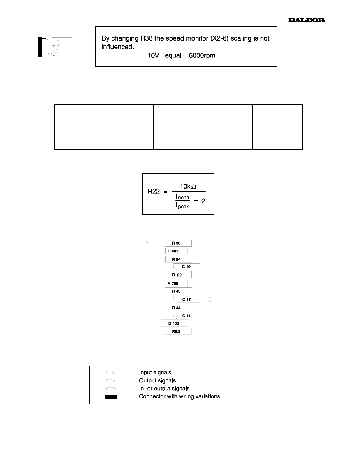
X2 - 6 Speed - Actual velocity of the motor
± 10V equal ± 6000rpm
X2 - 7 DCurrent Actual output current
0..+10V; 10V equal peak current
X2 - 8 Icmd Output of the velocity controller
± 10V equal peak current
9.0 Identity Modul (ID)
9.1 Component Functions
Components Function Value *)
R38 Scaling of Tacho (4000rpm) 4.99kΩ
D401 Plug-in protection -
R94 P-gain for velocity loop 100kΩ
C19 I-gain for velocity loop 47nF
R22 It-switching threshold (nom.current) -
R765 Special function 26.7kΩ
R43 P-gain for current loop phase U 150kΩ
C17 I-gain for current loop phase U 4.7nF
R44 P-gain for current loop phase V 150kΩ
C11 I-gain for current loop phase V 4.7nF
D402 Plug-in protection -
RES Reserved for special applications -
*) Standard values
-Scaling of tacho (R38):
0Ω for 6000rpm
4.99kΩ for 4000rpm
10.0kΩ for 3000rpm
20.0kΩ for 2000rpm
Applications over 6000rpm on request ex factory Munich.
Page 26
24
- It-switching threshold adjust:
With resistor R22 on the ID-card it is possible to adjust the It-switching threshold (It-Limit) from 0% upto 100%. Table
below shows nom. current to peak current by changing R22:
R22 BSC x015
I
= 30A
peak
- I
20kΩ
10kΩ
5kΩ
x: 2 or 3; e.g.: BSCx015 stands for BSC2015 and BSC3015
= 15,0A I
nenn
I
= 12,0A I
nenn
I
= 10,0A I
nenn
I
= 7,5A I
nenn
BSC x025
I
= 50A
peak
= 25,0A I
nenn
= 20,0A I
nenn
= 16,7A I
nenn
= 12,5A I
nenn
BSC x035
I
= 70A
peak
= 35,0A I
nenn
= 28,0A I
nenn
= 23,3A I
nenn
= 17,5A I
nenn
BSC 2045
I
= 90A
peak
= 45,0A
nenn
= 36,0A
nenn
= 30,0A
nenn
= 22,5A
nenn
Equation for R22:
9.2 Component Layout
10.0 I/O Hardware Description
- Legend:
Page 27

10.1 Input Signals
Analog Input Connector X2
Function Signal PIN Hardware
Velocity- or
Current-
Command
CMD+
CMD-
AGND
25
1
2
3
U
cmd
= ±10V
DC
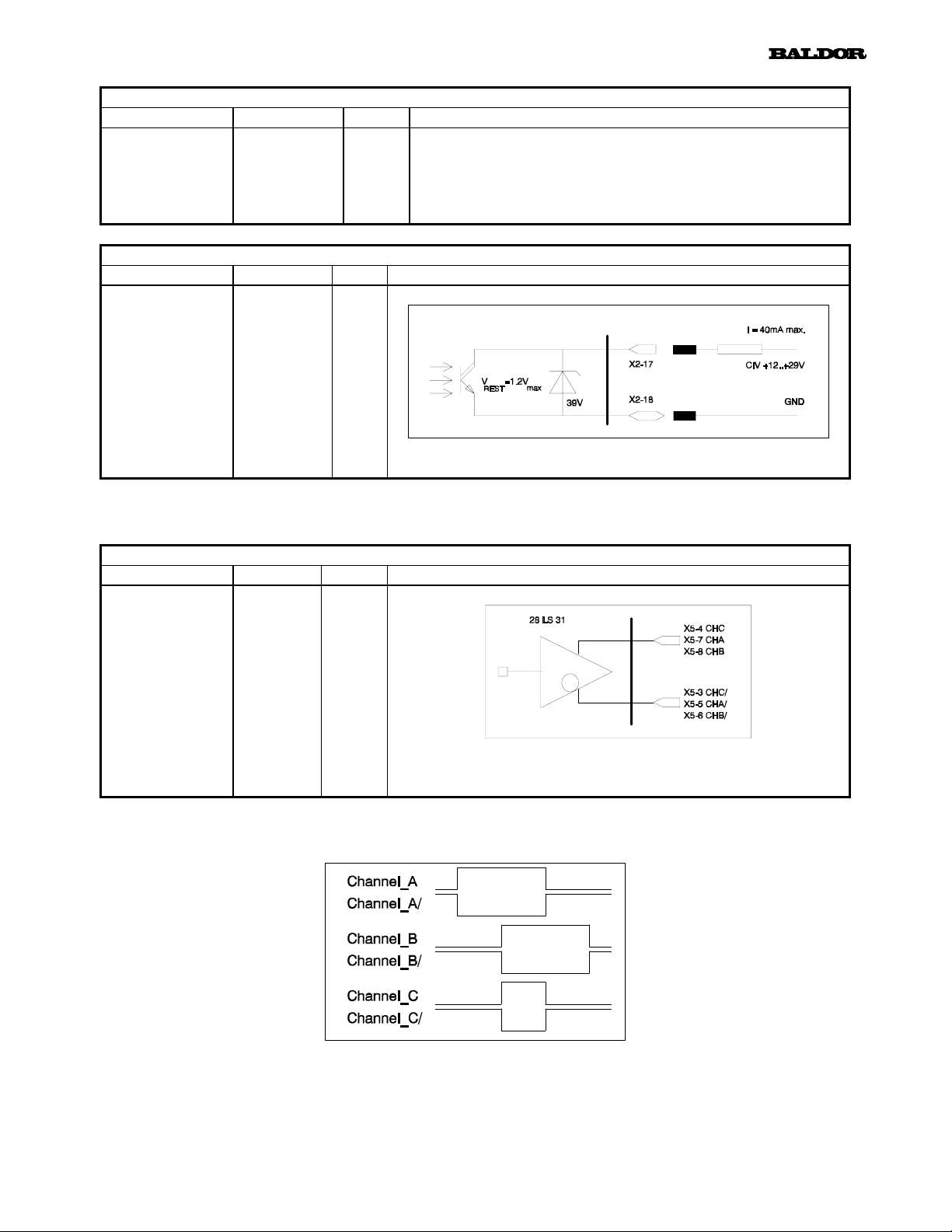
Digital Inputs Connector X2
Function Signal PIN Hardware
Enable
Emergency
Stop
CW-Limit
CCW-Limit
Current
Control
Ground Return
ENABLE
CWLimit
CCWLimit
CurrentC
EMStop
CREF
- Low Active:
9
10
11
- High Active:
12
13
14
min. Input Impedance R
opto coupled; U
max. current at 24V; I = 10mA
= 2.2kΩ;
IN
= 12 .. 29VDC; Delay time Td = 60μs
IN
Page 28

RESET - Input Connector X2
Function Signal PIN Hardware
RESET-
Input
Reset
DGND
19
20
26
10.2. Output signals
±15V - Output Connector X2
Function Signal PIN Hardware
±15VDC
Outputs
+15VDC
AGND
-15VDC
Pull-up to +5V; not opto coupled
Connect RESET to DGND, this resets the following faults:
- Overvoltage
- Undervoltage
- Resolver fault
- Electronic fusing
4
3
5
Digital Outputs Connector X2
Function Signal PIN Hardware
Fault
Relay
Fault+
Fault-
CAUTION: A short circuit will generate a "RESET"
Short circuit proof; I
15
16
contact is closed, if system works correct
U
U
AC
DC
= 110V I
= 24V I
max
max
= 0.3A
= 0.8A
= 100mA
max
Page 29
Analog Outputs Connector X2
Function Signal PIN Hardware
Testsignals
see
chapter 8
Digital Outputs Connector X2
Function Signal PIN Hardware
It - Warning
Speed-
DCurrent
Icmd
Warn_C
Warn_E
27
17
18
6
All testsignals are terminated with a resistor R = 4.7kΩ
7
and scaled to 10V
8
Load resistor R ≥ 100kΩ
10.3 Encoder Output
Encoder Signals Connector X5
Function Signal PIN Hardware
Encoder
Channel_C
Encoder
Channel_A
Encoder
Channel_B
CHC/
CHC
CHA/
CHA
CHB/
CHB
10.3.1 Encoder Signals
It-Limit and overtemperature warning
3
4
5
7
6
8
I/O-standard RS422
TTL-Signal; (f < 275kHz)
This drawing shows the encoder signals if the motor shaft rotates clock wise (view at the motor shaft).
Page 30
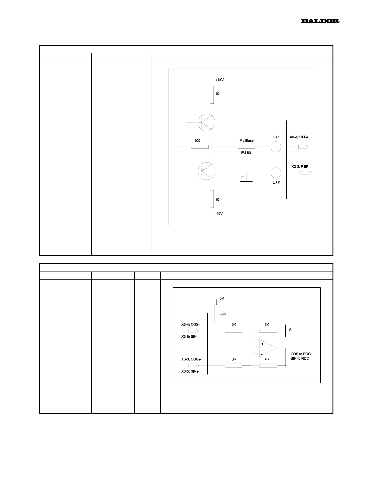
10.4 Resolver
Resolver Signals Connector X3
Function Signal PIN Hardware
Reference
Signal
REF+
REF-
28
1
2
Resolver Signals Connector X3
Function Signal PIN Hardware
COSINE
Input
SINE
Input
Cos+
Cos-
Sin+
Sin-
Signal waveform sinusoidal; f = 7.2 .. 8.0kHz;
17.0V
3
4
5
6
±5% + 0 .. 0.4 VDC; I
pp
Signal waveform sinusoidal;
UIN = 0 .. 10Vpp + 0 .. 0,4VDC; 7.2 .. 8.0kHz
= 0.2A; short circuit proof
peak
 Loading...