

Page 1
Baldor Electric Company, P. O. Box 2400, Ft. Smith, AR 72902-2400, (479) 646-4711, Fax (479) 648-5792
90 Volts DC
180 Volts DC
T
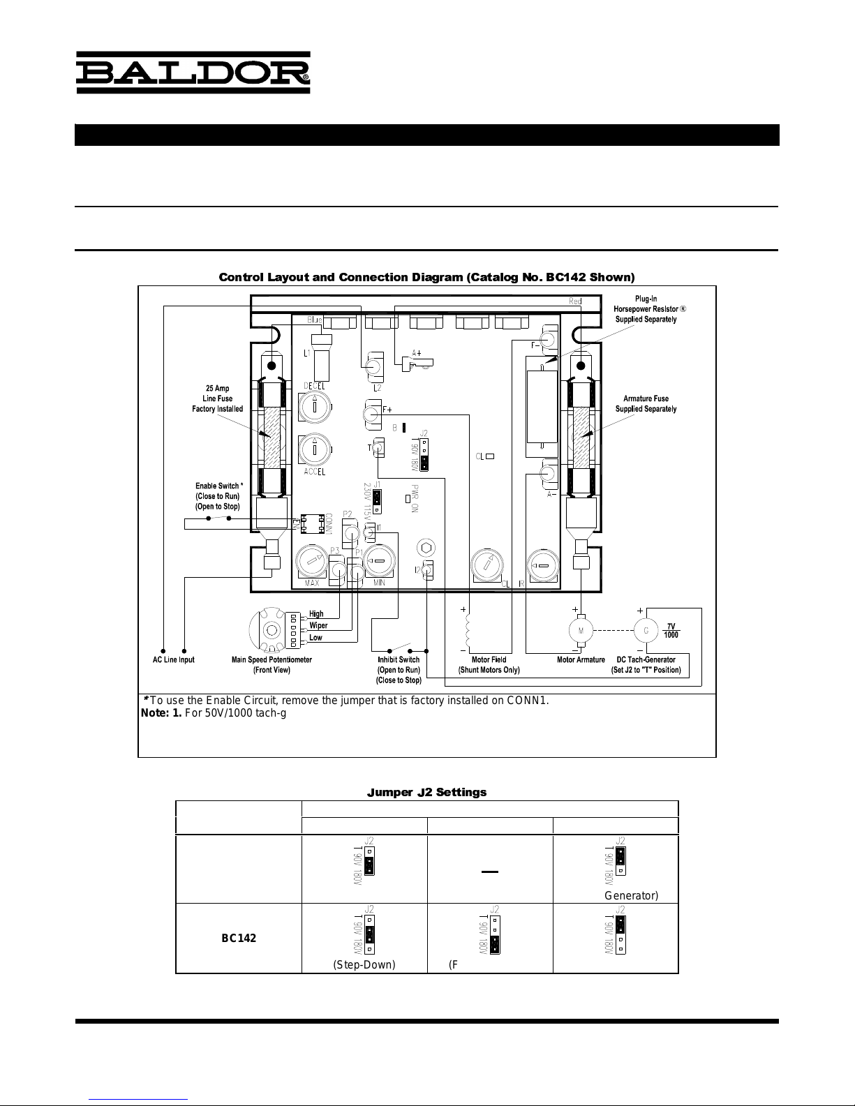
&DWDORJ1RV%&DQG%&6XSSOHPHQWDO,QIRUPDWLRQ
IMPORTANT: The following information and instructions are to be used as a supplement to the Installation and Operation
Manual (Part No. MN704). The manual must be read and understood before attempting to operate this control.
• The General Performance Specifications, Electrical Ratings, and Mechanical Specifications of these controls have not changed •
• Jumper J2 (DC Output Voltage / Tach Selection) and Enable Connector (EN) have been added •
• Diagnostic LEDs for Power On and Current Limit • Now with SMT Construction •
! "$#%&'%()*,+.-/01
2
To use the Enable Circuit, remove the jumper that is factory installed on CONN1.
Note: 1. For 50V/1000 tach-generator, connect to Terminals B (+) and I2 (-).
Application Note: When the control is stopped using Inhibit, the motor will coast to stop. When the control is
stopped using Enable, the motor will decelerate to stop. The deceleration time can only be made longer than the
normal coasting time of the load.
Catalog No.
BC141
BC142
Notes: 1. The 180V position, on Jumper J2, is not available on Catalog No. BC141. 2. The control
will run at full speed, if Jumper J2 is in the "T" position and the tach-generator is miswired.
Part No. MN704-SUP
(A42130) - Rev. A03 - 5/21/2004 - Z2993A03 Page 1 of 1
,43*,+567
3
Jumper J2 (DC Output Voltage / Tach Selection)
(Factory Setting) (Tach-Generator)
(Step-Down) (Factory Setting)
(Tach-Generator)
Page 2

DC DRIVE
BC141, BC142 & BC142-6 DC CONTROL
5/2004
MN704
Installation and Operation Manual
Page 3

TABLE OF CONTENTS
Section Page
1 Simplified Installation Instructions . . . . . . . . . . . . . . . . . . . . . . . . . . . . . . . . . . . . . . . . . . . . . . . . . . . . . . . . . . . . . 4
2 Safety Warning . . . . . . . . . . . . . . . . . . . . . . . . . . . . . . . . . . . . . . . . . . . . . . . . . . . . . . . . . . . . . . . . . . . . . . . . . . . 6
3 Introduction . . . . . . . . . . . . . . . . . . . . . . . . . . . . . . . . . . . . . . . . . . . . . . . . . . . . . . . . . . . . . . . . . . . . . . . . . . . . . . 7
4 Application Information . . . . . . . . . . . . . . . . . . . . . . . . . . . . . . . . . . . . . . . . . . . . . . . . . . . . . . . . . . . . . . . . . . . . 11
5 Mounting Instructions . . . . . . . . . . . . . . . . . . . . . . . . . . . . . . . . . . . . . . . . . . . . . . . . . . . . . . . . . . . . . . . . . . . . . 12
6 Wiring Instructions . . . . . . . . . . . . . . . . . . . . . . . . . . . . . . . . . . . . . . . . . . . . . . . . . . . . . . . . . . . . . . . . . . . . . . . 13
7 Setting Selectable Jumpers . . . . . . . . . . . . . . . . . . . . . . . . . . . . . . . . . . . . . . . . . . . . . . . . . . . . . . . . . . . . . . . . 19
8 AC Line Fusing . . . . . . . . . . . . . . . . . . . . . . . . . . . . . . . . . . . . . . . . . . . . . . . . . . . . . . . . . . . . . . . . . . . . . . . . . . 20
9 Plug-In Horsepower Resistor® and Armature Fuse Kit . . . . . . . . . . . . . . . . . . . . . . . . . . . . . . . . . . . . . . . . . . . . 21
10 Recommended High Voltage Dielectric Withstand Testing (Hi-Pot Testing) . . . . . . . . . . . . . . . . . . . . . . . . . . . . . 22
11 Trimpot Adjustments . . . . . . . . . . . . . . . . . . . . . . . . . . . . . . . . . . . . . . . . . . . . . . . . . . . . . . . . . . . . . . . . . . . . . . 24
12 Diagnostic LEDs . . . . . . . . . . . . . . . . . . . . . . . . . . . . . . . . . . . . . . . . . . . . . . . . . . . . . . . . . . . . . . . . . . . . . . . . . 28
13 Switching Circuits . . . . . . . . . . . . . . . . . . . . . . . . . . . . . . . . . . . . . . . . . . . . . . . . . . . . . . . . . . . . . . . . . . . . . . . . 28
14 Optional Accessories . . . . . . . . . . . . . . . . . . . . . . . . . . . . . . . . . . . . . . . . . . . . . . . . . . . . . . . . . . . . . . . . . . . . . 30
Limited Warranty . . . . . . . . . . . . . . . . . . . . . . . . . . . . . . . . . . . . . . . . . . . . . . . . . . . . . . . . . . . . . . . . . . . . . . . . . . . . 32
Tables
1 Electrical Ratings . . . . . . . . . . . . . . . . . . . . . . . . . . . . . . . . . . . . . . . . . . . . . . . . . . . . . . . . . . . . . . . . . . . . . . . . . 9
2 General Performance Specifications . . . . . . . . . . . . . . . . . . . . . . . . . . . . . . . . . . . . . . . . . . . . . . . . . . . . . . . . . . . 9
3 Minimum Supply Wire Size Requirements . . . . . . . . . . . . . . . . . . . . . . . . . . . . . . . . . . . . . . . . . . . . . . . . . . . . . . 13
4 Field Connection (Shunt Wound Motors Only) . . . . . . . . . . . . . . . . . . . . . . . . . . . . . . . . . . . . . . . . . . . . . . . . . . . 14
5 Plug-In Horsepower Resistor® and Armature Fuse Kit Selection . . . . . . . . . . . . . . . . . . . . . . . . . . . . . . . . . . . . 22
Figures
1 Control Layout and General Connection Diagram . . . . . . . . . . . . . . . . . . . . . . . . . . . . . . . . . . . . . . . . . . . . . . . . 10
2 Mechanical Specifications . . . . . . . . . . . . . . . . . . . . . . . . . . . . . . . . . . . . . . . . . . . . . . . . . . . . . . . . . . . . . . . . . . 11
3 Remote Main Speed Potentiometer Connection . . . . . . . . . . . . . . . . . . . . . . . . . . . . . . . . . . . . . . . . . . . . . . . . . 15
2
Page 4

TABLE OF CONTENTS (Continued)
Figures Page
4 Voltage Following Connection . . . . . . . . . . . . . . . . . . . . . . . . . . . . . . . . . . . . . . . . . . . . . . . . . . . . . . . . . . . . . . . 15
5 Enable Switch or Contact Wired to the Enable Connector . . . . . . . . . . . . . . . . . . . . . . . . . . . . . . . . . . . . . . . . . 16
6 Enable Switch or Contact Wired to the Main Speed Potentiometer . . . . . . . . . . . . . . . . . . . . . . . . . . . . . . . . . . 17
7 Inhibit Switch or Contact Wired to the Inhibit Terminals . . . . . . . . . . . . . . . . . . . . . . . . . . . . . . . . . . . . . . . . . . . . 17
8 DC Tach-Generator Connection (7 Volts per 1000 RPM) . . . . . . . . . . . . . . . . . . . . . . . . . . . . . . . . . . . . . . . . . . 18
9 DC Tach-Generator Connection (50 Volts per 1000 RPM) . . . . . . . . . . . . . . . . . . . . . . . . . . . . . . . . . . . . . . . . . 18
10 Other DC Tach-Generator Connection (with Addition of RT) . . . . . . . . . . . . . . . . . . . . . . . . . . . . . . . . . . . . . . . . 19
11 AC Line Input Voltage Selection (Jumper J1 (Catalog No. BC142-6 Only)) . . . . . . . . . . . . . . . . . . . . . . . . . . . . . 20
12 Motor Voltage and DC Tach-Generator Selection (Jumper J2) . . . . . . . . . . . . . . . . . . . . . . . . . . . . . . . . . . . . . . 20
13 Hi-Pot Test Setup . . . . . . . . . . . . . . . . . . . . . . . . . . . . . . . . . . . . . . . . . . . . . . . . . . . . . . . . . . . . . . . . . . . . . . . . 23
14 Acceleration Trimpot (ACCEL) Range . . . . . . . . . . . . . . . . . . . . . . . . . . . . . . . . . . . . . . . . . . . . . . . . . . . . . . . . . 24
15 Deceleration Trimpot (DECEL) Range . . . . . . . . . . . . . . . . . . . . . . . . . . . . . . . . . . . . . . . . . . . . . . . . . . . . . . . . . 25
16 Minimum Speed Trimpot (MIIN) Range . . . . . . . . . . . . . . . . . . . . . . . . . . . . . . . . . . . . . . . . . . . . . . . . . . . . . . . . 25
17 Maximum Speed Trimpot (MAX) Range . . . . . . . . . . . . . . . . . . . . . . . . . . . . . . . . . . . . . . . . . . . . . . . . . . . . . . . . 25
18 Current Limit Trimpot (CL) Range . . . . . . . . . . . . . . . . . . . . . . . . . . . . . . . . . . . . . . . . . . . . . . . . . . . . . . . . . . . . 26
19 IR Compensation Trimpot (IR) Range . . . . . . . . . . . . . . . . . . . . . . . . . . . . . . . . . . . . . . . . . . . . . . . . . . . . . . . . . 27
20 Typical Dynamic Brake Circuit Connection . . . . . . . . . . . . . . . . . . . . . . . . . . . . . . . . . . . . . . . . . . . . . . . . . . . . . 29
Items Included in this package – Speed Control, factory installed 25 Amp AC Line Fuse, Installation and Operation
Manual, Hardware Bag (contains Main Speed Potentiometer with insulator and mounting hardware, (9) – 0.25” female
crimp-on terminals, (4) – 0.11” female crimp-on terminals, and an Enable harness), CE Approved Product Information
Card, and Warranty Registration Card.
Items required to operate this control – Plug-In Horsepower Resistor® and Armature Fuse Kit. Supplied through
your distributor. See Section 9, on page 21.
3
Page 5

Note: A Plug-In Horsepower Resistor® and Armature Fuse
Kit must be installed in order for this product to operate.
See Section 9, on page 21.
1 SIMPLIFIED INSTALLATION INSTRUCTIONS
4
1.1 AC Line Connection – Wire the AC line to Terminals “L1” (Line Fuse) and “L2”, as shown in Figure 1, on
page 10 and as described in Section 6.1, on page 13.
Catalog No. BC141 is rated for 115 Volt AC line input only. Catalog No. BC142 is rated for 230 Volt AC line
input only. Catalog No. BC142-6 is rated for 115 Volt AC line input (Jumper J1 in the “115V” position) and
230 Volt AC line input (Jumper J1 in the “230V” position). See Section 7.1, on page 19.
Notes: 1. The rated AC line voltage (115, 208/230) of the control must match the actual AC line input
voltage. 2. If one of the AC line inputs is a neutral (N), wire it to Terminal “L2”.
1.2 Ground Connection – Connect the ground wire (earth) to the control chassis.
1.3 Motor Connection – Connect the motor to Terminals “A+” (Armature Fuse) and “A-”, as shown in Figure 1,
on page 10, and as described in Section 6.3, on page 14.
1.4 Jumper Settings – Jumper J1 (on Catalog No. BC142-6 only) and Jumper J2 (all models) have been facto-
ry set for most applications, as shown in Figure 1, on page 10, and as described in Section 7, on page 19.
IMPORTANT – Read these simplified installation instructions before proceeding. These instructions are to be
used as a reference only and are not intended to replace the detailed instructions provided herein. You must
read the Safety Warning, on page 6, before proceeding.
Fuse
Plug-In Horsepower
Resitor®
Page 6

1.5 AC line Fusing – A 25 Amp AC line fuse is factory installed in the AC Line Fuse Holder, as shown in Figure
1, on page 10. It is recommended that this fuse be changed to a 12 Amp fuse for motors rated 7.5 Amps
DC or less. Fuse each conductor that is not at ground potential.
1.6 Plug-In Horsepower Resistor® and Armature Fuse – It is required that a Plug-In Horsepower Resistor®
and Armature Fuse be installed. These are supplied separately in a kit which is based on motor horsepower
and voltage. Select the correct kit as described in Section 9, on page 21.
1.7 Trimpot Settings – All trimpots have been factory set for most applications, as shown in Figure 1, on page
10. The trimpots may be readjusted, as described in Section 11, on page 24.
1.8 Diagnostic LEDs – After power has been applied to the control, observe the LEDs to verify proper control
operation, as described in Section 12, on page 28.
1.9 Auxiliary Heat Sink (Catalog No. BC143) – Extends the horsepower rating of the control to 1.5 HP for
controls with 90 Volt DC output and 3 HP for controls with 180 Volt DC output.
5
Page 7
6
This product should be installed and serviced by a qualified technician, electrician, or electrical main-
tenance person familiar with its operation and the hazards involved. Proper installation, which includes
wiring, mounting in proper enclosure, fusing or other over current protection, and grounding can reduce the
chance of electrical shocks, fires, or explosion in this product or products used with this product, such as electric motors, switches, coils, solenoids, and/or relays. Eye protection must be worn and insulated adjustment tools
must be used when working with control under power. This product is constructed of materials (plastics, metals,
carbon, silicon, etc.) which may be a potential hazard. Proper shielding, grounding, and filtering of this product
can reduce the emission of radio frequency interference (RFI) which may adversely affect sensitive electronic
equipment. It is the responsibility of the equipment manufacturer and individual installer to supply this Safety
Warning to the ultimate end user of this product. (SW effective 11/1992). Be sure to follow all instructions carefully. Fire and/or electrocution can result due to improper use of this product.
!
Definition of Safety Warning Symbols:
Electrical Hazard Warning Symbol – Failure to observe this warning could result in electrical shock
or electrocution.
Operational Hazard Warning Symbol – Failure to observe this warning could result in serious injury
or death.
2 SAFETY WARNING – Please read carefully.
!
This product complies with all CE directives pertinent at the time of manufacture. Installation of a CE
approved RFI filter is required (see Section 14.8, on page 30). Additional shielded cable and/or AC
line cables may be required along with a signal isolator (Catalog No. BC152).
Page 8

3 INTRODUCTION
Thank you for purchasing the BC141, BC142, or BC142-6 full-wave variable speed DC motor control, now with
SMT construction. The control offers the user the ultimate in reliability and performance at an affordable price. The
controls contain a unique patented super-fast Direct-Fed™ current limit circuit that protects the SCR power
bridge against direct shorts
1
. The reliability of the control is further enhanced with the use of high-surge, 25 Amp
SCRs, and AC line and armature fusing
2, 3
. The control is designed with exclusive Plug-In Horsepower
Resistor®
3
, which eliminates the need for recalibrating IR Comp and Current Limit when the control is used on
various horsepower motors. In addition, the rating of the control can be extended to 1.5 HP for controls with 90
Volt DC output and 3 HP for controls with 180 Volt DC output, by the use of an Auxiliary Heat Sink
4
. Catalog Nos.
BC142 and BC142-6 also allow operation of 90 Volt DC motors when used on 208/230 Volt AC line input
5
.
The versatility of the control is confirmed by its extensive list of standard features, such as: selectable armature
and tach feedback and adjustment trimpots for minimum speed, maximum speed, IR compensation, and linear
acceleration and deceleration. The control includes Auto-Inhibit®, which eliminates surging during rapid AC line
switching; pulse transformer triggering, which provides cogless operation at low speed; and superior noise rejection circuitry, which eliminates false starts and blown SCRs. Enable (normally closed) and Inhibit (normally open)
functions provide electronic switching of control output.
The output voltage of the control is a linear function of the Main Speed Potentiometer rotation. In addition, the
control can be used in a voltage following mode by supplying an isolated analog input signal to Terminals “P2” (+)
and “P1” (-). The control is compact in size (only 4.30” X 3.64” X 1.25”) and easily replaces all competitive speed
controls. The control is supplied with a factory installed 25 Amp AC line fuse and a 5 k Ω Main Speed
Potentiometer and QD terminals. All models are UL Listed (USA and Canada) and CE Approved.
Notes: 1. Short circuit protected at motor only. 2. Baldor Limited Warranty applies. See page 32. 3. Plug-In
Horsepower Resistor® and Armature Fuse Kit supplied separately. See Sections 8 and 9, on pages
20 - 22. 4. Catalog No. BC143. See Section 14.1, on page 30. 5. Step-Down operation.
7
Page 9

3.1 Standard Features
1 Plug-In Horsepower Resistor® – Eliminates the need to calibrate the control for IR Compensation
and Current Limit when used on various horsepower motors.
2 Auto-Inhibit® – Allows the control to be rapidly switched “on” and “off” using the AC line.
3 Inhibit and Enable – Allows the control to be turned “on” and “off” using electronic switching.
4 Trimpots – Minimum Speed (MIN), Maximum Speed (MAX), IR Compensation (IR), Current Limit (CL),
Acceleration (ACCEL), and Deceleration (DECEL).
5 Jumpers – AC Line Input Voltage Selection (J1 (Catalog No. BC142-6 only)), Motor Voltage and DC
Tach-Generator Selection (J2).
6 Protection Features – MOV transient protection. Short Circuit protected (at motor only).
7 Diagnostic LEDs – Power On (PWR ON) and Current Limit (CL).
8 Catalog No. BC141 operates on 115 Volt AC line input with 90 Volt DC motors.
9 Catalog No. BC142 operates on 230 Volt AC line input with 180 Volt DC motors or 90 Volt DC motors
(step-down). - Jumper Selectable.
10 Catalog No. BC142-6 can operate on 115 Volt AC line input with 90 Volt DC motors and 230 Volt AC
line input with 180 Volt DC motors or 90 Volt DC motors (step-down). - Jumper selectable.
11 Armature or DC Tach-Generator feedback.
12 SMT construction.
8
Page 10

Notes: 1. Step-down operation: motor may have reduced brush life. 2. Performance is for SCR rated permanent magnet motors only. Lower performance can be
expected with other motor types. Factory setting is for 3% load regulation. To obtain superior regulation, see Section 11.6, on page 27.
9
Catalog
Number
AC Line
Voltage
(±15%, 50/60Hz)
(Volts AC)
Motor
Voltage
(Volts DC)
Rating without Auxiliary Heat Sink Rating with Auxiliary Heat Sink
Field Voltage
(Volts DC)
Maximum AC
Line Current
(RMS Amps)
Maximum DC
Load Current
(Avg. Amps)
Maximum
Horsepower
(HP (kw))
Maximum AC
Line Current
(RMS Amps)
Maximum DC
Load Current
(Avg. Amps)
Maximum
Horsepower
(HP (kw))
BC141 115 0 - 90 12.0 8.0 .75 (.6) 24.0 16.0 1.5 (1.1) 50, 100
BC142 230
0 - 180 12.0 8.0 1.5 (1.1) 24.0 16.0 3 (2.3) 100, 200
0 - 90* 12.0 8.0 .75 (.6) 24.0 16.0 1.5 (1.1) 100
BC142-6
115 0 - 90 12.0 8.0 .75 (.6) 24.0 16.0 1.5 (1.1) 50, 100
230
0 - 180 12.0 8.0 1.5 (1.1) 24.0 16.0 3 (2.3) 100, 200
0 - 90* 12.0 8.0 .75 (.6) 24.0 16.0 1.5 (1.1) 100
TABLE 1 – ELECTRICAL RATINGS
TABLE 2 – GENERAL PERFORMANCE SPECIFICATIONS
* Step-down operation.
Description Specification Factory Setting
Speed Range (Ratio) 50:1 —
Armature Feedback Load Regulation (0 - Full Load, 50:1 Speed Range) (% Base Speed) 1 —
Tach-Generator Feedback Load Regulation (0 - Full Load, 50:1 Speed Range) (% Set Speed) 1 —
Line Voltage Regulation (at Full Load, ± 10% Line Variation) (% Speed) 0.5 —
Control Linearity (% Speed vs. Dial Rotation) 2 —
Acceleration (ACCEL) Trimpot Range (Seconds) 0.2 – 10 2
Deceleration (DECEL) Trimpot Range (Seconds) 0.2 – 10 2
Maximum Speed (MAX) Trimpot Range (% Base Speed) 50 – 110 100
Minimum Speed (MIN) Trimpot Range (% Base Speed) 0 – 30 0
Current Limit (CL) Trimpot Range (% Full Load) 0 – 200 150
IR Compensation (IR) Trimpot Range (at Specified Full Load @ 90, 180 Volts DC Output) (Volts DC) 0 – 24, 48 3, 6
Page 11

J1
Motor ArmatureMotor Field
(Shunt Motors Only)
DC Tach-Generator
(Set J2 to "T" Position)
Main Speed PotentiometerAC Line
Input
(Front View)
Inhibit Switch
(Close to Stop)
(Open to Run)
Enable Switch
(Open to Stop)
(Close to Run)
Line Fuse
25 Amp
Factory Installed Supplied Separately
Armature Fuse
Wiper
Low
High
Horsepower Resistor®
Supplied Separately
Plug-In
L1
Blue
A+
F-
Red
ACCEL
DECEL
EN
-
+
M
-
+
CONN1
P2
G
-
+
1000
7V
PWR ON
230V 115V
I1
T
B
F+
A-
T 90V 180V
J2
CL
L2
P3
MAX
P1
MIN
I2
IR
CL
Plug-In Horsepower
Resistor® and
Armature Fuse Kit
supplied separately
See Section 9,
on page 21.
10
FIGURE 1 – CONTROL LAYOUT & GENERAL CONNECTION DIAGRAM (Catalog No. BC142-6 Shown)
Page 12

CONTROL
MOUNTING "D"
2 SLOTS
POTENTIOMETER
(SUPPLIED)
MAIN SPEED
OPTIONAL AUXILIARY HEAT SINK
.95
24.1
1.25
31.8
.50
12.7
.98
24.9
5.63
142.9
3.11
(79.0)
5.63
142.9
6.25
158.8
1.25
31.8
1.38
34.9
7.00
177.8
1
ANTIROTATION
PIN
3/8-32
BUSHING
3/8"
SHAFT
1/4" ROUND
1/2"
P
2
P
3
P
.44
11.1
.13
3.1
MOUNTING "B"
TAPPED 10-32
(3 PLACES)
FUSE & FINGER-SAFE
COVER MOUNTING HOLES
TAPPED 6-32
(2 PLACES)
MOUNTING "A"
6 SLOTS
3.64
92.5
3.10
78.5
.22
5.6
4.30
109.2
2.15
54.6
.25
6.4
.18
4.6
.64
16.3
1.75
44.5
1.75
44.5
.75
19.1
1.50
38.1
3.00
76.2
11
4 APPLICATION INFORMATION
4.1 Motor Type – The control is designed for permanent magnet (PM) and Shunt Wound DC motors. Controls
operated on 115 Volt AC line input are designed for 90 Volt SCR rated motors. Controls operated on 230
Volt AC line input are designed for 180 and 90 Volt SCR rated motors. Use of higher voltage motors will
result in a reduction of the available maximum speed. Also, if the motor is not an SCR rated type, the actual
AC line current at full load should not exceed the motor’s DC nameplate current rating.
4.2 Torque Requirements – The motor selected for the application must be capable of supplying the necessary
torque. In order to ensure the motor is not overloaded, a DC ammeter should be connected in series with
the armature. Be sure the current under full load does not exceed the motor nameplate rating.
FIGURE 2 – MECHANICAL SPECIFICATIONS (Inches/mm)
Page 13

4.3 Acceleration Start – The control contains an adjustable acceleration start feature which allows the motor to
smoothly accelerate from zero speed to full speed over a time period of 0.2 - 10 seconds. The acceleration
trimpot (ACCEL) is factory set for 2 seconds.
4.4 Limitation In Use – The controls are designed for use on machine applications.
4.5 Armature Switching – Do not wire the control for armature switching without taking proper precautions.
See Section 13.2, on page 29.
WARNING! Do not switch the armature in and out of circuit or catastrophic failure will result. If armature switching is required for reversing or dynamic braking, use Catalog Nos. BC204, BC200, or BC201.
4.6 Step-Down Transformer and AC Line Switching – When using a step-down transformer (460 Volts AC to
230 Volts AC), be sure the output current rating of the transformer is at least 3 times the current rating of the
motor. Do not switch the primary side of the transformer to disconnect power or catastrophic failure can
result. Always disconnect the control from the secondary side of the transformer.
CAUTION! Do not use this control in an explosive atmosphere. Be sure the control is used within its
ratings. Follow all instructions carefully.
5 MOUNTING INSTRUCTIONS
It is recommended that the control be mounted on a flat surface with adequate ventilation. Leave enough room to
allow for AC line, motor connection, and other wiring that is required. Care should be taken to avoid extreme hazardous locations where physical damage can occur. When mounting the control in an enclosure, the enclosure
should be large enough to allow for proper heat dissipation so that the ambient temperature does not exceed
45 °C (113 °F). See Figure 2, on page 11.
12
!
!
Page 14

6 WIRING INSTRUCTIONS
WARNING! Read Safety Warning, on page 6, before using this control. Disconnect the main power
when making connections to the control.
Important Application Note: To avoid erratic operation, do not bundle the AC line and motor wires with
wires from signal following, start/stop contacts, or any other signal wires. Also, do not bundle motor
wires from multiple controls in the same conduit. Use shielded cables on all signal wiring over 12” (30
cm). The shield should be earth grounded on the control side only. Wire the control in accordance with
the National Electrical Code requirements and other local codes that may apply.
13
!
6.1 AC Line Connection – Wire the AC line to Terminals “L1” (Line Fuse) and “L2”, as shown in Figure 1, on
page 10. If one of the AC line inputs is a neutral (N), wire it to Terminal “L2”.
CAUTION! The rated AC line voltage (115, 208/230) of the control must match the actual AC line
input voltage. See Section 7.1, on page 19.
Catalog No. BC141 operates on 115 Volt AC line input only. Catalog No. BC142 operates on 208/230 Volt
AC line input only. Catalog BC142-6 operates on 115 Volt AC line input when Jumper J1 is set to the “115”
position and operates on 208/230 Volt AC line input when Jumper J1 is set to the “230V” position (factory
setting).
Maximum Motor Current
(Amps DC)
90 - 130 Volt DC Motors
(Maximum HP)
180 Volt DC Motors
(Maximum HP)
Minimum Wire Size (Cu)
Maximum 50 Ft. Maximum 100 Ft.
AWG
mm
2
AWG
mm
2
6 .5 1 16 1.3 14 2.1
12 1 2 14 2.1 12* 3.3*
16 1.5 3 12* 3.3* 12* 3.3*
TABLE 3 – MINIMUM SUPPLY WIRE SIZE REQUIREMENTS
* Maximum recommended wire size.
!
Page 15

6.2 Ground Connection – Connect the ground wire (earth) to the control chassis.
6.3 Permanent Magnet (PM) Motor Connection – Wire the motor armature positive lead (+) to Terminal “A+”
(Armature Fuse) and the negative lead (-) to Terminal “A-”, as shown in Figure 1, on page 10. On Catalog
Nos. BC142 and BC142-6, be sure Jumper J2 is set to the corresponding motor voltage, as described in
Section 7.2, on page 20. Be sure the correct Plug-In Horsepower Resistor® is installed, as described in
Section 9, on page 21.
6.4 Motor Field Connection (Shunt Wound Motors Only)
6.4.1 Full Voltage Field – Wire the field positive (+) lead to Terminal “F+” and the negative lead (-) to
Terminal “F-”, as shown in Figure 1, on page 10, and as described in Table 4.
6.4.2 Half Voltage Field – For 90 Volt DC motors with 50 Volt DC fields and 180 Volt DC motors with 100
Volt DC fields, wire the field positive lead (+) to Terminal “F+” and the negative lead (-) to Terminal “L1”
(Line Fuse), as described in Table 4.
Notes: 1. Do not connect motor armature leads to Terminals “F+” and “F-”. 2. Do not use Terminals “F+”
and “F-” for any purpose other than to power the field of a shunt wound motor. 3. Shunt wound motors
may be damaged if the field remains energized without armature rotation for an extended period of time.
14
Catalog No. AC Line Input Voltage (Volts AC) Armature Voltage (Volts DC) Field Voltage (Volts DC) Terminal Connections
BC141 115 0 - 90
100 F+, F-
50 F+, L1
BC142 208 / 230
0 - 180 200 F+, F-
0 - 90* 100 F+, L1
BC142-6
115 0 - 90
100 F+, F-
50 F+, L1
208 / 230 0 - 180 200 F+, F-
208 / 230 0 - 90* 100 F+, L1
TABLE 4 – FIELD CONNECTION (Shunt Wound Motors Only)
* Step-down operation.
Page 16

6.5 Remote Main Speed Potentiometer Connection – The control
is supplied with a Main Speed Potentiometer to control motor
speed. Wire the low side of the potentiometer to Terminal “P1”.
Wire the wiper of the potentiometer to Terminal “P2”. Wire the
high side of the potentiometer to Terminal “P3”. See Figure 3.
6.6 Voltage Following Connection – An isolated 0 - 9 Volt DC ana-
log signal input can be used to control motor speed in lieu of the
Main Speed Potentiometer. The control output voltage will linearly
follow the analog signal input. The signal input must be isolat-
ed from the AC line. Connect the signal input positive lead (+) to
Terminal “P2” and the negative lead (-) to Terminal “P1”, as
shown in Figure 4. The source impedance of the signal input
should be 10 kΩ or less. The MAX Trimpot is not operational in
voltage following mode. Turn the MIN Trimpot, on the control, to
zero output (full counterclockwise rotation) and use auxiliary trimpots, if necessary, to scale and/or limit the input voltage.
CAUTION! Do not earth ground any input terminals.
Notes: 1. If an isolated signal input is not available, or if using a
4 - 20 mA DC signal input, install the optional plug-on Catalog
No. BC152 Signal Isolator. This will also allow direct connections
to process controllers and microprocessors. 2. If multiple follower
motors are to be controlled from a single leader motor or a single
Main Speed Potentiometer, install the optional Catalog No.
BC145 Signal Isolator. 3. Terminal “F-” may be used in lieu of Terminal “P1”.
15
(Front View)
Main Speed Potentiometer
EN
CONN1
P3
MAX
P1
P2
High
Wiper
Low
Terminal "P3"
Terminal "P1"
Terminal "P2"
FIGURE 3 – REMOTE MAIN SPEED
POTENTIOMETER CONNECTION
CONN1
P2
MAX
EN
P3
P1
V
-
+
0 - 9 Volts DC
(Isolated)
Terminal "P1"
Terminal "P2"
FIGURE 4 – VOLTAGE FOLLOWING
CONNECTION
!
Page 17

6.7 Enable Circuit Connection – The control can be started and stopped with an Enable Circuit (close to run),
as described below.
WARNING! The Enable Circuit is never to be used as a Safety Disconnect since it is not
fail-safe. Use only the AC line for this purpose.
6.7.1 Enable Switch or Contact Wired to the Enable Connector – Using the wired mating connector that
is supplied with the control, wire the switch or contact to the Enable connector (CONN1), as shown in
Figure 5. When the switch or contact is closed, the motor will accelerate to the Main Speed
Potentiometer setting. When the switch or contact is opened, the motor will decelerate to stop. An
open collector (PNP) can be wired in lieu of a switch or contact.
Notes: 1. To use
the Enable Circuit,
remove the jumper
that is factory
installed on
CONN1. 2. The
deceleration time
can only be made
longer than the
normal coasting
time of the load.
6.7.2 Enable Switch or Contact Wired to the Main Speed Potentiometer – Wire the switch or contact in
series with the Main Speed Potentiometer high side and Terminal “P3” on the control, as shown in
Figure 6, on page 17. Be sure the jumper is installed on the Enable Connector (CONN1). When the
switch or contact is closed, the motor will accelerate to the Main Speed Potentiometer setting. When
the switch or contact is opened, the motor will decelerate to the MIN Trimpot setting (factory set to 0
16
!
(On to Run)
(Off to Stop)
Open Collector
CONN1
MAX
EN
(Open to Stop)
(Close to Run)
or Contact
Enable Switch
the Mating Connector
CONN1
MAX
EN
Remove this jumper to install
CONN1
MAX
EN
FIGURE 5 – ENABLE SWITCH OR CONTACT WIRED TO THE ENABLE CONNECTOR
Page 18

Volts DC). If the MIN
Trimpot is set to other
than 0 Volts DC, the
motor will run at that
speed when the
switch or contact is
opened. An open collector (PNP) can be
wired in lieu of a
switch or contact.
Note: The deceleration time can only be
made longer than the
normal coasting time
of the load.
6.8 Inhibit Circuit Connection – The control can be stopped
and started with an Inhibit circuit (close to stop). Wire the
switch or contact to Terminals “I1” and “I2”, as shown in
Figure 7. When the switch or contact is closed, the motor will
coast to stop. When the switch or contact is opened, the
motor will accelerate to the Main Speed Potentiometer setting. An open collector (NPN) can be wired in lieu of a switch
or contact.
WARNING! The Inhibit Circuit is never to be used
as a Safety Disconnect since it is not fail-safe. Use
only the AC line for this purpose.
17
CONN1
Enable Switch or Contact
This jumper must
Main Speed Potentiometer
(Front View)
(Close to Run)
Low
High
Wiper
(Open to Stop)
be installed
MAX
EN
Terminal "P1"
Main Speed Potentiometer
(Front View)
(On to Run)
Low
High
Wiper
Open Collector
(Off to Stop)
MAX
CONN1
Terminal "P3"
Terminal "P2"
P3
P1
P2
EN
P3
P1
P2
FIGURE 6 – ENABLE SWITCH OR CONTACT WIRED TO THE
MAIN SPEED POTENTIOMETER
!
MIN
I1
I2
(Close to Stop)
Inhibit Switch or Contact
(Open to Run)
MIN
I2
I1
(On to Stop)
(Off to Run)
Open Collector
Terminal "I1"
Terminal "I2"
FIGURE 7 – INHIBIT SWITCH OR CONTACT
WIRED TO THE INHIBIT TERMINALS
Page 19

6.9 DC Tach-Generator Connection – A DC tach-generator
can be used for load regulation of 1% of the set speed.
Note: Jumper J2 must be set to the “T” position for
tach-generator operation. Connect the tach-generator
as follows.
Application Notes – 1. The tach-generator input circuit is
designed for a 7 Volt or 50 Volt per 1000 RPM DC tachgenerator used with an 1800 RPM motor. 2. Initially set the
IR Comp Trimpot fully counterclockwise. Once the tachgenerator is connected, the IR Comp Trimpot may be
increased for additional speed stabilization.
6.9.1 Seven (7) Volt per 1000 RPM Tach-Generator –
Connect the tach-generator positive lead (+) to
Terminal “T” and the negative lead (-) to Terminal
“I2”, as shown in Figure 8.
6.9.2 Fifty (50) Volt per 1000 RPM Tach-Generator –
Connect the tach-generator positive lead (+) to
Terminal “B” and the negative lead (-) to Terminal
“I2”, as shown in Figure 9.
6.9.3 Other Tach-Generator Voltages – The tach-gener-
ator input circuit is designed for a 7 Volt or 50 Volt
per 1000 RPM DC tach-generator used with an
1800 RPM motor. For a tach-generator other than 7
Volts or 50 Volts per 1000 RPM, or for a motor
other than 1800 RPM, an external 1/2 Watt resistor
(RT) must be installed. Install RT in series with the
18
B
PWR ON
I2
T 90V 180V
T
J2
DC Tach-Generator
-
+
7V
G
1000
Terminal "T"
Terminal "I2"
FIGURE 8 – DC TACH-GENERATOR CONNECTION
(7 VOLTS PER 1000 RPM)
B
J2
PWR ON
I2
T 90V 180V
T
1000
G
50V
DC Tach-Generator
-
+
Terminal "B"
FIGURE 9 – DC TACH-GENERATOR CONNECTION
(50 VOLTS PER 1000 RPM)
Page 20

tach-generator. Connect one end of RT to Terminal
“T”, connect the other end of RT to the tachgenerator positive lead (+), and connect the negative
lead (-) of the tach-generator to Terminal “I2”. See
Figure 10.
The value of RT (Ω) can be calculated using the following formula: RT = (1.3 X VT X S) - 16000 Ω
Where “VT” is the tach-generator voltage (in Volts
per 1000 RPM) and “S” is the base speed of the
motor (in RPM).
Example: If a 20 Volt per 1000 RPM tach-generator
is to be used with a 3600 RPM motor:
RT = (1.3 X 20 X 3600) - 16000 = 77600 Ω
Choose the closest 1/2 Watt resistor value, which is 75000 Ω (75 kΩ).
7 SETTING SELECTABLE JUMPERS
The control has selectable jumpers which must be set before it can be used. See Figure 1, on page 10, for the
location of jumpers.
7.1 AC Line Input Voltage Selection (Jumper J1 (Catalog No. BC142-6 Only)) – Jumper J1 is factory set to
the “230V” position for 208/230 Volt AC line input. For 115 Volt AC line input, set Jumper J1 to the “115V”
position. See Figure 11, on page 20.
Notes: 1. Jumper J1 is installed on Catalog No. BC142-6 only. 2. When Jumper J1 is set to the “115V”
position, Jumper J2 must be set to the “90V” position (or the “T” position if using a tach-generator).
19
B
J2
PWR ON
I2
T 90V 180V
T
G
DC Tach-Generator
-
+
RT
FIGURE 10 – OTHER DC TACH-GENERATOR
CONNECTION
Page 21

20
J1 Set for
208/230 Volt AC Line Input
(Factory Setting)
J1 Set for
115 Volt AC Line Input
230V 115
V
J1
230V 115
V
J1
7.2 Motor Voltage and DC Tach-Generator Selection –
Jumper J2 is factory set to the “90V” position on
Catalog No. BC141, for 90 Volt DC motors, and set to
the “180V” position, on Catalog Nos. BC142, 142-6,
for 180 Volt DC motors. To set Catalog No. BC142,
142-6 for step-down operation (208/230 Volts AC line
input and 90 Volt DC output), set Jumper J2 to the
“90V” position). To set the control for tach-generator
connection, set Jumper J2 to the “T” position (all
models). See Figure 12.
Notes: 1. On Catalog No. BC141, the “180V” position is not available on Jumper J2. 2. On Catalog No.
BC142-6, do not set the output voltage to 180 Volts DC when the AC line input is set to 115 Volts.
FIGURE 11 – AC LINE INPUT VOLTAGE SELECTION
(JUMPER J1)
8 AC LINE FUSING
A 25 Amp AC line fuse is factory installed in the AC line fuse holder as shown in Figure 1, on page 10. It is recommended that a 12 Amp AC line fuse be installed for motors rated 7.5 Amps DC or less. Fuses should be normal blow ceramic 3AG, MDA, or equivalent. On domestic 230 Volt AC lines, separate branch circuit protection for
Catalog No. BC141 Catalog Nos. BC142 and BC142-6
J2 Set for
90 Volt Motor
(Factory Setting)
J2 Set for
Tach-Generator
J2 Set for
180 Volt Motor
(Factory Setting)
J2 Set for
90 Volt Motor
(Step-Down)
J2 Set for
Tach-Generator
T 90V 180
V
J2
T 90V 180
V
J2
T 90V 180V
J2
T 90V 180V
J2
T 90V 180V
J2
FIGURE 12 – MOTOR VOLTAGE & DC TACH-GENERATOR SELECTION (JUMPER J2)
Page 22

21
each line must be used. The optional Barrier Terminal Board (Catalog No. BC147) contains prewired AC line and
armature fuse holders, as described in Section 14.2, on page 30.
The AC Line Fuse protects the control against catastrophic failure. If the AC Line Fuse blows, the control is miswired, the motor is shorted or grounded, or the control is defective.
Note: Fuse each AC line conductor that is not at ground potential.
9 PLUG-IN HORSEPOWER RESISTOR® & ARMATURE FUSE KIT
The appropriate Plug-In Horsepower Resistor® and Armature Fuse are supplied as a prepackaged kit as shown
in Table 5, on page 22. Choose the Catalog No. containing the appropriate Plug-In Horsepower Resistor® and
Armature Fuse based on motor horsepower and voltage.
9.1 Plug-In Horsepower Resistor® – A Plug-In Horsepower Resistor® (supplied separately) must be installed
to match the control to the motor horsepower and voltage. Install the Plug-In Horsepower Resistor® as
shown in Figure 1, on page 10. Select the correct Plug-In Horsepower Resistor® as shown in Table 5, on
page 22.
Application Notes: 1. The Plug-In Horsepower Resistor® is used to calibrate the IR Compensation and
Current Limit based on motor horsepower and voltage. The Plug-In Horsepower Resistor® eliminates the
need to recalibrate IR Compensation and Current Limit in most applications. 2. Be sure the Plug-In
Horsepower Resistor® is inserted completely into the mating sockets.
9.2 Armature Fuse – It is recommended that an Armature Fuse (supplied separately) be installed in the arma-
ture fuse holder as shown in Figure 1, on page 10. Select the correct fuse as shown in Table 5, on page 22.
Fuses should be normal blow ceramic 3AG, MDA, or equivalent. The optional Barrier Terminal Board
(Catalog No. BC147) contains prewired AC line and armature fuse holders, as described in Section 14.2, on
page 30.
The Armature Fuse provides overload protection for the motor and control. The Armature Fuse required can
be calculated by multiplying the maximum DC Motor Current times 1.7.
Page 23

10 RECOMMENDED HIGH VOLTAGE DIELECTRIC WITHSTAND TESTING (Hi-Pot Testing)
Testing agencies such as UL, CSA, etc., usually require that equipment undergo a hi-pot test. In order to prevent
catastrophic damage to the control, which has been installed in the equipment, it is recommended that the following procedure be followed. A typical hi-pot test setup is shown in Figure 13 on page 23. All controls have been
factory hi-pot tested in accordance with UL requirements.
WARNING! When performing the hi-pot test, disconnect the AC power.
22
90 - 130 Volt
DC Motors
(HP)
180 Volt
DC Motors
(HP)
Approximate
Motor Current
(Amps DC)
Plug-In Horsepower
Resistor® and Armature
Fuse Kit Catalog No.
Plug-In Horsepower
Resistor®
Value (Ohms)
Armature
Fuse Rating
(Amps)
1/100 1/50 .2 BR1000 1 .5
1/50 1/25 .3 BR0510 .51 .5
1/30 1/15 .33 BR0350 .35 .5
1/20 1/10 .5 BR0250 .25 .75
1/15 1/8 .8 BR0251 .25 1
1/12 1/6 .85 BR0180 .18 1.25
1/8 1/4 1.3 BR0100 .1 2
1/6 1/3 2 BR0101 .1 2.5
1/4 1/2 2.5 BR0050 .05 4
1/3 3/4 3.3 BR0035 .035 5
1/2 1 5 BR0025 .025 8
3/4 11⁄2 7.5 BR0015 .015 12
1* 2* 10 BR0010 .01 15
11⁄2* 3* 15 BR0006 .006 25
* Indicates an Auxiliary Heat Sink (Catalog No. BC143, or equivalent) must be used.
TABLE 5 – PLUG-IN HORSEPOWER RESISTOR® & ARMATURE FUSE KIT SELECTION
!
Page 24

10.1 Connect all equipment AC power input lines together and connect them to the H.V. lead of the Hi-Pot Tester.
Connect the RETURN of the Hi-pot Tester to the frame on which the control and other auxiliary equipment
are mounted.
23
Motor Speed Control
Motor
Terminals
Signal Inputs
AC Line input
Machine or
P2
P3
P1
L2
L1
Auxiliary Equipment
LEAKAGE
H. V.
RETURN
0mA
MAX
RESET
TEST
ZERO
VOLTAGE
High Voltage Dielectric Withstand Tester (Hi-Pot Tester)
0
10mA
AC KILOVOLTS
12
3
Chassis
Motor Wires
Frame
terminals together
Connect all Speed Control
Connect Hi-Pot Tester
to both
AC Line inputs
equipment frame
L1
L2
Chassis
FIGURE 13 – HI-POT TEST SETUP
Page 25

10.2 The Hi-Pot Tester must have an automatic ramp-up to the test voltage and an automatic
ramp-down to zero voltage.
Note: If the Hi-Pot Tester does not have automatic ramping, then the hi-pot output must be manually
increased to the test voltage and then manually reduced to zero. This procedure must be followed for each
machine to be tested. A suggested Hi-Pot Tester is Slaughter Model 2550.
CAUTION! Instantaneously applying the hi-pot voltage will cause irreversible damage to the control.
11 TRIMPOT ADJUSTMENTS
The control contains trimpots which have been factory set for most applications. Some applications may require
readjustment of the trimpots in order to tailor the control for a specific requirement. Readjust the trimpots as
described below. See Figure 1, on page 10, for the location of trimpots.
Warning! If possible, do not adjust trimpots with the main power applied. If adjustments are
made with the main power applied, an insulated adjustment tool must be used and safety
glasses must be worn. High voltage exists in this control. Electrocution can result if caution is not exercised. Safety Warning, on page 6, must be read and understood before proceeding.
Note: In order for the IR Compensation and Current Limit settings to be correct, the proper Plug-In Horsepower
Resistor® must be installed for the particular motor and input voltage being used.
See Section 9, on page 21.
11.1 Acceleration Trimpot (ACCEL) – The ACCEL Trimpot is provided to allow for a
smooth start over an adjustable time period each time the AC power is applied
or the Main Speed Potentiometer is adjusted to a higher speed. The ACCEL
Trimpot has been factory set to 2 seconds, which is the amount of time it will
take for the motor to accelerate from zero speed to full speed. To increase the
acceleration time, rotate the ACCEL Trimpot clockwise. To decrease the acceleration time, rotate the ACCEL Trimpot counterclockwise. See Figure 14.
24
!
3
5
(Factory Set to 2 Seconds)
0.2
2
8
10
FIGURE 14
ACCEL TRIMPOT RANGE
Page 26

11.2 Deceleration Trimpot (DECEL) – The DECEL Trimpot controls the amount of
ramp-down time when the Main Speed Potentiometer is adjusted to a lower
speed. The DECEL Trimpot has been factory set to 2 seconds, which is the
amount of time it will take for the motor to decelerate from full speed to zero
speed. To increase the deceleration time, rotate the DECEL Trimpot clockwise.
To decrease the deceleration time, rotate the DECEL Trimpot counterclockwise. See Figure 15.
Note: The deceleration time cannot be made less than the natural coast time
of the motor and actual load.
11.3 Minimum Speed Trimpot (MIN) – The MIN Trimpot sets the minimum
speed of the motor when the Main Speed Potentiometer is set fully counterclockwise. The MIN Trimpot is factory set to 0 % of base motor speed.
To increase the minimum speed, rotate the MIN Trimpot clockwise. To
decrease the minimum speed, rotate the MIN Trimpot counterclockwise.
See Figure 16.
Note: Readjusting the MIN Trimpot will affect the maximum speed setting. Therefore, it is necessary to readjust the MAX Trimpot if readjusting
the MIN Trimpot. It may be necessary to repeat these adjustments until
both the minimum and maximum speeds are set to the desired levels.
11.4 Maximum Speed Trimpot (MAX) – The MAX Trimpot sets the maximum
speed of the motor when the Main Speed Potentiometer is set fully
clockwise. The MAX Trimpot is factory set to 100 % of base motor
speed. To increase the maximum speed, rotate the MAX Trimpot clockwise. To decrease the maximum speed, rotate the MAX Trimpot counterclockwise. See Figure 17.
CAUTION! Do not set the maximum speed above the rated motor RPM since unstable motor
operation may occur.
25
3
5
(Factory Set to 2 Seconds)
0.2
2
8
10
FIGURE 15
DECEL TRIMPOT RANGE
0
(Factory Set to 0 % of Base Speed)
30
FIGURE 16
MIN TRIMPOT RANGE
(Factory Set to 100 % of Base Speed)
110
100
50
FIGURE 17
MAX TRIMPOT RANGE
Page 27

11.5 Current Limit Trimpot (CL) – The CL Trimpot sets the current limit
(overload), which limits the maximum current (torque) to the motor. The CL
also limits the AC line inrush current to a safe level during startup. The CL
Trimpot is factory set to 1.5 times the full load rating of the motor. To
increase the current limit, rotate the CL Trimpot clockwise (do not
exceed 2 times motor current rating (maximum clockwise position)).
To decrease the current limit, rotate the CL Trimpot counterclockwise.
See Figure 18.
Note: The correct value Plug-In Horsepower Resistor® must be installed for the CL to operate properly.
Calibration of the CL Trimpot is normally not required when the proper Plug-In Horsepower Resistor® is
installed.
To Recalibrate the CL Trimpot:
1 Disconnect the AC power and wire a DC ammeter in series with either motor armature lead.
Note: If only an AC ammeter is available, wire it in series with either AC line input lead.
2 Set the Main Speed Potentiometer to approximately 30 - 50 % clockwise position.
3 Set the CL Trimpot fully counterclockwise. The CL LED will illuminate red.
4 Lock the motor shaft (be sure the CL Trimpot is set fully counterclockwise).
5 Apply power and rotate the CL Trimpot clockwise until the desired current reading is observed on the DC
ammeter. Factory Current Limit setting is 1.5 times the full load rating of the motor (with a DC ammeter
26
Warning! If possible, do not adjust trimpots with the main power applied. If adjustments are
made with the main power applied, an insulated adjustment tool must be used and safety
glasses must be worn. High voltage exists in this control. Electrocution can result if caution is not exercised. Safety Warning, on page 6, must be read and understood before proceeding.
!
(Factory set to 150 % of Full Load)
0
200
150
FIGURE 18
CL TRIMPOT RANGE
Page 28

wired in series with the motor armature). If using an AC ammeter wired in the AC line input, the factory
Current Limit setting will read 0.75 times the full load rating of the motor.
Do not exceed 2 times motor current rating (maximum clockwise position).
Note: On cyclical loads, it may be normal for the CL LED to momentarily flash.
WARNING! Do not leave motor shaft locked for more than 2-3 seconds or motor damage
may result.
11.6 IR Compensation Trimpot (IR) – The IR Trimpot sets
the amount of compensating voltage required to keep
the motor speed constant under changing loads. If
the load does not vary substantially, the IR Trimpot
may be set to a minimum level (approximately 1/4 of
full clockwise rotation). The IR Trimpot is factory set
to provide 3 Volts of compensation for controls with
90 Volt DC output and 6 Volts of compensation for
controls with 180 Volt DC output. To increase the
amount of compensating voltage, rotate the IR Trimpot clockwise. To decrease the amount of compensating
voltage, rotate the IR Trimpot counterclockwise. See Figure 19.
Notes: 1. The correct value Plug-In Horsepower Resistor® must be installed for the IR Compensation to
operate properly. Calibration of the IR Trimpot is normally not required when the proper Plug-In Horsepower
Resistor® is installed. 2. Excessive IR Compensation will cause the motor to become unstable, which causes cogging. 3. For tach-generator feedback applications, set the IR Trimpot fully counterclockwise. See
Section 6.9, on page 18.
To Recalibrate the IR Trimpot:
1 Set the IR Trimpot to approximately 25 % rotation.
27
(Factory set to 3 Volts DC for controls with 90 Volt DC Output)
0
24, 48
(Factory set to 6 Volts DC for controls with 180 Volt DC Output)
3, 6
FIGURE 19 – IR TRIMPOT RANGE
!
Page 29

2 Run the motor unloaded at approximately 1/3 speed and record the RPMs.
3 Run the motor with the maximum load and adjust the IR Trimpot so that the motor speed under load
equals the unloaded speed recorded in step 2.
4 Remove the load and recheck the RPMs.
5 If the unloaded RPM has changed, repeat steps 2 - 4 for more exact regulation. The control is now
compensated to provide minimal speed change due to changing loads.
12 DIAGNOSTIC LEDs
The control is designed with PC board mounted LEDs to display the control’s operational status. See Figure 1, on
page 10, for the location of the LEDs.
12.1 Power On (PWR ON) – The PWR ON LED will illuminate green when the AC line is applied to the control.
12.2 Current Limit (CL) – The CL LED will illuminate red when the control goes into current limit, indicating that
the current limit set point has been reached (set by the CL Trimpot). See Section 11.5, on page 26.
13 SWITCHING CIRCUITS
13.1 AC Line Switching – The control can be turned “on” and “off” using the AC line (no waiting time is
required). Auto-Inhibit® circuitry automatically resets critical components each time the AC line is interrupted.
This, along with Acceleration Start and CL, provides a smooth start each time the AC line is applied.
28
Warning! If possible, do not adjust trimpots with the main power applied. If adjustments are
made with the main power applied, an insulated adjustment tool must be used and safety
glasses must be worn. High voltage exists in this control. Electrocution can result if caution is not exercised. Safety Warning, on page 6, must be read and understood before proceeding.
!
Page 30

WARNING! Do not disconnect and reconnect the motor armature with the AC line applied or cata-
strophic failure will result. See Section 13.2.
13.2 Armature Switching and Dynamic
Braking – If the armature is to be dis-
connected and reconnected with the AC
power applied, wire a relay (or contactor)
and a brake resistor (RB) in the armature
circuit. The Inhibit Circuit must be simultaneously activated when braking. Wire a
double pole double throw (DPDT)
mechanically ganged switch to the Inhibit
Terminals and the relay (or contactor)
coil, as shown in Figure 20.
When the switch is in the “Brake” position, the relay is deenergized and allows
the motor voltage, through the N.C. contact, to be dissipated through RB and
dynamically brake the motor. Simultaneously, the Inhibit is activated and the control output is electronically
“extinguished”, which eliminates arcing.
When the switch is in the “Run” position, the N.C. contact opens, the N. O. contact closes, the Inhibit is
deactivated, and the motor begins to accelerate (according to the setting of the ACCEL Trimpot) to the Main
Speed Potentiometer setting.
WARNING! The Inhibit Circuit (I1, I2) is never to be used as a Safety Disconnect since it is not
fail-safe. Use only the AC line for this purpose.
29
!
!
-
M
+
RB
Speed Control
Armature
N.O.
N.C.
Contactor Coil
A
C Line Input
L1
L2
A+
A-
Motor
Relay or
Mechanically Ganged Switch
Double Pole Double Throw
I1 I2
Run
Brake
Run
Brake
FIGURE 20 – TYPICAL DYNAMIC BRAKE CIRCUIT CONNECTION
Page 31

14 OPTIONAL ACCESSORIES
14.1 Auxiliary Heat Sink (Catalog No. BC143) – Doubles the horsepower rating of the control.
14.2 Barrier Terminal Board (Catalog No. BC147) – Converts the quick-connect terminals of the control to a
barrier terminal block. Contains PC board mounted line and armature fuse holders (fuses supplied separately). Plugs onto the quick-connect terminals of the control.
14.3 Signal Isolator (Catalog No. BC152) – Provides isolation between non-isolated signal sources and the
control. Plugs onto the quick-connect terminals of the control.
14.4 Dial Plate and Knob Kit (Catalog No. BC149) – Provides indication of the Main Speed Potentiometer
position (0 - 100 %).
14.5 DIN Rail Mounting Kit (Catalog No. BC218)
14.6 Current Sensing Overload Protector (Catalog No. BC146) – Provides overload current sensing and pro-
tection of DC motors and speed controls rated 1/8 - 3 HP by sensing armature current. Operates on 115 or
230 Volt AC line input.
14.7 Electronic Potentiometer (Catalog No. BC151) – Provides digital type control of motor speed. Replaces a
standard rotary potentiometer with a set of customer supplied momentary push buttons or membrane
switches. Operates on 115 or 230 Volt AC line input.
14.8 RFI Filter (Catalog No. BC24-LF) – Provides RFI and EMI suppression. Rated 24 Amps at 230 Volts AC,
50/60 Hz. Complies with CE Directive 89/336/EEC (EN55022 and/or EN55011) relating to the EMC Class A
Industrial Standard. Remote mountable.
30
Page 32

– NOTES –
31
Page 33

LIMITED WARRANTY
For a period of 2 years from date of original purchase, BALDOR will repair or replace without charge controls
which our examination proves to be defective in material or workmanship. This warranty is valid if the unit has not
been tampered with by unauthorized persons, misused, abused, or improperly installed and has been used in
accordance with the instructions and/or ratings supplied. This warranty is in lieu of any other warranty or guarantee expressed or implied. BALDOR shall not be held responsible for any expense (including installation and
removal), inconvenience, or consequential damage, including injury to any person, caused by items of our manufacture or sale. (Some states do not allow the exclusion or limitation of incidental or consequential damages, so
the above exclusion may not apply.) In any event, BALDOR’s total liability, under all circumstances, shall not
exceed the full purchase price of the control. Claims for purchase price refunds, repairs, or replacements must
be referred to BALDOR with all pertinent data as to the defect, the date purchased, the task performed by the
control, and the problem encountered. No liability is assumed for expendable items such as fuses.
Goods may be returned only with written notification including a BALDOR Return Authorization Number and any
return shipments must be prepaid.
Baldor Electric Company
P.O. Box 2400
Ft. Smith, AR 72902-2400
(479) 646-4711
Fax (479) 648-5792
(A40249) – Rev. A – 5/2004
 Loading...