

Page 1

BC140 / BC140-FBR DC CONTROL
Installation and Operation Manual
11/11 MN703
SCR DC MOTOR CONTROL
Page 2

SAFETY NOTICES . . . . . . . . . . . . . . . . . . . . . . . . . . . . . . . . . . . . . . . . . . . . . . . . . . . . . . . . . . . . . . . . . . . . . . . . 5
1. Introduction . . . . . . . . . . . . . . . . . . . . . . . . . . . . . . . . . . . . . . . . . . . . . . . . . . . . . . . . . . . . . . . . . . . . . . . . . . . 10
1.1 Standard Features . . . . . . . . . . . . . . . . . . . . . . . . . . . . . . . . . . . . . . . . . . . . . . . . . . . . . . . . . . . . . . . . . . 11
1.2 Optional Accessories . . . . . . . . . . . . . . . . . . . . . . . . . . . . . . . . . . . . . . . . . . . . . . . . . . . . . . . . . . . . . . . . 12
1.3 Electrical Ratings . . . . . . . . . . . . . . . . . . . . . . . . . . . . . . . . . . . . . . . . . . . . . . . . . . . . . . . . . . . . . . . . . . . 13
1.4 Trimpot Adjustments . . . . . . . . . . . . . . . . . . . . . . . . . . . . . . . . . . . . . . . . . . . . . . . . . . . . . . . . . . . . . . . . 14
1.5 General Performance Specications . . . . . . . . . . . . . . . . . . . . . . . . . . . . . . . . . . . . . . . . . . . . . . . . . . . . 15
2. Quick Start . . . . . . . . . . . . . . . . . . . . . . . . . . . . . . . . . . . . . . . . . . . . . . . . . . . . . . . . . . . . . . . . . . . . . . . . . . . . 18
2.1 Connections . . . . . . . . . . . . . . . . . . . . . . . . . . . . . . . . . . . . . . . . . . . . . . . . . . . . . . . . . . . . . . . . . . . . . . 19
2.2 Ground Connection . . . . . . . . . . . . . . . . . . . . . . . . . . . . . . . . . . . . . . . . . . . . . . . . . . . . . . . . . . . . . . . . . 19
2.3 AC Line Fusing . . . . . . . . . . . . . . . . . . . . . . . . . . . . . . . . . . . . . . . . . . . . . . . . . . . . . . . . . . . . . . . . . . . . . 20
2.4 Armature Fusing . . . . . . . . . . . . . . . . . . . . . . . . . . . . . . . . . . . . . . . . . . . . . . . . . . . . . . . . . . . . . . . . . . . . 20
2.5 Plug-In Horsepower Resistor
®
. . . . . . . . . . . . . . . . . . . . . . . . . . . . . . . . . . . . . . . . . . . . . . . . . . . . . . . . . 20
2.6 Permanent Magnet (PM) Motor Armature Connection. . . . . . . . . . . . . . . . . . . . . . . . . . . . . . . . . . . . . . . 20
2.7 Motor Field (Shunt Wound Motors Only). . . . . . . . . . . . . . . . . . . . . . . . . . . . . . . . . . . . . . . . . . . . . . . . . . 20
2.8 Voltage Select Switch. . . . . . . . . . . . . . . . . . . . . . . . . . . . . . . . . . . . . . . . . . . . . . . . . . . . . . . . . . . . . . . . 21
2.9 Trimpot Settings . . . . . . . . . . . . . . . . . . . . . . . . . . . . . . . . . . . . . . . . . . . . . . . . . . . . . . . . . . . . . . . . . . . . 21
2.10 Diagnostic LEDS and Pilot Light . . . . . . . . . . . . . . . . . . . . . . . . . . . . . . . . . . . . . . . . . . . . . . . . . . . . . . . 21
2.11 Optional Auxiliary Heat Sink (BC143) . . . . . . . . . . . . . . . . . . . . . . . . . . . . . . . . . . . . . . . . . . . . . . . . . . . . 21
2.12 Optional Forward-Brake-Reverse Switch (BC144) . . . . . . . . . . . . . . . . . . . . . . . . . . . . . . . . . . . . . . . . . 21
3. Installation . . . . . . . . . . . . . . . . . . . . . . . . . . . . . . . . . . . . . . . . . . . . . . . . . . . . . . . . . . . . . . . . . . . . . . . . . . . . 23
3.1 Mounting . . . . . . . . . . . . . . . . . . . . . . . . . . . . . . . . . . . . . . . . . . . . . . . . . . . . . . . . . . . . . . . . . . . . . . . . . 23
4. Electrical Connections . . . . . . . . . . . . . . . . . . . . . . . . . . . . . . . . . . . . . . . . . . . . . . . . . . . . . . . . . . . . . . . . . . . 24
4.1 AC Line Connection . . . . . . . . . . . . . . . . . . . . . . . . . . . . . . . . . . . . . . . . . . . . . . . . . . . . . . . . . . . . . . . . . 25
4.2 Ground Connection . . . . . . . . . . . . . . . . . . . . . . . . . . . . . . . . . . . . . . . . . . . . . . . . . . . . . . . . . . . . . . . . . 25
4.3 AC Line and Armature Fusing . . . . . . . . . . . . . . . . . . . . . . . . . . . . . . . . . . . . . . . . . . . . . . . . . . . . . . . . . 25
4.4 AC Line Fuse . . . . . . . . . . . . . . . . . . . . . . . . . . . . . . . . . . . . . . . . . . . . . . . . . . . . . . . . . . . . . . . . . . . . . . 27
4.5 Armature Fuse . . . . . . . . . . . . . . . . . . . . . . . . . . . . . . . . . . . . . . . . . . . . . . . . . . . . . . . . . . . . . . . . . . . . . 27
4.6 Plug-In Horsepower Resistor
®
. . . . . . . . . . . . . . . . . . . . . . . . . . . . . . . . . . . . . . . . . . . . . . . . . . . . . . . . . 27
4.7 Permanent Magnet (PM) Motor Armature Connection . . . . . . . . . . . . . . . . . . . . . . . . . . . . . . . . . . . . . . 29
4.8 Shunt Wound Motor Field Connection (Shunt Wound Motors Only) . . . . . . . . . . . . . . . . . . . . . . . . . . . . 29
4.8.1 Full Voltage Field . . . . . . . . . . . . . . . . . . . . . . . . . . . . . . . . . . . . . . . . . . . . . . . . . . . . . . . . . . . . . . 29
4.8.2 Half Voltage Field . . . . . . . . . . . . . . . . . . . . . . . . . . . . . . . . . . . . . . . . . . . . . . . . . . . . . . . . . . . . . . 29
Table of Contents
2
Page 3

5. Important Application Information . . . . . . . . . . . . . . . . . . . . . . . . . . . . . . . . . . . . . . . . . . . . . . . . . . . . . . . . . . 30
5.1 Motor Type . . . . . . . . . . . . . . . . . . . . . . . . . . . . . . . . . . . . . . . . . . . . . . . . . . . . . . . . . . . . . . . . . . . . . . . . 30
5.2 Torque Requirements . . . . . . . . . . . . . . . . . . . . . . . . . . . . . . . . . . . . . . . . . . . . . . . . . . . . . . . . . . . . . . . . 30
5.3 Acceleration Start . . . . . . . . . . . . . . . . . . . . . . . . . . . . . . . . . . . . . . . . . . . . . . . . . . . . . . . . . . . . . . . . . . . 30
5.4 Limitation in Use . . . . . . . . . . . . . . . . . . . . . . . . . . . . . . . . . . . . . . . . . . . . . . . . . . . . . . . . . . . . . . . . . . . 31
6. Setting the Voltage Select Switch . . . . . . . . . . . . . . . . . . . . . . . . . . . . . . . . . . . . . . . . . . . . . . . . . . . . . . . . . . 32
6.1 For 208/230 Volt AC Line Input . . . . . . . . . . . . . . . . . . . . . . . . . . . . . . . . . . . . . . . . . . . . . . . . . . . . . . . . 32
6.2 For 115 Volt AC Line Input . . . . . . . . . . . . . . . . . . . . . . . . . . . . . . . . . . . . . . . . . . . . . . . . . . . . . . . . . . . 32
7. Trimpot Adjustments . . . . . . . . . . . . . . . . . . . . . . . . . . . . . . . . . . . . . . . . . . . . . . . . . . . . . . . . . . . . . . . . . . . . 33
7.1 Acceleration Trimpot (ACCEL) . . . . . . . . . . . . . . . . . . . . . . . . . . . . . . . . . . . . . . . . . . . . . . . . . . . . . . . . . 33
7.2 Deceleration Trimpot (DECEL) . . . . . . . . . . . . . . . . . . . . . . . . . . . . . . . . . . . . . . . . . . . . . . . . . . . . . . . . . 34
7.3 Minimum Speed Trimpot (MIN) . . . . . . . . . . . . . . . . . . . . . . . . . . . . . . . . . . . . . . . . . . . . . . . . . . . . . . . . 34
7.4 Maximum Speed Trimpot (MAX) . . . . . . . . . . . . . . . . . . . . . . . . . . . . . . . . . . . . . . . . . . . . . . . . . . . . . . . 35
7.5 Current Limit Trimpot (CL) . . . . . . . . . . . . . . . . . . . . . . . . . . . . . . . . . . . . . . . . . . . . . . . . . . . . . . . . . . . . 36
7.6 IR Compensation Trimpot (IR) . . . . . . . . . . . . . . . . . . . . . . . . . . . . . . . . . . . . . . . . . . . . . . . . . . . . . . . . . 38
8. Operation . . . . . . . . . . . . . . . . . . . . . . . . . . . . . . . . . . . . . . . . . . . . . . . . . . . . . . . . . . . . . . . . . . . . . . . . . . . . 40
8.1 Set to the OFF Position . . . . . . . . . . . . . . . . . . . . . . . . . . . . . . . . . . . . . . . . . . . . . . . . . . . . . . . . . . . . . . 40
8.2 Set the Voltage Select Switch to the correct position . . . . . . . . . . . . . . . . . . . . . . . . . . . . . . . . . . . . . . . 40
8.3 Install the correct Armature Fuse and the correct Plug-In Horsepower Resistor
®
. . . . . . . . . . . . . . . . . . 40
8.4 Recheck all input AC line and motor connections . . . . . . . . . . . . . . . . . . . . . . . . . . . . . . . . . . . . . . . . . . 40
8.5 Set the Main Speed Potentiometer to 0% . . . . . . . . . . . . . . . . . . . . . . . . . . . . . . . . . . . . . . . . . . . . . . . . 40
8.6 Set the Forward-Brake-Reverse Switch (if installed) to the “FWD” or “REV” position . . . . . . . . . . . . . . 40
8.7 Set the On/Off AC Line Switch to the “ON” position . . . . . . . . . . . . . . . . . . . . . . . . . . . . . . . . . . . . . . . . 40
9. Diagnostics LEDS and Pilot Lights. . . . . . . . . . . . . . . . . . . . . . . . . . . . . . . . . . . . . . . . . . . . . . . . . . . . . . . . . . 41
9.1 Power On (PWR ON) LED and Pilot Light . . . . . . . . . . . . . . . . . . . . . . . . . . . . . . . . . . . . . . . . . . . . . . . . 41
9.2 Current Limit (CL) LED . . . . . . . . . . . . . . . . . . . . . . . . . . . . . . . . . . . . . . . . . . . . . . . . . . . . . . . . . . . . . . . 41
10. Troubleshooting . . . . . . . . . . . . . . . . . . . . . . . . . . . . . . . . . . . . . . . . . . . . . . . . . . . . . . . . . . . . . . . . . . . . . . . 42
11. Optional Auxiliary Heat Sink (Catalog No. BC143) . . . . . . . . . . . . . . . . . . . . . . . . . . . . . . . . . . . . . . . . . . . . 46
12. Optional Forward-Brake-Reverse Switch (Catalog No. BC144) . . . . . . . . . . . . . . . . . . . . . . . . . . . . . . . . . . 47
Limited Warranty . . . . . . . . . . . . . . . . . . . . . . . . . . . . . . . . . . . . . . . . . . . . . . . . . . . . . . . . . . . . . . . . . . . . . . . . . 49
Baldor District Ofces . . . . . . . . . . . . . . . . . . . . . . . . . . . . . . . . . . . . . . . . . . . . . . . . . . . . . . . . . . . . . . . . . . . . . 50
3
Page 4

WARNING! This product should be installed and serviced by a qualied technician,
electrician or electrical maintenance person familiar with its operation and the
hazards involved. Proper installation, which includes wiring, mounting in
proper enclosure, fusing or other overcurrent protection and grounding, can
reduce the chance of electric shocks, res or explosion in the product or
products used with this product, such as electric motors, switches, coils,
solenoids or relays. Eye protection must be worn and insulated adjustment
tools must be used when working with control under power. This product is
constructed of materials (plastics, metals, carbon, silicon, etc.) which may be
a potential hazard. Proper shielding, grounding and ltering of this product
can reduce the emission of radio frequency interference (RFI) which may
adversely affect sensitive electronic equipment. If information is required on
this product, contact our factory. It is the responsibility of the equipment
manufacturer and individual installer to supply this safety warning to the
ultimate user of this product. (SW effective 11/92).
This control contains electronic Start/Stop and enable circuits that can be
used to start and stop the control. However, these circuits are never to be
used as safety disconnects since they are not fail-safe. Use only the AC line
for this purpose.
The input circuits of this control (potentiometer, start/stop, enable) are not
isolated from AC line.
Be sure to follow all instructions carefully. Fire and/or electrocution can
result due to improper use of this product.
4
Page 5

SAFETY NOTICES
WARNING - STATEMENT INDICATES A POTENTIALLY HAZARDOUS SITUATION WHICH, IF
NOT AVOIDED, COULD RESULT IN INJURY OR DEATH.
CAUTION - Statement indicates a potentially hazardous situation which, if not avoided,
could result in damage to property.
Note - Additional information that is not critical to the installation or operation.
WARNING! READ ALL SAFETY NOTICES BEFORE ATTEMPTING TO USE THIS CONTROL.
DISCONNECT THE MAIN POWER BEFORE MAKING CONNECTIONS TO
THE CONTROL. TO AVOID ELECTRIC SHOCK, BE SURE TO PROPERLY
GROUND THE CONTROL. WIRE CONTROL IN ACCORDANCE WITH THE
NATIONAL ELECTRICAL CODE REQUIREMENTS AND OTHER LOCAL CODES
THAT MAY APPLY. BE SURE TO FUSE EACH CONDUCTOR WHICH IS NOT AT
GROUND POTENTIAL. DO NOT FUSE NEUTRAL OR GROUNDED
CONDUCTORS.
WARNING! THIS EQUIPMENT MAY CONTAIN VOLTAGES AS HIGH AS 1000 VOLTS!
ELECTRICAL SHOCK CAN CAUSE SERIOUS OR FATAL INJURY. ONLY
QUALIFIED PERSONNEL SHOULD INSTALL AND PERFORM THE START-UP
PROCEDURE OR TROUBLESHOOT THIS EQUIPMENT.
5
Page 6

WARNING! ELECTRICAL SHOCK CAN CAUSE SERIOUS OR FATAL INJURY. BE SURE THAT
ALL POWER IS DISCONNECTED FROM THE CONTROL BEFORE THE COVER IS
OPENED. OPENING OF THE COVER IS REQUIRED TO MAKE INSTALLATION
CONNECTIONS. ELECTRICAL SHOCK CAN CAUSE SERIOUS OR FATAL INJURY
IF THE COVER IS REMOVED AND POWER IS STILL APPLIED.
WARNING! ELECTRICAL SHOCK CAN CAUSE SERIOUS OR FATAL INJURY. VERIFY THERE
IS NO VOLTAGE PHASE-TO-PHASE OR PHASE-TO-NEUTRAL AT THE AC LINE
CONDUCTORS BEFORE TOUCHING THE AC INPUT WIRES. DO NOT TOUCH
LIVE WIRES. ALL POWER MUST BE DISCONNECTED BEFORE PROCEEDING.
WARNING! IT IS THE RESPONSIBILITY OF THE EQUIPMENT MANUFACTURER AND
INDIVIDUAL INSTALLER TO SUPPLY THIS SAFETY WARNING TO THE
ULTIMATE END USER OF THIS PRODUCT. (SW/FSC 5/2005) BE SURE TO
FOLLOW ALL INSTRUCTIONS CAREFULLY. FIRE AND/OR ELECTROCUTION
CAN RESULT DUE TO IMPROPER USE OF THIS PRODUCT.
WARNING! DO NOT USE THIS CONTROL IN AN EXPLOSIVE ENVIRONMENT. AN
EXPLOSION CAN CAUSE SERIOUS OR FATAL INJURY. THIS CONTROL IS NOT
EXPLOSION PROOF.
WARNING! HIGH VOLTAGE IS PRESENT IN THE CONTROL. DISCONNECT MAIN POWER
BEFORE MAKING CONNECTIONS TO THE CONTROL. DO NOT ADJUST
TRIMPOTS WITH THE MAIN POWER APPLIED. IF ADJUSTMENTS ARE MADE
WITH THE MAIN POWER APPLIED, AN INSULATED ADJUSTMENT TOOL
(PROVIDED) MUST BE USED AND SAFETY GLASSES MUST BE WORN. FIRE
AND/OR ELECTROCUTION CAN RESULT IF CAUTION IS NOT EXERCISED.
6
Page 7

WARNING! AUTOMATIC START: THE CONTROL WILL AUTOMATICALLY START WHEN THE
POWER IS APPLIED AND THE ON/OFF AC LINE SWITCH IS SET TO THE “ON”
POSITION.
WARNING! HIGH VOLTAGE IS PRESENT IN THIS CONTROL. DISCONNECT MAIN POWER
BEFORE MAKING CONNECTIONS TO THE CONTROL. TO PREVENT
ACCIDENTAL CONTACT WITH HIGH VOLTAGE, IT IS REQUIRED THAT THE
COVER BE PROPERLY INSTALLED AFTER ALL SETUP, CONNECTIONS, AND
ADJUSTMENTS ARE COMPLETE. THIS REDUCES ELECTRICAL SHOCK
HAZARD. FAILURE TO OBSERVE THIS WARNING COULD RESULT IN
ELECTRICAL SHOCK OR ELECTROCUTION.
WARNING! DO NOT DEPEND ON THE PILOT LIGHT OR THE PC BOARD MOUNTED LEDs
FOR A GUARANTEED POWER OFF INDICATION. BE SURE ALL AC POWER IS
“OFF” BEFORE SERVICING THE CONTROL TO AVOID ELECTRICAL SHOCK
HAZARD.
WARNING! MAKE SURE THAT THE POTENTIOMETER IS SET FULLY COUNTERCLOCKWISE
PRIOR TO APPLYING POWER. IF THIS IS NOT DONE, THE MOTOR WILL RUN AT
THE SPEED SETTING AT POWER UP. THIS MAY CAUSE BODILY INJURY IF ONE
IS IN CLOSE PROXIMITY OF MOVING PARTS.
WARNING! DO NOT SWITCH THE ARMATURE IN AND OUT OF CIRCUIT OR CATASTROPHIC
FAILURE WILL RESULT. IF ARMATURE SWITCHING IS REQUIRED, USE THE
OPTIONAL FORWARD-BRAKE-REVERSE SWITCH (CATALOG NO. BC144).
7
Page 8

CAUTION! Disconnect motor leads (A- and A+) from control before performing a “Leakage
Resistance” test on the motor. Failure to disconnect motor from the control may
result in extensive damage to the control. The control is tested at the factory for
high voltage/leakage resistance as part of Underwriters Laboratories
requirements.
CAUTION! Instantaneously applying the Hi-Pot voltage will cause irreversible damage to the
control.
CAUTION! Suitable for use on a circuit capable of delivering not more than 5,000 RMS
symmetrical short circuit amperes listed here at rated voltage.
CAUTION! Proper shielding, grounding, and filtering of this product can reduce the emission
of radio frequency interference (RFI) which may adversely affect sensitive
electronic equipment.
CAUTION! The Voltage Select Switch setting must match the actual AC line input voltage.
Verify that the Voltage Select Switch is in the correct position (“115” position for
115 Volt AC line input and “230” position (factory setting) for 208/230 Volt AC line
input). Do not use the “115V” position for 208/230 Volt AC line input voltage or
damage will occur to the control.
8
Page 9

CAUTION! If the current limit is adjusted above 160% of the motor nameplate rating, this can
cause overheating of the motor.
CAUTION! Do not leave the motor in a locked rotor condition for more than a few seconds
since damage may occur.
9
Page 10

10
1. INTRODUCTION
Thank you for purchasing the BC140™ / BC140-FBR, full-wave variable speed DC motor controls. Baldor
is committed to providing total customer satisfaction by producing quality products that are easy to install
and operate. The BC140 and BC140-FBR offer the user the ultimate in reliability and performance at an
affordable price.
The BC140 and BC140-FBR represent the latest in state-of-the-art design, surface mount technology,
incorporating advanced circuitry and technology for variable speed DC motor controls. They are rugged and
compact in size and are able to handle both 115 and 208/230 Volt AC line inputs by setting the built-in Dual
Voltage Switch. In addition, one model can be used on a wide range of motors by selecting and inserting the
appropriate Plug-in Horsepower Resistor
®
.
The standard model, BC140, controls all motors through 3/4 HP at 115 Volt AC line input and 1-1/2 HP
at 230 Volt AC line input. By installing the Auxiliary Heat Sink (see Table 1-2), the horsepower range is
increased to 1 HP at 115 Volt AC line input and 2 HP at 230 Volt AC line input. The versatility of the control is
enhanced with the optional Forward-Brake-Reverse Switch Kit (Catalog No. BC144)*.
*Note: Forward-Brake-Reverse Switch Kit, BC144, is factory installed on the BC140-FBR model.
The electronics for the BC140 and BC140-FBR consist of a patented speed control module. Its eld-proven
reliability is conrmed by over 100,000 controls presently in operation. The module is housed in a rugged
metal enclosure not plastic. Keyhole slots facilitate mounting and an easily accessible terminal block
simplies connections.
WARNING! BE SURE TO FOLLOW ALL INSTRUCTIONS CAREFULLY. FIRE OR
ELECTROCUTION CAN RESULT DUE TO IMPROPER USE OF THIS
PRODUCT. READ SAFETY NOTICES.
This product complies with all CE directives pertinent at the time of manufacture.
Contact your local Baldor District Ofce for Declaration of Conformity. Installation of a
CE approved RFI lter is required (see Table 1-2.)
Page 11

11
1.1 Standard Features
Table 1-1 outlines the Standard Features for the BC140 / BC140-FBR Control.
Table 1-1 Standard Features
Feature Description
Simple to Operate
Does not require programming. Uses adjustable trimpots which are factory
set for most applications.
AC Line Input Voltage
(±15%, 50/60 Hz)
115 and 208/230 Volts AC
Dual Voltage Selection
(Under the Front Cover)
Allows for selection of 115 Volt or 208/230 Volt AC line input. (Factory set to
the "230" Volt position.)
Plug-In Horsepower
Resistor
®
(Supplied
Separately)*
Allows the control to be used on a wide range of motors.
Fusing* Built-In AC Line Fuse. Armature Fuse (Supplied Separately).
MOV Protection AC line input transient suppression.
Adjustable Trimpots
Allow adjustment of Acceleration (ACCEL), Deceleration (DECEL),
Minimum Speed (MIN), Maximum Speed (MAX), Current Limit (CL), and IR
Compensation (IR).
Diagnostic LEDs Power On (PWR ON) and Current Limit (CL).
*Plug-In Horsepower Resistor® and armature fuse must be properly selected to accurately calibrate the
control.
Page 12

12
1.2 Optional Accessories
Table 1-2 outlines the optional accessories available to extend application versatility.
Table 1-2 Optional Accessories
Item Catalog No. Description
Auxiliary Heat Sink BC143
Extends the control's rating to 1 HP, at 115 Volts
AC, and 2 HP, at 230 Volts AC. See Section 11.
Forward-Brake-Reverse Switch*
BC144
Includes Forward-Brake-Reverse Switch with
dynamic brake resistor. See Section 12.
RFI Filter BC24-LF
Panel mount. Rated 24 Amps at 115 and 208/230
Volts AC, single phase. Complies with CE Directive
89/336/EEC (EN55022 and/or EN55011) relating to
the EMC Class A Industrial Standard.
* Factory installed on the BC140-FBR model.
Page 13

13
1.3 Electrical Ratings
Table 1-3 outlines the electrical ratings of the BC140 / BC140-FBR control.
Table 1-3 Electrical Ratings
AC Line Voltage
(± 15%, 50/60 Hz)
(Volts AC)
Motor
Voltage
(Volts DC)
Maximum Rating without Auxiliary
Heat Sink
Maximum Rating with Auxiliary Heat Sink
AC Line
Current
(RMS Amps)
DC Load
Current
(Avg. Amps)
Horsepower
(HP, (kW))
AC Line
Current
(RMS Amps)
DC Load
Current
(Avg. Amps)
Horsepower
(HP, (kW))
115 90 – 130 12.0 6.0 0.75, (0.6) 16.0 12.0 1, (.75)
230 180 12.0 6.0 1.5, (1.1) 16.0 12.0 2, (1.5)
Notes:
1. The BC140 and BC140-FBR can be converted to the higher rating by installing the Auxiliary Heat Sink
(Catalog No. BC143).
2. The BC140 and BC140-FBR must be set for either 115 or 208/230 Volt AC line input by setting the Voltage
Select Switch to the “115” or “230” position, respectfully. When the control is set for “115”, use only 90 –
130 Volt DC rated motors. When the control is set for “230”, use only 180 Volt DC rated motors.
3. Field voltage is 100 Volt DC with 115 Volt AC line input and 200 Volts DC with 230 Volt AC line input.
Maximum Field current is 1.0 Amps DC.
Page 14

14
1.4 Trimpot Adjustments
Table 1-4 outlines the trimpot adjustments of the BC140 / BC140-FBR control.
Table 1-4 Trimpot Adjustments
Trimpot Description
Acceleration (ACCEL). See
Section 7.1.
Sets the amount of time for the motor to accelerate from zero
speed to full speed.
Deceleration (DECEL). See
Section 7.2.
Sets the amount of time for the motor to decelerate from full
speed to zero speed.
Minimum Speed (MIN). See
Section 7.3.
Sets the minimum speed of the motor.
Maximum Speed (MAX). See
Section 7.4.
Sets the maximum speed of the motor.
Current Limit (CL). See Section
7.5.
Sets the maximum amount of DC current that the motor can
draw.
IR Compensation (IR). See Section
7.6.
Sets the required voltage compensation to the motor to provide
improved load regulation.
Page 15

15
1.5 General Performance Specifications
Table 1-5 outlines the general performance specications of the BC140 / BC140-FBR control.
Table 1-5 General Performance Specifications
1
Description Specification
Factory
Setting
Speed Range (Ratio) 50:1 —
Armature Feedback Load Regulation (0 - Full Load, 50:1 Speed Range) (%
Base Speed)
1
2
—
Line Voltage Regulation (at Full Load, ± 10% Line Variation) (% Base Speed) 0.5
2
—
Control Linearity (% Speed vs. Dial Rotation) 2 —
Acceleration (ACCEL) Trimpot Range (Seconds) 0.2 - 10 2
Deceleration (DECEL) Trimpot Range (Seconds) 0.2 - 10 2
Maximum Speed (MAX) Trimpot Range (% Base Speed) 50 - 110
2
100
Minimum Speed (MIN) Trimpot Range (% Base Speed) 0 - 30
2
0
CL/Torque Range (% Full Load) 0 - 200 150
IR Compensation (IR) Trimpot Range (at Specied Full Load at 90/180 Volts
Output) (Volts DC)
0 - 24 / 0 - 48 3 / 6
Operating Temperature Range without Optional Auxiliary Heat Sink (Catalog
No. BC143) (°C / °F)
0 - 40 / 32 - 104 —
Operating Temperature Range with Optional Auxiliary Heat Sink (Catalog No.
BC143) (°C / °F)
0 - 50 / 32 - 122 —
Notes:
1. CE Compliance requires BC24-LF RFI Filter. (See Optional Accessories, Table 1-2).
2. Performance is for 90 Volt PM motors with 115 Volt AC line input and 180 Volt DC PM motors with 230
Volt AC line input.
Page 16
16
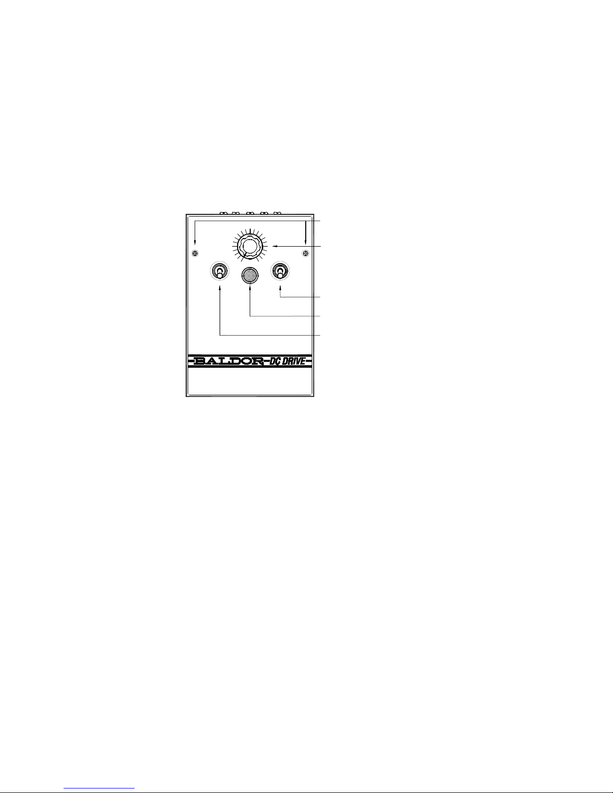
Figure 1-1 Cover Layout
(%) SPEED
FWD
1
0
REV
R
B
K
Motor
Before
to Stop
Reversing
Allow
0
3
0
20
50
4
0
ON
90
OFF
1
0
0
7
0
80
6
0
Two (2) Cover Screws
Recommended Tightening Torque: 5 lbs-in (6 kg-cm)
Main Speed Potentiometer
On/Off AC Line Switch
Pilot Light
Optional Forward-Brake-Reverse Switch
Note: See Section 6 for Voltage Select
Switch (Located Under Cover)
Page 17

17
Figure 1-2 Mechanical Specifications (Inches/[mm])
[178]
7.00
0.2
[5.08]
0.35
9.0
4X Ø
0.39
[9.91]
4X Ø
5.63
[143]
5.00
[105]
[127]
4.125
4.00
[102]
Back View is Shown Dimensioned
without Cover Installed
Side View is Shown Dimensioned with
Cover Installed and Optional
Forward-Brake-Reverse Switch
Two (2) Knockouts
for Standard
3/4” Fittings
Note: See Section 11 for optional Auxiliary Heat Sink (Catalog No. BC143) Mechanical Specifications.
Page 18

18
2. QUICK START
IMPORTANT – You must read these simplified operating instructions before you proceed.
These instructions are to be used as a reference only and are not intended
to replace the detailed instructions provided herein. You must read the
Safety Warnings and Cautions before proceeding.
Note: A Plug-In Horsepower Resistor
®
, an AC Line Fuse, and an Armature Fuse (supplied separately),
must be installed in order for this control to operate. See Section 4.
Figure 2-1
Plug-In
Fuse Horsepower Resistor®
Note: See Table 4-1 for Barrier Terminal Block wire size and recommended tightening torque
specifications. See Table 4-4 for Field connections (Shunt Wound Motors only).
Page 19

19
2.1 Connections
AC Line Connection: Connect the AC line input to Terminals L1 (Line Fuse) and L2, of the
Barrier Terminal Block, as shown in Figure 2-2 and as described in Section 4.
The Voltage Select Switch position must match the AC line input voltage. See Section 6.
Note: See Table 4-2 for AC Line and Armature Fuse selection. These items must be installed for the
control to operate.
Figure 2-2 AC Line, Armature, Field*, and Ground Connections
LINEFIELDARMATURE
A- A+ F- F+ L1 L2 GND
Barrier
Terminal Block
DC Motor
Ground (Earth)
Ground (Earth)
Armature
Field˙
115 or 208/230 Volts
AC Line Input
Note: *F- and F+ are Field connections for Shunt Wound Motors only.
2.2 Ground Connection
Connect all ground wires (earth), of connections to the control, to the green ground screw on
the chassis, as shown in Figure 2-2.
Page 20

20
2.3 AC Line Fusing
The control contains a built-in replaceable AC line fuse installed in the AC line fuse holder, as shown
in Figure 2-3. Select the correct replacement AC Line Fuse, as described in Table 4-2.
Note: If fuse blows, check for wrong connections and shorted or grounded motor.
2.4 Armature Fusing
Select an armature fuse (supplied separately) and install in the armature fuse holder, as shown in
Figure 2-3. Select the correct Armature Fuse as shown in Table 4-2. (See note below.)
2.5 Plug-In Horsepower Resistor
®
Select the correct Plug-In Horsepower Resistor® (supplied separately), according to armature
voltage and motor horsepower information in Table 4-2. Install the correct Plug-In Horsepower
Resistor
®
as shown in Figure 2-3. (See note below.)
Note: The Armature Fuse is supplied with the Plug-In Horsepower Resistor® Kit. See Table 4-3 for
Catalog No. and ratings.
2.6 Permanent Magnet (PM) Motor Armature Connection
Connect the motor armature to Terminals “A+” and “A-” of the Barrier Terminal Block, as shown in
Figure 2-2.
2.7 Motor Field (Shunt Wound Motors Only)
Connect the motor eld (of the shunt wound motor) to the Barrier Terminal Block. For full voltage
eld, use Terminals F+ (positive) and F- (negative). For half voltage eld, use Terminals F+ (positive)
and L1 (negative). See Section 4.
CAUTION! Do not connect motor armature leads to Terminals “F+” and “F-”. Do not use
Terminals “F+” and “F-” for any purpose other than to power the field of a shunt
wound motor. Shunt wound motors may be damaged if the field remains
energized without armature rotation for an extended period of time.
Page 21

21
2.8 Voltage Select Switch
The Voltage Select Switch must be set as described in Section 6. For 208/230 Volt AC line input,
set the Voltage Select Switch to the “230” position (factory setting). For 115 Volt AC line input, set
the Voltage Select Switch to the “115” position.
2.9 Trimpot Settings
All trimpots have been factory set for most applications, as shown in Figure 2-3. The trimpots may
be readjusted, as described in Section 7.
2.10 Diagnostic LEDs and Pilot Light
After power has been applied to the control, observe the front panel indicator and the board
mounted LEDs, to verify proper control operation, as described in Section 9.
2.11 Optional Auxiliary Heat Sink (BC143)
Extends the horsepower rating of the control to 1 HP, with 115 Volts AC line input, and 2 HP, with
230 volts AC line input. See Table 1-2 and Section 11.
2.12 Optional Forward-Brake-Reverse Switch (BC144)*
Used to dynamically brake the motor. It provides run/brake and forward-brake-reverse operations.
See Table 1-2 and Section 12.
* BC144 is factory installed on BC140-FBR model.
Page 22

22
Figure 2-3 Control Layout and Internal Connection Diagram
A- A+ F- F+ L1 L2 GND
F-
ARMATURE FIELD LINE
Page 23

23
3. INSTALLATION
3.1 Mounting
The control is designed with a NEMA-1 / IP-40 enclosure for indoor use. It is recommended that the
control be mounted vertically on a at surface with adequate ventilation. Leave enough room below the
control to allow for AC line and motor connections and any other connections that are required. A
mounting template is included to facilitate mounting of the control. See Figure 1-2.
Care should be taken to avoid extreme hazardous locations where physical damage can occur. The
control should be located in an area where it will not be exposed to contaminants such as water, metal
chips, solvents or excessive vibration.
Without the Auxiliary Heat Sink, the temperature around the control must not exceed 50°C (122°F). With
the Auxiliary Heat Sink, the temperature around the control must not exceed 40°C (104 °F).
The control is designed with a removable cover. To remove the cover, the two screws must be removed.
After mounting the control and all connections are completed, install the cover and secure it with the two
screws. Tighten the screws to 5 lbs-in (6 kg-cm). Do not overtighten.
Page 24

24
4. ELECTRICAL CONNECTIONS
See Table 4-1 for Barrier Terminal Block wire size and recommended tightening torque specications.
WARNING! READ SAFETY NOTICES BEFORE ATTEMPTING TO USE THIS CONTROL.
DISCONNECT THE MAIN POWER BEFORE MAKING CONNECTIONS TO THE
CONTROL.
WARNING! TO AVOID ERRATIC OPERATION, DO NOT BUNDLE AC LINE AND MOTOR
WIRES WITH WIRES FROM SIGNAL FOLLOWING, START/STOP CONTACTS,
OR ANY OTHER SIGNAL WIRES. ALSO DO NOT BUNDLE MOTOR WIRES
FROM MULTIPLE CONTROLS IN THE SAME CONDUIT. USE SHIELDED
CABLES ON ALL SIGNAL CONNECTIONS OVER 12”, (30CM). THE SHIELD
SHOULD BE EARTH GROUNDED ON CONTROL SIDE ONLY. WIRE THE
CONTROL IN ACCORDANCE WITH NATIONAL ELECTRICAL CODE
REQUIREMENTS AND OTHER LOCAL CODES THAT APPLY.
WARNING! DO NOT CONNECT SWITCHES OR RELAYS IN SERIES WITH ARMATURE OR
CATASTROPHIC FAILURE WILL RESULT.
CAUTION! The Voltage Select Switch position must match the AC line input voltage
(“115” position for 115 Volt AC line input and “230” position (factory setting)
for 208/230 Volt AC line input).
CAUTION! If control is connected to a transformer, it is advisable to switch the
secondary to disconnect power. If the primary is switched, additional
snubber capacitors may have to be added across the transformer output to
prevent damage to the power bridge.
Page 25

25
Table 4-1 Barrier Terminal Block Wire and Tightening Torque Specifications
Maximum
Motor
Current
(Amps DC)
90 – 130 Volt
DC Motors
(Maximum HP)
180 Volt
DC Motors
(Maximum HP)
Maximum Wire Size (Cu)
Recommended
Tightening
Torque
Maximum
50 Ft.
Maximum
100 Ft.
AWG mm
2
AWG mm
2
lb-in kg-cm
6 1/2 1 16 1.3 14 2.1 12 13.8
12 1 2 14 2.1 12 3.3 12 13.8
4.1 AC Line Connection
Connect the AC Line to terminals L1 (Line Fuse) and L2, as shown in Figure 2-2. If one of the AC line
inputs is a neutral (N), connect it to terminal L2.
Note: This control operates on 115 or 208/230 Volt AC line input and is factory set for 208/230 Volt AC
line input (Voltage Select Switch is factory set to the “230” position). See Section 6.
4.2 Ground Connection
Connect all ground wires (earth), of connections to the control, to the green ground screw on the
chassis, as shown in Figure 2-2.
4.3 AC Line and Armature Fusing
The AC Line fuse is factory installed. The Armature fuse (supplied separately) must be installed in the
armature fuse holder, as shown in Figure 2-3. Select the correct fuses, as shown in Table 4-2.
Fuses are available from your distributor. All fuses should be normal blow ceramic 3AG, MDA, or
equivalent. On domestic 230 Volt AC lines, separate branch circuit protection for each line must be
used.
Page 26

26
Table 4-2 Armature and AC Line Fuse Chart
Motor Horsepower
Approximate
Motor Current
(Amps DC)
Fuse Selection
(AC Amps)
90VDC 180VDC Armature Line
1/100 1/50 0.2 0.5 12
1/50 1/25 0.3 0.5 12
1/30 1/15 0.33 0.5 12
1/20 1/10 0.5 0.75 12
1/15 1/8 0.8 1 12
1/12 1/6 0.85 1.25 12
1/8 1/4 1.3 2 12
1/6 1/3 2 2.5 12
1/4 1/2 2.5 4 12
1/3 3/4 3.3 5 12
1/2 1 5.0 8 12
3/4 1½ 7.5 12 12
1* 2* 10 15 25
*With optional Auxiliary Heat Sink (Catalog No. BC143).
Page 27

27
4.4 AC Line Fuse
The AC Line Fuse acts as a disconnect in case of a catastrophic failure. If the AC Line Fuse blows, the
control is miswired, the motor is shorted or grounded, or the control is defective.
Note: Fuse each AC line conductor that is not at ground potential.
4.5 Armature Fuse
The Armature Fuse acts as a diagnostic indicator. If the Armature Fuse blows, it indicates that there
is a problem after the control’s output. The Armature Fuse required can be calculated by multiplying
the maximum DC Motor Current times 1.7.
4.6 Plug-In Horsepower Resistor
®
A Plug-In Horsepower Resistor® (supplied separately) must be installed to match the control to the
motor horsepower and voltage in order for the IR Compensation and Current Limit settings to be
correct. Select the proper Plug-In Horsepower Resistor
®
according to Table 4-3. Selecting the proper
Plug-In Horsepower Resistor
®
is as important as selecting the proper Armature Fuse.
Plug-In Horsepower Resistors
®
are available from your distributor. Install the Plug-In Horsepower
Resistor
®
, as shown in Figure 2-3.
Note: Be sure the Plug-In Horsepower Resistor
®
is inserted completely into the mating sockets.
Page 28

28
Table 4-3 Plug-In Horsepower Resistor® and Armature Fuse Kit Information
Motor Horsepower
Approximate
Motor Current
(Amps DC)
Plug-In Horsepower Resistor
®
and
Armature Fuse Kit
Armature
Voltage
90 – 130 Volts DC
Armature
Voltage
180 Volts DC
Plug-In
Horsepower
Resistor
®
Value
(Ohms)
Armature
Fuse
Rating
(Amps)
Catalog No.
1/100 1/50 0.2 1.0 0.5 BR1000
1/50 1/25 0.3 0.51 0.5 BR0510
1/30 1/15 0.33 0.35 0.5 BR0350
1/20 1/10 0.5 0.25 0.75 BR0250
1/15 1/8 0.8 0.25 1 BR0251
1/12 1/6 0.85 0.18 1.25 BR0180
1/8 1/4 1.3 0.1 2 BR0100
1/6 1/3 2 0.1 2.5 BR0101
1/4 1/2 2.5 0.05 4 BR0050
1/3 3/4 3.3 0.035 5 BR0035
1/2 1 5 0.025 8 BR0025
3/4 1½ 7.5 0.015 12 BR0015SP
1* 2* 10 0.01 15 BR0010SP
*With optional Auxiliary Heat Sink (Catalog No. BC143).
Page 29

29
4.7 Permanent Magnet (PM) Motor Armature Connection
Connect the motor armature positive lead (+) to Terminal “A+” and negative lead (-) to Terminal “A-”, on
the Barrier Terminal Board, as shown in Figure 2-3. Be sure the correct Plug-In Horsepower Resistor
®
and Armature Fuse are installed, as described in Section 4.
4.8 Shunt Wound Motor Field Connection (Shunt Wound Motors Only)
CAUTION! Do not connect motor armature leads to Terminals “F+” and “F-”. Do not use
Terminals “F+” and “F-” for any purpose other than to power the field of a shunt
wound motor. Shunt wound motors may be damaged if the field remains
energized without armature rotation for an extended period of time.
4.8.1 Full Voltage Field
Connect the eld positive (+) lead to Terminal “F+” and the negative lead (-) to Terminal “F-”, on the
Barrier Terminal Block, and as described in Table 4-4. See Figure 2-3.
4.8.2 Half Voltage Field
For 50 Volt DC with 100 Volt rated armature, use Terminal “L1” and F+, on the terminal board, as
described in Table 4-4. See Figure 2-3.
Table 4-4 Field Connection (Shunt Wound Motors Only)
AC Input Voltage
(Volts AC)
Voltage Selector
Switch (Position)
Armature Voltage
(Volts DC)
Field Voltage
(Volts DC)
Terminal
Connections
115 115
0 – 90
100 F+, F-
50 F+, L1
208/230 230
0 – 180 200 F+, F-
0 – 90* 100 F+, L1
*Step-down operation.
Page 30

30
5. IMPORTANT APPLICATION INFORMATION
WARNING! DO NOT USE THIS CONTROL IN AN EXPLOSIVE ENVIRONMENT. AN
EXPLOSION CAN CAUSE SERIOUS OR FATAL INJURY. THIS CONTROL IS
NOT EXPLOSION PROOF.
WARNING! BE SURE TO FOLLOW ALL INSTRUCTIONS CAREFULLY. FIRE OR
ELECTROCUTION CAN RESULT DUE TO IMPROPER USE OF THIS
PRODUCT. READ SAFETY NOTICES.
5.1 Motor Type
The BC140 / BC140-FBR is designed for permanent magnet (PM) and Shunt Wound DC motors.
Controls operated on 115 Volt AC line input are designed for 90 Volt SCR rated motors. Controls
operated on 230 Volt AC line input are designed for 180 and 90 Volt (step-down) SCR rated motors. Use
of higher voltage motors will result in a reduction of the available maximum speed. Also, if motor is not
an SCR rated type, the actual AC line amperage of the control, at full load, should not exceed the
motor’s DC nameplate rating.
5.2 Torque Requirements
The motor selected for the application must be capable of supplying the necessary torque. In order to
ensure the motor is not overloaded, a DC ammeter should be connected in series with the armature. Be
sure the current under full load does not exceed the motor nameplate rating.
5.3 Acceleration Start
The BC140 / BC140-FBR contains an adjustable acceleration start feature which allows the motor to
smoothly accelerate from zero speed to full speed over a time period of 0.2 – 10 seconds. The
acceleration trimpot (ACCEL) is factory set for 2 seconds.
Page 31

31
5.4 Limitation In Use
The BC140 / BC140-FBR control is designed for use on machine applications.
WARNING! DO NOT SWITCH THE ARMATURE IN AND OUT OF CIRCUIT OR
CATASTROPHIC FAILURE WILL RESULT. IF ARMATURE SWITCHING IS
REQUIRED, USE BC144 FORWARD-BRAKE-REVERSE SWITCH KIT.
CAUTION! Contact your local Baldor District Office before using this control on constant
horsepower applications such as saws and drill presses. Do not use this
control in an explosive atmosphere. Be sure the BC140 / BC140-FBR is used
within its ratings. Follow all instructions carefully.
Page 32

32
6. SETTING THE VOLTAGE SELECT SWITCH
WARNING! READ ALL SAFETY NOTICES BEFORE ATTEMPTING TO OPERATE THE CONTROL
OR SEVERE INJURY OR DEATH CAN RESULT. FAILURE TO FOLLOW THE
WARNINGS AND CAUTIONS, MAY RESULT IN ELECTRIC SHOCK, FIRE OR
EXPLOSION.
The Voltage Select Switch is located under the cover and must be set before applying power to the control.
See Figure 6-1.
6.1 For 208/230 Volt AC Line Input
Set the Voltage Select Switch to the “230” position (factory setting). The switch toggle should be in the
lower position with “230” displayed at the top.
6.2 For 115 Volt AC Line Input
Set the Voltage Select Switch to the “115” position. The switch toggle should be in the upper position
with “115” displayed at the bottom.
Figure 6-1 Voltage Select Switch Setting
208/230 Volt AC Line Input
(Factory Setting) 115 Volt AC Line Input
Page 33

33
7. TRIMPOT ADJUSTMENTS
The control contains trimpots which have been factory set for most applications. Figure 2-3 illustrates the
location of the trimpots and their approximate factory set positions. Some applications may require
readjustment of the trimpots in order to set the control for a specic requirement. See Table 1-5 for range and
factory setting of all trimpots. The trimpots may be readjusted as follows.
WARNING! IF POSSIBLE, DO NOT ADJUST TRIMPOTS WITH THE MAIN POWER APPLIED.
IF ADJUSTMENTS ARE MADE WITH THE MAIN POWER APPLIED, AN
INSULATED ADJUSTMENT TOOL MUST BE USED AND SAFETY GLASSES MUST
BE WORN. HIGH VOLTAGE EXISTS IN THIS CONTROL. ELECTROCUTION CAN
RESULT IF CAUTION IS NOT EXERCISED. SAFETY NOTICES AND MUST BE
READ AND UNDERSTOOD BEFORE PROCEEDING.
7.1 Acceleration Trimpot (ACCEL)
The ACCEL Trimpot is provided to allow for a smooth start over an adjustable time period each time the
AC power is applied or the Main Speed Potentiometer is adjusted to a higher speed. The ACCEL
Trimpot is factory set to 2 seconds, which is the amount of time it will take for the motor to accelerate
from zero speed to full speed. To increase the acceleration time, rotate the ACCEL Trimpot clockwise. To
decrease the acceleration time, rotate the ACCEL Trimpot counterclockwise. The ACCEL Trimpot range
is 0.2 – 10 seconds.
See Figure 7-1.
Figure 7-1 Accel Trimpot Range
Page 34

34
7.2 Deceleration Trimpot (DECEL)
The DECEL Trimpot controls the amount of rampdown time when the Main Speed Potentiometer is
adjusted to a lower speed. The DECEL Trimpot is factory set to 2 seconds, which is the amount of time
it will take for the motor to decelerate from full speed to zero speed. To increase the deceleration
time, rotate the DECEL Trimpot clockwise. To decrease the deceleration time, rotate the DECEL Trimpot
counterclockwise. The DECEL Trimpot range is 0.2 – 10 seconds.
See Figure 7-2.
Note: If the DECEL Trimpot is set to greater than the natural coast time of the motor and actual load, it
will extend the deceleration time of the motor.
Figure 7-2 Decel Trimpot Range
7.3 Minimum Speed Trimpot (MIN)
The MIN Trimpot sets the minimum speed of the motor when the Main Speed Potentiometer is set fully
counterclockwise. The MIN Trimpot is factory set to 0% of base motor speed. To increase the minimum
speed, rotate the MIN Trimpot clockwise. To decrease the minimum speed, rotate the MIN Trimpot
counterclockwise. The MIN Trimpot range is 0% – 30% of base motor speed.
See Figure 7-3.
Note: Readjusting the MIN Trimpot will affect the maximum speed setting. Therefore, it is necessary to
readjust the MAX Trimpot if readjusting the MIN Trimpot. It may be necessary to repeat these
adjustments until both the minimum and maximum speeds are set to the desired levels.
Figure 7-3 Min Trimpot Range
Page 35

35
7.4 Maximum Speed Trimpot (MAX)
The MAX Trimpot sets the maximum speed of the motor when the Main Speed Potentiometer is set fully
clockwise. The MAX Trimpot is factory set to 100% of base motor speed. To increase the maximum
speed, rotate the MAX Trimpot clockwise. To decrease the maximum speed, rotate the MAX Trimpot
counterclockwise. The MAX Trimpot range is 50% – 110% of base motor speed.
See Figure 7-4.
Note: Do not adjust the maximum speed above the rated motor RPM or unstable operation may occur. For
moderate changes in the maximum speed, there will be a slight effect on the minimum speed setting
when the minimum is set to zero. There may be significant variation in the minimum speed setting if
the minimum speed is at a higher than zero setting.
Figure 7-4 Max Trimpot Range
Page 36

36
7.5 Current Limit Trimpot (CL)
The CL Trimpot is used to limit the maximum current (torque) to the motor. The CL also protects the control
from excessive current during startup. The CL Trimpot is factory set to 150% of the full load current rating
of the motor. To increase the current limit, rotate the CL Trimpot clockwise (do not exceed 200% of the full
load current rating of the motor (maximum clockwise position)). To decrease the current limit, rotate the
CL Trimpot counterclockwise. On cyclical loads, it may be normal for the CL LED to momentarily ash.
(Visible only if the cover is removed.) The CL Trimpot range is 0% – 200% of the full load current rating of
the motor. Some application may require a lower value so as not to damage process material or drive train
components.
See Figure 7-5.
Note: In order for the Current Limit to operate properly, the correct Plug-In Horsepower Resistor® must
be installed for the particular motor and input voltage being used, as described in Section 4.
Calibration of the CL Trimpot is normally not required when the proper Plug-In Horsepower
Resistor
®
is installed.
Figure 7-5 CL Trimpot Range
Page 37

37
To Recalibrate the CL Trimpot:
1. Disconnect the AC power and connect a DC ammeter in series with either motor armature lead.
If only an AC ammeter is available, connect it in series with either AC line input lead.
2. Set the Main Speed Potentiometer to approximately 30% – 50% clockwise position.
3. Set the CL Trimpot fully counterclockwise. The CL LED will illuminate red.
4. Load the motor shaft in accordance with application requirements.
Apply power and rotate the CL Trimpot clockwise until the desired current reading is observed on the DC
ammeter. Factory Current Limit setting is 150% of the full load current rating of the motor. If using an AC
ammeter connected in the AC line input, the factory Current Limit setting will read 75% of the full load
current rating of the motor. Do not exceed 200% of the full load current rating of the motor (maximum
clockwise position).
WARNING! DO NOT LEAVE MOTOR SHAFT LOCKED FOR MORE THAN 2 – 3 SECONDS
OR MOTOR DAMAGE MAY RESULT.
Page 38

38
7.6 IR Compensation Trimpot (IR)
The IR Trimpot sets the amount of compensating voltage required to keep the motor speed constant
under varying loads. If the load does not vary substantially, the IR Trimpot may be set to a minimum
level (approximately 1/4 of full clockwise rotation). The IR Trimpot is factory set to provide 3 Volts of
compensation for controls with 90 Volt DC output and 6 Volts of compensation for controls with 180
Volt DC Output. To increase the amount of compensating voltage, rotate the IR Trimpot clockwise. To
decrease the amount of compensating voltage, rotate the IR Trimpot counterclockwise.
See Figure 7-6.
Note: In order for the IR Compensation to operate properly, the correct Plug-In Horsepower Resistor
®
must be installed for the particular motor and input voltage being used, as described in Section
4. Calibration of the IR Trimpot is normally not required when the proper Plug-In Horsepower
Resistor
®
is installed. Excessive IR Compensation will cause the motor to become unstable,
which causes cogging (“hunting” or “zooming”).
Figure 7-6 IR Trimpot Range
Page 39

39
To Recalibrate the IR Trimpot:
1. Set the IR Trimpot to approximately 25% rotation.
2. Run the motor unloaded at approximately 1/3 speed and record the RPMs.
3. Run the motor with the maximum load and adjust the IR Trimpot so that the motor speed under
load equals the unloaded speed recorded in step 2.
4. Remove the load and recheck the RPMs.
If the unloaded RPM has changed, repeat steps 2 and 4 for better regulation. The control is now
compensated to provide minimal speed change due to changing loads.
Page 40

40
8. OPERATION
WARNING! READ SAFETY NOTICES BEFORE OPERATING THIS CONTROL OR SEVERE
INJURY OR DEATH CAN RESULT.
8.1 With no AC power applied and the On/Off AC Line Switch set to the “OFF” position, remove the front
cover by unscrewing the two cover screws. See Figure 1-1.
8.2 Set the Voltage Select Switch to the correct position, corresponding to the AC line input voltage.
(“115” position for 115 Volt AC line input and “230” position (factory setting) for 208/230 Volt AC line
input). See Figure 1-1.
8.3 Install the correct Armature Fuse, as shown in Table 4-2 and the correct Plug-In Horsepower
Resistor
®
as shown in Table 4-3.
8.4 Recheck all input AC line and motor connections. See Figure 2-2.
8.5 Set the Main Speed Potentiometer to 0% (fully counterclockwise).
8.6 Set the Forward-Brake-Reverse Switch (if installed) to the “FWD” or “REV” position.
8.7 Set the On/Off AC Line Switch to the “ON” position. Observe that the Pilot Light illuminates.
Gradually increase the Main Speed Potentiometer. The motor should smoothly come up to the
desired speed and remain stable.
Page 41

41
9. DIAGNOSTIC LEDS AND PILOT LIGHT
The BC140 / BC140-FBR has PC board mounted LEDs, to display the control’s operational status and a
panel-mounted Pilot Light. See Figure 2-3 for the location of the LEDs.
9.1 Power On (PWR ON) LED and Pilot Light
When the AC power is applied to the control and the On/Off AC Line Switch is set “ON”, the PWR
ON LED, on the PC board, will illuminate green and the Pilot Light, on the front cover, will
illuminate orange.
9.2 Current Limit (CL) LED
The CL LED will illuminate red when the motor is overloaded, indicating that the current limit set
point has been reached (set by the CL Trimpot). See Section 7.
Page 42

42
10. TROUBLESHOOTING
Table 10-1 is a troubleshooting guide for controls without the optional Forward-Brake Reverse Switch
installed. Table 10-2 is a troubleshooting guide for controls with the Forward-Brake-Reverse Switch
installed. Both tables provide information on symptoms, their possible causes, and suggested corrective
actions.
WARNING! HIGH VOLTAGE IS PRESENT IN THIS CONTROL. DISCONNECT MAIN POWER
BEFORE MAKING CONNECTIONS TO THE CONTROL. THE COVER MUST BE
PROPERLY SECURED, AFTER ALL SETUP CONNECTIONS, AND
ADJUSTMENTS ARE COMPLETE. THIS REDUCES ELECTRICAL SHOCK
HAZARD. FAILURE TO OBSERVE THIS WARNING COULD RESULT IN
ELECTRICAL SHOCK OR ELECTROCUTION.
WARNING! HIGH VOLTAGE IS PRESENT IN THE CONTROL. IF POSSIBLE, DO NOT
ADJUST TRIMPOTS WITH THE MAIN POWER APPLIED. IF ADJUSTMENTS
ARE MADE WITH THE MAIN POWER APPLIED, AN INSULATED ADJUSTMENT
TOOL (PROVIDED) MUST BE USED AND SAFETY GLASSES MUST BE WORN.
FIRE AND/OR ELECTROCUTION CAN RESULT IF CAUTION IS NOT
EXERCISED.
Page 43

43
Table 10-1 provides information on symptoms, possible causes, and the suggested corrective action for
controls without optional forward-brake-reverse switch installed.
Table 10-1 Troubleshooting Guide for Controls without Optional Forward-Brake-Reverse Switch Installed
Symptom Possible Cause Suggested Corrective Action
Motor is not running and
Pilot Light not illuminated.
On/Off AC Line Switch in “Off”
Position.
Set On/Off Switch to “On” Position.
Blown Line fuse. Replace Line Fuse. See Table 4-2.
Defective On/Off AC Line Switch, Replace On/Off AC Line Switch.
Motor does not run and
Pilot Light is illuminated.
Main Speed Potentiometer set fully
counterclockwise.
Rotate Main Speed potentiometer
clockwise.
Defective motor.
Check for defective motor, worn
brushes, etc. Replace motor, if
necessary.
Plug-In Horsepower Resistor
®
not
installed.
Install the correct Plug-In
Horsepower Resistor
®
. See Table
4-3.
Blown Armature Fuse.
Replace Armature Fuse. See Table
4-2.
CL Trimpot set fully
counterclockwise.
Set CL Trimpot, as described in
Section 7.
Motor hums, runs at very
low speed, or slows down
substantially when load is
applied.
Low AC line input voltage. Check AC line input voltage.
Page 44

44
Symptom Possible Cause Suggested Corrective Action
Erratic motor performance.
Overload condition. Remove overload.
Incorrect Plug-In Horsepower
Resistor
®
.
Install the correct Plug-In
Horsepower Resistor
®
. See Table
4-3.
CL and/or IR Trimpots may be set
incorrectly.
Readjust the CL and/or IR Trimpots,
as described in Section 7.
Defective speed control module. Replace speed control.
Voltage Select Switch set to wrong
position.
Recheck line voltage and the
correct setting of the Voltage Select
Switch, as described in Section 6.
Defective motor, worn brushes, etc. Repair or replace motor.
Motor continues to run with
Main Speed Potentiometer
set fully counterclockwise.
MIN speed trimpot set higher than
0% of base speed.
Readjust the MIN Trimpot, as
described in Section 7.
IR Comp trimpot set too high.
Readjust the IR Trimpot, as
described in Section 7.
Motor runs in wrong
direction.
Motor armature leads are reversed. Reconnect motor armature leads.
Table 10-1 Troubleshooting Guide for Controls without Optional Forward-Brake-Reverse
Switch Installed (Continued)
Page 45

45
Table 10-2 provides information on symptoms, possible causes, and the suggested corrective action for
controls with optional forward-brake-reverse switch installed.
Table 10-2 Troubleshooting Guide for Controls with Optional Forward-Brake-Reverse Switch Installed
Symptom Possible Cause Suggested Corrective Action
Motor will not run in
Forward or Reverse
direction.
Faulty wiring or loose connections
to the reversing switch.
Correct the connections. See
Figure 12-1.
Forward-Brake-Reverse defective.
Switch is defective.
Replace Forward-Brake-Reverse
Switch assembly.
No braking action in brake
mode.
Faulty connections or loose
connections.
Check and correct connections.
Defective Brake Resistor.
Replace Forward-Brake-Reverse
Switch assembly.
Page 46

46
11. OPTIONAL AUXILIARY HEAT SINK (CATALOG NO. BC143)
The optional Auxiliary Heat Sink (Catalog No. BC143) is used to increase the rating of the control. See Table
1-3.
The control is mounted on the four (4) holes with four (4) mounting screws (supplied), as shown in Figure
11-1.
Figure 11-1 Optional Auxiliary Heat Sink Mechanical Specifications
[34.9]
1.375
6.29
[160]
7.00
[178]
[142]
5.61
[143]
5.63
Page 47

47
12. OPTIONAL FORWARD-BRAKE-REVERSE SWITCH (CATALOG NO. BC144)*
WARNING! READ SAFETY NOTICES BEFORE USING THIS CONTROL. DISCONNECT THE
MAIN POWER BEFORE MAKING CONNECTIONS TO THE CONTROL.
The optional Forward-Brake-Reverse Switch (Catalog No. BC144)* is used to dynamically brake the motor
and reverse motor direction. The switch assembly is to be installed in the mounting hole provided on the
control.
See the installation instructions MN1372, provided with the Forward-Brake-Reverse Switch kit for detailed
information on mounting and connections.
Figure 12-1 shows the connections of the Forward-Brake-Reverse Switch to the speed control and the
Barrier Terminal Block.
* BC144 is factory installed on BC140-FBR model.
Figure 12-1 Optional Forward-Brake-Reverse Switch Connections
Page 48

48
NOTES:
_____________________________________________________________________________________________
_____________________________________________________________________________________________
_____________________________________________________________________________________________
_____________________________________________________________________________________________
_____________________________________________________________________________________________
_____________________________________________________________________________________________
_____________________________________________________________________________________________
_____________________________________________________________________________________________
_____________________________________________________________________________________________
_____________________________________________________________________________________________
_____________________________________________________________________________________________
_____________________________________________________________________________________________
_____________________________________________________________________________________________
_____________________________________________________________________________________________
Page 49

49
LIMITED WARRANTY
For a period of 2 years from date of original purchase, BALDOR will repair or replace without
charge controls which our examination proves to be defective in material or workmanship. This
warranty is valid if the unit has not been tampered with by unauthorized persons, misused,
abused, or improperly installed and has been used in accordance with the instructions and/
or ratings supplied. This warranty is in lieu of any other warranty or guarantee expressed or
implied. BALDOR shall not be held responsible for any expense (including installation and
removal), inconvenience, or consequential damage, including injury to person, caused by items
of our manufacture or sale. (Some states do not allow the exclusion or limitation of incidental or
consequential damages, so the above exclusion may not apply.) In any event, BALDOR’s total
liability, under all circumstances, shall not exceed the full purchase price of the control. Claims for
purchase price refunds, repairs or replacements must be referred to BALDOR with all pertinent
data as to the defect, the date purchased, the task performed by the control, and the problem
encountered. No liability is assumed for expendable items such as fuses.
Goods may be returned only with written notication including a BALDOR Return Authorization
Number and any return shipments must be prepaid.
Page 50

50
Baldor District Offices - United States Locations
MASSACHUSETTS
BOSTON
6 PULLMAN STREET
WORCESTER, MA 01606
PHONE: 508-854-0708
FAX: 508-854-0291
MICHIGAN
DETROIT
5993 PROgRESS DRivE
STERLiNg HEigHTS, Mi 48312
PHONE: 586-978-9800
FAX: 586-978-9969
MINNESOTA
MINNEAPOLIS
21080 134TH AvENUE NORTH
ROgERS, MN 55374
PHONE: 763-428-3633
FAX: 763-428-4551
MISSOURI
ST LOUI S
13678 LAkEFRONT DRivE
EARTH CiTy, MO 63045
PHONE: 314-373-3032
FAX: 314-373-3038
KA NSAS CITY
1501 BEDFORD AvENUE
NORTH kANSA S CiTy, MO 64116
PHONE: 816-587-0272
FAX: 816-587-3735
NEW YORK
AUBURN
ONE ELLiS DRivE
AUBURN, Ny 13021
PHONE: 315-255-3403
FAX: 315-253-9923
FLORIDA
TAMPA/PUERTO RICO/
VIRGIN ISLANDS
3906 EAST 11TH AvENUE
TAMPA, FL 33605
PHONE: 813-248-5078
FA X: 813-247-2984
GEORGIA
ATLANTA
62 TECHNOLOgy DRivE
ALPHARETTA, gA 30005
PHONE: 770-772-7000
FA X: 770-772-7200
ILLINOIS
CHICAGO
340 REMiNgTON BLvD.
BOLiNgBROOk, iL 60440
PHONE: 630-296-1400
FAX: 630-226-9420
INDIANA
INDIANAPOLIS
5525 W. MiNNESOTA STREE T
iNDiANAPOLiS, iN 46241
PHONE: 317-246-5100
FAX: 317-246-5110
IOWA
DES MOINES
1800 DiXON STREET, SUiTE C
DES MOiNES, iA 50316
PHONE: 515-263-6929
FA X: 515-263- 6515
MARYLAND
BALTIMORE
6660 SANTA BARBAR A RD.
SUiTES 22-24
ELkRiDgE, MD 21075
PHONE: 410-579-2135
FAX: 410-579-2677
UNITED STATES
ARIZONA
PHOENIX
4211 S 43RD PL ACE
PHOENiX, AZ 85040
PHONE: 602-470-0407
FAX: 602-470-0464
ARKANSAS
CLARKSVILLE
1001 COLLEgE AvENUE
CLARkSviLLE, AR 72830
PHONE: 479-754-9108
FAX: 479-754-9205
CALIFORNIA
LOS ANGELES
6480 FLOTiLLA STREET
COMMERCE, CA 90040
PHONE: 323-724-6771
FAX: 323-721-5859
HAYWARD
21056 FORBES AvENUE
HAyWARD, CA 94545
PHONE: 510-785-9900
FA X: 510-785-9910
COLORADO
DENVER
3855 FOREST STREET
DENvER, CO 80207
PHONE: 303-623-0127
FAX: 303-595-3772
CONNECTICUT
WALLINGFORD
65 SOUTH TURNPikE ROAD
WALLiNgFORD, CT 06492
PHONE: 203-269-1354
FAX: 203-269-5485
NORTH CAROLINA
GREENSBORO
1220 ROTHERWOOD ROAD
gREENSBORO, NC 27406
PHONE: 336-272-6104
FAX: 336-273-6628
OHIO
CINCINNATI
2929 CRESCENTviLLE ROAD
WEST CHESTER, OH 45069
PHONE: 513-771-2600
FA X: 513-772-2219
CLEVELAND
8929 FREEWAy DRivE
MACEDONiA, OH 44056
PHONE: 330-468-4777
FAX: 330-468-4778
OKLAHOMA
TULSA
7170 S. BRADEN, SUiTE 140
TULSA, Ok 74136
PHONE: 918-366-9320
FAX: 918-366-9338
OREGON
PORTL AND
12651 SE CAPPS ROAD
CL ACkAMAS, OR 97015
PHONE: 503-691-9010
FAX: 503-691-9012
PENNSYLVA NIA
PHILADELPHIA
1035 THOMAS BUSCH
MEMORiAL HigHWAy
PENNSAUkEN, NJ 08110
PHONE: 856-661-1442
FAX: 856-663-6363
PITTSBURGH
159 PROMiNENCE DRivE
NE W kENSiNgTON, PA 15068
PHONE: 724-889-0092
FAX: 724-889-0094
TENNESSEE
MEMPHIS
4000 WiNCHESTER ROAD
MEMPHiS, TN 38118
PHONE: 901-365-2020
FAX: 901-365-3914
TEXAS
DALLAS
2920 114TH STREE T SUiTE 100
gR AND PRAiRiE, TX 75050
PHONE: 214-634-7271
FAX: 214-634-8874
HOUSTON
10355 W. LiTTLE yORk ROAD
SUiTE 300
HOUSTON, T X 77041
PHONE: 281-977-6500
FAX: 281-977-6510
UTAH
SALT L AKE CITY
2230 SOUTH MAiN STREET
SALT LA kE CiTy, UT 84115
PHONE: 801-832-0127
FAX: 801-832-8911
WISCONSIN
MILWAUKEE
1960 SOUTH CALHOUN ROAD
NE W BERLiN, Wi 53151
PHONE: 262-784-5940
FAX: 262-78 4-1215
Page 51

51
Baldor District Offices - International Locations
INTERNATIONAL SALES
FORT SMITH, AR
P.O. BOX 2400
FORT SMiTH, AR 72902
PHONE: 479-646-4711
FAX: 479-648-5895
CANADA
EDMONTON, ALBERTA
4053-92 STREE T
EDMONTON, ALBERTA T6E 6R8
PHONE: 780-434-4900
FAX: 780-438-2600
TORONTO
OAKVILLE, ONTARIO
2750 COvENTRy ROAD
OAkviLLE, ONTARiO L6H 6R1
PHONE: 905-829-3301
FAX: 905-829-3302
MONTREAL, QUEBEC
5155 J-ARMAND BOMBARDiER
SAiNT-HUBERT, QUéBEC
CANADA J3Z 1g4
PHONE: 514-933-2711
FAX: 514-933-8639
VANCOUVER,
BRITISH COLUMBIA
1538 kEBET WAy
PORT COQUiTLAM,
BRiTiSH COLUMBi A v3C 5M5
PHONE 604-421-2822
FAX: 604-421-3113
WINNIPEG, MANITOBA
54 PRiNCESS STREET
WiNNiPEg, MANiTOBA R3B 1k2
PHONE: 204-942-5205
FAX: 204-956-4251
AUSTRALIA
UNiT 3, 6 STANTON ROAD
SE vEN HiLLS, NSW 2147,
AUSTRALiA
PHONE: (61) (2) 9674 5455
FA X: (61) (2) 9674 2495
UNiT 8, 5 k ELLETTS ROAD
ROWviLLE, viCTORiA, 3178
AUSTRALiA
PHONE: (61) (3) 9753 4355
FA X: (61) (3) 9753 4366
EL SALVADOR
RESiDENCiAL PiNARES DE SUiZA
POL. 15 #44,
NvA. SAN SALvADOR, EL
SALvADOR
PHONE: +503 2288-1519
FA X: +503 2288-1518
CHILE
LUiS THAyER OJEDA 166,
OF 402 - PROviDENCiA
SANTiAgO, CHiLE
PHONE: +56 2 964-3210
CHINA
160 SONg SHENg ROAD
SONgJiANg iNDUSTRy ZONE
SHANgHAi 201613, CHiNA
PHONE: +86 21 5760 5335
FA X : +86 21 5760 5336
GERMANY
HERMANN-HEiNRiCH-gOSSEN STR AS SE 3
kÖLN, D-50858 gERMANy
PHONE: +49 2234 37941-0
FA X: +49 2234 3794164
DiESELSTRASSE 22
kiRCHHEiM, D-85551
MUNiCH, gERMANy
PHONE: +49 89 90508-0
FA X: +49 89 9050886
INDIA
OFFiCE NO 517 & 518,
5TH FLOOR, SiDDHARTH TOWERS,
CTS NO. 421 (1), SURvEy NO 12,
kOTHRUD, PUNE 411 038,
MAHARASHTRA, iNDiA
PHONE: + 91 20 25 45 27 17
FAX: + 91 20 25 45 27 19
INDONESIA
TAL AvERA OFFiCE PARk,
28TH FLOOR, SUiTE M18
Ji. T.B. SiM ATUPANg, kAv. 22-26
CiLANDAk, JAkARTA SELATAN, 12430
iNDONESiA
PHONE: +62 21 75 999 879
FA X: + 62 21 75 999 878
ITA LY
viA SOT TOBiSiO 30
CH-6828 BALERNA
SWiTZERLAND
PHONE: +41 91 683 6161
FA X: +41 91 630 2633
JAPAN
DiA BLDg 802,
2-21-1 TSURUyA-CHO,
kANAgAWA-kU
yOkOHAMA, 221-0835, JAPAN
PHONE: 81-45-412-4506
FAX: 81-45-412-4507
KOREA
RM#1715, SUSEO TOWER, 725,
SUSEO-DONg, gANgNAM-gU,
SEOUL 135-757 kOREA
PHONE: (82) 2 2226 9369
FA X: (82) 2 2226 9368
MEXICO
LEON, GUANAJUATO
kM. 2.0 BLvD. AEROPUERTO
LEÓN 37545, gUAN AJUATO, MéXiCO
PHONE: +52 477 761 2030
FA X: +52 477 761 2010
MIDDL E EAST & NORTH AFRICA
vSE iNTERNATiONAL CORP.
3233 N ARLiNgTON HEigHTS ROAD
SUiTE 100W
ARLiNgTON HEigHTS, iL 60004 USA
PHONE: 847 590 5547
FA X: 847 590 5587
PANAMA
AvE. RiCARDO J. ALFARO
EDiFiCiO SUN TOWERS MALL
PiSO 2, LOCAL 55
CiUDAD DE PANAMá, PANAMá
PHONE: +507 236-5155
FAX: +507 236-0591
SINGAPORE
18 kAki BUkiT ROAD 3, #03-09
ENTREPRENEUR BUSiNESS CENTRE
SiNgAPORE 415978
PHONE: (65) 6744 2572
FA X: (65) 6747 1708
SWITZERLAND
POST FACH 73
SCHUETZENSTRASSE 59
FEUERTHALEN, CH-8245
SWiTZERLAND
PHONE: +41 52 647 4700
FA X: +41 52 659 2394
TAIWAN
1F, NO 126 WENSHAN 3RD STREET,
NANTUN DiSTRiCT,
TAiCHUNg CiTy 408
TAiWAN R.O.C
PHONE: (886) 4 238 04235
FA X: (886) 4 238 04463
UNITED KINGDOM
6 BRiSTOL DiSTRiBUTiON PARk
HAWkLEy DRivE
BRiSTOL BS 32 0BF U.k.
PHONE: +44 1454 850000
FA X: +44 1454 859001
VENEZUELA
Av. ROM A. QTA EL MiL AgRO. URB.
CALiFORNiA NORTE
CARACAS, 1070
vENEZUELA
PHONE /FAX: +58 212 272 7343
MOBiLE: +58 414 114 8623
Page 52

*703-1111*
© Baldor Electric Company
MN703
All Rights Reserved. Printed in USA.
(A40244B) - Rev D - 11/11
P.O. Box 2400, Fort Smith, AR 72902-2400 U.S.A., Ph: (1) 479.646.4711, Fax (1) 479.648.5792, International Fax (1) 479.648.5895
Baldor - Dodge
6040 Ponders Court, Greenville, SC 29615-4617 U.S.A., Ph: (1) 864.297.4800, Fax: (1) 864.281.2433
www.baldor.com
 Loading...