

Page 1
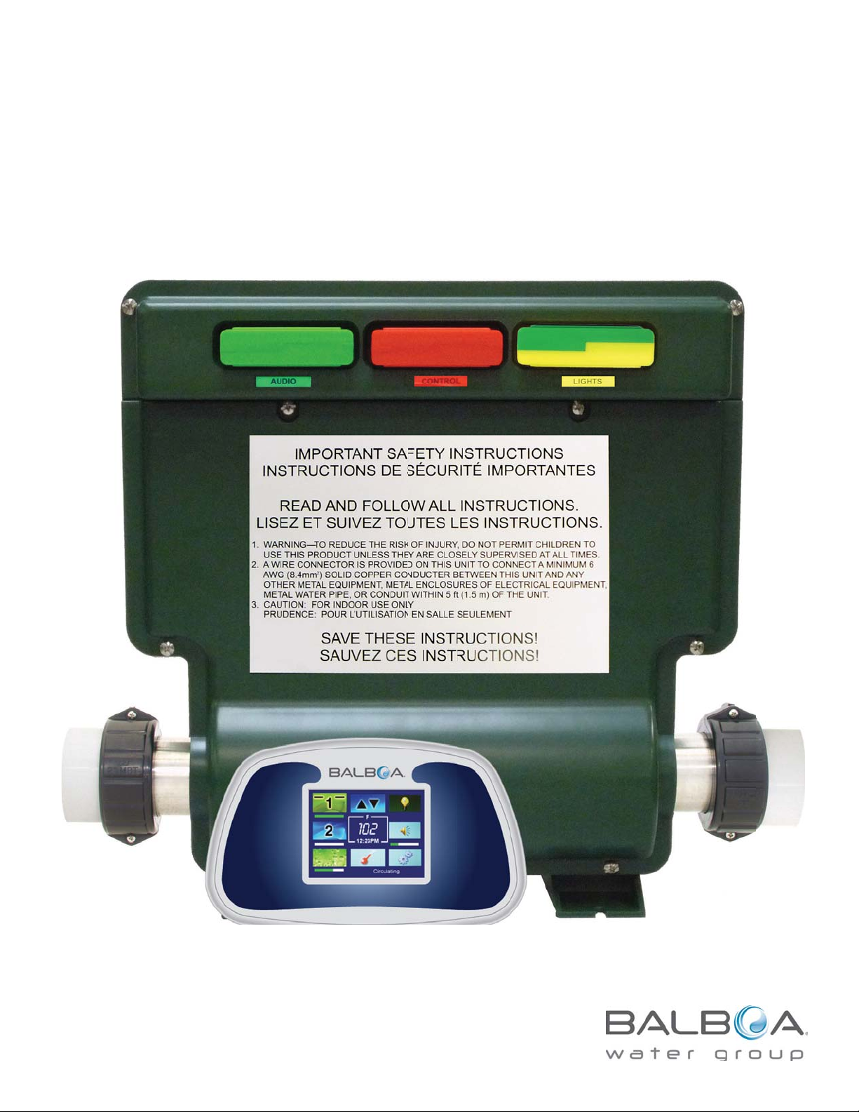
LM8 - Low Maintenance System User Manual
1
Page 2

Important Notices
INTELLECTUAL PROPERTY ADVISEMENT
All Intellectual property, as defined below, owned by or
which is otherwise the property of Balboa Water Group or
its respective suppliers relating to the Balboa Water Group
LM8 Low Maintenance System, including but not limited
to, accessories, parts, or software relating there to (the
“LM8 - Low Maintenance System”), is proprietary to Balboa
Water Group and protected under federal laws, state laws,
and international treaty provisions. Intellectual Property
includes, but is not limited to, inventions (patentable or
unpatentable), patents, trade secrets, copyrights, software,
computer programs, and related documentation, and other
works of authorship. You may not infringe or otherwise violate
the rights secured by the Intellectual Property. Moreover,
you agree that you will not (and will not attempt to) modify,
prepare derivative works of, reverse engineer, decompile,
disassemble, or otherwise attempt to create source code
from the software. No title to or ownership in the Intellectual
Property is transferred to you. All applicable rights of the
Intellectual Property shall remain with Balboa Water Group
and its suppliers.
END USER WARNING
This Installation Manual is provided solely to aid qualified spa
service technicians in installing spas with control systems
manufactured by Balboa Water Group. Balboa controls have
absolutely no end user serviceable parts. Balboa Water Group
does not authorize attempts by the spa owner/user to repair or
service any Balboa products. Non-qualified users should never
open or remove covers, as this will expose dangerous voltage
points and other dangerous risks. Please contact your dealer or
authorized repair center for service.
WARNINGS: DANGER! RISK OF ELECTRIC SHOCK!
All electrical work must be performed by a qualified UÊ
electrician and must conform to all national, state, and
local codes.
Before making any electrical connections, make certain UÊ
that the Main Power breaker from the house breaker box
has been turned off.
Do not attempt service of this control system. Contact UÊ
your dealer or service organization for assistance.
Do not permit any electric appliance, such as a light, UÊ
telephone, radio, or television within 5’ (1.5m) of a pool
or spa.
Follow all owner’s manual UÊ power connection
instructions.
Installation must be performed by a licensed electrician UÊ
and all grounding connections must be properly
installed.
No user serviceable parts.UÊ
Water temperature in excess of 38˚C may be injurious to UÊ
your health.
Disconnect the electrical power before servicing.UÊ
Keep access door closed.UÊ
CAUTION
UÊ Test the ground fault circuit interrupter before each use
of the spa.
Read the instruction manual.UÊ
UÊ Adequate drainage must be provided if the equipment is to
be installed in a pit.
To ensure continued protection against shock hazard, UÊ
use only identical replacement parts when servicing.
GFCI COMPLIANCE
It is required by code to install a Ground Fault Circuit UÊ
Interrupter (GFCI) in the supply power for a spa. This
device will trip the breaker if there is an unsafe electrical
condition caused by a malfunctioning component or even
the slightest short to ground.
Note: Connect the control system only to a circuit UÊ
protected by a Class A GFCI mounted at least 5’ (1.52M)
from the inside walls of the spa/hot tub and in line of sight
from the equipment compartment.
Refer to UÊ NEC (National Electrical Code), 2005 Edition,
Article 680 for more information.
2
WARNING
Water temperature in excess of 38˚C may be injurious to UÊ
your health.
Disconnect the electrical power before servicing.UÊ
Keep the pack enclosure closed unless being serviced by UÊ
a qualified serviced technician.
©2012 Balboa Water Group. All rights reserved.
Page 3

Table of Contents
Important Notices . . . . . . . . . . . . . . . . . . . . . . . . . . . . . . . . . . . . . . . . . . . . 2
Intellectual Property Advisement . . . . . . . . . . . . . . . . . . . . . . . . . . . . . . . . . . . . 2
End User Warning . . . . . . . . . . . . . . . . . . . . . . . . . . . . . . . . . . . . . . . . . . 2
GFCI compliance . . . . . . . . . . . . . . . . . . . . . . . . . . . . . . . . . . . . . . . . . . . 2
Warnings: Danger! Risk of Electric Shock! . . . . . . . . . . . . . . . . . . . . . . . . . . . . . . . 2
Introduction to the LM8 System . . . . . . . . . . . . . . . . . . . . . . . . . . . . . . . . . . . . . . 4
Overview . . . . . . . . . . . . . . . . . . . . . . . . . . . . . . . . . . . . . . . . . . . . . . . . 5
Automatic Functions . . . . . . . . . . . . . . . . . . . . . . . . . . . . . . . . . . . . . . . . . 5
Home Screen . . . . . . . . . . . . . . . . . . . . . . . . . . . . . . . . . . . . . . . . . . . . 5
Timing Status Bar Located Below Icons . . . . . . . . . . . . . . . . . . . . . . . . . . . . . . . . . 5
Operation Screens . . . . . . . . . . . . . . . . . . . . . . . . . . . . . . . . . . . . . . . . . . . . 6
Pump and Blower Settings . . . . . . . . . . . . . . . . . . . . . . . . . . . . . . . . . . . . . . 6
Icon Colors and Speed Bars . . . . . . . . . . . . . . . . . . . . . . . . . . . . . . . . . . . . . . 6
Setting the Time . . . . . . . . . . . . . . . . . . . . . . . . . . . . . . . . . . . . . . . . . . . 6
Maintenance Screen . . . . . . . . . . . . . . . . . . . . . . . . . . . . . . . . . . . . . . . . . 7
Temperature Selection . . . . . . . . . . . . . . . . . . . . . . . . . . . . . . . . . . . . . . . . 7
Status Screen . . . . . . . . . . . . . . . . . . . . . . . . . . . . . . . . . . . . . . . . . . . . 8
Locking the Display Screen . . . . . . . . . . . . . . . . . . . . . . . . . . . . . . . . . . . . . . 8
Temperature Units Setting . . . . . . . . . . . . . . . . . . . . . . . . . . . . . . . . . . . . . . . 9
Screensaver . . . . . . . . . . . . . . . . . . . . . . . . . . . . . . . . . . . . . . . . . . . . . 9
Inverting the Display . . . . . . . . . . . . . . . . . . . . . . . . . . . . . . . . . . . . . . . . . 9
Filtration Settings . . . . . . . . . . . . . . . . . . . . . . . . . . . . . . . . . . . . . . . . . . 9
Vacation Mode & Economy mode . . . . . . . . . . . . . . . . . . . . . . . . . . . . . . . . . . . .10
Accessories and Optional Modules . . . . . . . . . . . . . . . . . . . . . . . . . . . . . . . . . . . .11
Audio . . . . . . . . . . . . . . . . . . . . . . . . . . . . . . . . . . . . . . . . . . . . . . . .11
LED Lighting . . . . . . . . . . . . . . . . . . . . . . . . . . . . . . . . . . . . . . . . . . . . .11
LM8 Control Modules . . . . . . . . . . . . . . . . . . . . . . . . . . . . . . . . . . . . . . . . .12
Note on Changing Components . . . . . . . . . . . . . . . . . . . . . . . . . . . . . . . . . . . . .12
Index . . . . . . . . . . . . . . . . . . . . . . . . . . . . . . . . . . . . . . . . . . . . . . . . . .13
3
Page 4

Introduction to the LM8 System
Thank you for choosing Balboa Water Group’s LM8 - Low
Maintenance System. The LM8 system incorporates the following
features and benefits.
ADVANCED TECHNOLOGY
All equipment and features are controlled from topside panelUÊ
Heater management system eliminates flow and pressure UÊ
switches
All logic and control functions for the entire spa are contained UÊ
in a single module
Artificial intelligence saves energy UÊ
touch panelUÊ
UÊ Self-testing diagnostics
Self-monitoringUÊ
Informative end user messagesUÊ
Optional modules available for: UÊ
a) Audio FM tuner in a single chip and 100W of music power
without excessive heat, and
b) LED module with various dimming LED programs -
including LEDs with music; modules available for Sloan
lighting systems.
c) The lighting system can accommodate 12VDC or 12VAC.
USER FRIENDLY
The touch screen is the only required customer interface UÊ
Sensors that provide real time status of current draw, timers UÊ
for the Blower, Jets, Lights, Flow rate, and GPM
Automatic control of over heating, cold plumbing, and UÊ stale
water in pumps
Special features iUÊ
12/24 hr time, degrees in F or C, and Lock Spa (child lockout).
A quick Setup screen and Status screenUÊ
nclude Economy and Auto Heat Modes,
RELIABLE DESIGN
UÊ Redundant connections (topside, sensors, transformer, LEDs)
Redundant, gold plated, card edge connectorsUÊ
Higher rated part spec’s (relays, capacitors, resistors, UÊ
transformer)
Extended factory testing of all control functions and special UÊ
features
UÊ UL, CSA, CE
SIMPLE, INEXPENSIVE REPLACEMENTS
Major control functions separated into modules, which can UÊ
be replaced without opening pack
Module replacement costs less than replacing fully populated UÊ
main boards.
THEORY OF OPERATION
Artificial Intelligence is used to turn the heater on just when UÊ
the water temperature drops 1 degree F (not 48 times per
day). The off time is constantly adjusted, based on nearness
to target. Benefits are energy savings and less wearing
of the pump.
Since there is no sensor in the water, the water temperature UÊ
is reported only after the pump is run for at least 30 seconds
and the rate of temperature change is zero.
A UÊ flow test is run before each heater usage. With the
pump off, the heater is tested for 6 seconds. Then the rate
of cooling is measured when the pump is turned back on.
Gallons/minute can be calculated.
To protect against loss of flow, the heater is turned off UÊ
anytime the temperature in the heater increases by a rate of
more than 2 degrees/minute. This takes only seconds, and is
therefore safer than other systems.
An overheat condition does not display an error message. UÊ
Instead, the heater will be locked off (until power is reset)
and the high temperature that was reached will be displayed
on the Status Screen for technician review.
CONTROL SYSTEM OVERVIEW
Fully Integrated and Self Contained UÊ
Modular Functions UÊ
Built-in Self Test UÊ
Advanced Heater Management System UÊ
High Reliability/Low Maintenance Design UÊ
Touch Screen Top Side UÊ
Five Issued/Pending Patents in the designUÊ
BUILT-IN TECH SUPPORT
Continuous self testing (motors, heater, sensors, modules)UÊ
Green/yellow/red status on topside shows replacement UÊ
needs for any spa component
Immediate identification of miswiring or failed componentsUÊ
4
Page 5
Overview
AUTOMATIC FUNCTIONS
The most important function of the spa control is to 1.
safely manage the heater. Normally the heater is turned
on whenever the filter pump is running and the water
temperature is 1 degree less than the set temperature.
Once on, the heater will stay on until the water
temperature is 1 degree more than the set temperature.
The heater will be forced to stay off if there is not an 2.
adequate flow of water through the heater. This is
determined by performing a flow test prior to each heater
activation. If the flow of water is too low to cool the
heater 2 degrees in less than a minute, following a 6
second heater test, the heater will not be allowed on and
the statues screen will appear showing a flow rate less
than 6 gal./min.
The 3. heater will also be forced off if too many motors are
running for the size of the circuit breaker.
Anytime the water in the spa is 112F or more, all 4. pumps
are shut down. The pumps can be used again only when
the water temperature has dropped to 104F.
If the water passing through the heater is 118F, or more, 5.
the temperature display is locked on the display and the
heater and all pumps are held off until a manual reset
(circuit breaker) is accomplished. The blower will be turned
on to assist in cooling of the water.
Anytime the heater element (while off) falls to a 6.
temperature of 48F, it is presumed that the spa’s plumbing
may be in danger of freezing. All pumps and the blower
are turned on for 1 minute. If the heater element sensor is
still 48F or less after 1 minute, the blower and pumps are
turned off and the heater is turned on to raise the water
to 60F. If for some reason (flow) the heater can’t be turned
on, the pumps will continue to run until the temperature of
the water reaches 49F.
Once a day, at 10 am, any pump or blower that hasn’t been 7.
running in the last 24 hours is turned on for 15 seconds to
purge stale water.
All components are automatically 8. timed out, as follows:
Pumps – 30 minutes
Blower – 30 minutes
LEDs – 4 hours
Audio – 1.5 Hours
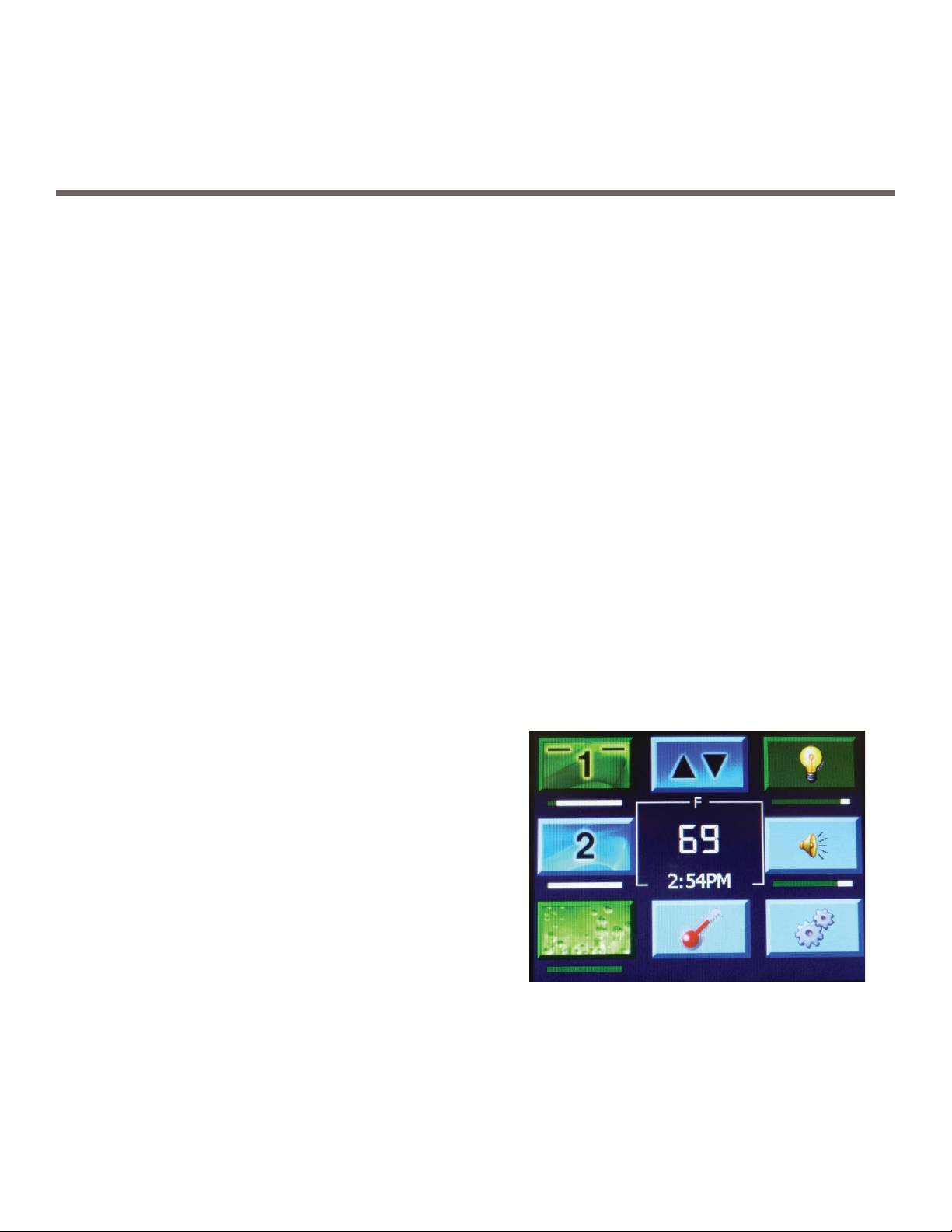
HOME SCREEN
The main screen will be referred to the “home” screen. The
on screen GUI shows icons. Shown counter clockwise are the
following icons, starting with the No. 1 pump: Pump 1, Pump 2,
Blower (optional Pump 3), Temperature, Setup, Audio, Lighting,
Inverse Screen.
Use the “pump 1”, “pump 2”, or “blower” buttons to UÊ
activate the desired component.
a) If the button is blue, it means the component is off.
b) If the button is green, it means that it is activated.
c) If the button turns red, that means there is some sort
of a problem associated with that component (low
current, blown fuse, disconnected, etc.)
d) If the area is blank, that equipment has not been
installed
Below the icons is a white status bar that appears, and UÊ
shows the amount of time used and that is left.
Center screen shows temperature in degrees Fahrenheit UÊ
(or Centigrade), and time. All conditions can be changed.
From any screen that allows for adjustments, a “Back” UÊ
button will take you to the previous screen.
At the bottom of the screen, a status is given of what is UÊ
occurring. For example “Circulating” may show.
Timing Status Bar Located Below Icons
Pump 1 timing is nearing end of time cycle.UÊ
Pump 2 is not activated.UÊ
Blower cycle has just turned on. UÊ
Light cycle has approx. 90% time left. UÊ
Audio cycle has approx. 80% time left.UÊ
5
Page 6

Operation Screens
PUMP AND BLOWER SETTINGS
Turn on Jet 1, Jet 2, and Blower by pressing the appropriate
button. If you have a two speed pump installed in Jet 1
position, the first press activates Jet 1, speed one; second
press activates Jet 1, speed two. The green button designates
ON. A red colored icon means that there’s a problem with the
equipment.
Two speed bars within the icon will position themselves High
or Low showing the speed selected.
SETTING THE TIME
Home > Setup > Time Set
Once inside the TIME SET screen, set the hour and minutes. Select
your preference. Then use the back button when you are finished.
To choose either standard time or military time, use the 12/24
button. To return to the Setup menu and save the time setting,
select the Back button. Note: In the case of a power failure, the
time will return to the 12PM default mode.
BLOWER
The settings for the Blower are: ON and OFF. The ON color is
Green. The OFF color is blue.
ICON COLORS AND SPEED BARS
PUMP 2,
LOW SPEED
PUMP 2,
HIGH SPEED
PROBLEM
WITH PUMP 1
6
Page 7

MAINTENANCE SCREEN
TEMPERATURE SELECTION
Home > Setup > Maint
The Maintenance screen allows you to program how many
days before maintenance reminders show up.
Within the Maint screen, choose the Reminder by using the
up and down arrows, and then how many days before the
Reminder will show up. Press the Save button. When finished,
use the Back button to exit.
Home > Setup > Temperature > Select [Set Temp]
To adjust the water temperature of your spa, access the
temperature setting screen. Select the Temp button on the
home menu screen.
To select the desired water temperature of your spa, press the
Up or Down arrows. To return to the home menu, select the
Back button.
Water temperature is maintained to +/- 1 degree of the set point.
When the water reaches the set point plus one degree, the heater
will shut off. When the water drops to 1 degree below the set
point, the heater will turn back on. Whenever there is a need for
heat, the system will conduct a FLOW TEST prior to turning the
heater on. This test runs approximately 1 minute, during
which this time no pumps can be controlled from the touch
screen menu. If the test is successful, the heating pump will
turn on.
7
Page 8

STATUS SCREEN
LOCKING THE DISPLAY SCREEN
Home > Setup > Data
The Status screen provides a quick way to view information on
the spa water temperature, flow rate, frequency, current, and
voltage.
Home > Setup > Lock/Unlock
Locking the display screen deactivates all of the buttons on
the display, so that nothing is unintentionally activated or
changed. Once locked, the screen will instantly go to screen
saver.
To unlock the display screen, press on the screen (if screen
saver is active), the Setup menu screen appears. The Button
that was previously “Lock” is now “Unlock.” Press Unlock,
and then press the Back button.
8
Page 9

TEMPERATURE UNITS SETTING
FILTRATION SETTINGS
Home > Setup > Temperature > Select [Temp Units]
To have your temperature display in Celsius or Fahrenheit,
activate Temp Units by using the Temp button. Then use the
arrows to toggle between F or C. Once the preference is made,
use the Back button to go Home.
SCREENSAVER
The screensaver activates after approximately 10 minutes of
no user interaction. A blank white screen will appear.
INVERTING THE DISPLAY
Inverting the display screen allows you to adjust the menus
easily whether you are in or out of your spa. To invert the display,
select the “INVERT” button on the main menu screen.
Home > Setup > Filter
The filtration cycles, duration, and start and stops times are
adjusted within the Filtration Screen. Once within the screen,
scroll to choose the start time. Press On/Off to turn the cycle
on. Scroll to the desired stop time, then press On/Off for the
stop cycle time. Repeat for additional filter cycles.
To review your filtration settings, scroll through the screen
using the Up and Down arrows and observe at what times
the filtration times are scheduled to turn on and off. To clear
the menu, press Clear All. To set filtration at 24 hours, select
Select All.
9
Page 10

VACATION MODE & ECONOMY MODE
Home > Setup > Econ/Vac
Green is activated; blue is off.
Economy Mode: Economy mode simply sets the UÊ
temperature back by 20°F as long as it is on.
Vacation days overtake the Economy setting. UÊ Once the
vacation set time has expired, the spa will return to the
settings previously set prior to activating. If you plan to
use the spa soon after returning home, set the number
of days to one less than you will be gone so that the
spa temperature will be back to normal by the time you
plan to return.
Vacation Mode: Vacation mode does the same thing except UÊ
that you can select the number of days for the setback.
Daily Button: Daily only has an effect when in Economy UÊ
mode. It repeats the economy cycle every day instead of
just once. You can set the number of hours that economy
mode will run from the time that the mode was set. After
that it will add the 20° back.
The Daily button doesn’t affect the filtration setting.UÊ
10
Page 11

Accessories and Optional Modules
Attention: Audio and LED Lighting require modules for operation. Be sure that the system is powered down completely before
removing or inserting any modules into the system. If the system is still powered up while removing or inserting any module,
irreparable damage may occur to the module, the mother board, or the panel.
AUDIO
Home > Audio
The Speaker icon takes you directly to the Audio screen.
Press On/Off to activate the audio system. The button is green
when activated. Press again to turn off the audio. The On/Off
button is blue when the audio system is Off.
Use the FM/MP3 button to choose between FM radio or UÊ
an MP3 Player.
If UÊ FM is chosen, then the Tune/Bass button allows you to
select a radio station.
To adjust the volume, use the up and down arrows. UÊ
Return to the home menu screen by selecting the UÊ
Back button.
LED LIGHTING
Home > Lighting
The Light Bulb icon takes you directly to the Lighting screen.
Press On/Off to activate the lighting system. The button is
green when activated. Press again to turn off the lights. The
button is blue when the lighting system is Off.
Use the up/down buttons to choose the color or light patterns
from the scrolling Color menu.
If Music is chosen, then the light synchronizes with the music.
To adjust the intensity of the lighting, select the Dimmer up/
down buttons.
Return to the home menu screen by selecting the Back button.
11
Page 12

LM8 CONTROL MODULES
The Red Control Module manages all Logic Functions:
Keeps time of day1.
Reports water temperature2.
Saves settings in flash memory3.
Translates messages from Touchscreen and activates Relay Board4.
Times out Pumps, Lights, and Audio5.
Safely maintains Heater Function6.
Monitors 7. Sensor Health
Backup Processor also watches for Heater or Sensor problems8.
The Yellow / Green LED Module provides colors and intensity selected
at Topside.
The Green Audio Module tunes FM from Topside Commands and
delivers 100W of Music.
Blank green modules are placeholders.
NOTE ON CHANGING COMPONENTS
When changing modules or panels, be sure that
the system is powered down completely before
removing or inserting any modules or panels
into the system. If the system is still powered up
while removing or inserting any module or panel,
irreparable damage may occur to the module, the
mother board, or the panel.
Panel Balboa LM8, Part No. 57126-03
12
57139 Board Balboa LM8000 LR6
Blank Module
Dark Green / Dark Green
Part No. 35006-G
Audio Sub Module
Lime Green / Lime Green
Part No. 57141
LM LED Sloan 2X Module
Yellow / Lime Green
Part No. 57143
Balboa Control Module LEIMFG
Part No. 57130-01
Page 13

Index
Symbols
3, optional Pump 5
A
Adequate drainage 2
Audio Module 12
B
Balboa Control Module LEIMFG 12
Blank Module 12
blank white screen 9
box, house breaker 2
breaker, Main Power 2
C
CE 4
Celsius 9
Changing Control Modules 12
changing modules 12
child lockout 4
Class A GFCI 2
clear 9
Clear All 9
codes 2
controlled, no pumps can be 7
CSA 4
cycles, filtration 9
D
diagnostics, Self-testing 4
Dimmer 11
display is locked 5
display, unlock the 8
drainage, Adequate 2
G
GFCI, Class A 2
Green Audio Module 12
H
heater will also be forced off 5
hours, filtration at 24 9
house breaker box 2
I
icon, Light Bulb 11
instructions, power connection 2
irreparable damage may occur 12
L
LEIMFG, Balboa Control Module 12
Light Bulb icon 11
locked, display is 5
Locking the display screen 8
lockout, child 4
Lock Spa 4
M
Main Power breaker 2
manual reset 5
military time 6
Module, Audio 12
Module, Blank 12
Module, Green Audio 12
Module, Red Control 12
modules, changing 12
Module, Yellow LED 12
Module, Yellow Sloan LED 12
Music 11
R
Red Control Module 12
Redundant connections 4
reset, manual 5
S
saver, screen 8
screen, blank white 9
Screen, Filtration 9
screen, Locking the display 8
screen saver 8
screensaver 9
Selection, Temperature 7
Self-testing diagnostics 4
Sensor Health 12
set point 7
set temperature 5
Setting, Temperature Units 9
Setting the Time 6
Sloan lighting systems 4
stale water 4
standard time 6
start time 9
T
temperature, set 5
Temperature Units Setting 9
TEST, FLOW 7
Test the ground fault circuit interrupter 2
timed out 5
time, military 6
Time, Setting the 6
time, standard 6
time, start 9
E
Econ/Vac 10
F
Fahrenheit 9
filtration at 24 hours 9
filtration cycles 9
Filtration Screen 9
flow test 4
FLOW TEST 7
freezing 5
N
NEC (National Electrical Code) 2
no pumps can be controlled 7
O
optional Pump 3 5
P
power connection instructions 2
pumps are shut down 5
purge stale water 5
U
UL 4
unlock the display 8
W
Warning, End User 2
Y
Yellow LED Module 12
13
Page 14

Tustin, Ca. 92780 (714) 384-0384
14
42193-A August 10, 2012
 Loading...