

Page 1
BAKERS
PRIDE
30 Pine Street • New Rochelle • New York • 10801
914 / 576 - 0200
914 / 576 - 0605
1 - 800 - 431 - 2745
www.bakerspride.com
l
l
l
I
I
I
F
F
F
fax
US & Canada
web address
n
n
n
r
r
r
o
o
o
o
o
o
DESIGN & INSTALLATION
GUIDELINES
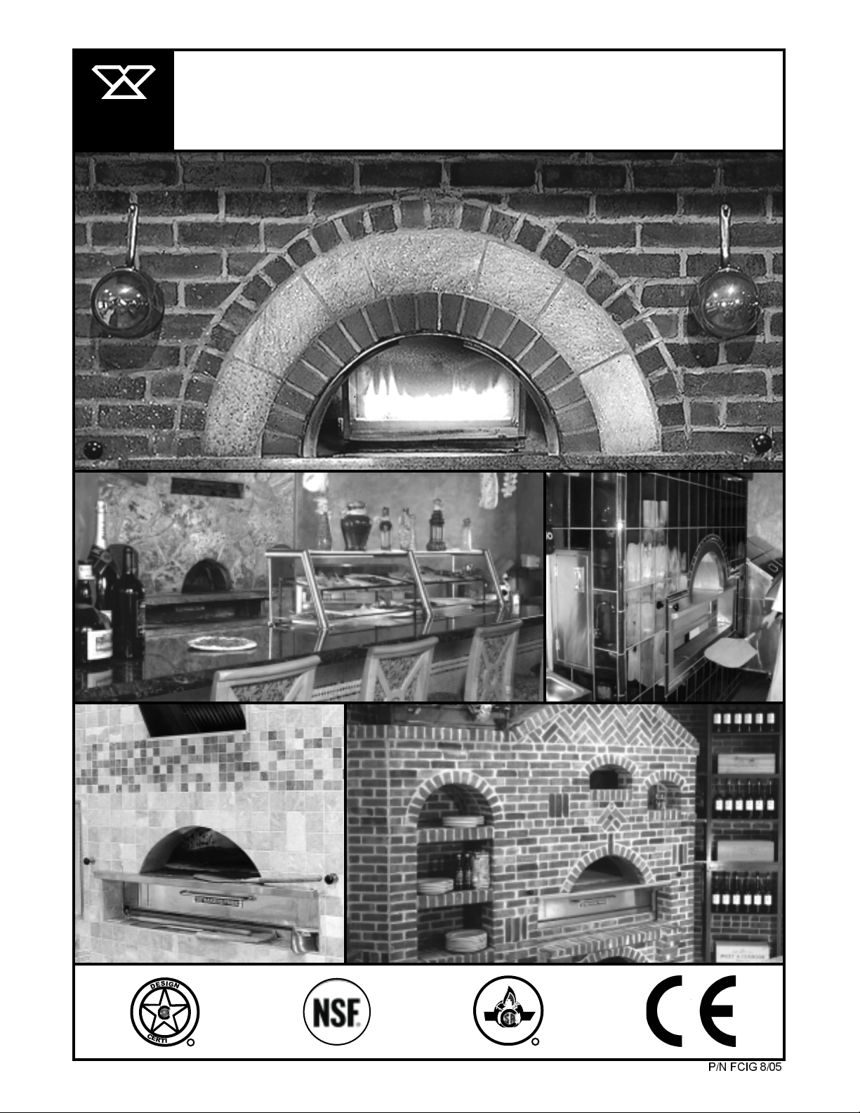
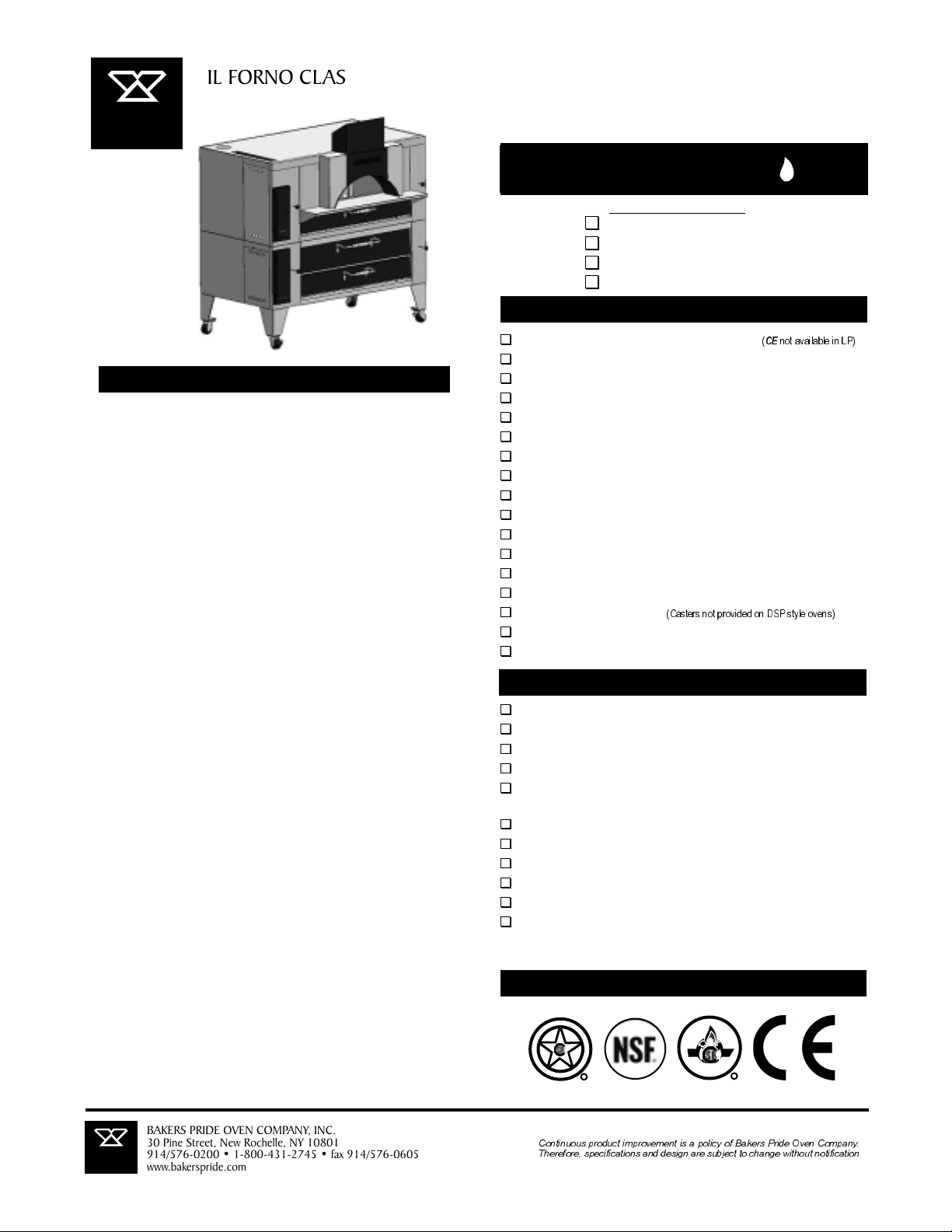
IL FORNO CLASSICO
MODELS: FC-516, FC-616 AND FC-816
C
C
C
l
l
l
a
a
a
s
s
s
s
s
s
i
i
i
c
c
c
o
o
o
I
G
S
N
E
D
C
E
D
R
E
I
T
I
F
R
1
CERTIFIED
R
P/N FCIG 8/05
Page 2
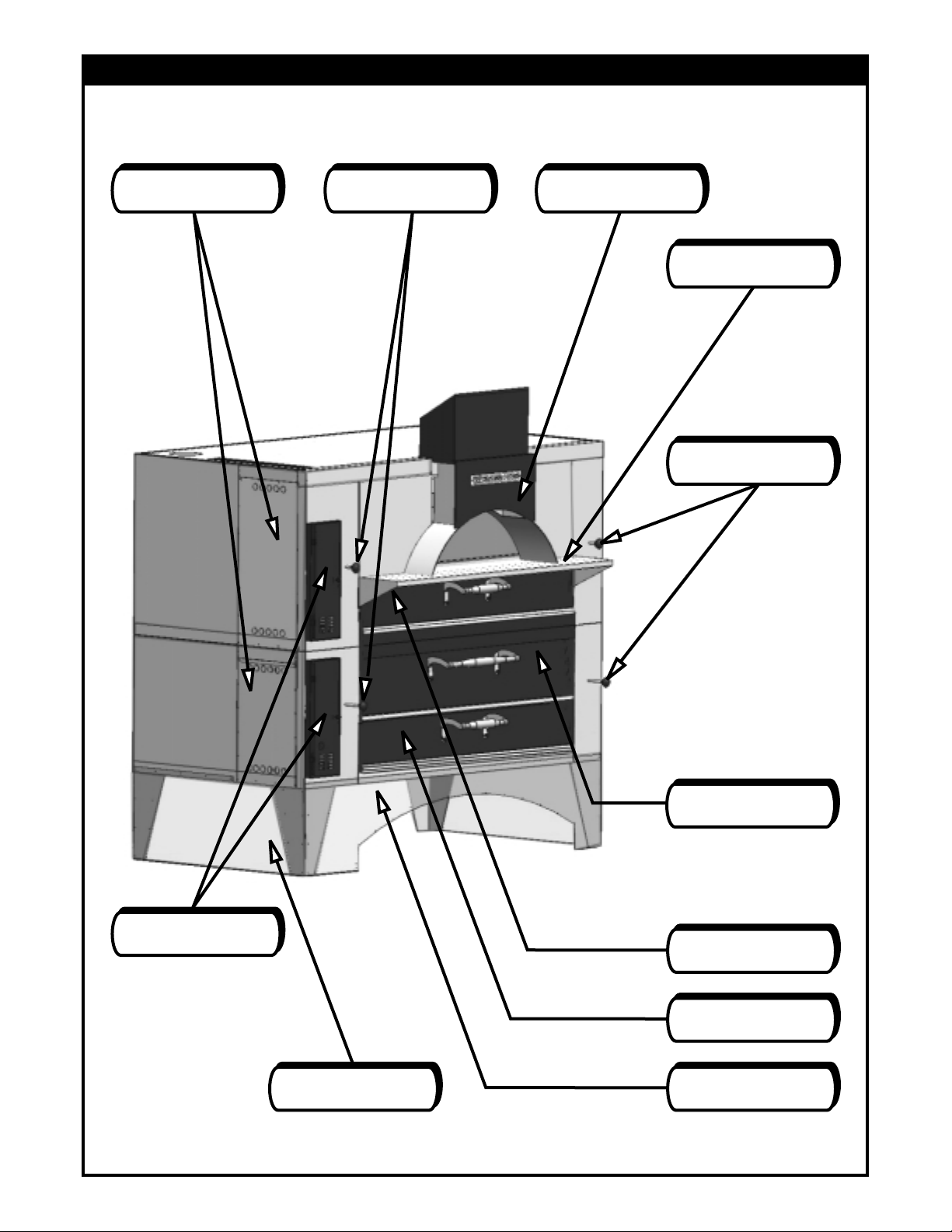
FC-616 Stacked On Y-600
DSP STYLE WITH SKIRTS
Side Access Covers
Push-Pull Rod Knobs
Removable Flue Cover
Lintel Plate/Plate Shelf
Push-Pull Rod Knobs
Hinged Control
Panel Doors
Side Skirt
Bake Chamber Door
Upper Combustion
Chamber Door
Lower Combustion
Chamber Door
Front Skirt
2
Page 3

TABLE OF CONTENTS
ITEM SKETCH PAGE
SPECIFICATION / ORDER GUIDE CHECK LIST 4
SPECIFICATION SHEETS 5-8
!
Single Ovens 5, 6
!
Double Ovens 7, 8
GETTING STARTED 1-4 9-12
PLAIN 'AS IS' 513
DECORATIVE-TRIM INSTALLATION GUIDELINES 6 13
“DSP” STYLE INSTALLATION GUIDELINES 7, 8 14
TRADITIONAL INSTALLATION INSTRUCTIONS 15-30
General Instructions (Building a Facade) 9 15
!
Ventilation of an Architecturally Enclosed Gas Fired Oven 10 16, 17
!
Ventilation, Air Supply & Fire Protection 11, 12, 13 18-21
!
Single Unit with Front Mounted Controls 14 22, 23
!
Single Unit with Side Mounted Controls 15 24, 25
!
Double Unit with Front Mounted Controls 16 26, 27
!
Double Unit with Side Mounted Controls 17 28, 29
!
Recommended Rear Clearances All Models 18 30
!
3
Page 4
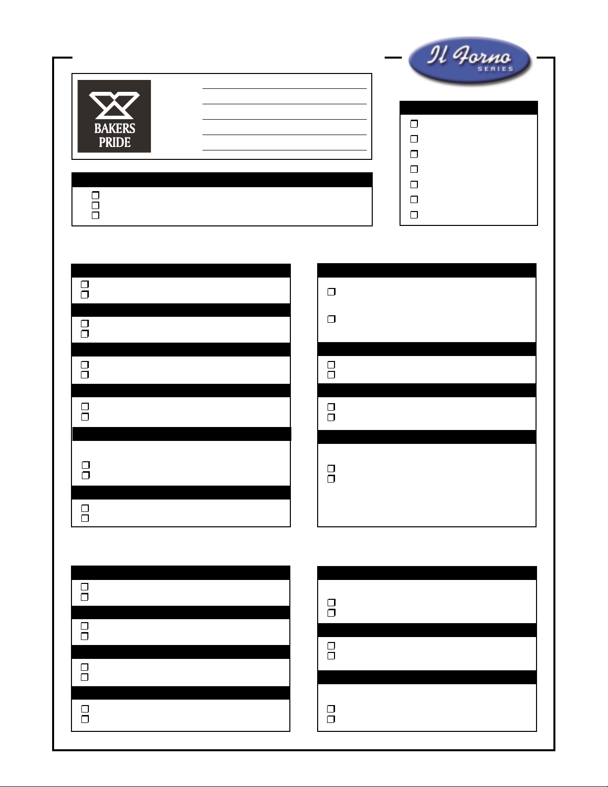
SPECIFICATION / ORDER GUIDE CHECK LIST
Date:
Dealer Name:
Project Name:
P. O. Number:
Signature:
How do you intend to finish/build-in your oven(s)? (Choose One)
As Is / Decorative Exterior Trim
DSP Style - Apply tile/stone directly on to oven(s)
Traditional - Building a facade/enclosure
Il Forno Specification/Order Check List
MODEL (Choose One)
FC-516 Single
FC-616 Single
FC-816 Single
FC-516/D-125 Double
FC-516/DS-805 Double
FC-616/Y-600 Double
FC-816/Y-800 Double
Hinged Control Panel Door (Choose One)
Front Mounted
Side Mounted
Hinged Control Panel Door (Choose One)
Black Powder Coated
Stainless Steel
Lower Combustion Chamber Door (Choose One)
Black Powder Coated
Stainless Steel
Removable Flue Cover (Choose One)
Black Powder Coated
Stainless Steel
Automatic Oven Starter (Optional)
Allows operator to establish automatic oven start & stop times
Yes
No
Brick Lining (Highly Recommended)
Yes
No
Lower Oven Of Stacked Installation Specification/Order Check List
Lintel Plate/Plate Shelf (Choose One)
Provided by customer to cover with tile, stone,
etc. (1” lower than cook/bake surface)
Covered by factory in stainless steel ready to
use (same height as cook/bake surface)
Gas Type (Choose One)
Natural Gas
L.P. Gas
Electric Type (Choose One)
115 volts, AC
240 volts, AC
Casters (Set of 4)
Not suitable for DSP style finish with skirts
Yes
No
Hinged Control Panel Door (Choose One)
Front Mounted
Side Mounted
Hinged Control Panel Door (Choose One)
Black Powder Coated
Stainless Steel
Lower Combustion Chamber Door (Choose One)
Black Powder Coated
Stainless Steel
Bake Chamber Door (Choose One)
Black Powder Coated
Stainless Steel
NOTE: See specification sheets for additional options & accessories.
Automatic Oven Starter (Optional)
Allows operator to establish automatic oven start & stop times
Yes
No
Gas Type (Choose One)
Natural Gas
L.P. Gas
Casters (Set of 4)
Not suitable for DSP style finish with skirts
Yes
No
4
Page 5
BAKERS
PRIDE
SPECIFICATION SHEETS
IL FORNO CLASSICO
Job ____________ Item # ___________
GAS DECK OVENS
G
SINGLE DECK MODELS
Model FC-516
Model FC-616
Model FC-816
STANDARD FEATURES
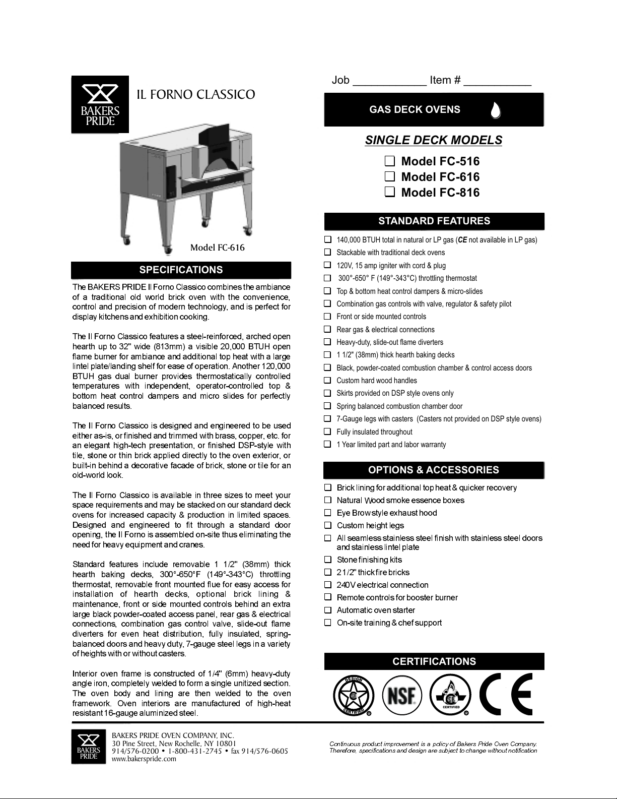
Model FC-616
SPECIFICATIONS
The BAKERS PRIDE IlForno Classico combines the ambiance
of a traditional old world brick oven with the convenience,
control and precision of modern technology, and is perfect for
display kitchens and exhibition cooking.
The Il Forno Classico features a steel-reinforced, arched open
hearth up to 32" wide (813mm) a visible 20,000 BTUH open
flame burner for ambiance and additional top heat with a large
lintel plate/landing shelf for ease of operation. Another 120,000
BTUH gas dual burner provides thermostatically controlled
temperatures with independent, operator-controlled top &
bottom heat control dampers and micro slides for perfectly
balanced results.
The Il Forno Classico is designed and engineered to be used
either as-is, or finished and trimmed with brass, copper, etc. for
an elegant high-tech presentation, or finished DSP-style with
tile, stone or thin brick applied directly to the oven exterior, or
built-in behind a decorative facade of brick, stone or tile for an
old-world look.
The Il Forno Classico is available in three sizes to meet your
space requirements and may be stacked on our standard deck
ovens for increased capacity & production in limited spaces.
Designed and engineered to fit through a standard door
opening, the Il Forno is assembled on-site thus eliminating the
need forheavy equipment and cranes.
Standard features include removable 1 1/2" (38mm) thick
hearth baking decks, 300°-650°F (149°-343°C) throttling
thermostat, removable front mounted flue for easy access for
installation of hearth decks, optional brick lining &
maintenance, front or side mounted controls behind an extra
large black powder-coated access panel, rear gas & electrical
connections, combination gas control valve, slide-out flame
diverters for even heat distribution, fully insulated, spring-
balanced doors and heavy duty, 7-gauge steel legs in a variety
of heightswith or without casters.
Interior oven frame is constructed of 1/4" (6mm) heavy-duty
angle iron, completely welded to form a single unitized section.
The oven body and lining are then welded to the oven
framework. Oven interiors are manufactured of high-heat
resistant 16-gauge aluminized steel.
with casters.
140,000 BTUH total in natural or LP gas
( not available in LP gas)CE
Stackable with traditional deck ovens
120V, 15 amp igniter with cord & plug
300°-650° F (149°-343°C) throttling thermostat
Top & bottom heat control dampers & micro-slides
Combination gas controls with valve, regulator & safety pilot
Front or side mounted controls
Rear gas & electrical connections
Heavy-duty, slide-out flame diverters
1 1/2" (38mm) thick hearth baking decks
Black, powder-coated combustion chamber & control access doors
Custom hard wood handles
Skirts provided on DSP style ovens only
Spring balanced combustion chamber door
7-Gauge legs with casters (Casters not provided on DSP style ovens)
Fully insulated throughout
1 Year limited part and labor warranty
OPTIONS & ACCESSORIES
Brick lining foradditional top heat & quicker recovery
Natural Wood smoke essence boxes
Eye Brow style exhaust hood
Custom height legs
All seamless stainless steel finish with stainless steel doors
and stainless lintel plate
Stonefinishing kits
2 1/2"thick fire bricks
240V electrical connection
Remote controls for booster burner
Automatic oven starter
On-site training &chef support
CERTIFICATIONS
I
G
S
N
E
D
C
E
D
R
E
I
T
I
F
R
CERTIFIED
R
BAKERS
PRIDE
BAKERS PRIDE OVEN COMPANY, INC.
30 Pine Street, New Rochelle, NY 10801
914/576-0200 • 1-800-431-2745 • fax 914/576-0605
www.bakerspride.com
Continuous product improvement is a policy of Bakers Pride Oven Company.
Therefore, specifications and design are subject to change without notification
3
5
Page 6
A
D
E
B
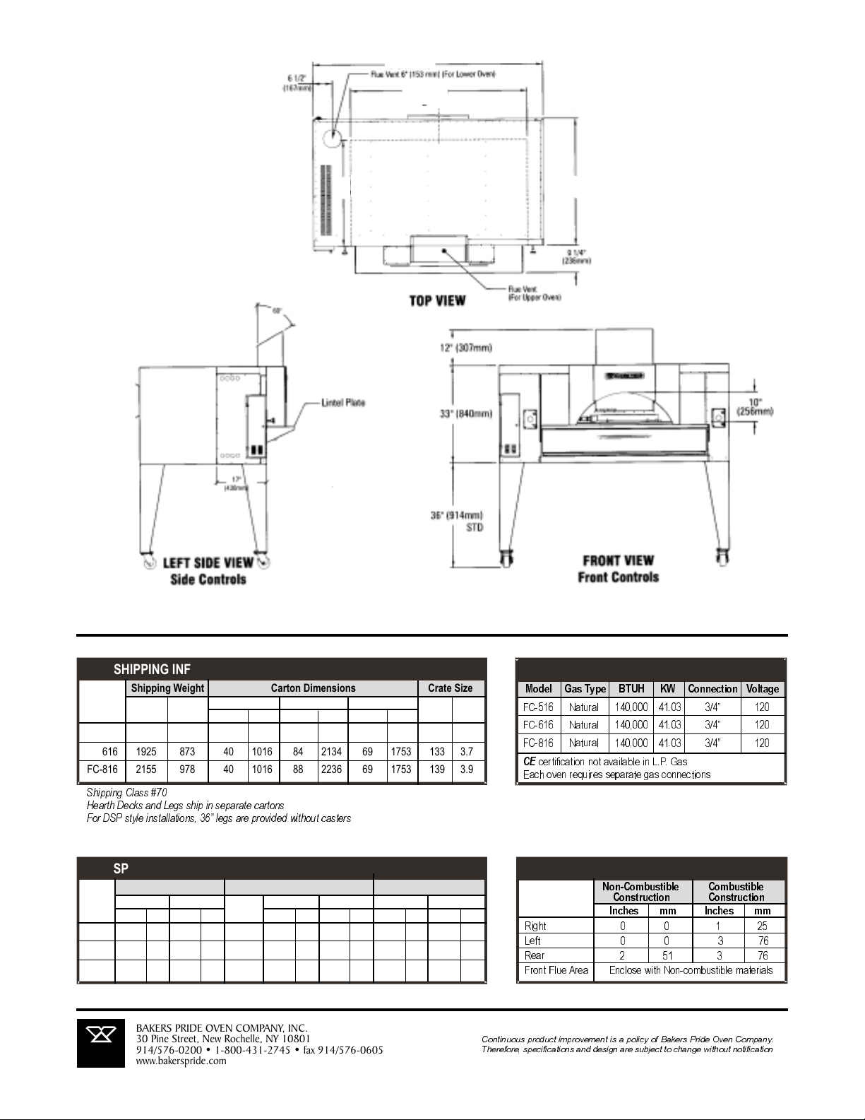
ALL DIMENSIONS NOMINAL
SHIPPING INFORMATION
Shipping Weight Carton Dimensions Crate Size
Model Lbs. Kilos Inches mm Inches mm Inches mm Feet Meter
FC-516 1588 720 40 1016 74 1880 62 1575 105 3.0
FC-616 1925 873 40 1016 84 2134 69 1753 133 3.7
FC-816 2155 978 40 1016 88 2236 69 1753 139 3.9
Shipping Class #70
Hearth Decks and Legs ship in separate cartons
For DSP style installations, 36 legs are provided without casters
SPECIFICATIONS
Oven Deck Arched Opening
Model Inches mm Inches mm Decks Inches mm Inches mm Inches mm Inches mm
FC-516 64 1/4 1657 43 1092 1 48 1219 36 914 24 610 10 254
FC-616 78 1981 43 1092 1 60 1524 36 914 32 810 10 254
FC-816 84 2134 51 1295 1 66 1676 44 1118 32 810 10 254
Width A Depth B # Width D Depth E Width Height
BAKERS PRIDE OVEN COMPANY, INC.
BAKERS
PRIDE
30 Pine Street, New Rochelle, NY 10801
914/576-0200 • 1-800-431-2745 • fax 914/576-0605
www.bakerspride.com
Width Depth Height Cubic Cubic
POWER SUPPLY
Model Gas Type BTUH KW Connection Voltage
FC-516 Natural 140,000 41.03 3/4 120
FC-616 Natural 140,000 41.03 3/4 120
FC-816 Natural 140,000 41.03 3/4 120
CE
certification not available in L.P. Gas
Each oven requires separate gas connections
MINIMUM CLEARANCES
Non-Combustible Combustible
Construction Construction
Inches mm Inches mm
Right 0 0 1 25
Left 0 0 3 76
Rear 2 51 3 76
Front Flue Area Enclose with Non-combustible materials
Continuous product improvement is a policy of Bakers Pride Oven Company.
Therefore, specifications and design are subject to change without notification
4
6
Page 7
IL FORNO CLASSICO
BAKERS
PRIDE
Model FC-616/Y-600DSP
with optional casters
SPECIFICATIONS
The BAKERS PRIDE II Forno Classico combines the ambiance of a
traditional old world brick oven with the convenience, control and
precision of modern technology, and is perfect for display kitchens and
exhibition cooking.
The IIForno Classico features steel-reinforced, archedopen hearth up
to 32" wide (813mm) witha visible 20,000 BTUH open flame burner for
ambiance and additional top heat with a large lintel plate/landing shelf
for easeof operation.Another 120,000 BTUH gas dualburner provides
thermostatically controlled temperatures with independent. operatorcontrolled top & bottorn heat control dampers and micro slides for
perfectly balanced results.
The IlForno Classico is designed andengineered to be used eitherasis, or finished and trimmed with brass, copper, etc. for an elegant hightech presentation, or finished DSP-style with tile, stone or thin brick
applied directly to the oven exterior, or built-in behind a decorative
facade of brick,stone ortile for anold-world look.
The II Forno Classico is available in three sizes to meet your space
requirements and may be stacked on our standard deck ovens for
increased capacity & production in limited spaces. Designed and
engineered to fit through a standard door opening, the II Forno is
assembled on-site thus eliminating the need for heavy equipment and
cranes.
Standard features include removable 1 1/2" (38mm) thick hearth
baking decks, 300°-650°F (1490 -343°C) throttling thermostat.
removable front mounted flue for easy access for installation of hearth
decks, optional brick lining & maintenance, front or side mounted
controls behindan extra large black powder-coated access panel, rear
gas & electrical connections, combination gas control valve, slide-out
flame diverters for even heat distribution, fully insulated, springbalanced doors and heavy duty, 7 -gauge steel legs in a variety of
heights with orwithout casters.
Interior ovenframe is constructed of 1/4"(6mm) heavy-duty angle iron,
completely welded to form a single unitizedsection. Theoven bodyand
lining are then welded to the oven framework. Oven interiors are
manufactured of high-heatresistant 16-gaugealuminized steel.
Job ____________ Item # ___________
GAS DECK OVENS
DOUBLE DECK MODELS
G
Model FC-516/ D-125
Model FC-516 / DS-805
Model FC-616/ Y-600
Model FC-816 / Y-800
STANDARD FEATURES
Up to 265,000 BTUH total in natural or LP gas
Stackable with traditional deck ovens
120V, 15 amp igniter with cord & plug
300° -650° F (149°-343°C) throttling thermostat
Top & bottom heat control dampers & micro-slides
Combination gas controls with valve, regulator & safety pilot
Side or front mounted controls
Rear gas & electrical connections
Heavy-duty, slide-out flame diverters
1 1/2" (38mm) thick hearth baking decks
Black, powder-coated combustion chamber & control access doors
Custom hard wood handles
Skirts provided on DSP style ovens only
Spring balanced combustion chamber door
7 -Gauge legs with casters
(Casters not provided on DSP style ovens)
Fully insulated throughout
1 Year limited part and labor warranty
OPTIONS & ACCESSORIES
Brick lining for additional top heat & quicker recovery
Natural Wood smoke essence boxes
Eye Brow style exhaust hood
Custom height legs
All seamless stainless steel finish with stainless steel doors
stainless lintel plate
Stone finishing kits
2 1/2" thick fire bricks
240V electrical connection
Remote controls for booster burner
Automatic oven starter
On-site training & chef support
CERTIFICATIONS
I
G
S
N
E
D
C
E
D
R
E
I
T
I
F
R
CERTIFIED
( not available in LP)
CE
R
and
BAKERS
PRIDE
BAKERS PRIDE OVEN COMPANY, INC.
30 Pine Street, New Rochelle, NY 10801
914/576-0200 • 1-800-431-2745 • fax 914/576-0605
www.bakerspride.com
Continuous product improvement is a policy of Bakers Pride Oven Company.
Therefore, specifications and design are subject to change without notification
7
Page 8
A
D
E
B
F
G
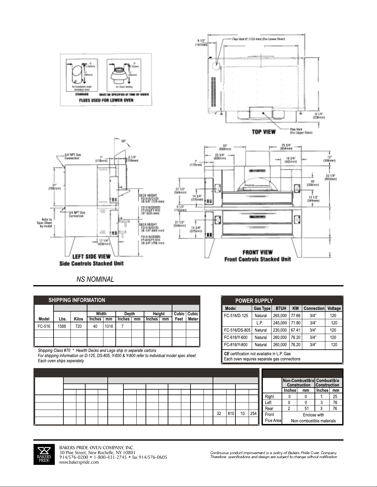
ALL DIMENSIONS NOMINAL
SHIPPING INFORMATION
Shipping Weight Carton Dimensions Crate Size
Model Lbs. Kilos Inches mm Inches mm Inches mm Feet Meter
FC-516 1588 720 40 1016 74 1880 62 1575 105 3.0
FC-616 1925 873 40 1016 84 2134 69 1753 133 3.7
FC-816 2155 978 40 1016 88 2236 69 1753 139 3.9
Width Depth Height Cubic Cubic
SPECIFICATIONS
Oven Deck Arched Opening
Model Inches mm Inches mm Decks Inches mm Inches mm Inches mm Inches mm Inches mm Inches mm
FC-516/D-125 64 1/4 1657 43 1092 2 48 1219 36 914 29 737 12 305 24 610 10 254
FC-516/DS-805 25 635 16 407 24 610 10 254
FC-616/Y-600
FC-816/Y-800 84 2134 51 1295 2 66 1676 44 1118 25 635 16 407 32 810 10 254
BAKERS
BAKERS
PRIDE
PRIDE
Width A Depth B # D E F G Width Height
64 1/4 1657 43 1092 2 48 1219 36 914
78 1981 43 1092 2 60 1524 36 914 25 635 16 407
BAKERS PRIDE OVEN COMPANY, INC.
BAKERS PRIDE OVEN COMPANY, INC.
30 Pine Street, New Rochelle, NY 10801
30 Pine Street, New Rochelle, NY 10801
914/576-0200 • 1-800-431-2745 • fax 914/576-0605
914/576-0200 • 1-800-431-2745 • fax 914/576-0605
www.bakerspride.com
www.bakerspride.com
Continuous product improvement is a policy of Bakers Pride Oven Company.
Continuous product improvement is a policy of Bakers Pride Oven Company.
Therefore, specifications and design are subject to change without notification
Therefore, specifications and design are subject to change without notification
POWER SUPPLY
MINIMUM CLEARANCES
8
Page 9
GETTING STARTED
Thank you for choosing a Bakers Pride Il Forno Classico oven. We recommend you thoroughly read and
consider steps #1 thru #7 prior to designing your kitchen and prior to ordering your oven(s). We also
recommend that you thoroughly read and understand these installation guidelines prior to installing your
new oven(s).
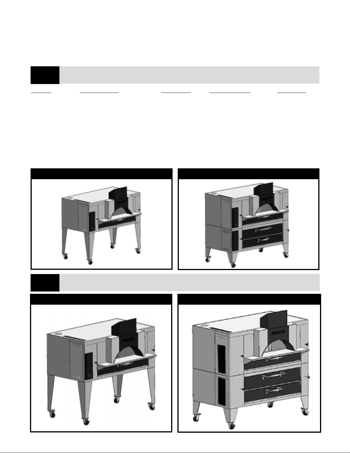
Step #1 Choose which oven size isright for you. Il Forno Classico is available in 3 sizes.
STEP #1
MODEL DESCRIPTION DECK SIZE NO. OF DECKS CAPACITY
FC-516 Single Deck Il Forno Oven 48” x 36” 1 4 each 16” Pizzas
FC-616 Single Deck Il Forno Oven 60” x 36” 1 6 each 16” Pizzas
FC-816 Single Deck Il Forno Oven 66” x 44” 1 8 each 16” Pizzas
FC-516/D-125 Il Forno stacked on D-125 48” x 36” 2 8 each 16” Pizzas
FC-516/DS-805 Il Forno stacked on DS-805 48” x 36” 2 8 each 16” Pizzas
FC-616/Y-600 Il Forno stacked on Y-600 60” x 36” 2 12 each 16” Pizzas
FC-816/Y-800 Il Forno stacked on Y-800 66” x 44” 2 16 each 16” Pizzas
Choose single, or double deck for increased capacity and production through put.
Refer to individual specification sheets for more details.
1A SINGLE DECK IL FORNO
Step #2 Choose front-mounted or side-mounted control panel(s). The exterior finish style and location of
STEP #2
controls often work together to create the “look” you want.
1B IL FORNO STACKED
2A SINGLE OVEN W/FRONT-MOUNTED CONTROLS 2B DOUBLE UNIT W/SIDE-MOUNTED CONTROLS
9
Page 10
Step #3 Decide how you intend to “finish” or “build-in” your oven(s) prior to ordering. Installation instructions
STEP #3
are available for each “finish” style. There are four basic styles: 1, 2, 3, 4.
3A PLAIN “AS-IS” - STYLE 1
Plain, AS-IS ready to use. No decorative finish.
Available with standard front or all stainless steel
exterior.
3C DSP - STYLE 3
3D TRADITIONAL - STYLE 4
3B DECORATIVE TRIM - STYLE 2
Finish your oven with decorative trim-pieces of
brass, copper, tile etc., in standard front or all
stainless steel exterior.
Skirts
“DSP” Style. Stone, tile, thin brick or
other masonry finish is applied
directly to the oven exterior. Skirts
provided, casters excluded.
Traditional - “built-in”. Involves building a facade over
the front, or front and side(s) or around all four sides.
The facade is finished in brick, stone, tile, marble or
materials of choice. Push-Pull rod extensions provided.
10
Page 11

Step #4 Ventilation: Choose either a canopy or eye-brow style hood. (DO NOT direct vent anIl Forno Classico).
STEP #4
4A
See pages 18-21
for ventilation
details.
Canopy Style Hood
4B
Eye-brow Style Hood
See pages 18-21
for ventilation
details.
Single Unit
Double Unit
NOTE: Minimum clearance may be reduced when using UL listed hood assemblies and installed in accordance with
the terms of the listing and the manufacturer instructions. Consult NFPA standard number 96 and local codes
concerning ventilation requirements and fire extinguishing system requirements.
11
Page 12

Step #5 Choose gas type: Natural or L.P. Gas.
STEP #5
STEP #6
Step #6 Choose electric type: 120V or 240V.
!
Step #7
STEP #7
!
!
!
!
!
!
!
!
!
Provision of 115 Volts AC, 15 Amps electric supply for the booster burner ignition control systems
must be made. (Optional 240VoltsAC available).
Choose options and accessories
Casters - Set of 4.
NOTE:
DO NOT
Brick lining - highly recommended for top heat intensity and quicker recovery.
Natural wood essence smoke boxes.
Automatic oven starter.
Remote controls for booster burner.
Combustion chamber door in stainless steel or black powder coated with hard wood handles.
Hinged control panel access door in stainless steel or black powder coated.
Removable flue cover in stainless steel or black powder coated.
Black powder coated doors and flue may be mixed or matched with stainless steel doors and flue on
special request.
Provision for restraints on the legs with casters must be made.
use casters with DSP style built-in ovens as the casters interfere with the skirts.
Other Key Provisions And Notes
!
!
!
Emergency gas shut off valve in an easily accessible location must be provided by the customer.
Units must be electrically grounded to conform to the National Electric Code ANSI/NFPA#70 and/or
local codes.
Gasoline or other flammable vapors and liquids should never be stored in the vicinity of the unit.
BE SPECIFIC WHEN ORDERING
12
Page 13

PLAIN “AS-IS” STYLE INSTALLATION
Your IL FORNO CLASSICO oven(s) may be used “asis” without decorative finishes or architecturally
designed facades. For best-looking results consider
your preference for stainless steel doors or black
powder coated doors with wood handles and other
exterior finish options.
Oven(s), decks and legs are shipped in separate
cartons. Uncrate, attach legs, install decks then
connect gas and electric utilities. Refer to operating
instruction manual for details .provided with oven(s)
DECORATIVE TRIM STYLE INSTALLATION
5 PLAIN “AS-IS” STYLE
Plain, AS-IS ready to use. No decorative finish.
Available with standard front or all stainless steel
exterior.
Rather than 'building-in' your oven(s) or applying
masonry finishes directly to the oven(s) exterior,
consider finishing your oven(s) with decorative trimpieces of brass, copper, powder-coated colored trim or
L-shaped tile pieces.
For best looking results, consider an all stainless steel
exterior finish. Control panel access cover,
combustion chamber door and flue-front may be
ordered in black-powder-coated finish or stainless
steel.
Metal trim pieces are fastened by the foodservice
equipment contractor directly to the oven exterior using
3/8” to 1/2” sheet metal screws. Pre-drill holes for best
results.
The design is only limited by your imagination.
Consider finishing the lintel plate with matching
materials, tile, stone or stainless steel. Stainless steel
lintel plate provided when ordering the all stainless
exterior option.
Disclaimers: Continuous product improvement is a policy of Bakers Pride. Therefore specifications and designs are
subject to change without notice. Ultimately, the proper design and execution of any appliance installation is the
responsibility of the property owner. That party or their representative is expected to engage the service of a qualified
professional to carry out that responsibility. This includes matters of compliance with local codes. The above
information is provided as guidelines to the installation professional. Job site conditions vary considerably, and
therefore Bakers Pride Oven Company can assume no responsibility or liability for the proper installation and
operation of the gas-fired appliance. The above assumes certain conditions, which are specified. A quality
professional may modify these recommendations as job site conditions dictate. For example, 70°F air is assumed.
6 DECORATIVE TRIM STYLE
Finished with decorative trim-pieces of brass,
copper, tile etc. In standard front or all stainless
steel exterior.
13
Page 14

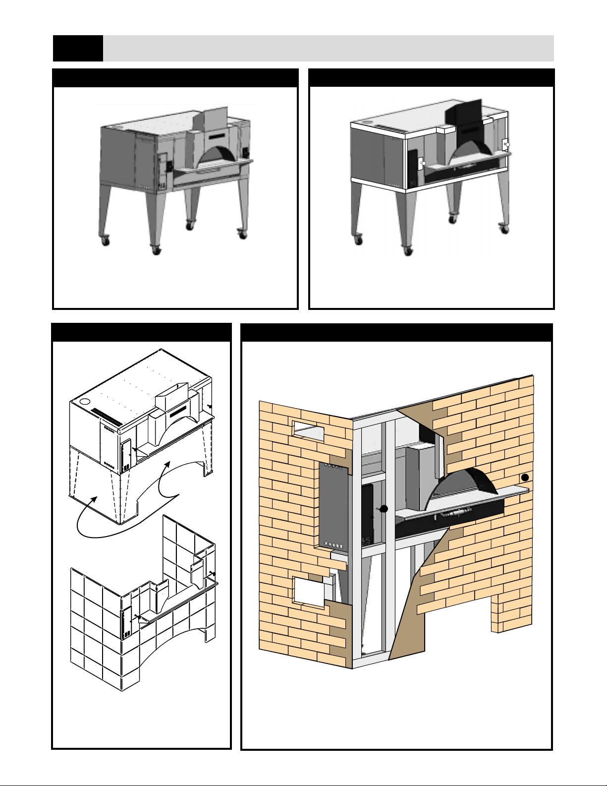
DSP STYLE INSTALLATION
Anyone with some experience laying tile should be able to complete this project with relative ease.
Step #1 Uncrate oven(s), set in place.
Step #2 Attach front sheet metal skirt (provided) by drilling holes in oven legs using pre-punched holes in sheet
metal skirt as a template.
NOTE:
Step #3 Secure skirt using sheet metal screws.
Step #4 If you plan on finishing the oven sides with tile, etc, follow steps #2 and #3 for side skirts.
Bottom flange on skirt faces outward.
Step #5 Fasten 3/8” thick fire resistant “Wonder Board” (7mm) to oven front (and sides if appropriate) using 1/2” to
5/8” sheet metal screws. When finishing Lintel Plate, thinner “Wonder Board” and shorter screws may be
necessary.
NOTE: “
Step #6 Attach tile, stone, thin-brick or the material of choice over “Wonder Board” using either a latex/polymer
based high-heat ceramic thin-set mortar, “spec” mix mortar or type “S” mortar. Best results will be achieved
using tile, etc. no more than 5/8” thick.
NOTE:
Step #7 Consider L-shaped tile or brick trim pieces along front vertical corners and top edges of oven front and side
to complete a finished look.
Step #8 Grout between brick joints. It is best to allow the thin-set mortar to dry over night prior togrouting.
Step #9 Allow grout to dry for 24 hours prior to starting ovens.
NOTE: Wonder Board equivilents; Harde Backer Board, various trade names.
Wonder Board” must be cut to fit. Allow access for push-pull rod holes, oven control access
doors and combustion and bake chamber doors.
Start at the floor and work up to top of oven. Cut stone, etc. to fit as required based on your design
and to create the look you want.
i
7 FC-616 DSP WITH TILEWORK
8 FC-616 STACKED ON Y-600 WITH TILEWORKDSP
14
Page 15

TRADITIONAL INSTALLATION
Building a Facade:
The facade may consist of a front only, front and one side, front and two sides or all four sides. Generally the facade is
framed with metal studs, then covered with fire-resistant “Wonder Board” and decorated with tile, brick, masonry or
material of choice. Check with local health department and building codes for local requirements.
Before Proceeding:
Note that provisions must be made in the facade for access to the control panel cover, push-pull rods, arched
opening, combustion chamber door(s), service panels and electrical and gas connections. Provisions must be made
for air movement in architecturally enclosed structures. Instructions on the following pages.
Step #1 Uncrate oven(s), set in place.
Step #2 Build a metal-stud frame. Work around your oven(s) allowing provisions for air movement and access
requirements (described on following pages).
Step #3 Fasten 3/8” (7mm) “Wonder Board” to oven metal-stud framework using sheet metal screws.
Step #4 Attach tile, stone, marble, thin brick or finish of your choice over Harde Backer Board using a latex/polymer
based high-heat resistant ceramic thin set mortar. Start at the floor and work up to the top of facade
enclosure. Cut tile, etc to fit as required based on your design and to create the look you want.
Step #5 Grout between tile/stone joints. It is best to allow thin set mortar to dry overnight prior to grouting.
Step #6 Allow grout to dry for 24 hours prior to starting oven(s).
9 BUILDING A FACADE
Helpful Hints
Control Panel Cover(s),
Thermostat(s) and
Service Panels:
Frame around Control
Panel Cover(s) with
metal studs. Studs may
be placed directly
against oven exterior.
Combustion Chamber
Door(s):
Leave Exposed for easy
access.
Push-Pull Rods:
Provide 1” or less
diameter holes in facade
so holes are covered by
push-pull rods.
Lintel Plate(s):
Leave lintel plates
exposed and cover lintel
plate with marble, tile, etc
for good looks and to
provide flush landing
shelf. (Lintel plate is 1”
lower than deck height).
NOTE: See DSP style
installation for lintel plate
finish instructions and
compensate as required.
Side Access Cover
Top Enclosure
Opening
Metal Studs
Wonder Board
Front Facade
(Brick, Tile, etc)
Push-Pull Rod
Openings
Lintel Plate
Baking Chamber
Access Opening
Combustion Chamber
Access Opening
Bottom Enclosure
Openings
Note: This illustration is intended as a general guide for facade construction. It is not intended to represent
specific layout & design but rather to convey the construction process. Dimensions are nominal-Not to scale.
15
Page 16

VENTILATION OF AN ARCHITECTURALLY ENCLOSED GAS FIRED OVEN
This applies to the FC series ovens initially, but also to FC “stacks” as well as any other enclosed installations. A four
walled “room” around the oven is anticipated, with a ventilation hood as the room’s “ceiling”.
(This four-walled room is selected for this discussion as an easily defined, “worst case” scenario. A more ideal
installation is enclosed on only one, two or three sides, which face the public space of the restaurant. The back and one
or two sides are open to the kitchen and/or other working spaces).
AIR VOLUME REQUIRED
The purpose of ventilation is to remove bi-products of combustion, remove grease laden vapors,limit thetemperatures
within the enclosure and to provide fresh air for combustion. The combustion air volume is included in the larger
volume required for temperature controlling the space, therefore only a single calculation is required.
VOLUME REQUIRED (CFM) = RATED INPUT (BTUH) / 105
e.g. The air required for an FC-816 stacked with aY-800is 2,476 CFM ( = 260,000 BTUH / 105 ).
This assumes: (1) 70°F air entering the enclosure, (2) the oven runs at an average of 70% of its rated input during peak
business hours and (3) 25% “stack losses” are discharged directly to the top of the enclosure or are removed from the
enclosure by a chimney connection.
AIR OPENINGS TO THE ENCLOSURE
At least three total openings must be provided in the enclosure to allow the oven within the enclosure to properly
breathe. Additional openings are acceptable.
manufacturer.If theratings are not known, assume 25% free area for wood louvers and60% free area for metal louvers
and grilles.
TOP OPENING(S)
At least one opening must be provided. The top opening(s) prevents pressure differences from developing over the
height of the enclosure. Provide an opening of one square inch free area per 1,000 BTUH of RatedInput:
Top Opening Free Area (sq in) = Rated Input (BTUH) / 1000.
e.g. The top opening for a FC-816 stacked with a Y-800 is 260 sq in (=260,000 BTUH / 1,000).
opening should be within (12”) twelve inches of the bottom edge of the ventilation hood.
BOTTOM OPENING(S)
At least one opening must be provided. The bottom opening(s) provides the bulk of the ventilation air to the space.
Enough area must beprovided to limit the entering air velocity to five feet per second. The calculation:
Bottom Opening Free Area (sq in) = Rated Input (BTUH) / 219
e.g. The bottom opening for an FC-816 stacked with aY-800is 1,187 sq in (=260,000 BTUH / 219).
The same discussion regarding louvers and grilles applies. The Bottom opening, or openings, should be planned to
distribute air uniformly about the lower portion of the enclosure. The bottom edge of the bottom opening (s) should be
within twelve inches of the floor of the enclosure.
Louvers and grilles typically have free area ratings provided by their
The top edge of this
CLEARANCES
Within the enclosure the normal clearances for safety and service should be maintained. Additionally the floor area of
the enclosure should be at least equal to the “footprint” area of the oven plus the Bottom Opening Free Area. This limits
the vertical air velocities inside the enclosure to the same five feet per second.
e.g. FC-816 stacked with Y-800......51” deep x 84” wide = 4,284 sq in
Add the bottom free area: 1,187 sq in (Roughly4 1/2” all around)
Total 5,471 sq in (38sq ft) [Roughly 60” x 93”]
16
Page 17

When building a 4-walled facade, or room aroundthe oven(s),provisions mustbe madein the facade/enclosure for the free and uninterupted air movement to the interior
of enclosed installations from the room outside the enclosure.
17
10
Sq in =
Input
219
CFM=
12” Max.
Input
105
AIR SUPPLY & VENTILATION
Models Enclosure Openings (Top) Enclosure Openings (Bottom)
FC-516/FC-616/FC-816 140 SQ.IN(903 SQ.cm)
FD-516/FY-616/FY-816 260 SQ. IN(1675 SQ.cm)
Sq in =
Input
1,000
640SQ. IN (4,130 SQ.cm)
1,187 SQ. IN (7,660 SQ.cm)
12” Max.
NOTE: Refer to instructions on previous page.
* OPENINGS
IL FORNO CLASSICO
* TYPICAL OPENINGS SHOWN FOR A COMPLETELY
OPENINGS OF OTHER SHAPES MAY BE PROVIDED AT ANY OTHER SUITABLE
LOCATION TO SERVE THE SAME PURPOSE.
ENCLOSED INSTALLATION.
Page 18

VENTILATION, AIR SUPPLY AND FIRE PROTECTION
All gas appliances must be ventilated. Proper air supply and ventilation is essential for effective operation. Consult
NFPA (National Fire Protection Association) standard number 96 as well as local mechanical codes concerning
ventilation requirements and potential fire extinguishing systems requirement in your area.
There are two basic methods for ventilating the IL FORNO CLASSICO; canopy style hood(s) or eye-brow style
hood(s). The ILFORNO CLASSICO should not be direct vented althoughthe loweroven ina stacked installation may
be direct vented.
Canopy Hood(s):
grease laden vapors. A Type II canopy is appropriate in most areas. Typically the canopy will extend beyond the
footprint of the oven(s) by 4 to6 inches (102mm to 150mm) and be at least 78” from the floor (1950mm).
The distance between the grease removal device and the cooking surface shall be as great as possible but not less
than 18” (458mm) and not greater than 30” (762mm), NFPA standard #96.
NOTE: Minimum clearance may be reduced when using UL listed hood assemblies and installed in accordance with
the terms of the listing and the manufacturer instructions. Consult NFPA standard number 96 and local codes
concerning ventilation requirements and fire extinguishing system requirements.
Low velocity hoods are recommended. High velocity hoods will pull too much heat from your oven(s) baking chamber
causing inconsistencies in bake/cook performance (not enough top-heat and too much bottom heat).
Eye-Brow Hood(s):
Bakers Pride offers two models of eye-brow style hoods: Model #PB-24 for single IL FORNO CLASSICO ovens and
model # PB-24S for IL FORNO CLASSICOstacked on D, DS or Y-Series deck ovens.
Refer to individual specification sheets for details. Hoods are shipped loose with mounting angle for installation by
foodservice equipment contractor.
Exhaust Fans:
effectively removing bi-products of combustion, grease-laden vaporsand heat from your kitchen.
Exhaust fans are required and provided and installed by others in compliance with local mechanical code.
A properly designed canopy hood will remove heat as well as bi-products of combustion and
Will remove bi-products of combustion, grease-laden vapors and most heat from your oven(s).
An exhaust fan is required for all ventilation types. The exhaust fan will create a vacuum thus
Low-velocity fans are recommended. High volume exhaust fans will pull too much heat from your oven(s) baking
chamber causing inconsistencies in bake/cook performance (not enough top-heat and too much bottom heat).
Fan sizing is determined by computing static air pressures at the hood entrance, the length of duct work (static
pressure drops) and CFMs required for your particular oven(s). Contact your hood manufacturer or H.V.A.C.
Contractor for specifications.
Air Supply
properly. For proper balance contact your local H.V.A.C. contractor.
Gas burners and pilot lights require sufficient air to operate properly. Do not place objectsover the oven vent exits and
do not obstruct airflow to the ovens by placing objects in the rear, underor in front of your oven(s).
For minimum air-flow requirements of architecturally enclosed ovens refer to the “Traditional Built-in” section of this
manual.
Make-up air must be supplied for replacement of air exhausted through all kitchen exhaust systems. Make-up air
should be delivered through registers at ceiling height and distributed throughout the kitchen 75% to 80% of
replacement air should be fresh, outside air, conditioned (heated or cooled) distributed directly into the kitchen with
the remaining 20% to 25% allowed to flow into the kitchen from adjacent areas.
Fire Protection: Contact your local fire officials and refer to local mechanical codes for exact requirements in your
area.
NFPA Standard No. 96 requires a fire extinguisher system for protection of the duct collar and plenum of nonwaterwash ventilators.
: Exhausted and make-up air must be properly balanced for your exhaust system and oven(s) to work
18
Page 19

11 AIR SUPPLY & VENTILATION (CANOPY STYLE HOOD)
For improved exhausting of heat,
ventilation hood (supplied by customer)
should extend at least 4” beyond
arched opening in the front.
4 (102mm)
VENTILATION HOOD
19
(SUPPLIED BY CUSTOMER)
SEE NOTE
1 1/4 (30mm)
32 ½ (827mm)
REF.
CANOPY
STYLE
HOOD
17 (432mm)
6 (153mm)
NOTE: Minimum clearance may be reduced when using UL listed hood
assemblies and installed in accordance with the terms of the listing
and the manufacturer instructions. Consult NFPA standard number 96
and local codes concerning ventilation requirements and fire
extinguishing system requirements.
Page 20

12 AIR SUPPLY & VENTILATION (MODEL PB-24 EYE-BROW HOOD)
No. 7 Mirror Finish
20
4 (102mm)
92 3/4 (2357mm)
Top of Ventilator
88 3/4 (2255mm)
A.F.F.
24 (608mm)
2 (51mm)
Stainless Steel Finish Back
No. 4 Finish
(1) Component Hardware
Firefighter Series
Baffle type Grease Filters
(1) 16”H x 20”W Filters
Model #F60-1620
UL Classified
1 ½”x 1 ½”S/S
Mounting Angle
12 (304mm)
Removable Grease Cup
NOTE: Consult NFPA standard number 96 and local codes concerning ventilation
requirements and fire extinguishing system requirements.
Page 21

13 AIR SUPPLY & VENTILATION (MODEL PB-24S EYE-BROW HOOD)
21
No. 7 Mirror Finish
4 (102mm)
98 1/4 (2495mm)
Top of Ventilator
94 1/4 (2393mm)
A.F.F.
24 (608mm)
2 (51mm)
Stainless Steel Finish Back
No. 4 Finish
(1) Component Hardware
Firefighter Series
Baffle type Grease Filter
16”H x 20”W
Model #F60-1620
UL Classified
6” Flue Connection
Flue Duct
By E.C. or other
prescribed contractor
1 ½”x 1 ½”S/S
Mounting Angle
12 (304mm)
Removable Grease Cup
NOTE: Consult NFPA standard number 96 and local codes concerning ventilation
requirements and fire extinguishing system requirements.
Page 22

SINGLE OVENS WITH FRONT MOUNTED CONTROLS
WHEN BUILDING YOUR FACADE, PROVISIONS MUST BE MADE FOR ACCESSING THE FOLLOWING:
(SEE SKETCH 14, PAGE 21)
FRONT:
1. Hinged control access panel
2. Push-pull rods (2)
3. Arched opening and lintel plate
4. Combustion chamber door
LEFT SIDE:
1. Side service access panel (optional & recommended). Access to this panel eases potential service
access to the valve, booster burner control, booster burner ignition module and thermostat. However
all components may be accessed though front hinged controls access panel (difficult).
REAR:
1. Rear booster burner, flame sensor and igniter - Provision should be considered for potential service
of these components. Following are 3 options:
A. Rear access panel (recommended).
B. Hinged or removable panel on the front of the facade to allow the removal of flue cover and
inserts. This provides greater access for a technician to service these components through
the front of the oven (see drawing below).
C. Through the arched bake chamber entrance (difficult).
2. Electrical connection
3. Gas connection
4. Minimum clearance for Service Technician and/or for safe operation
VENTILATION, AIR SUPPLY AND FIRE PROTECTION:
OPTION “B” ACCESS TO BOOSTER BURNER
ID
R
P
S
R
E
K
A
B
Insert
SEE INSTRUCTIONS ON PAGES 14-19.
E
Flue Cover
Insert
22
Lintel Plate
Page 23

14
SINGLE UNIT (WITH FRONT MOUNTED CONTROLS)
FC-516/DS-805/D125 65 1/4 (1657mm)
FC-616 78 (1981mm)
FC-816 84 (2134mm)
10 5/8 (269mm)
7 (179mm)
Hinged Control
Access Panel
21 ½ (546mm)
FC-516
3 3/4 (94mm)
FC-616/816
9 (229mm)
Push-Pull Knob
FC-516
3 3/4 (94mm)
FC-616/816
9 (229mm)
Flue
FC-516 15 ½ (395mm)
FC-616 16 3/4 (425mm)
FC-816 19 3/4 (502mm)
12 (306mm)
3½
(89mm)
Push-Pull
Knob
33 (838mm)
14 3/4 (375mm)
11 ½ (293mm)
(51mm)
38 (965mm)
20 3/4
(527mm)
Booster Burner
Access Cover
2
115VAC, 15A
NEMA 5-15P
FC-516 26 (660mm)
FC-616 32 (813mm)
FC-816 35 (889mm)
Line Cord
Arched Opening
FC-516 24 (610mm)
FC-616/816 32 (813mm)
Lintel Plate & Main Burner Access
FC-516 44 3/4 (1137mm)
FC-616/816 56 3/4 (1441mm)
Front View
1 3/4 (44mm)
3/4 NPT
Gas Inlet
31 (787mm)
1 (25mm)
12 (305mm)
3/4 NPT
Gas Inlet
30 3/4 (782mm)
36 (914mm)
Side
Access
Cover
9 7/8 (251mm)
6 7/8 (175mm)
1 1/4 (32mm)
1 1/4 (32mm)
52 (1320mm)
Rear View
115VAC, 15A
NEMA 5-15P
Line Cord
23
(430mm)
Left Side View
9 3/8 (237mm)
17
49 ½ (1257mm)
Deck Height
Page 24

SINGLE OVENS WITH SIDE MOUNTED CONTROLS
WHEN BUILDING YOUR FACADE, PROVISIONS MUST BE MADE FOR ACCESSING THE FOLLOWING:
(SEE SKETCH 15, PAGE 23)
FRONT:
1. Push-pull rods (2)
2. Arched opening and lintel plate
3. Combustion chamber door
LEFT SIDE:
1. Hinged control access panel
2. Side service access panel (optional). Access to this panel eases potential service access to the
valve, booster burner control, booster burner ignition module and thermostat, however all
components may be accessed though the side mounted hinged controls access panel.
REAR:
1.
2. Electrical connection
3. Gas connection
4. Minimum clearance for Service Technician and/or for safe operation
Rear booster burner, flame sensor and igniter - Provision should be considered for potential service
of these components. Following are 3 options:
A. Rear access panel (recommended).
B. Hinged or removable panel on the front of the facade to allow the removal of flue cover and
inserts. This provides greater access for a technician to service these components through
the front of the oven (see drawing below).
C. Through the arched bake chamber entrance (difficult).
SEE INSTRUCTIONS ON PAGES 14-19.VENTILATION, AIR SUPPLY AND FIRE PROTECTION:
OPTION “B” ACCESS TO BOOSTER BURNER
E
ID
PR
S
R
E
K
A
B
Flue Cover
Insert
Insert
Lintel Plate
24
Page 25

15
SINGLE UNIT (WITH SIDE MOUNTED CONTROLS)
FC-516/DS-805/D125 65 1/4 (1657mm)
FC-616 78 (1981mm)
FC-816 84 (2134mm)
16 3/4
(425mm)
16 3/4
(425mm)
10 5/8 (269mm)
1 1/4 (33mm)
Hinged Control
Access Panel
49 ½ (1257mm)
Deck Height
Push-Pull
Knob
19 3/8
(492mm)
Flue
Arched Opening
FC-516 24 (610mm)
FC-616/816 32 (813mm)
Lintel Plate & Main Burner Access
FC-516 44 3/4 (1137mm)
FC-616/816 56 3/4 (1441mm)
12 (306mm)
3 ½ (89mm)
Push-Pull
Knob
33 (838mm)
14 3/4 (375mm)
36 (914mm)
11 ½ (293mm)
52 (1320mm)
20 3/4 (527mm)
Booster Burner
Access Cover
FC-516 26 (660mm)
FC-616 32 (813mm)
FC-816 35 (889mm)
115VAC, 15A
NEMA 5-15P
Line Cord
Front View
1 3/4 (44mm)
3/4 NPT
Gas Inlet
31 (787mm)
1 (25mm)
12 (305mm)
3/4 NPT
Gas Inlet
30 3/4 (782mm)
115VAC,
15A
NEMA
5-15P
Line Cord
7 (178mm)
Hinged Control
Access Panel
Side
Access
Cover
17
(430mm)
9 7/8 (251mm)
6 7/8 (175mm)
1 1/4 (30mm)
21 ½ (546mm)
2 (51mm)
9 3/8 (237mm)
Rear View
Left Side View
25
Page 26

DOUBLE OVENS WITH FRONT MOUNTED CONTROLS
WHEN BUILDING YOUR FACADE, PROVISIONS MUST BE MADE FOR ACCESSING THE FOLLOWING:
(SEE SKETCH 16, PAGE 25)
FRONT:
1. Hinged control access panels (one per oven)
2. Push-pull rods (two per oven)
3. Arched opening and lintel plate IL Forno only
4. Bake chamber door on lower oven
5. Combustion chamber doors both ovens
LEFT SIDE:
1. Side service access panels (optional & recommended). Access to this panel eases potential service
access to the valve, booster burner control, booster burner ignition module and thermostat, however
all components may be accessed though the front hinged control access panels (difficult).
REAR:
1.
2. Electrical connection- IL Forno only
3. Gas connections - Each oven has a separate gas connection
4. Minimum clearance for Service Technician and/or for safe operation
Rear booster burner, flame sensor and igniter - Provision should be considered for potential service
of these components. Following are 3 options:
A. Rear access panel (recommended).
B. Hinged or removable panel on the front of the facade to allow the removal of flue cover and
inserts. This provides greater access for a technician to service these components through
the front of the oven (see drawing below).
C. Through the arched bake chamber entrance (difficult).
SEE INSTRUCTIONS ON PAGES 14-19.VENTILATION, AIR SUPPLY AND FIRE PROTECTION:
OPTION “B” ACCESS TO BOOSTER BURNER
E
ID
PR
S
R
E
K
A
B
Flue Cover
Insert
Insert
Lintel Plate
26
Page 27

16
10 5/8 (269mm)
Hinged Control
Access Panel
21 ½ (546mm)
Y-600/800 5 ½ (138mm)
DS-805 5 1/4 (133mm)
D-125 9 1/4 (235mm)
21 ½ (546mm)
DOUBLE UNIT (WITH FRONT MOUNTED CONTROLS)
FC-516/DS-805/D125 65 1/4 (1657mm)
FC-616 78 (1981mm)
FC-816 84 (2134mm)
7 (178mm)
FC-516
3 3/4 (94mm)
FC-616/816
9 1/8 (233mm)
Push-Pull
Knob
FC-516
3 3/4 (94mm)
FC-616/816
9 (229mm)
19 3/8 (492mm)
Bake Chamber & Main Burner Access
DS-805/D-125 36 3/4 (933mm)
FC-616/816 56 3/4 (1441mm)
FC-516 15 ½ (395mm)
FC-616 16 3/4 (425mm)
FC-816 19 3/4 (502mm)
12 (306mm)
3 ½ (89mm)
Push-Pull
Knob
33 (838mm)
14 3/4 (375mm)
Y-600/800, DS-805 25 (635mm)
D-125 29 (737mm)
Y-600/800
14 3/4 (375mm)
DS-805
15 ½ (394mm)
D-125
17 ½ (445mm)
Y-600/800, DS-805 16 (406mm)
D-125 12 (305mm)
11 ½ (293mm)
16 (406mm)
Booster Burner
Access Cover
Partial Rear View
FC-516 26 (660mm)
FC-616 32 (813mm)
FC-816 35 (889mm)
115VAC, 15A
NEMA 5-15P
Line Cord
3/4 NPT
Gas Connection
Front View
1 3/4 (44mm)
3/4 NPT
Gas Connection
1 (25mm)
31 (787mm)
12 (305mm)
1 3/4 (44mm)
Y-600/800 14 3/4 (375mm)
DS-805 15 ½ (394mm)
D-125 17 ½ (445mm)
3/4 NPT
Gas Connection
115VAC, 15A
NEMA 5-15P
Line Cord
30 3/4 (781mm)
3/4 NPT
Gas Connection
Y-600/800, DS-805
22 3/4 (578mm)
D-125
26 3/4 (679mm)
(436mm)
Left Side View
Side
Access
Cover
Side
Access
Cover
17 1/8
9 7/8 (251mm)
6 7/8 (175mm)
1 1/4 (32mm)
1 1/4 (32mm)
9 3/8 (237mm)
Deck Height
FC-516/D-125
28 5/8 (728mm)
FC-516/DS-805
FC-616/FC-816
25 (635mm)
Deck Height
FC-516/D-125
26 1/8 (664mm)
FC-516/DS-805
FC-616/FC-816
29 3/4 (756mm)
27
Page 28

DOUBLE OVENS WITH SIDE MOUNTED CONTROLS
WHEN BUILDING YOUR FACADE, PROVISIONS MUST BE MADE FOR ACCESSING THE FOLLOWING:
(SEE SKETCH 17, PAGE 27)
FRONT:
1. Push-pull rods (two per oven)
2. Arched opening and lintel plate IL Forno only
3. Bake chamber door on lower oven
4. Combustion chamber doors both ovens
LEFT SIDE:
1. Hinged control access panels (one per oven)
2. Side service access panel (optional). Access to this panel eases potential service access to the
valve, booster burner control, booster burner ignition module and thermostat, however all
components may be accessed though the side mounted hinged controls access panels.
REAR:
1.
2. Electrical connection- IL Forno only
3. Gas connection- Each oven requires a separate gas connection.
4. Minimum clearance for Service Technician and/or for safe operation.
Rear booster burner, flame sensor and igniter - Provision should be considered for potential service
of these components. Following are 3 options:
A. Rear access panel (recommended).
B. Hinged or removable panel on the front of the facade to allow the removal of flue cover and
inserts. This provides greater access for a technician to service these components through
the front of the oven (see drawing below).
C. Through the arched bake chamber entrance (difficult).
SEE INSTRUCTIONS ON PAGES 14-19.VENTILATION, AIR SUPPLY AND FIRE PROTECTION:
OPTION “B” ACCESS TO BOOSTER BURNER
E
ID
PR
S
R
E
K
A
B
Flue Cover
Insert
Insert
Lintel Plate
28
Page 29

17
DOUBLE UNIT (WITH SIDE MOUNTED CONTROLS)
FC-516/DS-805/D125 65 1/4 (1657mm)
FC-616 78 (1981mm)
FC-816 84 (2134mm)
10 5/8 (269mm)
1 1/4 (32mm)
FC-516
3 3/4 (94mm)
FC-616/816
9 (229mm)
Push-Pull
Knob
FC-516
3 3/4 (94mm)
FC-616/816
9 (229mm)
FC-516 15 ½ (395mm)
FC-616 16 3/4 (425mm)
FC-816 19 3/4 (502mm)
3 ½ (89mm)
12 (306mm)
Hinged Control
Access Panel
Y-600/800 5 ½ (138mm)
DS-805 5 1/4 (133mm)
D-125 9 1/4 (235mm)
Hinged Control
11 ½ (293mm)
16 (406mm)
Booster Burner
Access Cover
21 ½ (546mm)
21 ½ (546mm)
Access Panel
Partial Rear View
FC-516 26 (660mm)
FC-616 32 (813mm)
FC-816 35 (889mm)
115VAC, 15A
NEMA 5-15P
Line Cord
3/4 NPT
Gas Connection
Bake Chamber & Main Burner Access
DS-805/D-125 36 3/4 (933mm)
FC-616/816 56 3/4 (1441mm)
Front View
1 3/4 (44mm)
3/4 NPT
Gas Connection
1 (25mm)
31 (787mm)
12 (305mm)
1 3/4 (44mm)
Y-600/800 14 3/4 (375mm)
DS-805 15 ½ (394mm)
D-125 17 ½ (445mm)
Gas Connection
Gas Connection
3/4 NPT
31 (787mm)
115VAC, 15A
NEMA 5-15P
Line Cord
30 3/4 (781mm)
3/4 NPT
Y-600/800, DS-805
22 3/4 (578mm)
D-125
26 3/4 (679mm)
Left Side View
Push-Pull
Knob
33 (838mm)
14 3/4 (375mm)
Y-600/800, DS-805 25 (635mm)
D-125 29 (737mm)
Y-600/800
14 3/4 (375mm)
DS-805
15 ½ (394mm)
D-125
17 ½ (445mm)
Y-600/800, DS-805 16 (406mm)
D-125 12 (305mm)
7 (178mm)
Side
Access
Cover
Side
Access
Cover
17 1/8
(436mm)
9 7/8 (251mm)
6 7/8 (175mm)
1 1/4 (32mm)
9 3/8 (237mm)
Deck Height
FC-516/D-125
28 5/8 (728mm)
FC-516/DS-805
FC-616/FC-816
25 (635mm)
Deck Height
FC-516/D-125
26 1/8 (664mm)
FC-516/DS-805
FC-616/FC-816
29 3/4 (756mm)
29
Page 30

18
20
(508mm)
See Note 1
Ventilation Hood
FC516/FC616
43 1/4 (1099mm)
FC816
51 (1295mm)
RECOMMENDED CLEARANCES (ALL MODELS)
MINIMUM CLEARANCES
Non-Combustible Combustible
Construction Construction
Inches mm Inches mm
Right 0 0 1 25
Left 0 0 3 76
Rear 2 51 3 76
Front Flue Area Enclose with Non-combustible materials
FC516 43 (1093mm)
Flue
3/4” NPT Gas
Connection
20 (508mm)
SEE NOTE 1
FC616 43 (1093mm)
FC816 51 (1296mm)
Ventilation Hood
5 ½ (140mm)
Flue
30
3 (76mm)
LEFT SIDE VIEW - SIDE CONTROLS UNIT
See Note 2
30 3/4
(781mm)
22 3/4
(578mm)
Left
Side
Access
Cover
Left
Side
Access
Cover
17 (432mm)
Y-600, Y-800, DS-805 25 (635mm)
Y-600, Y-800, DS-805 16 (406mm)
Note:
1. Recommended minimum clearances for human technician.
2. Minimum clearances for safe operation.
33
(838mm)
D-125 29 (737mm)
D-125 12 (305mm)
115VAC, 15Amp
NEMA 5-15P
Electrical
Connection
3 (76mm)
SEE NOTE 2
Side
30 3/4 (782mm)
LEFT SIDE VIEW - FRONT CONTROLS UNIT
Access
Cover
17
(430mm)
33 (838mm)
9 1/4 (237mm)
36 (914mm)
Page 31

Notes:
31
Page 32

BAKERS PRIDE OVEN CO., INC.
30 Pine Street
New Rochelle, NY 10801
(914) 576-0200 Phone (800) 431-2745 US & Canada
(914) 576-0605 Fax www.bakerspride.com Web Address
32
 Loading...