

Page 1
OPERATION MANUAL
SUPERDECK SERIES ELECTRIC DECK OVENS
SERIES: EP, EB, & ER
BUILT BY CRAFTSMEN. TESTED BY TIME®.
Page 2
BP SERIES RANGES
FLOOR MODEL ELECTRIC DECK OVEN OPERATION MANUAL
Models:
EP, EB, ER
Bakers Pride Oven Company, LLC is a wholly owned
subsidiary of Standex International Corporation.
Congratulations on your purchase of a Bakers Pride®
electric deck oven.
Please retain this manual for future references.
This equipment is design engineered for commercial
use only.
WARNING
FOR YOUR SAFETY: Do not store or use gasoline
or other flammable vapors or liquids in the vicinity
of this or any other appliance.
WARNING
CAUTION
Improper installation, adjustment, alteration,
service or maintenance can cause property
damage, injury or death. Read the installation,
operating and maintenance instructions
thoroughly before installing or servicing this
equipment.
NOTICE
Instructions to be followed in the event the user
smells gas must be posted in a prominent location
in the kitchen area. This information shall be
obtained from the local gas supplier.
WARNING
Initial heating of oven may generate smoke or
fumes and must be done in a well-ventilated
area. Overexposure to smoke may cause nausea
or dizziness.
California Residents Only
WARNING: This product can expose you to
chemicals including chromium which is known to
the State of California to cause cancer and birth
defects or other reproductive harm. For more
information go to www.P65Warnings.ca.gov.
BAKERS PRIDE OVEN COMPANY, LLC.
1307 N. Watters Rd., Suite 180
Allen, TX 75013
Phone: 800.527.2100 | Fax: 914.576.0605 | www.bakerspride.com
P/N U4190A 9/18
Page 3
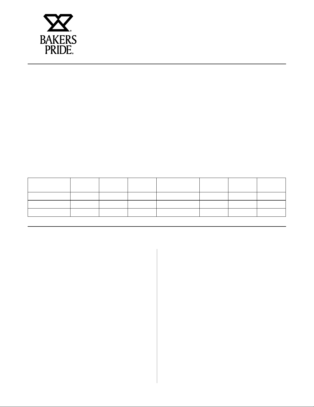
TABLE OF CONTENTS
FLOOR MODEL ELECTRIC DECK OVEN OPERATION MANUAL
INSTALLATION INSTRUCTIONS 1
RECEIVING 1
LOCATION AND MINIMUM CLEARANCES 1
INSTALLATION 1
STACKING 3
STEAM OPTION 3
INSTALLATION OF DECKS 4
ELECTRICAL CONNECTION 5
SYSTEM CHECK 6
INITIAL START-UP 6
OPERATING INSTRUCTIONS 7
GENERAL BAKING 7
GENERAL BAKING TIPS 7
SPECIAL FEATURES 8
CLEANING 8
SERVICE AND TROUBLESHOOTING 9
SERVICE AND TROUBLESHOOTING CHART 10
RATING PLATE 10
PARTS LIST W/EXPLODED VIEW 11
WIRING DIAGRAMS 13
WARRANTY 19
Models Covered
Model Elements
Per Deck
EP1(2,3)-8-3836 8 8 1 or 3 EB1(2,3)-8-5736 12 12 1 or 3
EP1(2,3)-8-5736 12 12 1 or 3 ER1(2,3)-12-3836 8 8 1 or 3
EB1(2,3)-8-3836 8 8 1 or 3 ER1(2,3)-12-5736 12 12 1 or 3
Total Kw
Per deck
Phase Model Elements
Per Deck
Total Kw
Per deck
Phase
INSTALLATION INSTRUCTIONS
Receiving
Read the notice on the outside carton regarding damage
in transit. “CONCEALED DAMAGE”, damage discovered
after opening the crate(s), must be reported immediately
to the carrier. The carrier will perform an inspection of
the damage and furnish forms for the consignee’s claim
against the carrier. Retain all packing material- including
outer carton until the inspection has been completed.
Location And Minimum Clearances
Adequate air space must be provided for proper venting
of the controls and provisions must be made for venting
of the cooking vapors. The Oven must be installed in a
well-ventilated area and following minimum clearances
must be maintained at all times:
Ovens can be installed with “Zero” clearances (back
and sides) from combustible and non-combustible
materials.
The Ovens may be installed on combustible Flooring if
mounted on the Legs provided. Keep the area around
your oven free and clear of all combustible materials.
Installation
Place the oven and parts as close to the area of final
installation before un-crating. Your oven is packed
sitting on its back. Leave it on its back while unpacking.
The pallet may be left under oven for convenience in
further handling. Unpack carefully to avoid damage to
the oven. If concealed damage is discovered, follow the
instructions detailed in Receiving section above.
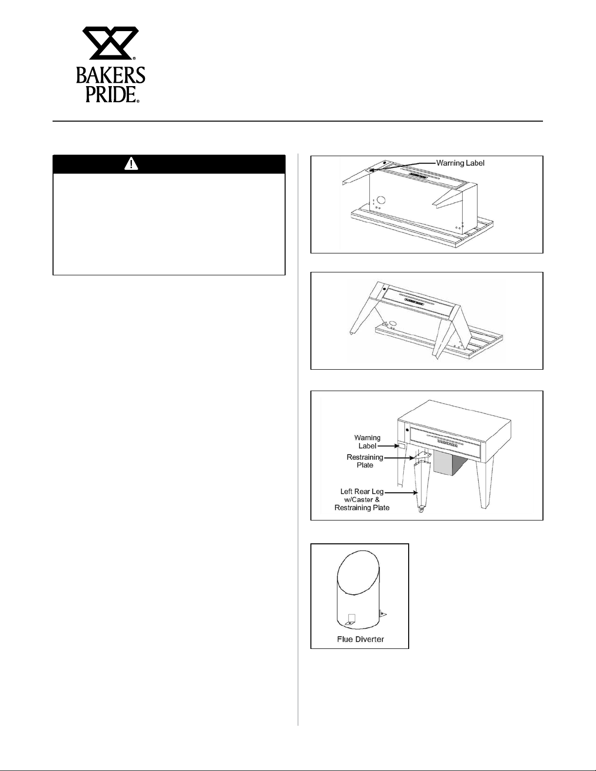
a) Legs are shipped in a separate carton complete
with mounting bolts and washers. Firmly bolt two
legs (in case of casters, the two with the brakes
must be used here) to the upper two corners
(front) of the oven as it rests on the pallet. Note:
(See Fig. 1).
b) Using sufficient help, tilt the oven forward and
lower it down so that the two front legs come to
rest on the floor. (See Fig.2)
1
Page 4
FLOOR MODEL ELECTRIC DECK OVEN OPERATION MANUAL
INSTALLATION INSTRUCTIONS
WARNING
In case of casters, the brakes must be firmly
applied and in a locked position before
proceeding with the next step, in order to prevent
the oven from rolling away while lifting the back.
It is advisable to have a person in front of each
caster leg, bracing his foot firmly against the
casters.
c) Using proper lifting equipment, raise the back of
the oven to a height slightly more than the height
of the legs, remove the pallet and the rest of the
packing material and place a sturdy support under
the back side. (See Fig. 3)
Figure 1
d) Mount the two back legs and firmly tighten the
bolts, then lift the back of the oven somewhat and
remove the support.
e) Provide a suitable restraining chain or cable to
securely tether the appliance to the building
structure. The restraining chain or cable should
be of such length that it will stop movement of
the appliance BEFORE there is any strain on the
power supply cable.
f) Move the oven to its final location (in case of
casters, release the brakes, then reapply once in
position), maintaining the minimum distances
specified in Minimum Clearances section above.
g) Remove all loose parts and packages from the
oven interior.
h) Insert the short piece of tapered pipe supplied (see
fig.4) into the hole at the top, located near the left
rear corner of the oven (see fig.5A). Turn it to the
desired direction, mark the location of the holes
and drill three 1/8” diameter holes, then secure it
with the screws supplied for that purpose. This pipe
is to prevent accidental closure of the vent opening
by items stored on top of the oven.
Figure 2
Figure 3
Figure 4
2
Page 5
FLOOR MODEL ELECTRIC DECK OVEN OPERATION MANUAL
INSTALLATION INSTRUCTIONS
Stacking
These ovens can be stacked up to three high. Each unit
is built exactly the same, so it does not matter in what
order they are stacked. However, in case of a mix of 8”
and 12” deck heights, it is advisable to place the higher
deck(s) on the top, e.g.: mount the legs to one of the
lower decks.
Once the unit with the legs is in place (in case of casters
make sure the brakes are on), with the proper lifting
equipment gently place the next oven on top of the first
one and line up the back and sides with each other. (If
the ovens came with Steam Option, read Steam Option
section below before proceeding). Once the two ovens
are properly stacked, install the stacking brackets as
per instructions supplied with the kit. In case of a third
unit, gently place the oven on top of the second one,
line up the back and sides, then connect to the stacking
brackets.
Steam Option
If this option has been ordered and supplied, remove
the control panel(s) and left access cover(s) to gain
access to the steam plumbing as follows:
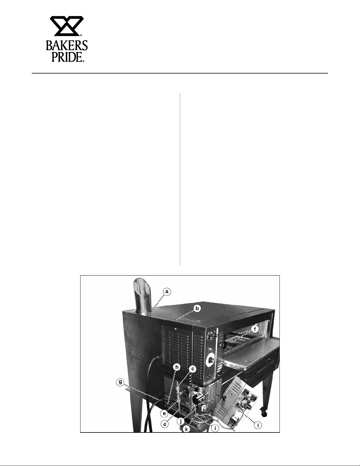
a) Remove all screws and vent knob from the control
panel. Loosen the set screw on the thermostat
knob and remove it. Pull the control panel out
at the bottom, then down and out from the vent
rod. Slip the right flange hole of the control panel
back onto the vent rod, then replace the vent knob
to keep the control panel in an open and secure
position. (See Fig. 5i)
b) Remove all screws from the left access panel, then
pull it forward and out of the oven.
c) After the internal pipe connections have been
completed as per instructions below, follow the
instructions supplied by the manufacturer of the
steam generator and the manufacturer of the
steam trap for final hook up to the steam supply.
Stacked Ovens
a) In all but the top oven, punch four 1 1/2”
diameter holes in each of the top covers, utilizing
the 1/8 locating holes. (See Fig. 5b)
b) Loosen the upper pipe union(s) and remove the
upperpart(s) from all but the top oven.
(See Fig. 5c).
Figure 5
3
Page 6
FLOOR MODEL ELECTRIC DECK OVEN OPERATION MANUAL
INSTALLATION INSTRUCTIONS
c) Raise the left side of the upper unit and place a
piece of wood or similar material to keep a 1” to
1 1/2” space between the two ovens.
d) Insert the connecting pipe, small end up,
(see Fig. 5d) through the access opening of the
lower unit and screw it into the lower pipe union of
the upper oven, leaving a space between the lower
union sections identical to the space between the
two ovens.
e) Lift the upper unit, remove the spacer and carefully
lower it until the two union parts in the lower oven
meet. Adjust the height of the connecting pipe,
if necessary, to have a perfect match at the lower
union, then tighten the lower union.
WARNING
It is very important to have a good match at the
lower union before tightening it. If the connecting
pipe is too long or too short, this will put undue
stress on the pipe joints and could cause failure
of these components and property damage or
injuries as well.
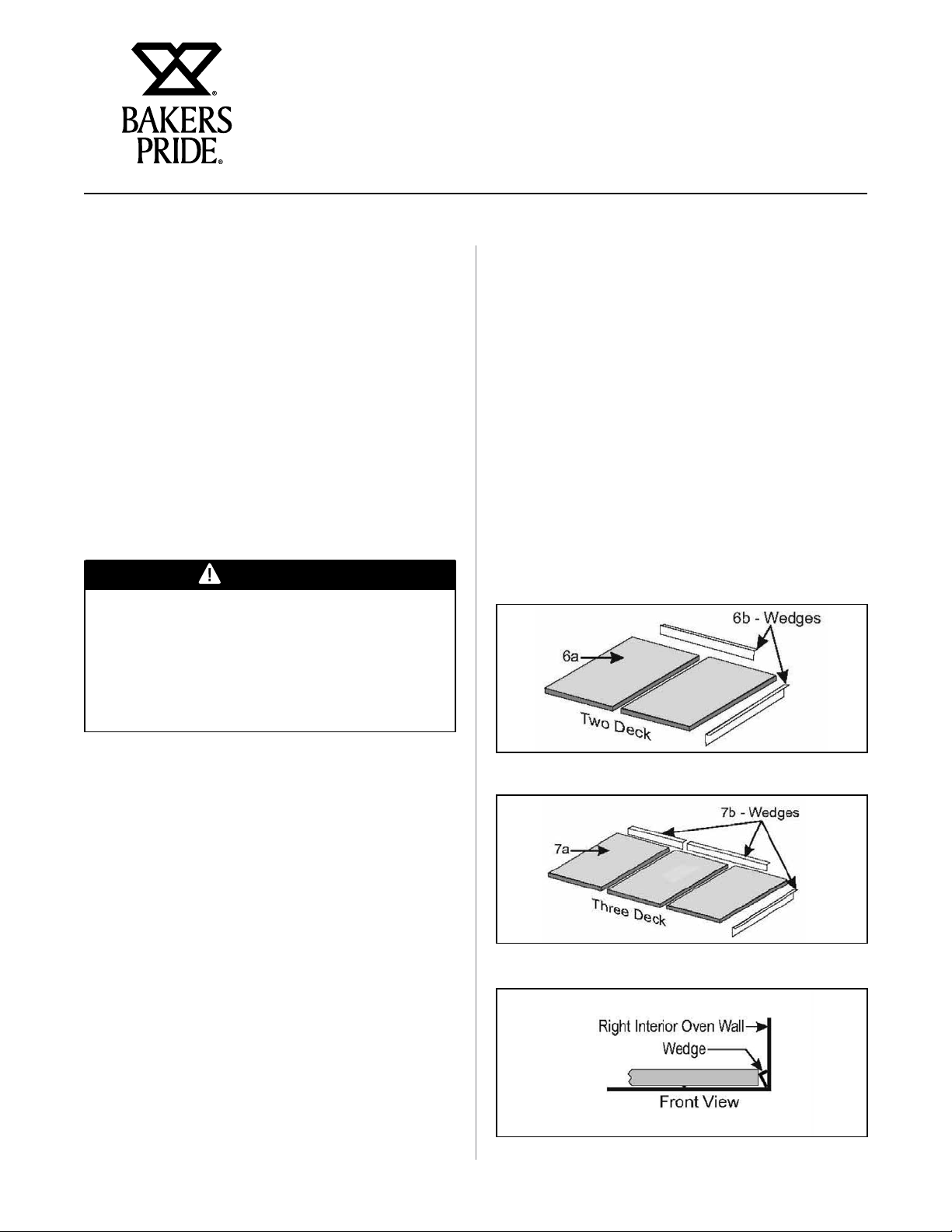
a) Depending on the model, three or four deck
supports (metal channels) have to be inserted in
the oven, front to back, flanges down and flat side
up. (See Fig.5f).
b) Slide one slab into the bake chamber along the
deck supports on the left side, lower the front end
carefully to avoid chipping of the deck corners,
then push tightly against the left oven wall.
c) Repeat the above for the second (and third)
slab, pushing it as tightly as possible against the
previous one to prevent any gaps.
d) With a long hook or similar tool, reach in and pull
all of the slabs as far to the front as possible. Insert
one (or two) of the wedges in the back and one at
the right side of the oven (see Figs. 6b & 7b) and
tap them down lightly.
f) At the end, insert the connecting pipe, small end
up, through the appropriate opening at the base of the
bottom unit and screw it into the lower pipe union.
Single Oven
Insert the connecting pipe, small end up, through the
appropriate opening of the base and screw it into the
lower pipe union. (See fig. 5e)
Installation Of Decks
Steel Decks
Steel Decks for Bake and Roast Application are factory
installed and no further installation is required.
Ceramic Decks
Ceramic Decks for Pizza Application are shipped in a
separate carton. Depending on the model, two
(see Fig. 6a) or three slabs (see Fig 7a) are provided
with each oven. This material is heavy and fragile and
should be handled carefully.
Figure 6
Figure 7
Figure 8
4
Page 7

FLOOR MODEL ELECTRIC DECK OVEN OPERATION MANUAL
INSALLATION INSTRUCTIONS
Electrical Connection
General Instructions
a) Only a licensed electrician should make the
electrical connections.
b) Make sure electrical supply corresponds with that
specified on the rating plate.
c) Only use copper conductors rated at 90°C
suitability sized for the electric current drawn.
d) All pole disconnect(s) must be provided by the
installer.
E(PBR) – 3836 – 8(12) Power and Current per Deck Power Supply
KW L1 (amp) L3 (amp) L2 (amp) N (amp) KW L1 (amp) L3 (amp) L2 (amp) N (amp)
8.0 38.6 38.6 208(1) 12.0 57.8 57.8
8.0 21.0 25.0 21.0 208 (3) 12.0 33.5 33.3 33.5
7.3 – 8.7 33.3-36.3 33.3-36.3 220-240 (1) 11.0-13.0 50.0-54.6 50.0-54.6
7.3 – 8.7 18.0-19.7 21.5-23.5 18.0-19.7 220-240 (3) 11.0-13.0 29.0-31.6 28.9-31.5 29.0-31.6
7.3 – 8.7 16.7-18.2 16.7-18.2 440-480 (1) 11.0-13.0 25.0-27.3 25.0-27.3
7.3 – 8.7 9.0-10.0 10.8-11.8 9.0-10.0 440-480 (3) 11.0-13.0 14.5-15.8 14.4-15.7 14.5-15.8
8.0 35.0 35.0 400-Y (1) 12.0 52.3 52.3
8.0 8.38 13.0 13.0 4.2 400-Y (3) 12.0 17.5 17.4 17.4 0.1
NOTE: EACH OVEN REQUIRES A SEPARATE CONNECTION !
Volts (Phase)
e) When installed, unit must be electrically grounded
in accordance with the local codes and/or the latest
edition of the National Electrical Code ANSI/NFPA
No. 70 in USA or Canadian Electrical Code, CSA
Standard C22.1, Part 1 in Canada.
f) FOR CE UNITS: The appliance must be connected
by an earthing cable to all other units in the
complete installation and thence to an independent
earth connection in compliance with EN 60335-1
and/or local codes. If flexible line cordage is used
to connect the equipment, it should be a minimum
of H07RN-F type conforming to EN60335-1 and/or
local codes.
E(PBR) – 5736 – 8(12) Power and Current per Deck
CAUTION
Overexposure to smoke or fumes may cause
nausea and dizziness. Be sure the oven is placed
in a well ventilated area.
Field Connections
a) Remove all screws and vent knob from the control
panel(s). Pull control panel out at the bottom,
then down and out from the vent rod. Slip the right
flange hole of the control panel back onto the vent
rod, then replace the vent knob to keep the control
panel in an open and secure position.
b) Remove all screws from the left access panel(s),
then pull forward and out of the oven.
Stacked ovens only!
In all but the top oven, punch four 1 1/2” diameter holes
in each of the top covers, utilizing the 1/8 locating holes.
(See Fig. 5b)
c) Feed power cable (supplied by the customer) through
the access hole at the left side (see Fig 5g) or at the
bottom (see fig. 5h) of the oven and pull the cable to
the front of the oven where it may be attached to the
opening in the oven frame. See fig. 5i).
d) Following the appropriate wiring diagram conforming
to the rating plate, connect the power supply leads
to the field wiring terminal block (see fig. 5j). The
ground wire should be connected to the grounding
lug (see fig. 5k) attached to the oven frame.
e) For single phase 2-wire or three phase 3-wire
supplies, the controlling branch circuit is designed
to operate at 208-240 volts AC and is pre-wired at
the factory between L1 and L2 of the field wiring
terminal block.
5
Page 8

FLOOR MODEL ELECTRIC DECK OVEN OPERATION MANUAL
INSTALLATION INSTRUCTIONS
f) For three phase 4-wire 230/400 Volts AC 50hz
supplies, the controlling branch circuit is designed
to operate at 230 volts AC and is pre-wired at
the factory between L1 and N of the field wiring
terminal block.
g) Make sure all connections are tight, then replace
the access cover(s) and control panel(s).
System Check
a) Flip up oven light switch. Oven lights will go on,
and off as the switch is pushed down again.
b) Set the Top (right) and Bottom (left) Heat switches
to “0” (off).
c) Turn the Thermostat knob to 300°F (150°C).
Nothing should happen.
d) Turn the Top (right) heat switch counter-clockwise
to “5”. The top amber indicator lamp will
illuminate; the right contactor will be activated and
the top heating elements will be energized. After
some time, these items will start to cycle on and
off.
e) Turn the Top (right) heat switch clock wise to
“10” (high). The top amber indicator lamp will
illuminate; the right contactor will be activated and
the top heating elements will be energized and all
should stay that way until the heat switch is turned
back to “0” again or the preset temperature has
been reached.
f) Repeat d) and e) above with the Bottom (left) Heat
switch. The results should be the same as above,
except this time it will be the bottom indicator
lamp, the left contactor and the bottom heating
elements.
Ovens with Steam Option
Never activate the steam timer when the oven is cold,
since the steam will immediately condense and turn to
water.
a) The steam timer can be adjusted from 1 to 60
seconds and has been factory set for 3-5 seconds.
To change this time, insert a small screw driver
through the 1/4” diameter hole below the steam
switches and turn the timer shaft clockwise to
increase or counter-clockwise to decrease this time
delay setting.
b) Press both steam switches simultaneously. The red
indicator lamp will illuminate; the solenoid coil will
be activated and the solenoid valve will open and
allow steam to enter the baking chamber for the
duration of the selected time. After that period, the
power to the red indicator lamp and solenoid coil
will be cut off and the solenoid valve will shut down
the flow of steam to the oven.
WARNING
Never open the door while the red indicator lamp
is on and steam is being injected into the oven,
since exposure to Iive steam can cause serious
injuries.
Initial Start-Up
After installation, your oven will need a few hours to
evaporate the moisture in the deck and in the insulation
and to burn off the thin coat of oil on the sheet metal
parts. The following steps must be completed before
your new oven is ready for use:
Ovens with Timer Option
Turn the timer knob clockwise past the “0” and set a
time of 2 minutes. At the end of 2 minutes, the timer
knob will be at “0”, you will hear the buzzer and see the
green indicator lamp on, and all three will stay that way
until you turn the timer knob counter-clockwise to “0”
to switch them off, or turn the knob clockwise for more
time and repeat the above with the same or a different
setting.
a) Place the oven in a well-ventilated area in order to
deal with the ensuing smoke and smell.
b) Open the oven door and make sure the oven cavity
is empty and that the decks are properly installed
(see Installation of Decks section).
c) Close the oven door and set the temperature knob
to 300°F (150°C) for about an hour or so.
6
Page 9

FLOOR MODEL ELECTRIC DECK OVEN OPERATION MANUAL
INSTALLATION INSTRUCTIONS
d) After that, increase the temperature to 500°F
(260°C) for at least another hour or until all the
smoke and fumes have disappeared. This procedure
will remove most of the moisture and help insure
good bake results.
OPERATING INSTRUCTIONS
General Baking
NOTICE
Only Pizza and Bread products can have direct
contact with the Ceramic Deck. All other food
products must be placed in a metal pan or
porcelain dish to avoid direct contact with the
ceramic deck.
Pizza can be baked on the deck, on a screen or in a
pan. When you determine the combination of method,
ingredients and temperature that results in the right
bake for your crust, sauce and cheese combination and
your customer’s taste, mark and keep it.
Deck baking refers to baking Pizza directly on the deck.
Generally, it is a thin product that requires temperature
of at least 550°F (290°C).
Screen baking refers to baking Pizza on a screen. The
screen lifts the Pizza off the deck. The screen may
be removed near the end of the bake time to give the
bottom of the Pizza a crispier crust and a darker color.
Bake temperatures range from 500°F (260°C) to 550°F
(290°C).
Pan baking refers to baking Pizza in pans. Crusts can
be thick or thin and toppings range from light to heavy.
Bake temperatures for pan baking range from 450°F
(235°C) to 500°F (260°C).
CAUTION
Overexposure to smoke or fumes may cause
nausea and dizziness. Be sure the oven is placed
in a well ventilated area.
General Baking Tips
a) At day’s end, turn the thermostat to the “0” (off)
position to conserve energy, leaving the Top and
Bottom Heat controls set for next day’s operation.
b) In the morning, preheat for one hour at 50°F (30°C)
lower than your baking temperature with the vent
closed (pushed all the way in) for a faster recovery.
c) 15 to 20 minutes before loading the oven, raise the
thermostat setting to your baking temperature and
make sure the Top and Bottom Heat switches are
set correctly for the product you intend to bake.
d) Check the bottom color of the Pie and reduce the
Top Heat once you notice the bottoms to get very
light. This will make the bottom elements come on
more often helping to maintain the desired color.
e) When the oven has not been used for a while, there
is a tendency for the bake deck to get very hot.
Consequently, when it is slow and the oven idling,
set the thermostat at least 50°F (30°C) lower than
your normal baking temperature. Then, when
you put in a pizza, increase the normal setting,
providing the quick extra top heat required to
balance the bottom heat. At the end of the bake,
the thermostat should then be turned down to lower
setting before the deck gets too hot again.
f) Frequently scrape and brush off decks top remove
burnt residue which can cause an “off” flavor and
increase bake time.
7
Page 10

FLOOR MODEL ELECTRIC DECK OVEN OPERATION MANUAL
OPERATING INSTRUCTIONS
g) Heavily topped Pizza or Pan Pizza require lower
bake temperatures and longer bake times as
compared to a regular thin Pizza with light
toppings.
h) Bubbles in fresh dough indicate an under-proofed
or cold product. Allow the dough balls to proof in a
warm area and to double in size before baking.
i) Any type of Pan or Screen may be used in this
oven. When choosing pans, be sure to pick a pan
which is closest in height of your product.
NOTICE
Dark colored pans and screens transfer heat better
than light colored aluminum pans or screens. The
latter ones must be seasoned before use. To do
this, apply a heavy coating of cooking oil inside
and out and bake in oven at 500°F (260°C} for
about an hour or until all smoke has gone.
Special Features
Heating Elements:
For a more even heat distribution, these ovens have
evenly spaced u-shaped heating elements throughout
that are either “ALL ON” or “ALL OFF”, depending on
the temperature setting and the Top and Bottom Heat
selections made.
Infinite Switches:
To better control the ratio of Top and Bottom Heat, these
ovens have two heat selector switches, one controlling
the Top Heat the other controlling the Bottom Heat.
Each allows a setting from #1 (low= 20% on/80% off)
through #9 (80% on/20% off) to #10 (high = 100%
on). In order to maximize the potential of the oven and
to get maximum power, both heat selector switches
should be set to #10 (high). This will be the best setting
most of the time for most of the products. However,
if, after some experimenting, one of the two proves to
be too hot, only that one should be reduced while the
other one stays on high. There is no need to reduce
both at the same time. If less heat is required, lower the
thermostat setting.
Optional Timer:
Upon request, an electric timer is provided to give an
audible, continuous signal at the end of a preset time up
to 60 minutes (72 minutes with 50Hz supply) on Bake
Ovens and up to 5 hours (6 hours with 50Hz supply) on
Roast Ovens.
NOTE: The Timer does not control the heating elements.
Oven Lights:
The lights that illuminate your oven cavity should not be
left on when the door is closed. Leaving the lights on in
a hot oven for an extended time may cause them to fail.
Cleaning
Oven Exterior:
Clean Only When The Oven Is Cold.
a) Deposits of baked-on splatter and grease, or
discoloration may be removed with the stainless
steel cleaner sample supplied or by using any
commercial cleaner recommended for stainless
steel. Bakers Pride offers a stainless-steel cleaner
made expressly for this purpose. Always rub with
the grains and apply very light pressure. Rinse well.
b) A thin coat of light oil will add to the appearance of
the oven.
Oven Interior: (including Steel Deck}
Clean Only When The Oven Is Cold.
Use only the detergent solutions and cleaners that meet
the national and/or local codes. Clean the steel deck,
the ceiling and the walls of the baking chamber with a
mild soap and water solution.
Do not use oven cleaners, caustic solutions or
mechanical means as they will damage the interior
aluminized surfaces.
Ceramic Bake Decks:
Heavy And Fragile! Handle Carefully!
a) The bake decks should be cleaned by using a long-
handled scraper and stiff wire brush. At the end of
each day, turn the thermostat up to its maximum
setting and let the oven sit at that temperature for
at least 1/2 hour. This will burn off the food spilled
onto the baking decks during the day’s production
and turn it into ash. This ash can be brushed off
the next day before turning the oven on.
8
Page 11

FLOOR MODEL ELECTRIC DECK OVEN OPERATION MANUAL
OPERATING INSTRUCTIONS
b) The ceramic bake decks should be scraped and
brushed during the day also to help keep them
clean. To remove excessive crumbs or carbon, the
baking decks and the oven cavity may be vacuumed
when the oven is cold.
DO NOT USE WATER OR OTHER LIQUIDS ON THE
BAKING DECKS AS THAT MAY CAUSE THEM TO
CRACK.
After long use, heavily soiled bake decks may be cleaned
by turning over after scraping down and brushing off.
This will burn off the heavily soiled underside of the bake
decks over time. This procedure may be repeated as
needed.
Service And Troubleshooting
The ovens are designed to be as trouble free as
possible. Keeping the oven clean is about all that
is normally required. However, if your oven stops
operating, check the following:
a) The thermostat, to see if the set temperature has
been reached and the thermostat has turned off the
power to the heat control switches, indicator lamps,
contactors and heating elements.
Every six months (more frequently if the oven is
used heavily) the door spring mechanism and
all moving parts must be inspected for wear. If
necessary, apply some lubricants to the door
pins and bearing blocks at each side of the oven
door. Use only lubricants that meet the national
and/or local codes.
DO NOT APPLY GREASE OR OIL TO SPRING
LEVER SHOULDER BOLT AND SPRING
ROLLER, THEY HAVE SELF-LUBRICATING
INSERTS THAT WILL BE DAMAGED IF
LUBRICATED.
b) The infinite top and bottom heat control switches,
to see if they are “on”. They must be in a set
position (other than off) for indicator lamps,
contactors and heating elements to operate.
c) The power supply fuses/ breakers, to see if they are
blown / or have tripped.
d) The two branch protection fuses in the control panel
of the oven, to see if one or both of them are blown.
If the oven still does not operate, disconnect the power
supply to the unit by turning off the main switch,
then contact the factory, factory representative or an
authorized service agency.
All servicing should be performed by a factory
authorized technician only.
9
Page 12

FLOOR MODEL ELECTRIC DECK OVEN OPERATION MANUAL
OPERATING INSTRUCTIONS
Troubleshooting Chart
Problem Probable Cause Remedy
Indicator light is out Set temperature has been reached. Take no action. The thermostat has turned off the power to the heat
switches, indicator and heating elements. When oven starts to cool, all
functions will be restored.
The infinite top and bottom heat control switches
are “OFF”.
One or both branch protection fuses in the Replace fuse(s).
No power Power supply fuses or circuit breakers are blown or
have been tripped.
Oven too Hot Thermostat set too high. Lower the thermostat setting. Allow several hours for heat to regulate.
Thermostat may bedeffective. Call local authorized Bakers Pride service agent.
Bottom of pies are
undercooked
Bottom of pies burn
before toppings are
cooked
Pies cook unevenly
If the same area of the deck is used repeatedly, the
deck temperature in that area will be reduced.
Bottom infinite switch set too low. Increase setting.
Top infinite switch set too high. Decrease setting.
Deck temperature too hot - especially during slow
periods
Bottom infinite switch set too high. Decrease setting.
Top infinite switch set too low. Increase setting.
Exhaust fan may be too powerful. Reduce fan speed.
Areas adjacent to oven walls are generally hotter. Rotate pies (180°), once during each bake or keep to the center of oven.
Sometimes the left rear is not cooking as fast as the
rest of the oven because the moisture vent is open.
Turn switches to a position other than “OFF”. This will allow indicator
lamps, contactors and heating elements to operate.
Replace fuse or reset circuit breaker.
Rotate pies to unused areas of the bake deck that are hotter and will cook
the bottoms faster.
Reduce Thermostat setting by 50°-75° below normal bake temperature.
When decks cool begin cooking and immediately increase the thermostat
setting by 50° - 75°.
Close the moisture vent.
Rating Plate
A copy of the rating plate is enclosed. Please keep for future reference.
For further information and to purchase the deck scraper/brush, or stainless steel
cleaner, call Bakers Pride toll-free at: (800) 431-2745.
Model Number:
Serial Number:
Voltage:
Phase:
Date Code:
Date Purchased:
Purchased From:
Please fill in the above rating plate information and keep for future reference.
This information will be necessary in the future when ordering parts or requesting
warranty service.
10
Page 13

FLOOR MODEL ELECTRIC DECK OVEN OPERATION MANUAL
OPERATING INSTRUCTIONS
Parts List and Exploded View
Exploded View: EP, EB & ER Electric 3836/5736 Deck Oven
11
Page 14

FLOOR MODEL ELECTRIC DECK OVEN OPERATION MANUAL
OERATING INSTRUCTIONS
Item 3836 5736 Description
1 C4038K C4039K Deck Trim
2 C4049U C4050U Outer Back Asm 8”
3 C4142U C4143U Outer Back Asm 12”
4 C4056U C4057U Outer Top Asm
5 C4067K C4068K Top Trim
6 C4077K C4078K Bottom Apron
7 C4079K C4080K Top Apron
8 T1224U T1225U Steel Deck Asm
9 T1232Y T1232X Hearth Baking Deck
(Set/2-3836 / Set/3-5736)
10 T1232A T1232A Hearth Baking Deck 19 x 36 x 1 (each)
11 S6060Y S6060X Insulation Needled Blanket 1”
Item 8” 12” Description
12 C4047K C4140K Outer Side LH
13 C4048K C4141K Outer Side RH
14 C4053K C4144K Access Cover LH
15 C4054K C4145K Access Cover RH
16 S3242U S3244U Door Arm Asm LH
17 S3243U S3245U Door Arm Asm RH
18 C4076K C4146K Front Column RH
Item All Models Description
19 C4040K Deck Support
20 C4059K Side Top Trim LH (All)
21 C4060K Side Top Trim RH (All)
22 C4069K Thermostat Bracket
23 C4070U Fuse Block Bracket Asm
24 C4071K Lamp Mount
25 C4074K Spring Guard
26 C4075U Spring Bracket Asm
27 C4109K Deck Spacer Side 36”
28 C411OK Deck Spacer Back 19”(3836-2 needed, 5736-3 needed)
29 C4098X Capillary Clip Kit
30 C41OOK Control Panel - Pizza 8” 680F
31 U1352A Overlay (for C41OOK)
32 C4089K Control Panel -Bake 8” 550°F 60 Minute
33 U1353A Overlay (for C4089K)
34 C4091K Control Panel -Roast 12” 550°F 60 Minute
35 U1355A Overlay (for C4091K)
36 C4093K Control Panel -Roast 12” 550°F 5 Hour
37 U1354A Overlay (for C4093K)
38 C4095K Steel Deck Clip (3836-2 needed, 5736-3 needed)
39 C4103K Steam Control Bracket
40 C4105K Stacking Bracket E-PB-2 (set/2) w/Screws
41 C4106K Stacking Bracket E-R-2 (set/2) w/Screws
42 C4107K Stacking Bracket E-PB-3 (set/2) w/Screws
43 C4108K Stacking Bracket E-R-3 (set/2) w/Screws
44 C4113U Transformer Bracket Asm
45 C4161K Solenoid Bracket
46 L1178A Heater Element 1000W 230V (each) w/Cap
47 L1179A Heater Element 1000W 208V (each) w/Cap
48 L1180A Heater Element 1000W 460V (each) w/Cap
49 M1192A Thermostat 3 Pole 800F 300V 16A
50 M1369A Thermostat 3 Pole 550F 300V 16A
51 M1176A Potentiometer (Steam)
52 M1231A Timer SS (Steam)
Item All Models Description
53 M1259A Toggle Switch DPST on-off 250/125V 10/15 A (Light)
54 M1382A Electric Timer, 250V, 60 Minute
55 M1367A Infinite Switch 208V 25A (Top & Bottom Heat Control
56 M1368A Infinite Switch 240V 25A (Top & Bottom Heat Control
57 M1370A Hi-Limit Switch 140C 240/120V 10/15A
58 M1371A Contactor 4 Pole 600V 25A 208V 50/60Hz
59 M1372A Contactor 4 Pole 600V 25A 220-240V 50/60 Hz
60 M1387A Solenoid Valve 1/2B 1/2P
61 M1374A Electric Timer 250V 5 Hour
62 M1388A Solenoid Coil 208-240V 50/60Hz
63 M1376A Transformer 480/240V 0.25KVA
64 S1022X Caster 4” No Lock (each)
65 S1023X Caster 4” w/Lock (each)
66 P1004A Terminal Block 4 Pole 600V 85A
67 P1025A Grounding Lug 140A
68 P1098A PB Switch SPST Mom Contact 2501125V3/6A(Steam)
69 P1118A Fuse KTK Class CC 600V 1OA
70 P1128A Indicator Lamp 1/2” 250V 113W Green (Timer)
71 P1145A Lamp Asm 240V 15W
72 P1150A Mounting Strip for Contactors
73 P1164A Fuse KTK Class CC 600V 30A
74 P1165A Fuse Block 2 Pole 600V 30A
75 P1166A Fuse Block 3 Pole 600V 30A
76 P1167A Indicator Lamp 1/2” 250V 1/3 W/Amber (Heat selector)
77 P1168A Indicator Lamp 1/2” 250V 113W Red (Steam)
78 Q3001A Flat Washer 19/32 x 1” x 1/8 (2)
79 Q3002A Flat Washer 19/32 x 1” x 1/16 (4)
80 Q3007A Split Lock Washer 9/16 (Door Rod)
81 Q2401A Hexagon Nut 9/16-18 (Door Rod)
82 Q301OA Flat Washer 7/16 x 1” x 5/64 (Bushing/Sleeve)
83 Q2301A Shoulder Bolt 3/8-16 x 1” (Bushing/Sleeve)
84 S1005A Push-Pull Knob 3/8-16 (Vent)
85 S1018Y Legs 12” (Set/4 w/Bolts & Washers)
86 S1018T Leg 12” (each) w/Bolts & Washers
87 S1004Y Legs 30” (Set/4) w/Bolts & Washers)
88 S1004X Leg 30” (each) w/Bolts & Washers
89 S1406Y Legs 36” (Set/l4) w/Bolts & Washers)
90 S1406A Leg 36” (each) w/Bolts & Washers
91 S1019Y Legs 6” (Set/4) w/Bolts & Washers)
92 S1019T Leg 6” (each) w/Bolts & Washers
93 S1251Y Legs 24” (Set/4) w/Bolts & Washers)
94 S1251A Leg 24” (each) w/Bolts & Washers
95 S1196A Door Handle 30” w/Screws
96 S1205A Knob 1/4 D (Heat Selector)
97 S1311A Knob 1/4 D (Timer/Thermostat)
98 S3004A Door Spring 13/16 x 6-3/4
99 S3003A Door Spring 1-1/8 x 9-3/4
100 S3108A Bushing/Sleeve Asm
101 S3239A Bearing Block 1 x 1 x 1/2 Bronze
102 S3241A Flue Rod 3/8-16 x 37”
103 U1043A Bakers Pride Logo 13-1/4
104 C4085T Door Asm 3836-8” w/o Door Arm Asm’s
105 C4086T Door Asm 5736-8” w/o Door Arm Asm’s
106 C4151T Door Asm 3836-12” w/o Door Arm Asm’s
107 C4152T Door Asm 5736-12” w/o Door Arm Asm’s
108 A3295E Spring Lever
109 S1075X S/S Leg Wrap 6” (Set/2)
110 S1076X S/S Leg Wrap 12” (Set/2)
111 S1331X S/S Leg Wrap 24 1/2” (Set/2)
112 S1078X S/S Leg Wrap 30” (Set/2)
113 S/S Leg Wrap 30” (Set/2)
Note: When ordering parts, ALWAYS specify Part Number, Model Number, Serial Number, and Voltage/Phase.
12
Page 15

FLOOR MODEL ELECTRIC DECK OVEN OPERATION MANUAL
OPERATING INSTRUCTIONS
Wiring Diagrams
Wiring Diagram: EP(B,R) -8(12) -5736 208, 240 or 440-480V, 1PH, 2W or 3PH, 3W
13
Page 16

FLOOR MODEL ELECTRIC DECK OVEN OPERATION MANUAL
OPERATING INSTRUCTIONS
Wiring Diagram EP(B,R) -8(12) -3836 208, 240 or 440-480V, 1PH, 2W or 3PH, 3W
14
Page 17

FLOOR MODEL ELECTRIC DECK OVEN OPERATION MANUAL
OPERATING INSTRUCTIONS
Wiring Diagram: EP(B,R) -8(12) -5736 230/400V – STAR
15
Page 18

FLOOR MODEL ELECTRIC DECK OVEN OPERATION MANUAL
OPERATING INSTRUCTIONS
Wiring Diagram EP(B,R) -8(12) -3836 230/400V – STAR
16
Page 19

BAKERS PRIDE LIMITED WARRANTY
WHAT IS COVERED This warranty covers defects in material and workmanship under normal use, and applies only to the original purchaser
• The equipment has not been accidentally or intentionally damaged, altered or misused;
• The equipment is properly installed, adjusted, operated and maintained in accordance with National
• The serial number rating plate affixed to the equipment has not been defaced or removed.
WHO IS COVERED This warranty is extended to the original purchaser and applies only to equipment purchased for use in the U.S.A.
COVERAGE PERIOD Cyclone Convection Ovens: BCO Models: One (1) Year limited parts and labor; (1) Year limited door warranty.
GDCO Models: Two (2) Year limited parts and labor; (2) Year limited door warranty.
CO11 Models: Two (2) Year limited parts and labor; (5) Year limited door warranty.
All Other Products: One (1) Year limited parts and labor. Warranty period begins the date of dealer invoice to customer
WARRANTY This warranty covers on-site labor, parts and reasonable travel time and travel expenses of the authorized service
COVERAGE Representative up to (100) miles, round trip, and (2) hours travel time. The purchaser, however, shall be responsible for
EXCEPTIONS All removable parts in Bakers Pride
providing that:
and local codes and in accordance with the installation instruction provided with the product;
or ninety (90) days after shipment date from Bakers Pride - whichever comes first.
all expenses related to travel, including time, mileage and shipping expenses on smaller counter models that may be
carried into a Factory Authorized Service Center, including the following models: PX-14, PX-16, P18, P22S, P24S, PD-4,
PDC, WS Series and BK-18.
®
and Valves, are covered for a period of SIX MONTHS. All Ceramic Baking Decks are covered for a period of THREE
MONTHS. The installation of these replacement decks is the responsibility of the purchaser. The extended Cyclone door
warranty years 3 through 5 is a parts only warranty and does not include labor, travel, mileage or any other charges.
cooking equipment, including but not limited to: Burners, Grates, Radiants, Stones
EXCLUSIONS
INSTALLATION Leveling and installation of decks as well as proper installation and check out of all new equipment —per appropriate
REPLACEMENT PARTS Bakers Pride genuine Factory OEM parts receive a (90) day materials warranty effective from the date of installation by a
This Warranty is in lieu of all other warranties, expressed or implied, and all other obligations or liabilities on the manufacturer’s part. Bakers Pride
shall in no event be liable for any special, indirect or consequential damages, or in any event for damages in excess of the purchase price of the unit.
The repair or replacement of proven defective parts shall constitute a fulfillment of all obligations under the terms of this warranty.
• Negligence or acts of God,
• Failures caused by erratic voltages or gas supplies,
• Thermostat calibrations after (30) days from
equipment installation date,
• Unauthorized repair by anyone other than a Bakers
Pride Factory Authorized Service Center,
• Air and Gas adjustments,
• Damage in shipment,
• Light bulbs,
• Alteration, misuse or improper installation,
• Glass doors and door adjustments,
installation and use materials — is the responsibility of the dealer or installer, not the manufacturer.
Bakers Pride Factory Authorized Service Center.
• Thermostats and safety valves with broken capillary
tubes,
• Fuses,
• Char-broiler work decks and cutting boards,
• Tightening of conveyor chains,
• Adjustments to burner flames and cleaning of pilot
burners,
• Tightening of screws or fasteners,
• Accessories — spatulas, forks, steak turners, grate
lifters, oven brushes, scrapers, peels. etc.,
• Freight — other than normal UPS charges,
• Ordinary wear and tear.
17
Page 20

IMPORTANT FOR FUTURE REFERENCE
Please complete this information and retain this manual for the life of the equipment. For Warranty Service and/or
Parts, this information is required.
Model Number Serial Number Date Purchased
NOTES
18
Page 21

NOTES
19
Page 22

Food Service Equipment Group
The Standex Food Service Equipment Group (FSEG) is a manufacturer of innovative commercial food
service equipment offering a wealth of refrigeration and cooking expertise. Products include walk-in
coolers and freezers; hot and cold display cabinets, cases, and storage systems; commercial ovens,
rotisseries, and cooking equipment; and rotary vane pumps.
Ask your sales representative about how the power of all Standex brands can work for you.
www.standex.com/segments/food-service
Be sure to keep up with new product announcements
and events on social media!
 Loading...