

Page 1
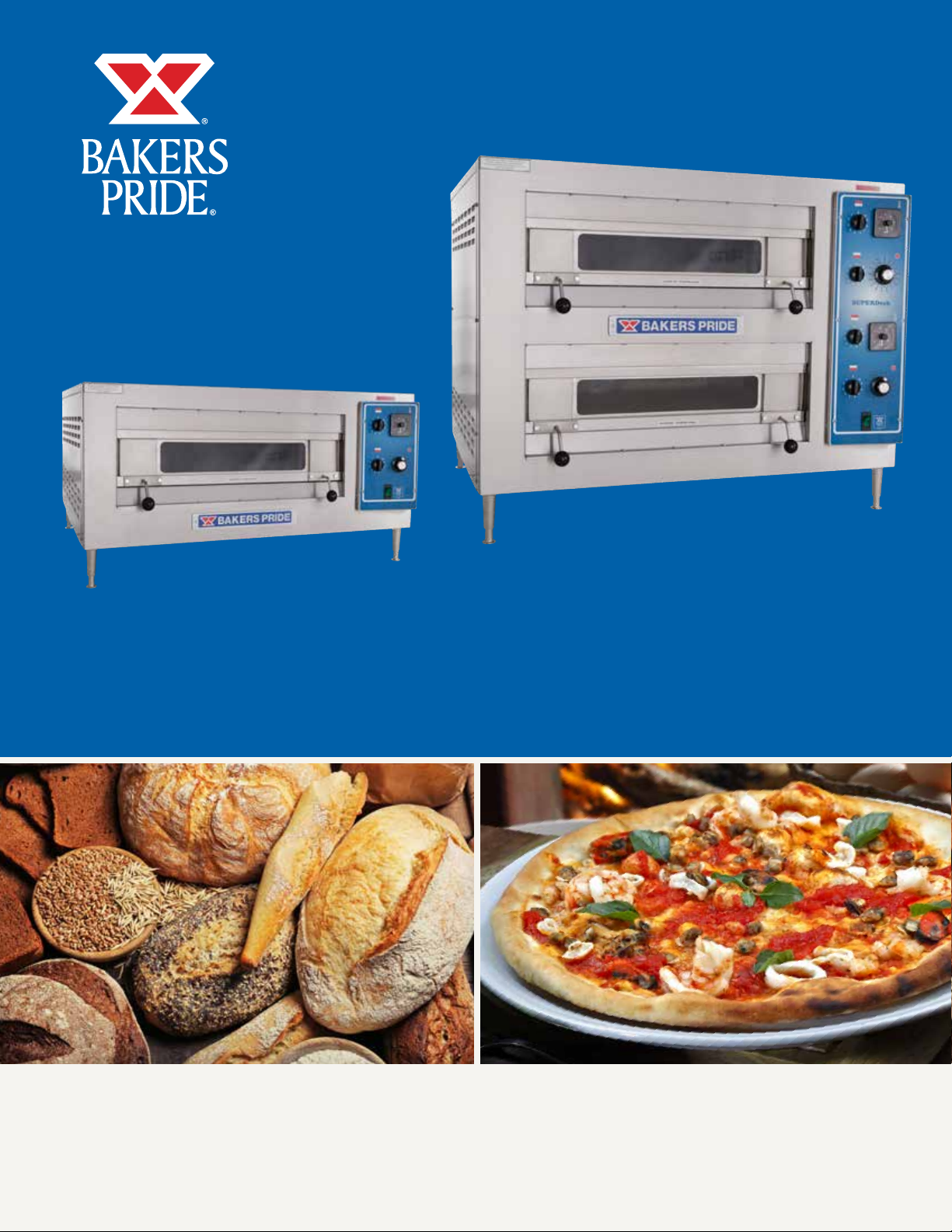
OPERATION MANUAL
HEARTHBAKE SERIES COUNTERTOP ELECTRIC DECK OVENS
SERIES: EP & EB
BUILT BY CRAFTSMEN. TESTED BY TIME®.
Page 2
COUNTERTOP ELECTRIC PIZZA OVEN OPERATION MANUAL
Models:
EP-1-2828, EB-1-2828
EP-2-2828, EB-2-2828
Bakers Pride Oven Company, LLC is a wholly owned
subsidiary of Standex International Corporation.
All gas operated Bakers Pride® countertop deck ovens
are intended for use with the type of gas specified on
the rating plate and for installation will be in accordance
with National Fuel Gas Code ANSI Z223.1 (latest
edition).
WARNING
FOR YOUR SAFETY: Do not store or use gasoline
or other flammable vapors or liquids in the vicinity
of this or any other appliance.
WARNING
CAUTION
Improper installation, adjustment, alteration,
service or maintenance can cause property
damage, injury or death. Read the installation,
operating and maintenance instructions
thoroughly before installing or servicing this
equipment.
NOTICE
Instructions to be followed in the event the user
smells gas must be posted in a prominent location
in the kitchen area. This information shall be
obtained from the local gas supplier.
WARNING
Initial heating of oven may generate smoke or
fumes and must be done in a well-ventilated
area. Overexposure to smoke may cause nausea
or dizziness.
California Residents Only
WARNING: This product can expose you to
chemicals including chromium which is known to
the State of California to cause cancer and birth
defects or other reproductive harm. For more
information go to www.P65Warnings.ca.gov.
BAKERS PRIDE OVEN COMPANY, LLC.
1307 N. Watters Rd., Suite 180
Allen, TX 75013
Phone: 800.527.2100 | Fax: 914.576.0605 | www.bakerspride.com
Please retain this manual for future references.
This equipment is design engineered for commercial
use only.
P/N U4186A 9/18
Page 3
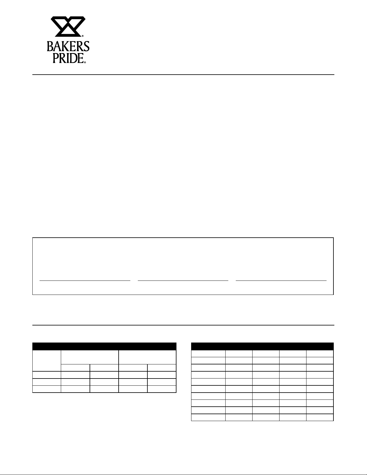
TABLE OF CONTENTS
COUNTERTOP ELECTRIC PIZZA OVEN OPERATION MANUAL
DIMENSIONS & SPECIFICATIONS 1
INSTALLATION 3
COUNTERTOP INSTALLATION 3
FLOOR INSTALLATION 4
OPTIONAL BASE FEATURE 4
DOUBLE STACKED OVENS 5
ELECTRICAL CONNECTIONS 5
EXPLANATION OF CONTROLS 6
USAGE RECOMMENDATIONS 7
TROUBLESHOOTING 7
Periodic inspections by your dealer or a qualified service agent is recommended. When corresponding with the factory
or your service agreement regarding service problems or replacement parts, be sure to refer to the oven by the correct
model number (including the prefix and suffix letters and numbers) and the warranty serial number. The rating plate
affixed to the oven contains this information.
CLEANING 8
EXTERIOR CLEANING 8
INTERIOR CLEANING 8
MAINTENANCE 8
REPLACEMENT PARTS 8
WIRING DIAGRAMS 8
PARTS LIST & EXPLODED VIEW 9
WIRING DIAGRAMS 11
WARRANTY 16
IMPORTANT FOR FUTURE REFERENCE
Please complete this information and retain this manual for the life of the equipment. For Warranty Service and/or
Parts, this information is required.
Model Number Serial Number Date Purchased
DIMENSIONS & SPECIFICATIONS
Minimum Clearances
Non-Combustible
Construction*
Inches mm Inches mm
Left Side 1 25 1 25
Right Side 1 25 1 25
Rear 1 25 1 25
Combustible
Construction*
Power Supply EP-1-2828 EP-2-2828
Volts KW Amperes KW Amperes
208-1 4.5 22 9.0 44
208-3 4.5 12.5 9.0 25
220-230-1 4.1-4.5 19 - 20 8.2-9.0 38 - 40
220-230-3 4.1-4.5 11 – 12 8.2-9.0 22 - 23
240-1 4.5 19 9.0 38
240-3 4.5 11 9.0 22
400-3Y 4.5 7 9.0 13
440-480-1 4.1-4.9 10 – 11 8.2 – 9.8 19 - 21
440-480-3 4.1-4.9 5.5 – 6 8.2 – 9.8 11 – 12
1
Page 4
COUNTERTOP ELECTRIC PIZZA OVEN OPERATION MANUAL
NOTICE
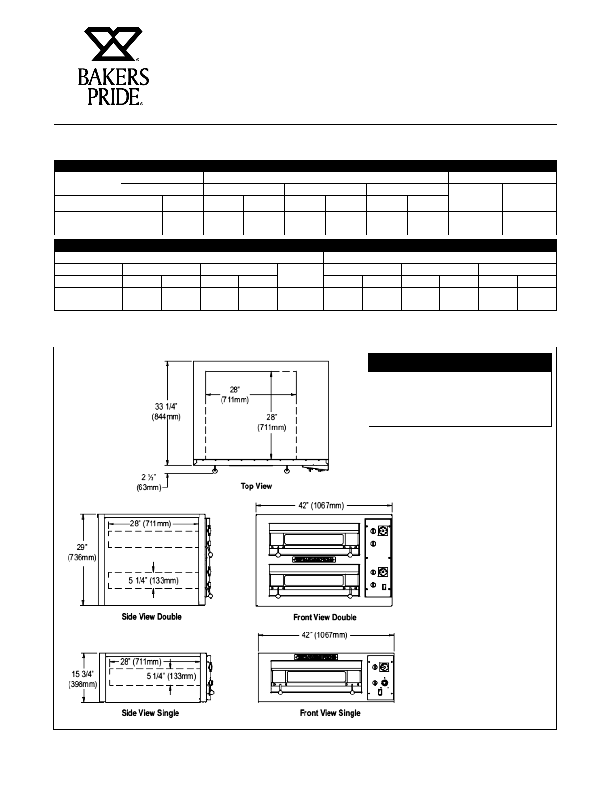
DIMENSIONS & SPECIFICATIONS
Shipping Information
Carton Dimensions Crate Size
Shipping weight Width Depth Height Cubic Feet Cubic Meters
Model Lbs. Kilos Inches mm Inches mm Inches mm
E-1-2828 310 141 43.5 1105 46 1168 37.5 952 43.5 1.23
E-2-2828 600 273 43.5 11058 46 1168 37.5 952 43.5 1.23
Specifications
Deck Size Overall Dimensions
L X W Height Number of
Model Inches mm Inches mm Inches mm Inches mm Inches mm
EP-1-2828 28x28 711x711 5.25 133 1 42 1067 33.25 845 15.75 400
EP-2-2828 28x28 711x711 5.25 133 2 42 1067 33.25 845 29 737
Decks
Width Depth Height
Each oven requires its own supply
connection to mains. Ovens are
shipped individually.
Dimensions
2
Page 5

COUNTERTOP ELECTRIC PIZZA OVEN OPERATION MANUAL
INSTALLATION INSTRUCTIONS
It is the responsibility of the purchaser to ensure the
oven is properly installed in a manner that meets
all applicable codes. In the absence of local codes
refer to applicable national codes. In the case of any
discrepancy between this document and any local
codes it is recommended you consult your local
inspector.
Users are cautioned that maintenance and repairs shall
be performed by authorized service agents or licensed
professionals only. Bakers Pride will have no obligation
with respect to products that are not properly installed,
adjusted, operated or maintained.
Countertop Installation
The oven may be installed directly on a counter or stand
manufactured of non-flammable materials. The oven
must be installed on a surface that is at least as large
as the outer dimensions of the oven. The oven must be
installed with adequate clearance to combustible and
non-combustible walls. If legs are not used the oven
must be sealed to countertop with an NSF approved
sealant.
Minimum Operating Clearances
Clearances to combustible surface is 1 inch [25 mm].
It is recommended the oven he at least 1 inch from
any adjacent cooking appliance. Each oven shall be
installed with respect to building construction and
other equipment to permit access to the oven. Such
clearance may be necessary for servicing and cleaning.
Bakes Pride® recommends the mounting surface for a
single oven be approximately 26 inches [660 mm] from
the floor so the oven decks are at a convenient working
height.
NOTE: Refer to illustration for all three leg configurations
A. Countertop – Short Legs – 4”
B. Floor Model -30”
C. Floor/Double Stack -16”
3
Page 6
COUNTERTOP ELECTRIC PIZZA OVEN OPERATION MANUAL
INSTALLATION INSTRUCTIONS
Countertop Legs
1. Turn the oven over onto its left side so you can
easily reach the bolt mounting locations base.
2. Using the four corner most holes in the bottom of
the oven insert and tighten the four countertop legs.
3. Carefully turn the oven upright. Insure the two
legs that touch the floor first when you raise the
oven are blocked so they do not slip away.
Floor Installation
1. At the floor end of each leg install the bullet foot
insert or caster as required. The fit of the insert to
the leg is intended to be snug, you should expect
to tap them lightly in place with a mallet or rubber
hammer. Using your fingers screw the ends of the
bullet feet into the leg clockwise until they are
at their shortest length. Or Casters mount to the
bottom of the caster plate with four each: 3/8-16
bolts inserted into a split ring lock washer and flat
washer.
2. Turn the oven over onto its left side so you can easily
reach the bolt mounting locations in the base.
3. The three holes in the top of each leg will match
the bolt locations at each corner of the oven base.
4. You will need three 3/8-16 hex head bolts and
three 3/8” flat washers to mount each leg. Align
the leg to one of the matching bolt holes on the
base and inset a bolt and washer. Install the other
bolts and finger tighten into place before using a
wrench to fully tighten them all.
5. Be sure to tighten all bolts for each leg. When
installing casters, make sure the two casters with
brakes are installed at the front of the oven and
the restraining plate is inserted between the right
rear leg and the oven base as shown.
6. Carefully stand up the oven. Insure the two legs/
casters that touch the floor first when you raise the
oven are blocked and chocked so they do not slip
away.
7. Attach the Warning label for the restraining device
on the face of one of the front legs as shown.
8. Provide a suitable restraining chain or cable to
securely tether the appliance to the building
structure. The restraining chain or cable should be
of such length, that it will stop movement of the
appliance before there is any strain on the power
supply cable.
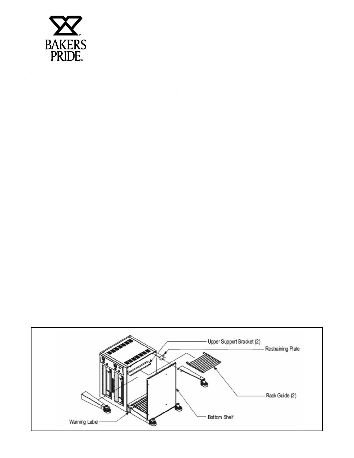
Optional Open Base Feature:
1. Install bottom shelf and rack guide brackets when
installing legs -while oven is on it’s side. Refer to
leg instructions in Installation/Operation Manual.
2. Attach two rack support brackets to base of oven
with three screws each bracket.
3. Install two legs to lower (left) side of oven. Align
and attach bottom shelf to these legs with a bolt
and locking nut -One each in the front and back.
4. Attach last two legs.
4
Page 7
COUNTERTOP ELECTRIC PIZZA OVEN OPERATION MANUAL
INSALLATION INSTRUCTIONS
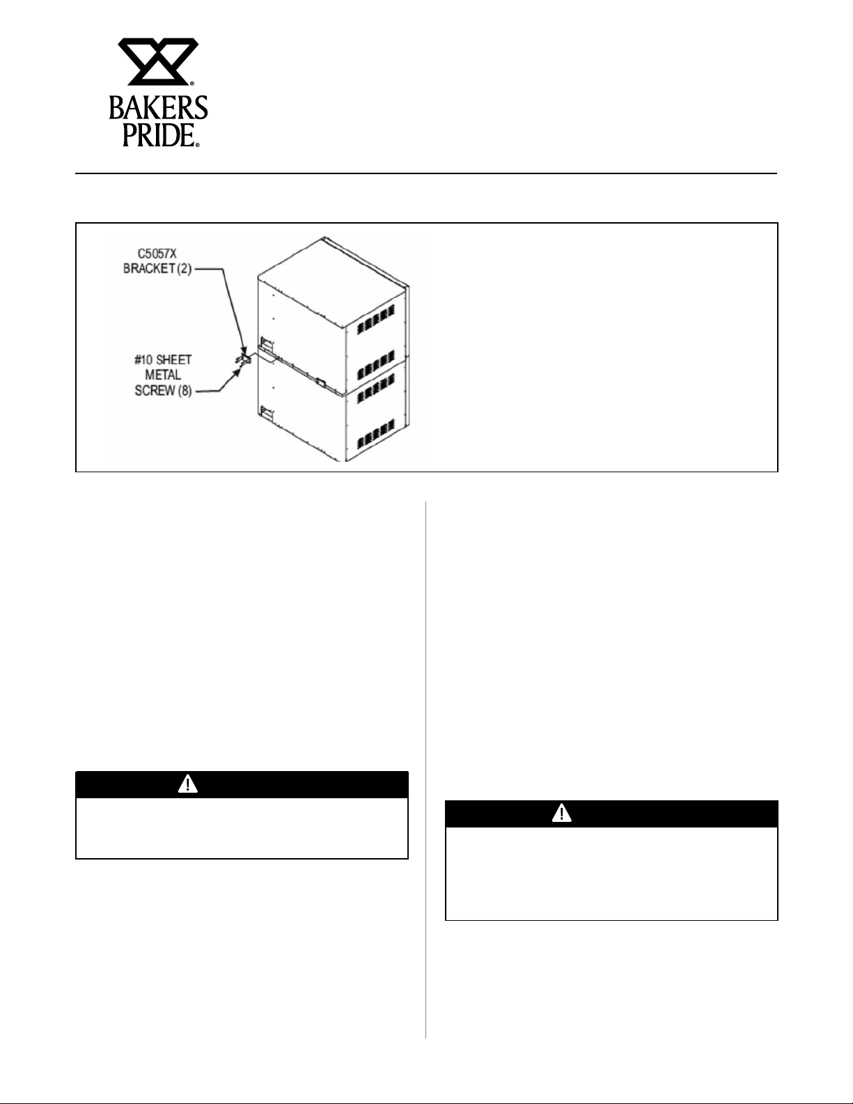
Double Stacked Ovens
Your EP/EB-1-2828 or EP/EB-2-2828 may
be stacked two ovens on top of one another.
In order to ensure the ovens do not slide
or separate, there is a stacking bracket kit
required for installation at the rear of the
ovens. Two brackets are installed, one at
each end of the oven securing the upper
oven to the bottom oven. Refer to the
adjacent illustration.
5. Attach bottom shelf to remaining two legs with two
bolts and locking nuts - One each in the front and
back.
6. When the oven is stood up, before moving it to
it’s final location, install four remaining bolts and
locking nuts to the legs -Two on left side, two on
right side. Tighten all.
7. Install two rack guides. Align the bottom pegs to
holes in the bottom shelf. Align top hooks to cutouts in upper support bracket. Lower into position.
8. Align oven racks (order separately) to the shelf
heights desired and slide into place.
Electrical Connections
WARNING
Risk of electrical shock. Appliance must be
secured to building structure.
1. Installation must be performed by licensed
electrician.
4. Connection to the electrical service must be
grounded in accordance with local codes. In
the absence of local codes refer to the National
Electric Code, ANSI/NFPA 70 or the Canadian
Electric Code, CSAC22.2 as applicable.
5. Only bare copper conductors with a minimum
insulation temperature rating of 90°C to be used.
6. The installer must supply a properly sized strain
relief bushing for the mains connection that meets
7. The oven shall be installed using flexible conduit.
8. The restraint cord must be securely attached to
the rear of the oven and to the building structure
to prevent transmitting unnecessary stress to the
flexible conduit.
CAUTION
Disconnect all ovens from electrical supply before
servicing. Connection is accessed by removing the
right side cover. Field connections are located at
the lower rear corner of the control compartment.
2. A separate electrical connection to the mains must
be provided for each oven.
3. An all pole disconnect must be provided by the
installer.
5
Page 8

COUNTERTOP ELECTRIC PIZZA OVEN OPERATION MANUAL
INSTALLATION INSTRUCTIONS
Explanation Of Controls
The oven has a main power switch at the bottom portion
of the control panel. This switch must be on for the
oven to operate. When switched to the ON position the
lamps in each cavity light.
Each cavity has separate temperature controls. The
thermostat dial may be adjusted from 200°F (100ºC) to
700°F (370ºC).
Heat Selector Switches:
To better control the ratio of Top and Bottom Heat, these
ovens have two heat selector switches, one controlling
the Top Heat, the other controlling the Bottom Heat.
Each allows a setting from #1 (low = 20% on/80% off)
through #9 (80% on/20% off) to #10 (high = 100% on).
In order to maximize the potential of the oven and to get
maximum power, both heat selector switches should be
set to #10 (high). This will be the best setting most of the
time for most of the products. However, if, after some
experimenting, one of the two proves to be too hot, only
that one should be reduced while the other one stays on
high. There is no need to reduce both at the same time. If
less heat is required, lower the thermostat setting.
b) Press both steam switches simultaneously. The red
indicator lamp will illuminate, the solenoid coil
will be activated and the solenoid valve will open
and allow steam to enter the baking chamber
for the duration of the selected time. After that
period, the power to the red indicator lamp and
solenoid coil will be cut off and the solenoid valve
will shut down the flow of steam to the oven.
WARNING
Never open the door while the red indicator lamp
is on and steam is being injected into the oven,
since exposure to Iive steam can cause serious
injuries.
Each cavity has a timer that may be used when cooking
product. The timer DOES NOT control the oven. To
set a cook time turn the dial clock-wise to the desired
setting. The timer will count down until the time expires.
A buzzer will sound continuously until the dial is turned
to the “OFF” position slightly to the left of “0”.
Ovens with Steam Option:
Never activate the steam timer when the oven is cold,
since the steam will immediately condense and turn to
water.
a) The steam timer can be adjusted from 1 to 60
seconds and has been factory set for 3-5 seconds.
To change this time, insert a small screw driver
through the 1/4” diameter hole below the steam
switches and turn the timer shaft clock-wise to
increase or counter-clockwise to decrease this
time delay setting.
Hook-Up
Control Panel: E-1-2828 Control Panel: E-2-2828
6
Page 9

COUNTERTOP ELECTRIC PIZZA OVEN OPERATION MANUAL
INSTALLATION INSTRUCTIONS
Usage Recomenations
1. Pre-heat the oven thoroughly before use. Allow one
hour and fifteen minutes for pre-heat.
2. Pre-heat ovens @ 75°F (24°C) BELOW desired
cook/bake temperature.
3. Do not move baking location in the middle of a
bake, but spinning is okay.
4. Keep decks clean of flour, cheese, etc using a deck/
scraper brush.
5. During idle periods, reduce heat by 75°F (24°C).
6. Minimize water content of products for faster cook/
bake times.
7. For larger & thick products, reduce temperature &
increase bake/cook time.
8. Cooking times and temperatures will vary depending
9. Keep a record of the times, temperature and load
sizes you establish for various products. Once you
have determined these, they will be similar for
succeeding loads.
10. When practical, start cooking the lowest
temperature product first and gradually work up to
the higher temperatures.
11. When loading the oven, work as quickly as possible
to prevent loss of heat.
12. Oven will continue to heat even though the timer
goes off. Product should be removed from the oven
as soon as possible to avoid overcooking.
13. When baking, weigh or measure the product in each
pan to assure even cooking.
14. Only bread and pizza may be placed directly on a
stone baking hearth.
upon such factors as size of the load, temperature,
mixture of products (particularly moisture) and
density of products.
Troubleshooting
There are no user serviceable components behind the covers. Contact your service agent.
Problem Probable Cause Remedy
Indicator light is out Set temperature has been reached. Take no action. The thermostat has turned off the power to the heat
The top and bottom heat control switches are “OFF”. Turn switches to a position other than “OFF”. This will allow indicator
Power supply fuses or circuit breakers are blown or
have been tripped.
No power Power supply fuses or circuit breakers are blown or
Oven too hot Thermostat set too high. Lower the thermostat setting. Allow several hours for heat to regulate
Bottom of pies are
Undercooked
Bottom of pies burn
before toppings are
cooked
Pies cook unevenly
have been tripped.
No power to oven. Check supply voltage.
High temperature thermostat tripped. Reset and check oven for fault condition.
Thermostat may be deffective. Call local authorized Bakers Pride service agent.
If the same area of the deck is used repeatedly, the
deck temperature in that area will be reduced.
Bottom switch set too low. Increase setting.
Top switch set too high. Decrease setting.
Deck temperature too hot - especially during slow
periods
Bottom switch set too high. Decrease setting.
Top switch set too low. Increase setting.
Areas adjacent to oven walls are generally hotter. Rotate pies (180°), once during each bake or keep to the center of oven.
Element defective Replace element
Heat selector switch faulty Replace heat selector switch
switches, indicator and heating elements. When oven starts to cool, all
functions will be restored
lamps, contactors and heating elements to operate
Replace fuse or reset circuit breaker.
Replace fuse or reset circuit breaker.
Rotate pies to unused areas of the bake deck that are hotter and will cook
the bottoms faster.
Reduce Thermostat setting by 50°-75° below normal bake temperature.
When decks cool begin cooking and immediately increase the thermostat
setting by 50° - 75°.
7
Page 10

COUNTERTOP ELECTRIC PIZZA OVEN OPERATION MANUAL
OPERATING INSTRUCTIONS
Cleaning
WARNING
Risk of electrical shock. Appliance must be
secured to building structure.
When the oven is new, operate it for at least one hour
at a setting of at least 500°F (250ºC). Due to normal
manufacturing processes, a small amount of steam and/
or smoke will exit the oven from moisture and oils on the
oven components. Shut off and allow the oven to cool.
After cooling wipe down the interior of the oven with
a clean damp cloth. Brushing of the baking hearth is
recommended.
Exterior Cleaning
It is recommended that a regular cleaning schedule be
maintained to keep your oven operating and looking its
best. Spills should be cleaned immediately.
The oven should always be allowed to cool sufficiently
before cleaning. Exterior surfaces should be wiped with
a soft cloth and mild detergent. Stubborn stains may be
cleaned with a light weight, non-metallic cleaning pad.
Apply only light pressure and rub in the direction of the
surface grain.
The control panel surface is easily cleaned with a soft
cloth and mild detergent. Do not use abrasives, solvent
cleaners or metallic scouring pads on the control panel.
They may scratch or damage the label surface.
Never spray steam or water directly onto or into the
oven. This could adversely affect the ceramic cooking
hearth and/or electrical components.
Do not use oven cleaners, caustic solutions or
mechanical means that may damage the interior of your
oven.
Maintenance
Users are cautioned that maintenance and adjustments
should only be performed by authorized service agents
using Bakers Pride replacement parts.
Minor periodic maintenance to your oven should provide
many years of useful service to you. Any time the unit is
serviced it is recommended all components be checked
and their performance verified. At least once each year
your oven should be inspected by a qualified service
provider to insure your oven is operating at its peak
performance.
Replacement Parts
Enclosed in this booklet are diagrams of likely
replacement parts that may be required for normal
maintenance. Specifications are subject to change
without notice. Be sure to verify the current specification
with your qualified service provider or Bakers Pride
before ordering replacement parts.
Wiring Diagrams
The current wiring diagram at the date of your oven’s
manufacture was affixed to the unit for reference.
Copies of the proper wiring diagrams effective on the
date this booklet is printed are enclosed. Specifications
are subject to change without notice. If there is any
uncertainty or discrepancy between the wiring diagram
and your oven refer to Bakers Pride Technical Service
for clarification.
Interior Cleaning
Internal metallic surfaces should be allowed to cool
before cleaning. Wipe interior surfaces with a wet cloth
or light weight scouring pad.
Food particles or spills that accumulate on the baking
hearth may be brushed off with a normal oven brush.
Stubborn spills should be heated to a maximum
temperature for approximately one hour to burn the spill
so it will crumble and easily brush out afterwards.
8
Page 11

COUNTERTOP ELECTRIC PIZZA OVEN OPERATION MANUAL
OPERATING INSTRUCTIONS
Exploded View & Parts List
Exploded View: EP-1 & EP-2-2828
9
Page 12

COUNTERTOP ELECTRIC PIZZA OVEN OPERATION MANUAL
OPERATING INSTRUCTIONS
Item Part No. Description
1 C4075X Spring Adjustment Bracket
2 C5078K Outer Back (EP-1)
C5018K Outer Back (EP-2)
3 C5082K Outer Side (EP-1)
C5019K Outer Side (EP-2)
4 C5020K Outer Top
5 C5094K Component Panel (EP-1)
C5025K Component Panel (EP-2)
6 C5027X Door Stop Angle
7 Q2301X Bolt 3/8 – 16x1 Hx Hd
8 C5035X Steel Hearth (Baking Deck)
9 C5040X Door Assembly - Solid
10 C5041X Door Assembly - Wood
11 C5050X Door Hinge Assembly
12 C5055X Door Handle Assembly
13 C5056X Door Stop Angle
14 C5080K Control Panel (EP-1)
C5058K Control Panel (EP-2)
15 L1193A Lower Element – 230V 750W
L1194A Upper Element – 230V 500W
L1196A Lower Element – 208V 750W
L1197A Upper Element – 208V 500W
L1199A Lower Element – 240V 750W
L1200A Upper Element – 240V 500W
L1202A Lower Element – 460V 750W
L1203A Upper Element – 460V 500W
16 L1195A Front Element – 230V 750W
L1198A Front Element – 208V 750W
L1201A Front Element – 240V 750W
L1204A Front Element – 460V 750W
17 M1352X Switch, Rocker, Green
18 M1376A Transformer, 480/240V 0.25KVA
19 M1367X Infinite Switch – 208V (EGO)
M1368X Infinite Switch – 230V (EGO)
20 M1371A Contactor, 208V, 25A, 4Pole, 50/60Hz
M1372A Contactor, 240V, 25A, 4Pole, 50/60Hz
21 M1382X Timer - 60 Minute
M1384X Timer - 15 Minute
22 M1481X Thermostat, 400°C
23 M1482X Thermostat, Hi-Limit
24 P1025X Ground Lug
25 P1045X Snap Bushing, 2”
26 C1074X Wire Clamp
27 P1098X Terminal Block
28 P1145A Light Assy, 240v-15w Snap-in
29 P1150A Din Rail, 4-1/4” (EP-1)
30 P1210E Din Rail, 8-1/2” (EP-1)
31 U4168A Manual, Installation/Operation
Item All Models Description
32 S1062A Terminal Cap, 10-32
33 S1306X Knob, Rotary Sw, w/Brass Insert (w/M1282A)
34 S1311S Knob, Thermostat/Timer, Alum. Inlay
35 S1403X Knob, 1-1/4”
36 S1404A Glass, Door Window, 4”x20”
37 S3004X Spring, Door, 13/16”x6-3/4”
38 S3007X Spring Bushing, PTFE
39 S3271X Door Hinge Bushing
40 S6064X Door Seal
41 T1287X Baking Deck, Ceramic, 27-3/4” x 27-3/4” x 3/4”
42 S1050U Legs, 30”
43 S1310U Legs, 16”
44 S1014X Legs, 4”
45 S1022X Caster, 4”, No Lock (ea.)
46 S1023X Caster, 4”, With Lock (ea.)
47 U1043A Nameplate – Bakers Pride, 13-1/4”
48 U1057A Label, 4 Block Wiring
49 U1183A Label, Ground Symbol
50 U1192A Caution Hot Label, Bi-Lingual
51 U1240A Label, Unit for use only with…
52 U1257A Label, International Symbol
53 U1333A Label, Warning (pizza Oven/Cordierite)
54 U1364A Label, Warning
55 U1448X Overlay – No Timer (EP – 1)
U1445X Overlay – No Timer (EP – 2)
U1439X Overlay – 15 Minute Timer (EP – 1)
U1442X Overlay – 15 Minute Timer (EP – 2)
U1440X Overlay – 60 Minute Timer (EB – 1)
U1443X Overlay – 60 Minute Timer (EB – 2)
U1441X Overlay – 60 Minute Timer w/Steam (EB – 1)
U1444X Overlay – 60 Minute Timer w/Steam (EB – 2)
N/S C5057K Stacking Bracket, ea (2 req’d)
N/S C5033K Element Support Bracket
N/S C5044K Glass Retainer
N/S S6073A Ceramic Fiber Strip, Adhesive, (1”x25’)
N/S T8085T Open Rack Stand (w/o 30” legs)
Steam Components
N/S` C5096X Valve Assy, Union to Union, EB – 1 (Steam)
N/S C5097X Valve Assy, Union to Union, EB – 2 (Steam)
N/S C4161K Solenoid Bracket (Steam)
N/S M1387A Solenoid Valve, 1/2B, 1/2P (Steam)
N/S M1388A Solenoid Coil, 208-240V, 50/60HZ (Steam)
60 M1176A Potentiometer (Steam)
61 M1231A Timer, Solid State (Steam)
62 C5093K Control Bracket (Steam)
63 P1098A Push Button Switch (Steam)
64 P1168A Indicator Lamp, Red (Steam)
Note: When ordering parts, ALWAYS specify Part Number, Model Number, Serial Number, and Voltage/Phase.
10
Page 13

COUNTERTOP ELECTRIC PIZZA OVEN OPERATION MANUAL
OPERATING INSTRUCTIONS
Wiring Diagrams
Wiring Diagram: EP-2-2828, 208-240V, 1Ph or 3Ph
11
Page 14

COUNTERTOP ELECTRIC PIZZA OVEN OPERATION MANUAL
OPERATING INSTRUCTIONS
Wiring Diagram: EP-2-2828, 230-400V, 1Ph or 3Ph
12
Page 15

COUNTERTOP ELECTRIC PIZZA OVEN OPERATION MANUAL
OPERATING INSTRUCTIONS
Wiring Diagram: EP-2-2828, 480V, 1Ph or 3Ph
13
Page 16

COUNTERTOP ELECTRIC PIZZA OVEN OPERATION MANUAL
OPERATING INSTRUCTIONS
Wiring Diagram: EP-1-2828, 208-240V, 1Ph or 3Ph
14
Page 17

COUNTERTOP ELECTRIC PIZZA OVEN OPERATION MANUAL
OPERATING INSTRUCTIONS
Wiring Diagram: EP-1-2828, 230-40 0V, 1Ph or 3Ph
15
Page 18

COUNTERTOP ELECTRIC PIZZA OVEN OPERATION MANUAL
BAKERS PRIDE LIMITED WARRANTY
WHAT IS COVERED This warranty covers defects in material and workmanship under normal use, and applies only to the original purchaser
• The equipment has not been accidentally or intentionally damaged, altered or misused;
• The equipment is properly installed, adjusted, operated and maintained in accordance with National
• The serial number rating plate affixed to the equipment has not been defaced or removed.
WHO IS COVERED This warranty is extended to the original purchaser and applies only to equipment purchased for use in the U.S.A.
COVERAGE PERIOD Cyclone Convection Ovens: BCO Models: One (1) Year limited parts and labor; (1) Year limited door warranty.
GDCO Models: Two (2) Year limited parts and labor; (2) Year limited door warranty.
CO11 Models: Two (2) Year limited parts and labor; (5) Year limited door warranty.
All Other Products: One (1) Year limited parts and labor. Warranty period begins the date of dealer invoice to customer
WARRANTY This warranty covers on-site labor, parts and reasonable travel time and travel expenses of the authorized service
COVERAGE Representative up to (100) miles, round trip, and (2) hours travel time. The purchaser, however, shall be responsible for
EXCEPTIONS All removable parts in Bakers Pride
providing that:
and local codes and in accordance with the installation instruction provided with the product;
or ninety (90) days after shipment date from Bakers Pride - whichever comes first.
all expenses related to travel, including time, mileage and shipping expenses on smaller counter models that may be
carried into a Factory Authorized Service Center, including the following models: PX-14, PX-16, P18, P22S, P24S, PD-4,
PDC, WS Series and BK-18.
®
and Valves, are covered for a period of SIX MONTHS. All Ceramic Baking Decks are covered for a period of THREE
MONTHS. The installation of these replacement decks is the responsibility of the purchaser. The extended Cyclone door
warranty years 3 through 5 is a parts only warranty and does not include labor, travel, mileage or any other charges.
cooking equipment, including but not limited to: Burners, Grates, Radiants, Stones
EXCLUSIONS
INSTALLATION Leveling and installation of decks as well as proper installation and check out of all new equipment —per appropriate
REPLACEMENT PARTS Bakers Pride genuine Factory OEM parts receive a (90) day materials warranty effective from the date of installation by a
This Warranty is in lieu of all other warranties, expressed or implied, and all other obligations or liabilities on the manufacturer’s part. Bakers Pride
shall in no event be liable for any special, indirect or consequential damages, or in any event for damages in excess of the purchase price of the unit.
The repair or replacement of proven defective parts shall constitute a fulfillment of all obligations under the terms of this warranty.
• Negligence or acts of God,
• Failures caused by erratic voltages or gas supplies,
• Thermostat calibrations after (30) days from
equipment installation date,
• Unauthorized repair by anyone other than a Bakers
Pride Factory Authorized Service Center,
• Air and Gas adjustments,
• Damage in shipment,
• Light bulbs,
• Alteration, misuse or improper installation,
• Glass doors and door adjustments,
installation and use materials — is the responsibility of the dealer or installer, not the manufacturer.
Bakers Pride Factory Authorized Service Center.
• Thermostats and safety valves with broken capillary
tubes,
• Fuses,
• Char-broiler work decks and cutting boards,
• Tightening of conveyor chains,
• Adjustments to burner flames and cleaning of pilot
burners,
• Tightening of screws or fasteners,
• Accessories — spatulas, forks, steak turners, grate
lifters, oven brushes, scrapers, peels. etc.,
• Freight — other than normal UPS charges,
• Ordinary wear and tear.
16
Page 19

IMPORTANT FOR FUTURE REFERENCE
Please complete this information and retain this manual for the life of the equipment. For Warranty Service and/or
Parts, this information is required.
Model Number Serial Number Date Purchased
NOTES
17
Page 20

NOTES
18
Page 21

NOTES
19
Page 22

Food Service Equipment Group
The Standex Food Service Equipment Group (FSEG) is a manufacturer of innovative commercial food
service equipment offering a wealth of refrigeration and cooking expertise. Products include walk-in
coolers and freezers; hot and cold display cabinets, cases, and storage systems; commercial ovens,
rotisseries, and cooking equipment; and rotary vane pumps.
Ask your sales representative about how the power of all Standex brands can work for you.
www.standex.com/segments/food-service
Be sure to keep up with new product announcements
and events on social media!
 Loading...