

Page 1
Installation & Operation Manual
BAKERS PRIDE
®
E300 SPEED OVEN
Page 2
INSTALLATION AND OPERATING INSTRUCTIONS
Bakers Pride® E300 Speed Oven
INTENDED FOR OTHER THAN HOUSEHOLD USE RETAIN
THIS MANUAL FOR FUTURE REFERENCE OVEN MUST BE
KEPT CLEAR OF COMBUSTIBLES AT ALL TIMES
WARNING: Improper installation, adjustment, alteration, service or maintenance can cause
property damage, injury or death. Read the installation, operating and maintenance instructions
thoroughly before installing or servicing this equipment.
Cooking Solutions Group
This equipment has been engineered to provide you with year round dependable service when
used according to the instructions in this manual and standard commercial kitchen practices.
Bakers Pride Oven Company, LLC is a wholly owned subsidiary of Standex International Corporation.
IMPORTANT FOR FUTURE REFERENCE
Please complete this information and retain this manual for the life of the equipment.
For Warranty Service and/or Parts, this information is required.
Model Number Serial Number Date Purchased
1307 N. Watters Road
Suite 180, Allen, TX 75013
9/18
www.bpspeedoven.com
www.bakerspride.com
western@standexcsg.com
central@standexcsg.com
eastern@standexcsg.com
800.527.2100
972.908.6100
Cooking Solutions Group
Page 3
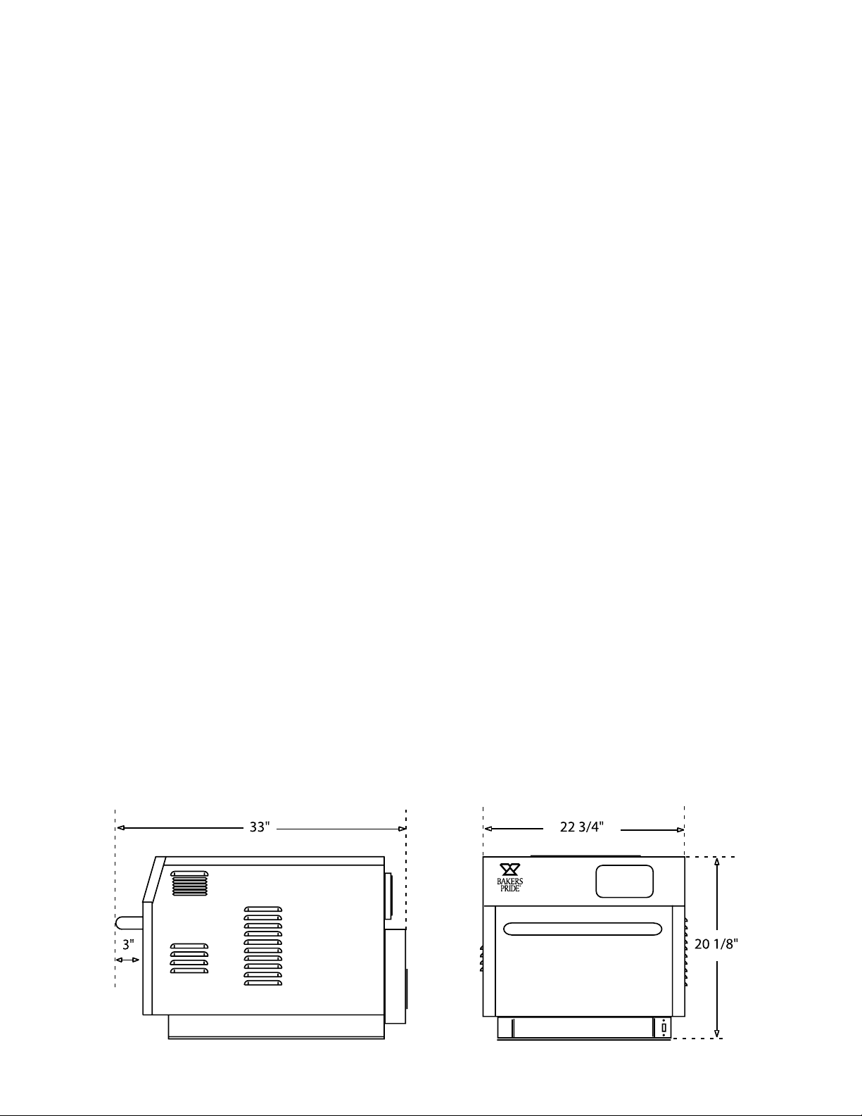
Table of Contents
Safety Information
Microwave Exposure Precautions 4
General Safety Information 5
General Safety Information - French 6
Installation Information
Receiving 7
Set Up 7
Minimum Clearances 8
Electrical Connections 8
Cleaning And Maintenance
Catalytic Converter 9
Cook Rack And Jetplates 9
Oven Cavity 10
Oven Maintenance Guidelines 10
Oven Programming
Home Screen - Cook Screen 11
Cook Screen - Resume Screen 11
Menu Set Up Screen - Group Edit Screen 13
Item Edit Screen 14
System Set Up - Manager Settings Screen 15
Oven Statistics - Controller Settings - Menu File Screens 16
Wiring Diagrams
E300 17
Exploded Views 18
Service Parts
Part Numbers 20
Limited Warranty Information 21
Page 4
Safety Information
FOR YOUR SAFETY: Not For Built-In Installation. For Use Only In Professionally Staffed Commercial
Kitchens. Not For Use In Areas Accessible To The General Public.
FOR YOUR SAFETY: Do not store or use gasoline or other flammable vapors or liquids in the vicinity of
this or any other appliance.
WARNING: Improper installation, adjustment, alteration, service or maintenance can cause property
damage, injury or death. Read the Installation, Operating and Maintenance Instructions thoroughly
before installing or servicing this equipment.
WARNING: Initial heating of oven may generate smoke or fumes and must be done in a well-ventilated
area. Overexposure to smoke or fumes may cause nausea or dizziness.
WARNING: To provide continued protection against electric shock, connect to properly grounded outlets
only.
CAUTION: This Device is to be Serviced Only by Properly Qualified Service Personnel. Consult the
Service Manual for Proper Service Procedures to Assure Continued Compliance With the Federal
Performance Standard for Microwave Ovens and for Precautions to be Taken to Avoid Possible Exposure
to Excessive Microwave Energy.
WARNING: Risk of electric shock. Non-removable fasteners are provided because of internal high
voltages. Do not remove fasteners.
California Residents Only. This product can expose you to chemicals including chromium which is
known to the State of California to cause cancer and birth defects or other reproductive harm. For more
information go to www.P65Warnings.ca.gov.
PRECAUTIONS TO AVOID POSSIBLE EXPOSURE
TO EXCESSIVE MICROWAVE ENERGY
(a) Do not attempt to operate this oven with the door open since open-door operation can
result in harmful exposure to microwave energy. It is important not to defeat or tamper
with the safety interlock switches.
(b) Do not place any object between the oven front face and the door or allow soil or
cleaner residue to accumulate on sealing surfaces.
(c) Do not operate the oven if it is damaged. It is particularly important that the oven door
close properly and that there is no damage to the: (1) Door (bent), (2) hinges and
latches (broken or loosened), (3) door seals and sealing surfaces.
(d) The oven should not be adjusted or repaired by anyone except properly qualified
service personnel.
4
Page 5

Safety Information
• Read all instructions before using the appliance
• Read and follow the specific PRECAUTIONS TO AVOID POSSIBLE EXPOSURE TO EXCESSIVE MICROWAVE
ENERGY located on page 4 of this manual.
• This appliance must be grounded. Connect only to a properly grounded outlet. See GROUNDING INSTRUCTIONS
located on page 8 of this manual.
• Install or locate this appliance only in accordance with the provided installation instructions.
• Some products like whole eggs and sealed containers - for example, closed glass jars - are able to explode and
should not be heated in this oven.
• Use this appliance only for its intended use as described in the manual. Do not use corrosive chemicals or vapors
in this appliance. This type of oven is specifically designed to heat, cook, or dry food. It is no designed for industrial
or laboratory use.
• As with any appliance, close supervision is necessary when used with children.
• Do not operate this appliance if it has a damaged cord or plug, if it is not working properly, or if its been damaged
or dropped.
• This appliance should be serviced only by qualified service personnel. Contact the nearest authorized service
facility for examination, repair, or adjustment.
• Do not cover or block any openings on the appliance.
• Do not store this appliance outdoors. Do not use this product near water - for example, near a kitchen sink, in a
wet basement, near a swimming pool, or similar location.
• Do not immerse cord or plug in water.
• Keep cord away from heated surfaces.
• Do not allow cord to hang over edge of table or counter.
• When cleaning surfaces of door and oven that meet when the door closes, use only mild, nonabrasive soaps, or
detergents applied with a sponge or soft cloth.
• To reduce the risk of fire in the oven cavity:
i) Do not over cook food. Carefully attend appliance when paper, plastic, or other combustible materials are
placed inside the oven to facilitate cooking.
ii) Remove wire twist-ties from paper or plastic bags before placing bag in oven.
iii) If materials inside the oven ignite, keep the oven door closed, turn the oven off, and disconnect the
power cord, or shut the power off at the circuit breaker panel.
iv) Do not use the cavity for storage purposes. Do not leave paper products, cooking utensils, or food in the
cavity when not in use.
• Liquids, such as water, coffee, or tea are able to be overheated beyond the boiling point without appearing to be
boiling.
• Visible bubbling or boiling is not always present when the container is removed from the microwave oven. THIS
COULD RESULT IN VERY HOT LIQUIDS SUDDENLY BOILING OVER WHEN THE CONTAINER IS DISTURBED
OR A UTENSIL IS INSERTED INTO THE LIQUID.
5
Page 6

Consignes De Sécurité Importantes
Lors de l'utilisation d'appareils électriques précautions de sécurité de base doivent être respectées, y compris ce qui suit:
AVERTISSEMENT - Pour réduire les risques de brûlure, électrocution, d'incendie, de blessure ou d'exposition à l'énergie micro-ondes
excessive:
• Lisez toutes les instructions avant d'utiliser l'appareil.
• Lire et suivre les précautions spécifiques “POUR ÉVITER UNE EXPOSITION EXCESSIVE AUX MICRO-ONDES” (Situé ci-dessous et
page suivante).
• Cet appareil doit être mis à la terre. Connectez seulement à une prise de terre. Voir “INSTRUCTIONS DE MISE” trouvés sur la page
8.
• Installer ou placer l'appareil conformément aux instructions d'installation fournies.
• Certains produits comme les œufs entiers et des contenants scellés - par exemple, bocaux en verre fermés - peuvent exploser et ne
devraient pas être chauffés dans ce four.
• Utilisez cet appareil uniquement pour son usage prévu comme décrit dans le manuel. Ne pas utiliser de produits chimiques corrosifs
dans cet appareil. Ce type de four a été spécialement conçu pour chauffer, cuire ou sécher des aliments. Il n’est pas conçu pour un
usage industriel ou de laboratoire.
• Comme pour tout appareil, une surveillance étroite est nécessaire quand il est utilisé par les enfants.
• Ne pas utiliser cet appareil si le cordon ou la fiche est endommagé, s'il ne fonctionne pas correctement, ou si elle a été endommagée
ou supprimée.
• Cet appareil ne doit être effectué que par du personnel qualifié. Contactez le centre de service agréé le plus proche pour examen,
réparation ou réglage.
• Ne pas couvrir ou bloquer les ouvertures de l’appareil.
• Ne pas stocker cet appareil à l'extérieur. Ne pas utiliser ce produit près de l'eau - par exemple près d' un évier de cuisine , dans un
sous-sol humide , près d’une piscine , ou des endroits similaires .
• Ne pas immerger le cordon ou la fiche dans l’eau.
• Garder le cordon loin des surfaces chauffées.
• Ne laissez pas le cordon pendre de la table ou du comptoir.
• Lors du nettoyage de surfaces de la porte et du four qui se réunit à la fermeture de la porte , utilisez uniquement douces , savons
non abrasifs ou de détergents appliqués avec une éponge ou un linge doux
• Afin de réduire le risque d'incendie dans la cavité du four :
a. Ne pas trop cuire les aliments. Surveillez attentivement votre four lorsque du papier , du plastique ou d’autres matériaux
combustibles sont placés à l’intérieur du four pour faciliter la cuisson .
b. Retirer les attaches de sacs en papier ou en plastique avant de les placer dans le four.
c. Si les matériaux à l'intérieur du four prennent feu, garder la porte du four fermée , éteindre le four et débranchez le
cordon d’ alimentation ou coupez le courant au fusible ou panneau de disjoncteurs .
d. Ne pas utiliser la cavité à des fins de stockage. Ne laissez pas de produits en papier, ustensiles de cuisine, ou de la
nourriture dans la cavité lorsqu’il n’est pas utilisé.
• Les liquides tels que l’eau, le café ou le thé peuvent être surchauffés au-delà du point d'ébullition sans sembler bouillir. Bullage ou
ébullition visible lorsque le récipient est retiré du four à micro-ondes ne sont pas toujours présents. CELA POURRAIT PROVOQUER
DES LIQUIDES TRÈS CHAUDS SOUDAIN bouillante sur lorsque le récipient est perturbé ou un ustensile est inséré dans le LIQUIDE
Avertissement: Pour assurer une protection continue contre les chocs électriques, se connecter à des
prises correctement mise à la terre
ATTENTION: Cet appareil doit être réparé que par du personnel qualifié de service. Consultez le manuel
d’entretien pour les procédures de service appropriées pour assurer la conformité continue avec
la norme fédérale performance pour Micro-ondes et pour les précautions à prendre pour éviter une
éventuelle exposition excessive à micro-ondes de l’énergie
AVERTISSEMENT: Risque de choc électrique. La non-fixation amovibles sont prévus en raison de fortes
6
tensions internes. Ne pas retirer les attaches.
Page 7

Installation Information
Receiving
Read the notice on the outside carton regarding damage in transit. Damage discovered after opening the carton is
“CONCEALED DAMAGE.” Carrier must be notified immediately to send an inspector and to furnish forms for claims
against the carrier.
When the oven arrives, it should consist of:
• One Peel
• One PTFE Solid Basket
• One PTFE Perforated Mesh Basket
• 2 oz Cleaner
• 2 oz Shield
• Installation & Operation Manual
• A crate or carton containing your new oven.
When unpacking the oven:
• Remove all packing material from unit
• Never lift the oven with only one person
• Retain instruction manual for future reference
• Never lift oven by the handle
Set Up/Mounting
Your oven will be packed sitting on its bottom. The skid may be left under the oven for convenience in further
handling. Unpack carefully, avoiding damage to the Stainless Steel front and/or trim. If concealed damage is found,
follow the instructions detailed in the Receiving section above.
• Keep the area around the ovens free and clear of combustible materials.
• Do not store any materials on top of or under any oven.
• Do not position the unit so that hot air is drawn in from fryers, grill, griddles or other appliances.
• A heat barrier the height of the oven will be required if installed by a burner, fryer, or excessive heat source.
• Adequate air supply to the oven for ventilation is essential. As a minimum, observe the clearances detailed on page
8 (Minimum Clearances and Approved Locations). Provide adequate ventilation and make up air in accordance
with local codes.
• The intake air is located on the left and right sides at the front of the oven. To prevent deteriorating the life and
performance of the oven the intake air should be as cool as possible and not preheated by other appliances.
• Allow sufficient clearance in front of the unit for the door to open completely.
NOTICE: Local codes regarding installation vary greatly from one area to another. The National Fire
Protection Association, Inc., states in its NFPA 96 latest edition that local codes are the “authority
having jurisdiction” when it comes to requirements for installation of equipment. Therefore, installations
should comply with all local codes.
This unit is supplied with a closed cell pad that will seal the unit to the counter top. When using the closed cell foam
pads for final installation, the edges of the pad must be sealed with an FDA/NSF approved silicone sealant after the
unit is placed into position. This unit can also be used with optional 4” legs to by-pass FDA/NSF requirements.
The ovens are designed to be stackable at a maximum height of two units. To stack two units, use the foam pad
provided. Remove the center section of the pad before placing on the bottom oven to allow a more stable installation.
Proper lifting methods must be used for safety. Each oven must have a dedicated power supply. (If the leg option
is used for a stackable installation, only the bottom oven receives the legs, the foam pad must be used between
ovens).
7
Page 8
Installation Information
NOTICE: Local codes regarding installation vary greatly from one area to another. The National Fire
Protection Association, Inc., states in its NFPA 96 latest edition that local codes are the “authority
having jurisdiction” when it comes to requirements for installation of equipment. Therefore, installations
should comply with all local codes.
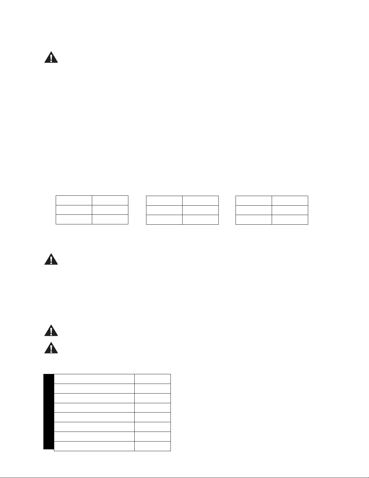
Minimum Clearances and Approved Locations
Move the oven to its final location keeping the minimum clearance from the back of the oven to the wall. This
clearance is necessary for safe operation and to provide proper air flow.
The oven is designed for countertop installation and is not recommended for built-in installation. The oven requires
adequate air to cool the electronic controls. Operating the oven at elevated temperatures may reduce reliability and
overall performance of the oven.
If the oven is to be installed close to a major heat source including char grills, griddles and fryers, minimum
clearances must be observed and a radiant/thermal heat barrier installed between the heat source and the oven.
Adequate access to electrical connections, and side panels must be provided for any future service. The operator
may be responsible for any additional labor fees if required.
Minimal Clearances from Combustible and Noncombustible Construction
Sides 2 Inches
Rear 2 Inches
Top 2 Inches
No Surrounding Heat Source
CAUTION: Do not set the oven with its back flat against the wall. It will not operate properly unless there
is at least two inches breathing space behind the oven.
Sides 6 Inches
Rear 2 Inches
Top 2 Inches
Minor Surrounding Heat
Source; e.g. Heat Lamps & Warmers
Sides 12 Inches
Rear 2 Inches
Top 2 Inches
Major Surrounding Heat Source;
e.g. Fryers, Grills & Griddles
Electrical Connection
Install according to the spacing requirements listed in the installation section of this manual. We strongly
recommend having a competent professional install this equipment. A licensed electrician should make the
electrical connections and connect power to the unit. Local codes should always be used when connecting these
units to electrical power. In the absence of local codes, use the latest version of the National Electrical Code.
CAUTION: This Appliance Must be Grounded. Failure to do so May Result In Electrical Shock and Death.
CAUTION: The oven, when installed, must be electrically grounded in accordance with local codes and/
or the latest edition of the National Electrical Code ANSI/NFPA No. 70 in the USA (Canadian Electrical
Code CSA Standard C22.1, Part 1 in Canada).
VOLTAGE 208/240
FREQUENCY 60 HZ
SERVICE REQUIRED 30 AMP
PHASE SINGLE
TOTAL WATTAGE 5.4 kW
MAGNETRON WATTS 2.2 kW
MODEL E300
HEATER WATTAGE 3.2 kW
RECEPTACLE REQUIRED NEMA 6-30
8
Page 9

Cleaning and Maintenance
WARNING: Unit is not waterproof. To avoid electrical shock or personal injury, DO NOT submerge in
water. DO NOT operate if it has been submerged in water. DO NOT clean the unit with a water jet. DO NOT
steam clean or use excessive water on the unit.
CAUTION: Use mild detergent or soap solution for best results. Abrasive cleaners could scratch the
finish of your unit, marring its appearance and making it susceptible to dirt accumulation. DO NOT use
abrasive cleaners or a cleaner/sanitizer containing chlorine, iodine, ammonia or bromine chemicals as
these will deteriorate the stainless steel and glass material and shorten the life of the unit. Use nylon
scouring pads. Do not use steel wool.
Catalytic Converter
The oven utilizes a catalytic converter system that filters the cooking cavity air reducing grease and odors from the
room. This catalyst contains a microscopic layer of a specific compound that reduces the ignition temperature of
grease. When the cavity air is moved through the catalyst, the grease laden air is reduced to CO2 and H2O. The
catalyst is maintenance free and will continue to operate without issue through the life of the oven. However, proper
care is required when choosing the chemicals used to clean the cavity in order to ensure longevity.
The catalyst is sensitive to particular compounds found in common degreaser and industrial cleaners. Potassium
salts, phosphates, silicates, and other caustic compounds can cause irreversible damage. This damage can result in
reduced catalyst performance causing grease, smoke and odors to be in the room.
Bakers Pride provides an approved cleaner for purchase and recommends any alternatives be checked to determine
their chemical content so not to cause damage.
The catalyst is located directly behind the back wall and does not need to be removed for cleaning
Cook Rack
Open the door and remove the wire rack. Take rack to the sink and thoroughly clean in warm water with mild
detergent or soap. Use a nylon scouring pad or stiff nylon brush.
Do not use steel wool.
Lower Jetplate
Open the door and remove the wire cooking rack and remove lower jet plate by pushing back and lifting up on
the knob. Take the panel to the sink and thoroughly clean in warm water with mild detergent or soap. Use a nylon
scouring pad or stiff nylon brush.
Do not use steel wool.
Upper Jetplate
The upper jet plate may not need removed for daily cleaning. A simple wipe may be all that is needed based on
usage and product type.
Open the door and remove the upper jet plate by pushing back and pulling down on the knob. Take the panel to the
sink and thoroughly clean in warm water with mild detergent or soap. Use a nylon scouring pad or stiff nylon brush.
Do not use steel wool.
9
Page 10

Cleaning and Maintenance
Oven Cavity
With the door open, the rack and jet plate(s) removed, wipe out inside of the oven with a clean, damp cloth. Use a
nylon scouring pad dampened with approved cleaning chemical or stiff nylon brush to remove any baked on debris.
Use a clean towel dampened with clean water to thoroughly wipe out inside to remove any cleaner residue and food
particles.
Do not use steel wool.
Keep cleaning fluids away from electrical wires, light sockets, switches, and the control panel.
Oven Exterior
To remove common dirt or product residue from stainless steel, use ordinary soap and water (with or without
detergent) applied with a sponge or cloth. Dry thoroughly with a clean cloth. Never use vinegar or corrosive cleaner.
Do not use chlorine based cleaners.
To remove grease and food splatter or condensed vapors that have baked on the equipment, apply cleaners to a
damp cloth or sponge and rub cleanser on the metal in the direction of the polished lines on the metal. Rubbing
cleanser as gently as possible in the direction of the polished lines will not mar the finish of the stainless steel. To
remove discoloration, use a non-abrasive cleaner. NEVER use a wire brush, steel or abrasive scouring pads, scraper,
file or other steel tools. NEVER RUB WITH A CIRCULAR MOTION.
Oven Maintenance
NOTE: This appliance must be serviced by a factory authorized service agent. Unauthorized service or
repairs may void the manufacturers warranty.
• Power supply to the unit must be disconnected before any service is performed.
• Most of the service on this unit can be performed from the top and/or right side.
• It will be necessary to have access to the back of the oven for service needs related to the electric power supply.
However, for proper servicing, access to all sides is recommended.
• A system wiring diagram is provided in the back of this document as well as attached to the inside of the right side
oven panel.
• All servicing should be performed by a factory-authorized technician only.
• For proper maintenance and repairs, call the factory toll free (800.431.2745) for an authorized service agency in
your area.
CAUTION: This product, when stacked, has more than one power-supply connection point. Disconnect all
power supplies before servicing.
10
Page 11

Oven Programming
Home Screen
Open Door to Speed Cooling/Oven Temp = 187F
SERIAL NUMBER:
MANUFACTURED DATE:
SOFTWARE VERSION:
Oven is Cooling Down
Press Power Button to Turn On
Home Off Screen
• This screen will turn the oven power ON. Turning the
oven power OFF from subsequent screens will return
to this screen.
• This screen displays the manufactured date, serial
number of the unit and the current software versions
installed.
Cook Menu Setup System Setup Help
Bakers Pride SPEED COOKING
562071502001
02/15/15
GEMINI_DC_00.98
GEMINI_IO_00.05
11:20:45 AM
Friday, February 27
Cook Screen
Cook Menu Setup System Setup Help
Select Group
Vegetables
Hot Dog Pizza Wings
Back
Breakfast Dinner
Page 1 of 2
Cook Group Screen
• Pressing the COOK tab will show all the groups.
• Groups are menu categories that have sub categories
called items. Groups can be programed with
independent set cook temperatures.
• The program supports 16 groups with each group
having 24 items for a total of 384 possible recipes
stored in memory.
• Press the arrow buttons to move between pages.
• Press the BACK button to return to the Home ON
screen.
• Press the power icon to return to the Home OFF
screen.
French Fries
Quesadilla
Oven Warming Select Operation
Home On Screen
• After pressing the ON icon from the previous screen,
the oven will warm and display this screen.
• This Home ON screen displays the current time
and date and the message “Oven Warming Select
Operation”.
• This message will remain displayed until a function
tab is pressed.
• The oven will warm to the lowest group set point
temperature.
• Pressing the green OFF icon in the bottom right will
return to the Home OFF screen.
• Pressing the BACK key in any mode will eventually
return to this Home ON screen.
Set Point 500 F
Dinner
12%
80 F
Preheating Oven. Please wait...
Cancel
Pre Heat Screen
• After choosing a group, the oven must be at the set
temperature before the item screen is displayed.
• The screen displays the group name, set point and
actual cavity temperatures with a bar graph showing
progress.
• A pre heated oven will not display this screen.
11
Page 12

Oven Programming
Cook Screen
Selected Group: Dinner Selected Group: Dinner
Select Item
Add New
Potato
Back
Lasagna
Mac &
Cheese
Page 1 of 3
Fish Sticks Hamburger
Shrimp
Egg Roll
Cook Item Screen
• After choosing the group, the items are displayed.
• Press the arrow buttons if more than 8 items are
programmed in that particular group.
• Place the product in the oven and select the
corresponding icon to start a cook cycle.
• Press Back to return to the Group screen.
Selected Group: Dinner
Cook
More
Brown
More
Cook &
Brown
Time Remaining 00:42
Hamburger
Cooking...
66%
Cook
More
Brown
More
Cook &
Brown
Cancel
Time Remaining 00:00
Hamburger
Cooking Complete
100%
Cook Complete Screen
• At the completion of the cook cycle, the three “More”
buttons become active to add to the cook cycle if
desired.
• Cook More is microwave only, Brown More is
impingement air only, and Cook & Brown is both.
• Each press of the button adds 20% of the total cook
time of the last cycle, but not less than 15 seconds or
more than one minute.
• Additional time can be added by pressing the same
“More” button. Each press of the button will add
another 15 seconds to the time remaining to a
maximum of 5 minutes.
Alert!
Alert!
-- Door Closed --
12
Cancel
Cook Screen
• The cook screen displays the group name at the top
and the item name below.
• A countdown timer with a status bar showing
percentage of progress.
• Three buttons for adding more time to the cook are
shown on the left. These remain inactive until the end
of the programmed cook cycle.
• Pressing the cancel button or opening the door stops
the cook cycle
• An option to resume the cook cycle is displayed after
the door has been re-closed.
Press Screen to Resume Cooking or
Press Cancel to End the Cook Cycle
Cancel
Alert!
Alert!
Resume Screen
• The resume screen is displayed after a completed
cook cycle and after the door is closed.
• Pressing cancel will return to the item screen.
• Pressing any other part of the screen will return to
the “More” screen to add additional time to the cook
cycle.
Page 13

Oven Programming
Menu Set Up
Cook Menu Setup System Setup Help
11:20:45 AM
Friday, February 27
Bakers Pride SPEED COOKING
Oven Warming Select Operation
Home ON Screen (menu setup)
• Selecting the Menu Setup tab allows the operator
access to group and Item menu editing.
• In this example, the operator is selecting the tab from
the Home Screen, but it can be selected from any
screen that presents the operator with tabs.
Cook Menu Setup System Setup Help
Select Group
Add New
Vegetables
Back
Hot Dog Pizza Wings
Breakfast Dinner French Fries
Page 1 of 2
Menu Setup Group Screen
• Selecting Menu Setup will display the temperature
groups that have been programmed into the oven
along with the “Add New” group.
• If no groups have been programmed in the oven, the
“Add New” icon will be the only icon displayed.
• Selecting an existing group or Add New will advance to
the Group Edit Screen.
• The oven has the ability to store 16 groups with
24 items embedded in each group. The maximum
number of stored recipes is 384.
Group Edit / Create
Group Name:
Group Temperature:
PIZZA
500 F
Group Image:
Back
Save Delete Edit Item
Menu Setup Group Edit Screen
• Selecting the Group Name field brings up an alpha
numeric keyboard. A maximum of 24 characters can
be entered for the description.
• Selecting the Group Temperature field brings up a
numeric keypad. The temperature range is 150F 525F in 5 degree increments. 500F is recommended
for most speed oven recipes. Every item within
this particular group will cook at the this selected
temperature.
• Selecting the Group Image field brings up a collection
of pre-programmed images. Press the desired image
to select.
• Selecting Back will cancel the editing, discard any
changes, and return to the Group Programming
screen.
• Selecting Save will display a dialog box asking for
confirmation, selecting OK will save all changes.
• Selecting Delete after a previously save group will
bring up a dialog box asking for the manager PIN
before deleting the entire group.
• Selecting Item Edit will change the display to the
Item Edit screen. If changes were made to the Group
Edit screen prior to pressing Item Edit, press Save to
ensure any changes will be stored in memory before
moving forward.
• Selecting the green power icon in the lower right
corner of any screen will place the oven in the Off
mode. If the oven cavity temperature is above 150F,
the oven will enter a Cool Down Mode. The oven will
run the cooling fans and the blower motor until the
cavity temperature drops below 150F. The fans will
automatically shut off and the display will return to the
Home Off Screen.
13
Page 14

Oven Programming
Menu Set Up
Selected Group: Dinner
Select Item
Add New
Potato
Back
• Selecting a group from the Group Edit screen will
display the Item Edit screen shown above.
• The “Add New” button is available in the upper left
corner to create additional recipes.
• A maximum of 24 items in memory are possible for
every group.
• Scroll through the item pages by pressing the
highlighted arrow located at the bottom of the screen.
• The left side arrow advances through the listing and
the right side arrow returns backwards.
Selected Group: Dinner
Item Name: Lasagna
Stage Time %Air %MW Order Image
1 01:00 20 80 10
2 01:00 30 60
3 02:00 50 50
4 00:30 80 50
5
6
Lasagna
Mac &
Cheese
Fish Sticks Hamburger
Shrimp
Page 1 of 3
Menu Setup Item Screen
Egg Roll
Total Time:
04:30
• Selecting either the Time, %Air, or the %MW will bring
up a numeric keyboard.
• The maximum cook time in any event and recipe is 10
minutes. The control will not accept longer times.
• The Total Time field is automatically populated as the
time is entered into the stage(s).
• Airflow in the oven cavity is controlled with the %Air
setting. Adjustments can be made from 0% to 100%
in 10% increments.
• Microwave energy is controlled with the %MW button.
Percentage settings reflect the amount of time the
microwaves are being directed to the product in that
particular cooking stage.
• Selecting Order will bring up a numeric keyboard.
This number dictates the order in which this particular
item appears on the Item Screen. Positioning
frequently cooked items on the first page can increase
productivity.
• Selecting the Image Icon will bring up the list of preprogrammed images. Choose the image and press
Save to continue back to the Item Edit Screen. (See
illustration below).
• Selecting Delete with erase all information regarding
this particular Item. A prompt will appear asking to
confirm before erasing.
• Selecting Save will place all changes into memory. The
Back button will need to be pressed to return to the
Menu Setup Item Screen, and then again to return to
the Menu Setup Group Edit Screen. Then once more
to return to the Menu Setup Screen.
• Select Cook to enter the cooking mode.
Image Select
14
Back
Save Delete
Item Edit Screen
• Selecting the Item Name field brings up a numeric
keyboard. A maximum of 24 characters can be used
for the description.
• Depending on the density and characteristics of the
product, the oven can utilize a maximum of 6 stages
or events during the total cook time.
• The stages are used to allow the food to rest between
microwave events to keep internal temperatures
uniform throughout and without extreme temperatures
during the cooking process.
Back
Page 1 of 2
Image Select Screen
Page 15

Oven Programming
System Set Up
Cook Menu Setup
System Setup Help
Manager Settings
Manager
Settings
System Setup Screen
Service
Settings
• Full access to the System Setup Screen must be done
with the oven in the Off state. With the oven in the On
state, multiple functions are not available. Press the
green icon in the lower right corner return to off.
• If the oven cavity temperature is above 150F, the oven
will enter a cool down mode. This mode will continue
until the oven cavity temperature drops below 150F.
• NOTE: To by-pass the cool down mode, use the
momentary rocker switch located under the right front
panel of the oven to reset the control. This switch
interrupts the power supplied to the controls which
returns the oven to the off state after the rebooting
process.
• The System Setup Screen displays two function
buttons, Manager Settings and Service Settings. Both
require passwords to enter.
• The Cool Down Screen appears if the oven cavity
temperature is above 150F when the oven is turned
off.
Cook Menu Setup
System Setup Help
Enter Manager Pin
1234
1 2 3
4 5 6
7 8 9
Back
Cancel 0 Enter
Manager PIN Screen
• The blower motor speed is 40%.
• The oven ships with the Manager PIN factory set at
1234.
• This PIN can be changed upon entry.
Cook Menu Setup
System Setup Help
Manager Settings
Oven
Statistics
Controller
Settings
Menu
Files
Back
Manager Setting Screen
Open Door to Speed Cooling/Oven Temp = 187F
SERIAL NUMBER:
MANUFACTURED DATE:
SOFTWARE VERSION:
Oven is Cooling Down
Press Power Button to Turn On
562071502001
02/15/15
GEMINI_DC_00.98
GEMINI_IO_00.05
Cool Down Screen
• The cabinet cooling fans, magnetron cooling fan, and
the blower motor operate until the temperature drops
below 150F.
• Press 1-2-3-4-ENTER to access the manager settings
screen.
• The dialog box “Incorrect PIN” will appear if the
incorrect PIN is entered allowing another attempt.
• If the manager has changed the password and is not
available, a master PIN has been developed in order
to gain access.
• NOTE: Contact Bakers Pride service support to unlock
password settings with the master PIN.
• The Manager Settings Screen allows access to Oven
Statistics, Controller Settings, and Menu Files.
15
Page 16

Oven Programming
16
System Setup
Oven Statistics
Door Cycles: XXXXX
Cook Cycles: XXXXX
Oven On Time: XXXXD XXH XXM
Mag 1 On Time: XXXXD XXH XXM
Mag 2 On Time: XXXXD XXH XXM
Heater 1 On Time: XXXXD XXH XXM
Heater 2 On Time: XXXXD XXH XXM
Blower On Time: XXXXD XXH XXM
Back Reset
Oven Statistics Screen
• Operation is logged by days, hours and minutes for
magnetron, heaters, blower and overall on time.
• Door cycles and cook cycles are also counted.
• These numbers can be reset by pressing the reset
button. A prompt will appear asking for confirmation
before resetting.
• Selecting the Date, or Time field brings up a numeric
keypad. The date and time is used in the Oven
Statistics function and in the Home On Screen.
Controller Settings
Date: XXM / XXD / XXXXY
Time: 00H:00M AM
Speaker Volume: 80% + –
Display Brightness: 90% + –
Speaker Volume: F
Enable/Disable Recipe Edit: Enable
Manager PIN Manintenance: 1234
Back Save
Controller Setting Screen
• Selecting Speaker Volume + or - will change the
volume only after saving the settings and leaving the
screen.
• Selecting Display Brightness + or - will change the
intensity of the display.
• Selecting Temperature Scale will toggle between
Celsius and Fahrenheit.
• Selecting Enable/Disable Recipe Edit will toggle
between allowing changes to be made in the Menu
Setup Tab.
• Selecting Manager PIN Maintenance will allow the
manager PIN to be changed to any 4 digit number.
Menu File Management
Back
Load
Menu
Menu File Management Screen
Save
Menu
• Menu files are transported through the use of a USB
storage drive. The USB terminal is located at the
bottom right corner under the front panel.
• Insert the USB storage drive into the oven.
• Select “Load Menu” to import the menu files into the
oven from the USB storage drive.
• Select “Save Menu” to export the menu from the oven
into the USB storage drive.
• NOTE: All files are over written during any transaction.
Multiple files can not be stored in either the oven or in
the same folder directory on the USB storage drive.
• A status indicator bar will display the transaction
progress. A dialog box will announce the completion of
the file transfer.
• Press the Back button to return to the Manager
Settings Screen.
Alert!
Alert!
Oven Over Temperature Fault
Please Remove Power and Call
Service Immediately
800-733-2203
Alert!
Fault Screen
Alert!
• The Fault Screen will appear if one of the three
possible fault codes occur.
• Oven Over Temperature, Magnetron Over
Temperature, and Open Thermocouple are the three
faults that will shut down a cook cycle and display the
Fault Screen.
• In the event of a fault screen, cycle power to the unit.
If problem persists, call for service.
Page 17

NOTES:
1. DOOR SWITCH POSITION IS SHOWN WITH THE OVEN DOOR CLOSED
2. WIRES 17, 19, & 45 MUST PASS THRU CURRENT TRANSFORMER COIL T2
3. WIRES 15 & 16 MUST PASS THRU CURRENT TRANSFORMER COIL T1
1
I/O BOARD DETAIL
SECONDARY C SWITCH
OVERTEMP
HIGH LIMIT
MONITOR
MON & PRI
PRIMARY
PRIMARY DOOR SWITCH
(RH SIDE - NO PADDLE)
MONITOR DOOR SWITCH
(RH SIDE - WITH PADDLE)
SECONDARY DOOR SWITCH
(LEFT SIDE)
SAFETY INTERLOCKS DETAIL
MAG OVER TEMP
SWITCH LEFT
MAGNETRON THERMOSTAT DETAIL
EMI CHANGES, GENERAL UPDATES
B
OF
SHEET
NONE
58
54
VOLTAGE
DATE
DRAWN
2
PART NAME REV.
E300 FIELD SERVICE
WIRE DIAGRAM
05/18/16
DATE
GREG HAUN
APRVD.
uF
0.85
44
RELAY
PART NUMBER
Cooking Solutions Group
1
1
21926999
FINISH
SPEC.
TYPE
E300 Speed Oven Wiring Diagram
17
L2
G
L1
G
L1
SURGE PROTECTOR
EMI FILTER
COOLING FANS
LOWER REAR
95
96
UPPER REAR
56
31
RIGHT SIDE
29
30
LEFT SIDE
32
33
L1
62
MOLEX
2
1
36
2
1
28
MOLEX
BROWN
65
ORANGE
24 VAC
1.25 AMP
YELLOW
34
SPEAKER
DISPLAY &
GUI BOARD
22
35
25
23
34
66
65
MOMENTARY
RESET SWITCH
P22
USB
43
27
43
27
1
STIRRERS
24 VAC IN
1
2
55
55
P8
P7
41
41
1
COOLING
1
46
25
26
25
26
2
FANS
VOLTAGE
49
P16
P13
1
24
24
1
2
MAGNETRON
FAN
I/O
CONTROL
RELAY
50
1
1
89
37
38
NO
51
17
51
CT COIL
SEE NOTE 2
2
1
HEATER 1
BOARD
P6
1
P10
2
1
90
MAG
22
46
62
36
28
66
21
19
CT COIL
SEE NOTE 2
1
HEATER 2
P11
1
39
40
C
NO
MX1
MX1
MX1
MX1
MX1
MX1
MX1
MX1
MX1
MX1
MX1
21
2
42
NO
MX2
MOLEX
74
MX2
MOLEX
73
MX2
MOLEX
72
MX2
MOLEX
71
MX2
MOLEX
70
MX2
MOLEX
MX2
MOLEX
63
MX2
MOLEX
67
MX2
MOLEX
68
MX2
MOLEX
69
MX2
MOLEX
I/O BOARD
P10 1 & 2
HTR 1
THERMOCOUPLE
SEE NOTE 1
CT COIL
13
90
89
HTR 2
1600W
CT COIL
P8 P7
SEE NOTE 2
52
45
52
21
1112
223132
1600W
HEATER and FAN
WIRES 17, 19, & 45
T2
J3
RED -
YELLOW +
P11-3
42
C
NO
12
12
20
P16
P13
NC
87
MX3
CT COIL
MAGNETRON
T1
CANBUS to
BLOWER
64
MX4
MOLEX
HI-LIMIT THERMOSTAT
18
WIRES 15 & 16
P6
P10
P4
MOTOR
P11-1
39
M
MAGNETRON COOLING
FAN
2
1
M
RIGHT STIRRER
MOTOR
2
M
1
LEFT STIRRER
MOTOR
BLOWER
BLUE
GRAY
BLOWER MOTOR
POWER SUPPLY
66
BLACK
BLUE
CONTROL TRANSFORMER
35
P3
I/O CONTROL
BOARD
MOTOR
BLACK
P4
I/O CONTROL
BOARD
ECR
DATE
051816
060117
BY
GH
GH
DESCRIPTION
RELEASE
A
B
REV
LINE
208/240 VOLTS
60 HZ 30 AMPS
NEMA-6-30P
L2
LINELOAD
L2
86
76
9
9
LEFT
MAG
P11
P11-2
40
C
NC
NO
8
M2
44
44
15
221
POWER &
COMM to
47
57
MX3
MX3
57
SEE NOTE 3
MONITOR
INTERLOCK
GUI
86
87
MX4
MOLEX
MX4
MOLEX
CT COIL
16
1
CIRCUIT
P11 & P13
P3
P13-4
37
38
C
NO
RIGHT
P13-3
76
75 77
L2
INPUT
L1
84
83
82
81
MX4
MX3
MOLEX
88
MX4
MX3
MOLEX
85
MX4
MX3
MOLEX
MX3
MOLEX
MX4
MX3
MOLEX
MX3
MOLEX
MX4
MX3
MOLEX
51
MX3
MOLEX
75
1010
MX4
MX3
MOLEX
LEFT
MAG
61
RED
RED
3
11
I/O BOARD
P16
CT COIL
SEE NOTE 3
M1
MAG
INTERLOCK CURCUIT
LED STATUS
INDICATORS
PRIMARY
SECONDARY
MONITOR
NC
FUSE BLOCK
L2
F1 FUSE
30 AMP
FUSED
OUTPUT
L1
F2 FUSE
12 AMP
MX4
MX4
MX4
uF
0.85
60
1
2
57
14
2
50
49
4
15
8
P30
P15
47
P10-4
7
2
P10-3
6
1
2
1
2
1
5
1
2
1
2
4
3
79
78
80
RIGHT
3
MOLEX
MOLEX
MAG
RED
6
8
84
83
82
81
76
7577
3
53
16
MAG OVER TEMP
SWITCH RIGHT
SCALE
80
79
78
59
RED
7
Page 18

34
5
33
32
6
31
29
28
30
26
27
7
11
24
25
22
23
4
21
20
19
14
13
12
15
10
17
9
18
18
16
10
13
12
2
1
8
3
Page 19

36
37
38
39
40
52
49
51
48
50
47
46
45
53
54
43
44
42
41
35
19
Page 20

20
Item E300 Part Number Description
1 21926252 Top Cover
2 21926254 Left Side Panel
3 21926109 Display Panel
4 21926253 Right Side Panel
5 21926251 Back Panel
6 3100733 Finger Guard
7 98325020 Cordset, Molded,10-3, NEMA 6-30P
8 1400044 Display Cover
9 21926920 Door Assembly
10 8606900 Hinge Assembly
11 8979200 Strain Relief
12 21926479 Actuator Block
13 103610 Door Switch (Primary or Secondary)
14 103600 Door Switch (Monitor w/Paddle)
15 21926082 Door Switch Mounting Plate, Right Side
16 21926080 Door Switch Mounting Plate, Left Side
17 1531810 USB Cable
18 1400055 Display/Control Board (GUI)
19 1202400 Stirrer Motor
20 8400490 Stirrer Motor Drive Belt
21 8400480 Stirrer Motor Drive Wheels
22 21926930 Stirrer Shaft Assembly
23 21926099 Stirrer Blade
24 21926465 Waveguide
25 21926940 Catalyst Assembly
26 21926125 Heater Element Assembly
27 1200800 Blower Motor Assembly
28 3110019 Fuse, 600V, 12 Amp, Class CC
29 3110018 Fuse, 600V, 20 Amp, Class CC
29 3110017 Fuse, 600V, 30 Amp, Class CC
30 1380300 High Temperature Limit Switch
31 1504810 Fuse Block
32 1215400 Rear Cooling Fan
33 1400189 Surge Protector
34 1400188 EMI Filter
35 784682 Side Cooling Fan
36 1202300 Magnetron Cooling Fan
37 1200840 Blower Motor Power Supply
38 1400045 I/O Control Board
39 1400250 Thermocouple
40 1200830 CAT 3 Communication Cable (Motor to I/O)
Page 21

Item E300 Part Number Description
41 51201400 High Voltage Transformer
42 1215000 Magnetron
43 1379000 Magnetron Over Temperature Thermostat
44 54001600 Diode
45 53310700 Capacitor 0.85 microfarad
46 1451700 Control Transformer 24VAC
47 1303300 Voltage Relay
48 1037000 Waveguide Cover
49 21926532 Waveguide Cover Mounting Clip
50 21926183 Cooking Rack
51 21926015 Upper Jetplate
52 21926013 Bottom Jetplate
53 3110139 Fuse, 20 Amp, 250V, 125 VDC
54 1303400 Switch, On-Off, Momentary
Bakers Pride Limited Warranty
What is Covered?
This warranty covers defects in material and workmanship under normal use, and applies only to the original
purchaser providing that:
The equipment has not been accidentally or intentionally damaged, altered or misused.
The equipment is properly installed, adjusted, operated and maintained in accordance with National and local codes
and in accordance with the installation instruction provided with the product.
The serial number rating plate affixed to the equipment has not been defaced or removed.
Who is Covered?
This warranty is extended to the original purchaser and applies only to equipment purchased for use in the U.S.A.
Coverage Period
Full size gas and electric deck ovens: Two (2) year limited parts and labor: Cyclone Convection Ovens: BCO Models:
One (1) year limited parts and labor; GDCO Models: Two (2) year limited parts and labor; (5) year limited door
warranty. HD Series Models; BPHHP/BPHHPS/BPHMG/BPHTG/BPHCB/BPHRB: Two (2) year parts and labor. All
other products: One (1) year limited parts and labor. Warranty period begins the date of dealer invoice to customer or
ninety (90) days after shipment date from Bakers Pride - whichever comes first.
Warranty Coverage
This warranty covers on site labor, parts and reasonable travel time and travel expenses of the authorized service
representative up to (100) miles, round trip, and (2) hours travel time. The purchaser, however shall be responsible
for all expenses related to travel, including time, mileage and shipping expenses on smaller counter models that may
be carried into a Factory Authorized Service Center, including the following models: PX-13, PX-16, P18, and BK-18.
21
Page 22

Exceptions
All removable parts in Bakers Pride® cooking equipment, including but not limited to: Burners, Grates, Radiants,
Stones and Valves are covered for a period of SIX MONTHS.
All Ceramic Baking Decks are covered for a period of THREE MONTHS. The installation of these replacement decks
is the responsibility of the purchaser.
The extended cyclone door warranty years 3 through 5 is a parts only warranty and does not include labor, travel,
mileage or any other charges.
Exclusions
• Negligence or acts of God
• Thermostat calibrations after (30) days from equipment installation date.
• Air and Gas adjustments.
• Light bulbs
• Glass doors and door adjustments
• Fuses
• Char broiler work decks and cutting boards.
• Tightening of conveyor chains.
• Adjustments to burner flames and cleaning of pilot burners.
• Tightening of screws or fasteners.
• Failures caused by erratic voltages or gas supplies.
• Unauthorized repair by anyone other than a Bakers Pride Factory Authorized Service Center.
• Damage in shipment.
• Alteration, misuse or improper installation.
• Thermostats and safety valves with broken capillary tubes.
• Accessories - spatulas, forks, steak turners, grate lifters, oven brushes, scrappers, peels, etc.
• Freight = other than normal UPS charges.
• Ordinary wear and tear.
22
Installation
Leveling and installation of decks, as well as proper installation and check out of all new equipment - per appropriate
installation and use of materials - is the responsibility of the dealer or installer, not the manufacturer.
Replacement Parts
Bakers Pride genuine Factory OEM parts receive a (90) day materials warranty effective from the date of installation
by a Bakers Pride Factory Authorized Service Center.
This warranty is in lieu of all other warranties, expressed or implied, and all other obligations or liabilities on the
manufacturers part. Bakers Pride shall in no event be liable for any special, indirect or consequential damages, or
in any event for damages in excess of the purchase price of the unit. The repair or replacement of proven defective
part shall constitute a fulfillment of all obligations under the terms of this warranty.
How to Arrange for Service
All warranty service should be coordinated through the Technical Service Department at Bakers Pride. You can
reach us, toll free, at 1-800-431-2745. All warranty service calls will be immediately dispatched by Bakers Pride
to the local Factory Authorized Service Center in your area. When requesting service or parts identification, always
specify:
• Model Number • Phase or Wattage
• Serial Number • Date Code
• Type of Gas or Voltage
Page 23

Notes
_____________________________________________________________________________
_____________________________________________________________________________
_____________________________________________________________________________
_____________________________________________________________________________
_____________________________________________________________________________
_____________________________________________________________________________
_____________________________________________________________________________
_____________________________________________________________________________
_____________________________________________________________________________
_____________________________________________________________________________
_____________________________________________________________________________
_____________________________________________________________________________
_____________________________________________________________________________
_____________________________________________________________________________
_____________________________________________________________________________
_____________________________________________________________________________
_____________________________________________________________________________
_____________________________________________________________________________
_____________________________________________________________________________
_____________________________________________________________________________
_____________________________________________________________________________
_____________________________________________________________________________
_____________________________________________________________________________
23
Page 24

Food Service Equipment Group
The Standex Food Service Equipment Group (FSEG) is a manufacturer of innovative commercial food
service equipment offering a wealth of refrigeration and cooking expertise. Products include walk-in
coolers and freezers; hot and cold display cabinets, cases, and storage systems; commercial ovens,
rotisseries, and cooking equipment; and rotary vane pumps.
Ask your sales representative about how the power of all Standex brands can work for you.
www.standex.com/segments/food-service
Be sure to keep up with new product announcements
and events on social media!
 Loading...