

Page 1

OPERATION MANUAL
HD COOKLINE SERIES COUNTERTOP ELECTRIC FRYERS
SERIES: BPHEF
BUILT BY CRAFTSMEN. TESTED BY TIME®.
Page 2
HEAVY DUTY ELECTRIC FRYER OPERATION MANUAL
HEAVY DUTY ELECTRIC FRYERS
Models:
BPHEF-15Si, BPHEF-30Ti
Bakers Pride Oven Company, LLC is a wholly owned
subsidiary of Standex International Corporation.
All gas operated Bakers Pride® fryers are intended for
use with the type of gas specified on the rating plate and
for installation will be in accordance with National Fuel
Gas Code ANSI Z223.1 (latest edition).
WARNING
FOR YOUR SAFETY: Do not store or use gasoline
or other flammable vapors or liquids in the vicinity
of this or any other appliance.
WARNING
IMPORTANT INSTRUCTIONS: After the gas
supply has been connected to your unit, it is
extremely important to check piping for possible
leaks. To do this, use soap and water solution or
solutions that are expressly made for this purpose.
DO NOT USE matches, candles, flames, or other
sources of ignition since these methods are
extremely dangerous. Post in a prominent location
instructions to be followed in the event you smell
gas. Obtain these instructions from your local gas
supplier.
CAUTION
Improper installation, adjustment, alteration,
service or maintenance can cause property
damage, injury or death. Read the installation,
operating and maintenance instructions
thoroughly before installing or servicing this
equipment.
NOTICE
Instructions to be followed in the event the user
smells gas must be posted in a prominent location
in the kitchen area. This information shall be
obtained from the local gas supplier.
WARNING
California Residents Only
WARNING: This product can expose you to
chemicals including chromium which is known to
the State of California to cause cancer and birth
defects or other reproductive harm. For more
information go to www.P65Warnings.ca.gov.
Please retain this manual for future references.
This equipment is design engineered for commercial
use only.
WARNING
Initial heating of oven may generate smoke or
fumes and must be done in a well-ventilated
area. Overexposure to smoke or fumes may cause
nausea or dizziness.
BAKERS PRIDE OVEN COMPANY, LLC.
1307 N. Watters Rd., Suite 180
Allen, TX 75013
Phone: 800.527.2100 | Fax: 914.576.0605 | www.bakerspride.com
P/N 8822495 9/18
Page 3
TABLE OF CONTENTS
DANGER
WARNING
CAUTION
NOTICE
CAUTION
WARNING
HEAVY DUTY ELECTRIC FRYER OPERATION MANUAL
SAFETY PRECAUTIONS 1
GENERAL INFORMATION 3
DESCRIPTION 3
INSTALLATION 4
THERMOSTAT CALIBRATION 4
OPERATING 5
MAINTENANCE 5
INTRODUCTION
Bakers Pride takes pride in the design and quality of our
products. When used as intended and with proper care
and maintenance, you will experience years of reliable
operation from this equipment. To ensure best results, it
is important that you read and follow the instructions in
this manual carefully.
Installation and start-up should be performed by a
qualified installer who thoroughly read, understands and
follows these instructions.
CLEANING 6
SPECIFICATIONS 7
WIRING DIAGRAMS 8
TROUBLESHOOTING GUIDE 12
SUGGESTED TEMPERATURE & TIMES 13
REPLACEMENT PARTS 14
WARRANTY 19
If you have questions concerning the installation,
operation, maintenance or service of this product, write
Technical Service Department: Bakers Pride Oven Co.,
Inc., 1307 N Watters Rd. Suite 180, Allen, TX 75013.
SAFETY PRECAUTIONS
This symbol warns of imminent hazard which will
result in serious injury or death.
This symbol refers to a potential hazard or unsafe
practice, which could result in serious injury or
death.
This symbol refers to a potential hazard or unsafe
practice, which may result in or moderate injury or
product or property damage.
This symbol refers to information that needs
special attention or must be fully understood even
though not dangerous.
These models are designed, built, and sold for
commercial use. If these models are positioned so
the general public can use the equipment make sure
that cautions, warnings, and operating instructions
are clearly posted near each unit so that anyone
using the equipment will use it correctly and not
injure themselves or harm the equipment.
Check the data plate on this unit before
installation. Connect the unit only to the voltage
and frequency listed on the data plate. Connect
only to 1 or 3 phase as listed on the data plate.
1
Page 4
SAFETY PRECAUTIONS
NOTICE
NOTICE
WARNING
WARNING
WARNING
WARNING
NOTICE
WARNING
CAUTION
WARNING
WARNING
WARNING
HEAVY DUTY ELECTRIC FRYER OPERATION MANUAL
Electrical and grounding connections must comply
with the applicable portions of the national
electrical code and/or other local electrical codes.
Disconnect device from electrical power supply
and place a Tag Out-Lockout on the power plug,
indicating that you are working on the circuit.
Install per the spacing requirements listed in the
installation section of this manual. We strongly
recommend having a competent professional install
the equipment. A licensed electrician should make
the electrical connections and connect power to
the unit. Local codes should always be used when
connecting these units to electrical power. In the
absence of local codes, use the latest version of the
National Electrical Code.
A factory authorized agent should handle all
maintenance and repair. Before doing any
maintenance or repair, contact Bakers Pride.
Never clean any electrical unit by immersing it in
water. Turn off before cleaning surface.
An earthing cable must connect the appliance to
all other units in the complete installation and
from there to an independent earth connection.
The unit, when installed, must be electrically
grounded and comply with local codes, or in the
absence of local codes, with the national electrical
code ANSI/NFPA70- latest edition. Canadian
installation must comply with CSA-STANDARD
C.22.2 Number 0M1982 General RequirementsCanadian Electrical Code Part II, 109-M1981Commercial Cooking Appliances.
This device should be safely and adequately
grounded in accordance with local codes, or in
the absence of local codes, with the National
Electrical code, ANSI/NFPA 70, Latest Edition
to protect the user from electrical shock. It
requires a grounded system and a dedicated
circuit, protected by a fuse or circuit breaker
of proper size and rating. Canadian installation
must comply with the Canadian Electrical Code,
CSAC22.2, as applicable.
Do not set the fryer with its back flat against the
wall. It will not operate properly unless there is at
least 3” breathing space behind fryer.
SHOCK HAZARD - De-energize all power to
equipment before cleaning the equipment.
This product is intended for commercial use only.
Not for household use.
Local codes regarding installation vary greatly from
one area to another. The National Fire Protection
Association, Inc., states in its NFPA96 latest
edition that local codes are “Authority Having
Jurisdiction” when it comes to requirement for
installation of equipment. Therefore, installation
should comply with all local codes.
2
Page 5
HEAVY DUTY ELECTRIC FRYER OPERATION MANUAL
CAUTION
CAUTION
WARNING
SAFETY PRECAUTIONS
This product when stacked has more than one
power supply connection point. Disconnect all
power supplies before servicing.
Suitable for installation on combustible floor when
installed with legs or casters provided.
SHOCK HAZARD - Do not open any panels that
require the use of tools.
Immediately Inspect For Shipping Damage
All containers should be examined for damage before
and during unloading. The freight carrier has assumed
responsibility for its safe transit and delivery. If equipment
is received damaged, either apparent or concealed, a
claim must be made with the delivering carrier.
A) Apparent damage or loss: must be noted on the
freight bill at the time of delivery. It must then be
signed by the carrier representative (Driver). If this
is not done, the carrier may refuse the claim. The
carrier can supply the necessary forms.
B) Concealed damage or loss: if not apparent
until after equipment is uncrated, a request for
inspection must be made to the carrier within 15
days. The carrier should arrange an inspection.
Be certain to hold all contents and packaging
material.
Installation and start-up should be performed by a
qualified installer who thoroughly read, understands and
follows these instructions.
GENERAL INFORMATION
General Installation:
1. Always clean equipment thoroughly before first use
(see “General Cleaning Instructions”).
2. Check rating label for your model designation &
electrical rating.
3. For best results, use stainless steel countertops.
4. Attach legs to unit.
General Operation Instructions:
1. All food service equipment should be operated by
trained personnel.
2. Do not allow your customers to come in contact
with any surface labeled “CAUTION HOT”.
3. Where applicable, never pour cold water into dry
heated units.
DESCRIPTION
Electric Fryers:
These electric units are designed for countertop
operation. They are used for producing evenly cooked,
perfectly fried products.
4. NEVER hold food below 140°F.
General Cleaning Instructions:
1. Refer to section 8, page 7.
General Troubleshooting:
Always ask and check:
1. Is the unit connected to a live power source?
2. Check circuit breaker.
3. Is power switch “ON” and pilot light glowing?
4. Check rating label. Are you operating unit on
proper voltage?
If the above checks out and you still have problems, call
a Bakers Pride authorized service agency.
3
Page 6
INSTALLATION
CAUTION
HEAVY DUTY ELECTRIC FRYER OPERATION MANUAL
1. Follow General Installation Instructions on previous
page.
Screw legs into the permanently fastened nuts on the
four corners of the unit and tighten by hand. Level the
fryer by turning the adjustment screw at the bottom
of each leg. Do not slide unit with legs mounted, lift if
necessary to move unit.
For testing, see the wiring diagrams in this manual for
the rated amperages.
THERMOSTAT CALIBRATION
Checking Thermostat Calibration:
The fryer thermostat is carefully calibrated at the factory
so that dial settings match actual frying compound
temperatures. Field re-calibration is seldom necessary
unless the unit has been mishandled in transit or
abused. Re-calibration should not be resorted to unless
considerable experience with cooking results definitely
proves that the control is not maintaining the temperature
to which the dial is set.
1. To check compound frying temperatures when recalibrating, use a precision test instrument, or a good
grade mercury thermometer. Fill the tank half way
between the MAX and MIN marks on the tank.
NOTE: These values are nominal ratings. Field wire
connections must be capable of withstanding
anticipated surges.
Installing personnel should be guided by National
Electrical Code NFPA Number 70- (Latest
Edition), and applicable local codes.
2. Frying compound temperature should be checked at
the center of the tank, approximately 1” to 1 1/2”
below surface of frying compound.
3. Turn the dial of the thermostat being checked to the
350°F mark.
4. Allow temperature to stabilize, or until the thermostat
cycles to “OFF” three times after starting with
cold frying compound. With power “ON”, read
highest and lowest frying compound temperature,
as thermostat cycles through at least two cycles.
Average the reading.
5. Thermostat should be re-calibrated if temperature
reading is not within 15 degrees of the control knob
setting (350°F +/- 15°F). If re-calibration is required,
continue with steps 6, 7, 8 and 9.
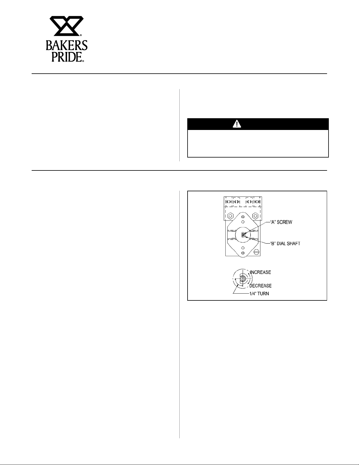
6. Remove control knob by grasping outer edge and
pulling straight out, without twisting or turning.
Figure 1
7. Hold thermostat dial shaft “B” (Figure 1) stationary
with pliers, and with a screwdriver, turn screw “A”
clockwise to obtain a lower temperature; or counterclockwise for higher temperature. Each 1/4 turn
(90° rotation) of screw “A” represents 18°F.
8. Replace thermostat control knob.
9. Recheck thermostat as in Steps 4 and 5 above. If
the fat temperature is not within 20 degrees of dial
setting (350°F +/- 20°F), it means that the sensing
element is inoperative and the thermostatic control
should be replaced.
4
Page 7
OPERATING
NOTICE
HEAVY DUTY ELECTRIC FRYER OPERATION MANUAL
Removing Fry Tanks
(Fry tanks equipped with drain are not to be removed):
1. Remove fry baskets.
2. Carefully grasp the element handle. CAUTION:
May be hot. Pull out the head lock on the left of
the head.
3. Lift the element handle while at the same time,
pulling the head lock. This will permit lifting the
elements to just above frying compound level in
tank. The element can be left in this position for
draining frying compound.
MAINTENANCE
Fill Fry Tank:
1. Fill the fry tank half way between the MAX and
MIN marks on the tank with approximately 15 lbs.
of liquid or melted frying compound. Do not fill
past the MAX.
4. Again, lift the element handle while pulling the
head lock, until the elements lock themselves at a
higher position.
5. Firmly grasp both handles of fry tank and lift it out.
After replacing the fry tank, simply pull the head
lock; and at the same time, pull down the element
handle until the elements rest on fry tank bottom.
6. Both the lifting out and lowering of elements can
be done in one swing, without stopping at the
intermediate position.
3. Use a quality frying compound.
4. Filter the frying compound frequently, at least once
a day.
5. Skim out food particles frequently with the
strainer/skimmer.
This fryer is not equipped with a melt cycle
option. Air holes caused when packing solid frying
compound into the fryer can cause hot spots on the
heating element sheath, resulting in momentary
overheating of some of the frying compound and
premature frying compound breakdown. It can also
damage the heating elements. If it is necessary
to use solid frying compound, it must be melted
before adding to fry tank.
Turn the thermostat to the desired frying
temperature. The yellow “HEAT ON” light will stay
on until the temperature set on the thermostat
is reached, then the light cycles off. The fryer is
now ready to begin frying. After a load has been
fried, do not lower the next load into the frying
compound until the “HEAT ON” light cycles off.
2. Do not let the frying compound level drop below
the MIN mark on the tank. For proper operation
of the fryer and good frying results, the frying
compound level should be maintained.
6. Add at least 15% (of fry tank capacity) of fresh
frying compound daily, (more if possible) without
overloading the tank. If 15% of the frying
compound is not used during frying, remove
some of the frying compound for other use (gravy,
griddle frying, etc.) to permit adding fresh frying
compound.
7. Do not overload the fry baskets. Approximately
half-full or less is correct. If foods are taking
longer to fry than the chart shows, or are not
browning, over-loading is a probable cause.
8. Prepare the food properly.
9. Keep salt out of the frying compound. Do not salt
foods with the basket above the kettle.
10. Assure a good thermostat operation.
11. Keep the fry tank and elements clean.
5
Page 8

CLEANING
CAUTION
HEAVY DUTY ELECTRIC FRYER OPERATION MANUAL
1. The frequency of cleaning should depend on the
load conditions. Set a definite cleaning schedule
corresponding to how hard the kettle is used.
Cleaning should be done at least once a week.
A. Turn the thermostat to “OFF” and allow unit to
cool down.
B. Lift the elements to drain position. Wire brush
or scrape elements to remove any solids
adhering to the elements.
C. Raise the elements. Lift out fry tank. Strain
the frying compound into a clean container.
D. Replace empty fry tank, lower elements to rest
inside the tank.
E. Add water to the “MAX” mark on tank.
F. Add any good grade of cleaner, following
cleaning instructions.
Use only non-abrasive cleaners. Abrasive cleaners
could scratch the finish of your unit, marring
it’s appearance and making it susceptible to
dirt accumulation. Do Not use steel wool, other
abrasive cleaners or cleaners/sanitizers containing
chlorine, iodine, ammonia or bromine chemicals
as these will deteriorate the stainless steel and
glass material and shorten the life of the unit.
L. Lift out the fry tank and drain. Repeat steps J
& K with fry tank.
M. Rinse the inside of the tank with 2 cups of
vinegar.
N. Rinse with clean water until the vinegar odor is
gone. The fry tank must be thoroughly rinsed,
since even a trace of cleaner left inside the
tank will ruin frying compound.
O. Dry thoroughly. Replace the tank and lower the
elements.
P. Shut the unit off and cover tank until ready for
further use.
Q. Thin films of oil subjected to frying
temperatures quickly form into a gummy
consistency. In order to avoid these gum
formations, keep all other surfaces of the unit
clean by polishing stainless steel surfaces
with a damp cloth. To remove discolorations or
oil film, a nonabrasive cleaner may be used.
G. Turn the thermostat to 250°F and let the
heating unit bring the solution to a boil.
H. Boil long enough to loosen or dissolve all
varnish or carbon deposits, approximately 30
minutes.
I. Turn the unit off and lift out the elements to
drain position.
J. If necessary, clean the thermostat bulbs using
a long-handled fiber or plastic brush and mild
soap solution.
K. Rinse with clean water to remove all cleaning
mixture.
6
Page 9

SPECIFICATIONS
HEAVY DUTY ELECTRIC FRYER OPERATION MANUAL
Dimensions & Electrical Information
Model A B C D Watts Volts Amps
BPHEF-15Si 12 17.553 30.000 13.5 5700 208 23.8
12 17.553 30.000 13.5 5700 230 21.4
12 17.553 30.000 13.5 5700 240 20.6
BPHEF-30Ti 24 17.553 30.000 13.5 11400 208 47.6
24 17.553 30.000 13.5 11400 230 42.9
24 17.553 30.000 13.5 11400 240 41.2
7
Page 10
HEAVY DUTY ELECTRIC FRYER OPERATION MANUAL
WARNING
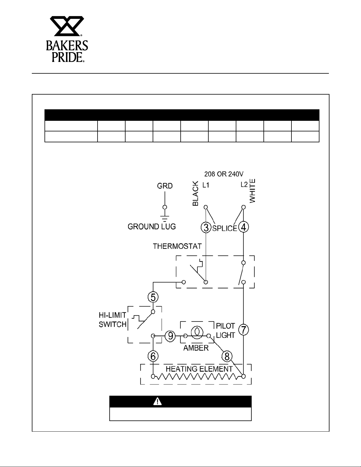
WIRING DIAGRAMS
CHECK DATA PLATE & CONNECT TO 208 OR 240V AS INDICATED.
MODEL # VOLTS WATTS AMPS WIRE VOLTS WATTS AMPS WIRE
BPHEF-15Si 240 5700 23.8 12 208 4280 20.6 12
BPHEF-15Si-208 - - - - 208 5700 27.5 10
Wire sizes listed above are for reference only. Check local codes or the National Electrical Code for
sizes to be used.
THIS UNIT TO BE CONNECTED TO 1Ø ONLY
8
Page 11

HEAVY DUTY ELECTRIC FRYER OPERATION MANUAL
WARNING
WIRING DIAGRAMS
CHECK DATA PLATE & CONNECT TO 208 OR 240V AS INDICATED.
MODEL # VOLTS WATTS AMPS WIRE VOLTS WATTS AMPS WIRE
BPHEF-30Ti 240 11400 47.6 6 208 8560 41.2 6
Wire sizes listed above are for reference only. Check local codes or the National Electrical Code for
sizes to be used.
THIS UNIT TO BE CONNECTED TO 1Ø ONLY
9
Page 12

HEAVY DUTY ELECTRIC FRYER OPERATION MANUAL
WARNING
WARNING
WIRING DIAGRAMS
CHECK DATA PLATE & CONNECT TO 208 OR 240V AS INDICATED.
MODEL # VOLTS WATTS AMPS WIRE VOLTS WATTS AMPS WIRE
BPHEF-30Ti 240 11400 23.8 & 23.8 12 208 8560 20.6 & 20.6 12
Wire sizes listed above are for reference only. Check local codes or the National Electrical Code for
sizes to be used.
THIS APPLIANCE HAS MORE THAN ONE POWER
SUPPLY CONNECTION POINT. DISCONNECT ALL
POWER SUPPLIES BEFORE SERVICING
THIS UNIT TO BE CONNECTED TO 1Ø ONLY
10
Page 13

HEAVY DUTY ELECTRIC FRYER OPERATION MANUAL
WARNING
WIRING DIAGRAMS
CHECK DATA PLATE & CONNECT TO 208 OR 240V AS INDICATED.
MODEL # VOLTS WATTS AMPS WIRE
BPHEF-30Ti-230 208 11400 55.0 4
Wire sizes listed above are for reference only. Check local codes or the National Electrical Code for
sizes to be used.
THIS UNIT TO BE CONNECTED TO 1Ø ONLY
11
Page 14

HEAVY DUTY ELECTRIC FRYER OPERATION MANUAL
TROUBLESHOOTING GUIDE
Possible Cause
Problem
Excessive and
premature foaming.
Greasy food/excessive
frying compound
absorption.
“Objectionable” odor
or flavor of frying
compound.
“Objectionable” flavor
of fried food.
Excessive smoking of
frying compound.
Excessive darkening of
frying compound.
Frying compound won’t
hold heat.
Food crust color not
brown.
Rapid breakdown of
frying compound.
Frying temperature too high/ overheating. (Check
thermostat)
Frying temperature too low. (Check thermostat)
Overloading the fry tank.
Improper draining of food after frying.
High moisture content in food being fried.
Inadequate frying compound turnover.
Improper preparation of food.
Contamination of frying compound. (Due to salt
or other foreign material)
Frying in foam.
Food being fried may be of poor quality.
Food being fried may be of poor quality.
Poor quality of frying compound (Either initially
or after excessive use)
Cooking time too short.
Inadequate filtering of frying compound.
Excessive crumbs in fry tank.
Keeping food in frying compound after cooking.
X X X X X X X
X X X X X X X X X
X X X X X X X X X
X X X X X X X X X
X X X X X X X
X X X X X X X
X X X X
X X X X X X
X X X X X X X X X
Inadequate cleaning of fry tank.
12
Page 15

HEAVY DUTY ELECTRIC FRYER OPERATION MANUAL
SUGGESTED TEMPERATURES AND TIMES
Food Control
Setting (°F)
DOUGHNUTS SEAFOOD
Cake Type 375° 1-1/2 - 2 Fish Cakes 350° 2 - 3
Yeast Raised 375° 2 - 2-1/2 Clams 350° 1 - 3
MEAT
Cutlets (Less than 1/2” thick) 350° 5 - 8 Oysters 350° 2 - 5
Chicken Fried Steak 350° 5 - 8 Scallops 350° 3 - 5
Chops (Very lean) 350° 5 - 8 Shrimp 350° 4 - 6
MISCELLANEOUS
Chinese Noodles 375° 1 - 2
Croquettes 350° 2 - 3 Egg Plant 350° 5 - 7
French Toast 350° 2 - 3 Onion Rings 350° 3 - 5
Glazed Cinnamon Apples 300° 5 - 10 Potatoes
French Fried Sandwiches 350° 1 - 2 (1/2" Strips, one-operation) 350° 6 - 9
POULTRY
Chicken (Large pieces) 325° 10 - 5 Potatoes (Brown) 350° 2 - 3
Chicken (Small pieces) 350° 7 - 10 Potatoes (Julienne) 350° 3 - 5
Chicken (Pre-cooked) 325° - 350° 3 - 5
Turkey (Small pieces) 325° 9 - 10
Time in
Minutes
Food Control
Setting (°F)
Fillets (Small) 350° 3 - 5
Smelts 350° 4 - 6
VEGETABLES
Potatoes (Blanch) 350° 4 - 6
Time in
Minutes
13
Page 16

HEAVY DUTY ELECTRIC FRYER OPERATION MANUAL
REPLACEMENT PARTS
Control Head (Models: BPHEF-15Si & BPHEF-30Ti)
Item P/N Description Quan Item P/N Description Quan
1 218100-95 Control Head, Elec. Fryer W/A 1 9 64285901 Clamp Bulb 4
2 1439729 Heating Unit Assembly 1 10 8944100 Clip Lead 4
3 13801-00 Switch, Hi-limit 1 11 8837018 Label Reset 1
4 81300-00 8-32 X 3/8 Type T 2 12 8108300 Screw, Pan Head 6-32 X 1/2 4
5 1515300 Ind Light,rect,amb,250v,2/tabs 1 13 8500600 Washer, Lock #6 SS 4
6 14876-00 Thermostat 1 14 8402900 Nut, Hex, 6-32 SS 4
7 8705504 Knob, Thermostat 1 15 8103400 Screw, Mach, 6-32 X 1/4" Lg. 2
8 2125502 Grommet Split 2 16 8455700 Nut, PAL 5/8-18 2
14
Page 17

REPLACEMENT PARTS
BPHEF-15Si
HEAVY DUTY ELECTRIC FRYER OPERATION MANUAL
Item P/N Description Qty Item P/N Description Qty
1 21828325 Body, Fryer BP 1 18 8422400 #10-24 Hx Nut Grn
2 21810065 Support, Head Weld Assembly LS 1 19 8158800 MS Rd Hd Ph 10-24 X 1/2
3 21810075 Head Support Outside Weld Assy 1 20 5161000 Connector Cable Romex
4 8415500 Head Support Inside 1 21 21828318 Panel, Front
5 89670-00 Wing Nut 10-32 S/S 4 22 21828038 Fabble, Interior
6 89670-00 Bushing, Snap Heyco .5” I.D. 1 23 21810040 Door Electric Fryer
7 21810010 Fat Container AY 1 24 8808900 Nameplate, Backers Pride 8”
8 3101230 Basket, 1/2 Size 2 25 43813103 Label, Wrng, Hot Surfc
9 21828240 Control Ay, 208/240ºf 1 26 43813149 Label, Wrn Hot Surf (Frnch)
10 21810096 Cover Head 1 27 21810018 Label, Diagram
11 8170700 Screw, 10-32X1/2, Type AB 37 28 8861000 Label, Spec
12 2180023 Bracket Handle 1 29 8824200 Label, Button Position
13 2180022 Element Handle 1 30 64416801 Label, 90 Deg C
14 8141400 8-32 X 1/2 MS 2 31 2901051 Carton Rsc 39.25X19.87x20.18
15 84101-00 Nut, Hex 8/32 S/S 2 32 81357-00 Screw, 8-32 X 3/8” Ft Hd
16 22495100 Back Bottom W/A 1 33 8408300 #8-32 Hex Nut, KEPS, NI
17 8633700 Leg, Heavy Duty 2” Dia, W/ Foot Flange 4 34 8825300 Decal, Leg
15
Page 18

REPLACEMENT PARTS
BPHEF-30Ti
HEAVY DUTY ELECTRIC FRYER OPERATION MANUAL
Item P/N Description Qty Item P/N Description Qty
1 21828526 Weldment, Body BPHEF-30TI 1 18 8422400 #10-24 Hx Nut Grn 1
2 21810065 Support, Head Weld Assembly Ls 1 19 8158800 MS Rd Hd Ph 10-24 X 1/2 1
3 21810265 Support, Head Weld Assembly Rs 1 20 5161000 Connector Cable Romex 1
4 21810275 Head Suppor, Outside Assy. 1 21 21828518 Panel, Front 1
5 21810285 Head Support, Inside Assy. 1 22 31012-32 Basket, Full Size, 30H 2
6 8415500 Wing Nut 10-32 SS 6 23 21828038 Baffle, Interior 2
7 89785-00 Bushing, 1" Snap, Heyco 1 24 21810040 Door Electric Fryer 1
8 21810010 Fat Container AY 2 25 8808900 Nameplate, BAKERS PRIDE
9 21828240 Control Ay. 208/240 °F 2 26 43813103 Label, Wrng, Hot Surfc 2
10 21810096 Cover Head 2 27 43813149 Label, Wrn Hot Surf (Frnch) 2
11 8170700 Screw, 10-32X1/2, Type AB 51 28 21810218 Label, Diagram El. Twin Fryer 208/240V Units 1
12 21810023 Bracket Handle 2 29 8861000 Label, Spec 1
13 21810022 Element Handle 2 30 8824200 Label, Button Position 2
14 8141400 8-32 X 1/2 MS 4 31 64416801 Label, 90 Deg C 1
15 84104-00 Nut,Hex, 8-32 SS 4 32* 29087-42 Skid, 44 X 32 For 42" Merchandiser 1
16 21828134 Back And Bottom Weldment W/O Drain 1 33* 29088-42 Carton, Hsc 43.25 X 30.25 X 33.25 275 Dw 1
17 8633700 Leg, Heavy Duty 2" Dia. W/ Foot Flange 4 34 81357-00 Screw, 8-32 X 3/8" Ft Hd 2
8” 1
16
Page 19

REPLACEMENT PARTS
BPHEF-15Si (CE)
HEAVY DUTY ELECTRIC FRYER OPERATION MANUAL
Item P/N Description Qty Item P/N Description Qty
1 21828325 Body, Fryer BP 1 21 8158800 MS Rd Hd Ph 10-24 X 1/2 1
2 21810065 Support, Head Weld Assembly LS 1 22 5161000 Connector Cable Romex 1
3 21810075 Head Support Outside Weld Assy 1 23 21828319 Panel, Front 1
4 21810085 Head Support Inside 1 24 21828038 Baffle, Interior 1
5 8415500 Wing Nut 10-32 S/S 4 25 1302100 Relay, Solid State 1
6 89670-00 Bushing, Snap Heyco .5" I.D. 1 26 21810042 Capacitor, Assy 1
7 21810010 Fat Container AY 1 27 8103400 Screw, Mach, 6-32 X 1/4" Lg. 2
8 3101230 Basket, 1/2 Size 2 28 21810040 Door Electric Fryer 1
9 21810150 Control Ay. 208/240 °C 1 29 8808900 Nameplate, BAKERS PRIDE
10 21810096 Cover Head 1 30 1305612 Switch, Rocker 20 Amp 1
11 8170700 Screw, 10-32X1/2, Type Ab 37 31 43813103 Label, Wrng, Hot Surfc 1
12 21810023 Bracket Handle 1 32 43813149 Label, Wrn Hot Surf (Frnch) 1
13 21810022 Element Handle 1 33 21810017 Label, Diagram El. 15Lb Ce Units 1
14 8141400 8-32 X 1/2 MS 4 34 8861000 Label, Spec 1
15 84104-00 Nut,Hex, 8-32 SS 4 35 8824200 Label, Button Position 1
16 22495100 Back, Bottom W/A 1 36 64416801 Label, 90 Deg C 1
17 8633700 Leg, Heavy Duty 2" Dia. W/ Foot Flange 4 37* 2901051 Carton, Rsc 39.25X19.87x20.18 1
18 11141-00 Lug, Solderless 1 38 81357-00 Screw, 8-32 X 3/8" Ft Hd 2
19 8422400 #10-24 Hx Nut Grn 1 39 8408300 #8-32 Hex Nut, KEPS, NI 2
20 88370-01 Label, Ground Marker 1 40 8825300 Decal, Leg 1
8” 1
17
Page 20

REPLACEMENT PARTS
BPHEF-30Ti (CE)
HEAVY DUTY ELECTRIC FRYER OPERATION MANUAL
Item P/N Description Qty Item P/N Description Qty
1 21828526 Weldment, Body
2 21810065 Support, Head Weld Assembly LS 1 23 21828519 Panel, Front 1
3 21810265 Support, Head Weld Assembly RS 1 24 31012-32 Basket, Full Size, 30H 2
4 21810275 Head Suppor, Outside Assy. 1 25 21828038 Baffle, Interior 2
5 21810285 Head Support, Inside Assy. 1 26 1302100 Relay, Solid State 2
6 8415500 Wing Nut 10-32 S/S 6 27 21810042 Capacitor, Assy 2
7 89785-00 Bushing, 1" Snap, Heyco 1 28 8103400 Screw, Mach, 6-32 X 1/4" Lg. 4
8 21810010 Fat Container AY 2 29 21810040 Door Electric Fryer 1
9 21810150 Control AY. 208/240 °C 2 30 8808900 Nameplate, BAKERS PRIDE
10 21810096 Cover Head 2 31 1305612 Switch, Rocker 20 Amp 2
11 8170700 Screw, 10-32X1/2, Type AB 51 32 43813103 Label, Wrng, Hot Surfc 2
12 21810023 Bracket Handle 2 33 43813149 Label, Wrn Hot Surf (Frnch) 2
13 21810022 Element Handle 2 34 21810216 Label, Diagram El. Twin Fryer Ce Units 1
14 8141400 8-32 X 1/2 Ms 8 35 8861000 Label, Spec 1
15 84104-00 Nut,Hex, 8-32 S/S 8 36 8824200 Label, Button Position 2
16 21828135 Back And Bottom Weldment W/O Drain 1 37 64416801 Label, 90 Deg C 1
17 8633700 Leg, Heavy Duty 2" Dia. W/ Foot Flange 4 38* 29087-42 Skid, 44 X 32 For 42" Merchandiser 1
18 11141-00 Lug, Solderless 1 39* 29088-42 Carton, Hsc 43.25 X 30.25 X 33.25 275 DW 1
19 8422400 #10-24 Hx Nut Grn 1 40 81357-00 Screw, 8-32 X 3/8" Ft Hd 2
20 88370-01 Label, Ground Marker 1 41 8408300 #8-32 Hex Nut, KEPS, NI 2
21 8158800 MS Rd Hd Ph 10-24 X 1/2 1 42 8825300 Decal, Leg 1
Hdef
-30Bl 1 22 5161000 Connector Cable Romex 1
8” 1
18
Page 21

CONVEYOR OVEN SERVICE MANUAL
BAKERS PRIDE LIMITED WARRANTY
WHAT IS COVERED This warranty covers defects in material and workmanship under normal use, and applies only to the original purchaser
• The equipment has not been accidentally or intentionally damaged, altered or misused;
• The equipment is properly installed, adjusted, operated and maintained in accordance with National
• The serial number rating plate affixed to the equipment has not been defaced or removed.
WHO IS COVERED This warranty is extended to the original purchaser and applies only to equipment purchased for use in the U.S.A.
COVERAGE PERIOD Cyclone Convection Ovens: BCO Models: One (1) Year limited parts and labor; (1) Year limited door warranty.
GDCO Models: Two (2) Year limited parts and labor; (2) Year limited door warranty.
CO11 Models: Two (2) Year limited parts and labor; (5) Year limited door warranty.
All Other Products: One (1) Year limited parts and labor. Warranty period begins the date of dealer invoice to customer
WARRANTY This warranty covers on-site labor, parts and reasonable travel time and travel expenses of the authorized service
COVERAGE Representative up to (100) miles, round trip, and (2) hours travel time. The purchaser, however, shall be responsible for
EXCEPTIONS All removable parts in Bakers Pride
providing that:
and local codes and in accordance with the installation instruction provided with the product;
or ninety (90) days after shipment date from Bakers Pride - whichever comes first.
all expenses related to travel, including time, mileage and shipping expenses on smaller counter models that may be
carried into a Factory Authorized Service Center, including the following models: PX-14, PX-16, P18, P22S, P24S, PD-4,
PDC, WS Series and BK-18.
®
and Valves, are covered for a period of SIX MONTHS. All Ceramic Baking Decks are covered for a period of THREE
MONTHS. The installation of these replacement decks is the responsibility of the purchaser. The extended Cyclone door
warranty years 3 through 5 is a parts only warranty and does not include labor, travel, mileage or any other charges.
cooking equipment, including but not limited to: Burners, Grates, Radiants, Stones
EXCLUSIONS
INSTALLATION Leveling and installation of decks as well as proper installation and check out of all new equipment —per appropriate
REPLACEMENT PARTS Bakers Pride genuine Factory OEM parts receive a (90) day materials warranty effective from the date of installation by a
This Warranty is in lieu of all other warranties, expressed or implied, and all other obligations or liabilities on the manufacturer’s part. Bakers Pride
shall in no event be liable for any special, indirect or consequential damages, or in any event for damages in excess of the purchase price of the unit.
The repair or replacement of proven defective parts shall constitute a fulfillment of all obligations under the terms of this warranty.
• Negligence or acts of God,
• Failures caused by erratic voltages or gas supplies,
• Thermostat calibrations after (30) days from
equipment installation date,
• Unauthorized repair by anyone other than a Bakers
Pride Factory Authorized Service Center,
• Air and Gas adjustments,
• Damage in shipment,
• Light bulbs,
• Alteration, misuse or improper installation,
• Glass doors and door adjustments,
installation and use materials — is the responsibility of the dealer or installer, not the manufacturer.
Bakers Pride Factory Authorized Service Center.
• Thermostats and safety valves with broken capillary
tubes,
• Fuses,
• Char-broiler work decks and cutting boards,
• Tightening of conveyor chains,
• Adjustments to burner flames and cleaning of pilot
burners,
• Tightening of screws or fasteners,
• Accessories — spatulas, forks, steak turners, grate
lifters, oven brushes, scrapers, peels. etc.,
• Freight — other than normal UPS charges,
• Ordinary wear and tear.
Form #U4177A 1/07
19
Page 22

Food Service Equipment Group
The Standex Food Service Equipment Group (FSEG) is a manufacturer of innovative commercial food
service equipment offering a wealth of refrigeration and cooking expertise. Products include walk-in
coolers and freezers; hot and cold display cabinets, cases, and storage systems; commercial ovens,
rotisseries, and cooking equipment; and rotary vane pumps.
Ask your sales representative about how the power of all Standex brands can work for you.
www.standex.com/segments/food-service
Be sure to keep up with new product announcements
and events on social media!
 Loading...