

Page 1
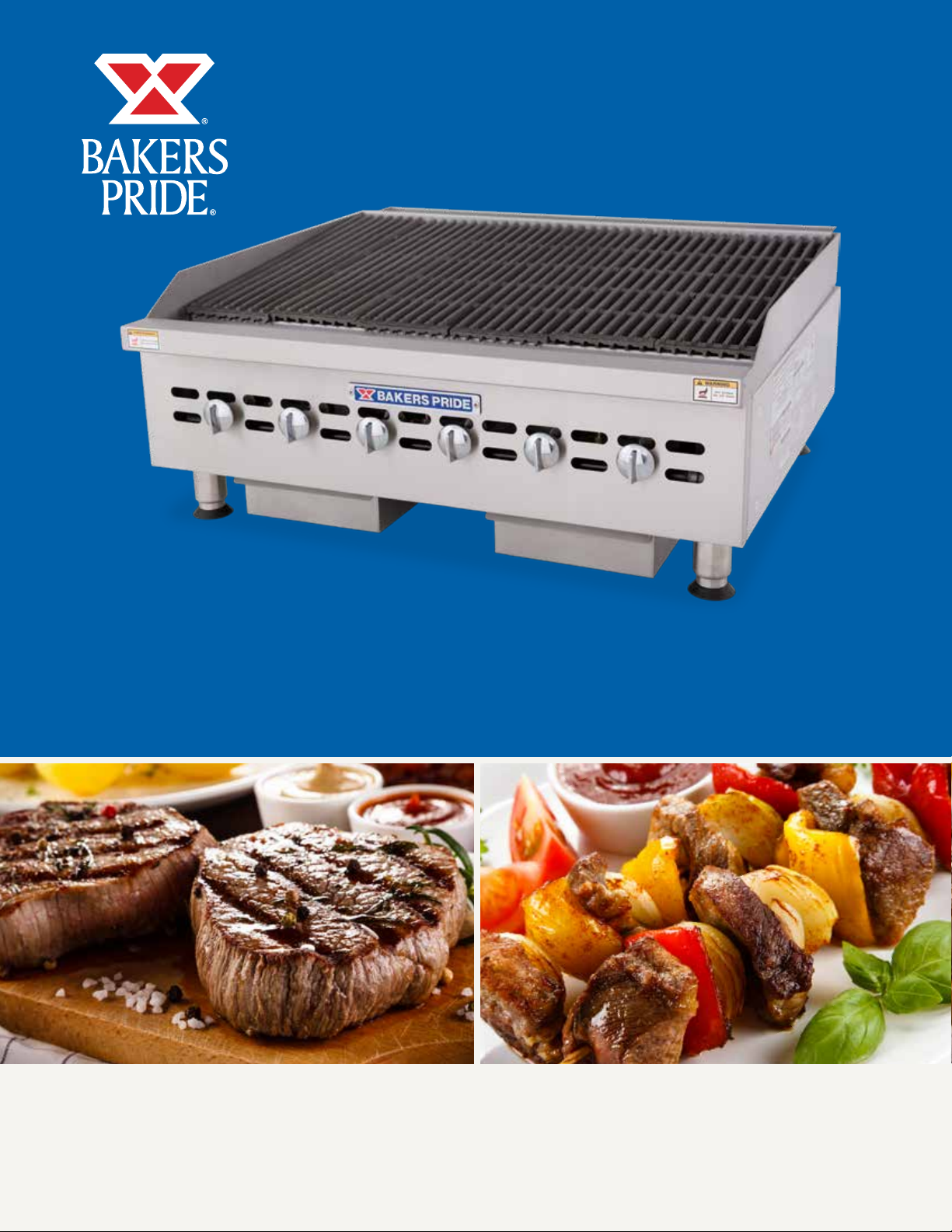
OPERATION MANUAL
HD COOKLINE SERIES COUNTERTOP CHARBROILERS
SERIES: BPHCB & BPHCRB
BUILT BY CRAFTSMEN. TESTED BY TIME®.
Page 2
HEAVY DUTY GAS CHARBROILER OPERATION MANUAL
HEAVY DUTY GAS CHARBROILER OPERATION MANUAL
Heavy Duty Gas CharBroiler Models:
BPHDCB-2424i, BPHDCB-2436i, BPHDCB-2448i, BPHD-
CB-2460i, BPHDCB-2472i
Heavy Duty Charrock Gas Broiler Models:
BPHDCRB-2424i, BPHDCRB-2436i, BPHDCRB-2448i,
BPHDCRB-2460i, BPHDCRB-2472i
Bakers Pride Oven Company, LLC is a wholly owned
subsidiary of Standex International Corporation.
All gas operated Bakers Pride® charbroilers are intended
for use with the type of gas specified on the rating plate
and for installation will be in accordance with National
Fuel Gas Code ANSI Z223.1 (latest edition)
WARNING
FOR YOUR SAFETY: Do not store or use gasoline
or other flammable vapors or liquids in the vicinity
of this or any other appliance.
WARNING
Improper installation, adjustment, alteration,
service or maintenance can cause property
damage, injury or death. Read the installation,
operating and maintenance instructions
thoroughly before installing or servicing this
equipment.
WARNING
Instructions must be posted in a prominent
location. All safety precautions must be taken in
the event the user smells gas. Safety information
can be obtained from your local gas supplier.
Please retain this manual for future references.
This equipment is design engineered for commercial
use only.
WARNING
California Residents Only
WARNING: This product can expose you to
chemicals including chromium which is known to
the State of California to cause cancer and birth
defects or other reproductive harm. For more
information go to www.P65Warnings.ca.gov.
BAKERS PRIDE OVEN COMPANY, LLC.
1307 N. Watters Rd., Suite 180
Allen, TX 75013
Phone: 800.527.2100 | Fax: 914.576.0605 | www.bakerspride.com
P/N 8822411 9/18
Page 3
HEAVY DUTY GAS CHARBROILER OPERATION MANUAL
CAUTION
WARNING
WARNING
NOTICE
WARNING
TABLE OF CONTENTS
INTRODUCTION 1
SAFETY PRECAUTIONS 2
GENERAL INSTALLATION INSTRUCTIONS 3
SPECIFICATIONS & DIMENSIONS 4
CONVERSION 7
LIGHTING INSTRUCTIONS 8
OPERATING INSTRUCTIONS 10
CLEANING/MAINTENANCE 11
SERVICE/REPAIR 12
TROUBLESHOOTING GUIDE 12
REPLACEMENT PARTS LISTS & EXPLODED VIEWS 13
WARRANTY 20
INTRODUCTION
These models are designed, built, and sold for
commercial use. If these models are positioned
so the general public can use the equipment,
make sure that cautions, warnings, and operating
instructions are clearly posted near each unit so that
anyone using the equipment will use it correctly and
not injure themselves or harm the equipment.
Improper installation, adjustment, alteration,
service or maintenance can cause property
damage, injury or death. Read the installation,
operating and maintenance instructions thoroughly
before installing or servicing this equipment.
Instructions to be followed if anyone smells gas
should be posted in a prominent place. These may
be obtained from the gas supplier.
GAS PRESSURE
The appliance and it’s individual shutoff valve (to be
supplied by user) must be disconnected from the gas
supply piping system during any pressure testing of that
system at test pressures in excess of 1/2 psi (3.45 kPa).
NOTE: Gas shutoff valve is supplied on CE models.
The appliance must be isolated from the gas supply
piping system by closing it’s individual manual shutoff valve during any pressure testing of the gas supply
piping system at test pressures equal to or less than
1/2 psi (3.45 kPa).
For your safety do not store or use gasoline or
other flammable vapors and liquids in the vicinity
of this or any other appliance. Keep the area free
and clear of combustibles. (See ANZI Z83. 14B,
1991).
A factory authorized agent should handle all
maintenance and repair. Before doing any
maintenance or repair, contact Bakers Pride.
1
Page 4
INTRODUCTION
DANGER
WARNING
CAUTION
NOTICE
NOTICE
CAUTION
HEAVY DUTY GAS CHARBROILER OPERATION MANUAL
Bakers Pride takes pride in the design and quality of our
products. When used as intended and with proper care
and maintenance, you will experience years of reliable
operation from this equipment. To ensure best results, it
is important that you read and follow the instructions in
this manual carefully.
Location Of Data Plate
The data plate is located on the right side panel
Immediately Inspect For Shipping Damage
All containers should be examined for damage
before and during unloading. The freight carrier has
assumed responsibility for its safe transit and delivery.
If equipment is received damaged, either apparent or
concealed, a claim must be made with the delivering
carrier.
A) Apparent damage or loss must be noted on the
freight bill at the time of delivery. It must then be
SAFETY PRECAUTIONS
signed by the carrier representative (Driver). If this
is not done, the carrier may refuse the claim. The
carrier can supply the necessary forms.
B) Concealed damage or loss if not apparent until
after equipment is uncrated, a request for
inspection must be made to the carrier within 15
days. The carrier should arrange an inspection. Be
certain to hold all contents and packaging material.
Installation and start-up should be performed by a
qualified installer who thoroughly read, understands and
follows these instruction.
If you have questions concerning the installation,
operation, maintenance or service of this product,
write Technical Service Department Bakers Pride Oven
Company, Inc., 30 Pine Street, New Rochelle, NY,
10801.
This symbol warns of imminent hazard which will
result in serious injury or death.
This symbol refers to a potential hazard or unsafe
practice, which could result in serious injury or
death.
This symbol refers to a potential hazard or unsafe
practice, which may result in or moderate injury or
product or property damage.
This symbol refers to information that needs
special attention or must be fully understood even
though not dangerous.
This product is intended for commercial use only.
Not for household use.
These models are designed, built, and sold for
commercial use. If these models are positioned
so the general public can use the equipment
make sure that cautions, warnings, and operating
instructions are clearly posted near each unit
so that anyone using the equipment will use it
correctly and not injure themselves or harm the
equipment.
2
Page 5
SAFETY PRECAUTIONS
WARNING
NOTICE
CAUTION
HEAVY DUTY GAS CHARBROILER OPERATION MANUAL
Improper installation, operation, service or
maintenance can cause property damage, injury
or death. Read and understand these instructions
thoroughly before positioning, installing,
maintaining or servicing this equipment
GENERAL INSTALLATION INSTRUCTIONS
Ensure gas supply and gas type, as shown on unit
nameplate agree.
Unit installation must conform with the National
Fuel Gas Code, ANSI Z223.1/NFPA 54, the National
Gas Installation Code, CSA-B149.1, or the Propane
Installation Code, CSA-B149.2 as applicable and in
accordance with local codes.
Screw legs into the permanently fastened nuts on the
four corners of the unit and tighten by hand. Level the
unit by turning the adjustment screw at the bottom
of each leg. Do not slide unit with legs mounted, lift if
necessary to move unit.
Pipe threading compound must be resistant to the action
of liquefied petroleum gases.
DO NOT use an open flame to check for leaks.
Check all gas piping for leaks with a soap and
water solution before operating unit.
THESE UNITS ARE SUITABLE FOR INSTALLATION ON
NON-COMBUSTIBLE SURFACES ONLY.
Local codes regarding installation vary greatly from
one area to another. The National Fire Protection
Association, Inc., states in its NFPA96 latest
edition that local codes are “Authority Having
Jurisdiction” when it comes to requirement for
installation of equipment. Therefore, installation
should comply with all local codes.
Do not obstruct the flow of combustion and ventilation
air, under the unit by the legs or behind the unit by the
flue.
Adequate clearance for air openings into the combustion
chamber is required. Do not place objects between the
bottom of the unit and the counter top.
There must be adequate clearance for removal of the
front panel. All major parts except the burners are
removable thru the front if the gas line is disconnected.
Unit must have adequate clearances for servicing.
(Sides = 0”, Rear = 0”, Floor = 4”).
European Community Installation Instructions:
“THIS APPLIANCE MUST BE FITTED BY A
COMPETENT PERSON. IN THE UK, CORGI
REGISTERED INSTALLERS (INCLUDING THE REGIONS
OF BRITISH GAS) UNDERTAKE TO WORK TO SAFE
AND SATISFACTORY STANDARDS. THIS APPLIANCE
MUST BE INSTALLED IN ACCORDANCE WITH THE
GAS SAFETY (INSTALLATION AND USE) REGULATIONS
AND THE RELEVANT BUILDING REGULATIONS / IEE.
REGULATIONS. DETAILED RECOMMENDATIONS ARE
CONTAINED IN THE FOLLOWING BRITISH STANDARD
CODES OF PRACTICE - BS 6172, BS 5440 PART 2, BS
6891”
Noncombustible clearances:
0” sides (0 mm) 0” rear (0 mm) 4” floor (102mm)
“THIS APPLIANCE MUST BE INSTALLED IN
ACCORDANCE WITH THE RULES IN FORCE”
“MUST BE INSTALLED IN A WELL VENTILATED AREA.
Ventilation requirements ie. B.S. 5440.”
3
Page 6
HEAVY DUTY GAS CHARBROILER OPERATION MANUAL
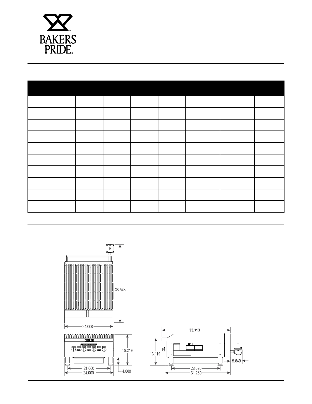
SPECIFICATIONS AND DIMENSIONS
Model Width
In. (mm)
BPHDCB-2424i 24"
(609.6)
BPHDCB-2436i 36”
(914.4)
BPHDCB-2448i 48”
(1219.2)
BPHDCB-2460i 60”
(1524.0)
BPHDCB-2472i 72”
(1828.8)
BPHDCRB-2424i 24”
(609.6)
BPHDCRB-2436i 36”
(914.4)
BPHDCRB-2448i 48”
(1219.2)
BPHDCRB-2460i 60”
(1524.0)
BPHDCRB-2472i 72”
(1828.8)
Depth
In. (mm)
33.312"
(846)
33.312”
(846)
33.312”
(846)
33.312”
(846)
33.312”
(846)
33.312”
(846)
33.312”
(846)
33.312”
(846)
33.312”
(846)
33.312”
(846)
Height
In. (mm)
15.217"
(386.5)
15.217"
(386.5)
15.217"
(386.5)
15.217"
(386.5)
15.217"
(386.5)
15.217"
(386.5)
15.217"
(386.5)
15.217"
(386.5)
15.217"
(386.5)
15.217"
(386.5)
Number of
Burners
4 20,000
6 20,000
8 20,000
10 20,000
12 20,000
4 20,000
6 20,000
8 20,000
10 20,000
12 20,000
BPHDCB & BPHDCRB-2424i, 24” GAS CHARBROILER
Btu/kw Burner
Natural Gas
(5.86)
(5.86)
(5.86)
(5.86)
(5.86)
(5.86)
(5.86)
(5.86)
(5.86)
(5.86)
Total
Btu/kw Hour
80,000 (23.4) 5
120,000 (35.2) 5
160,000 (46.9) 5
200,000 (58.6) 5
240,000 (70.3) 5
80,000 (23.4) 5
120,000 (35.2) 5
160,000 (46.9) 5
200,000 (58.6) 5
240,000 (70.3) 5
W.C
In. (‘Mbar’)
(12.4)
(12.4)
(12.4)
(12.4)
(12.4)
(12.4)
(12.4)
(12.4)
(12.4)
(12.4)
21829500
4
Page 7

HEAVY DUTY GAS CHARBROILER OPERATION MANUAL
BPHDCB & BPHDCRB-2436i, 36” GAS CHARBROILER
21829600
BPHDCB & BPHDCRB-2448i, 48” GAS CHARBROILER
21829700
5
Page 8
HEAVY DUTY GAS CHARBROILER OPERATION MANUAL
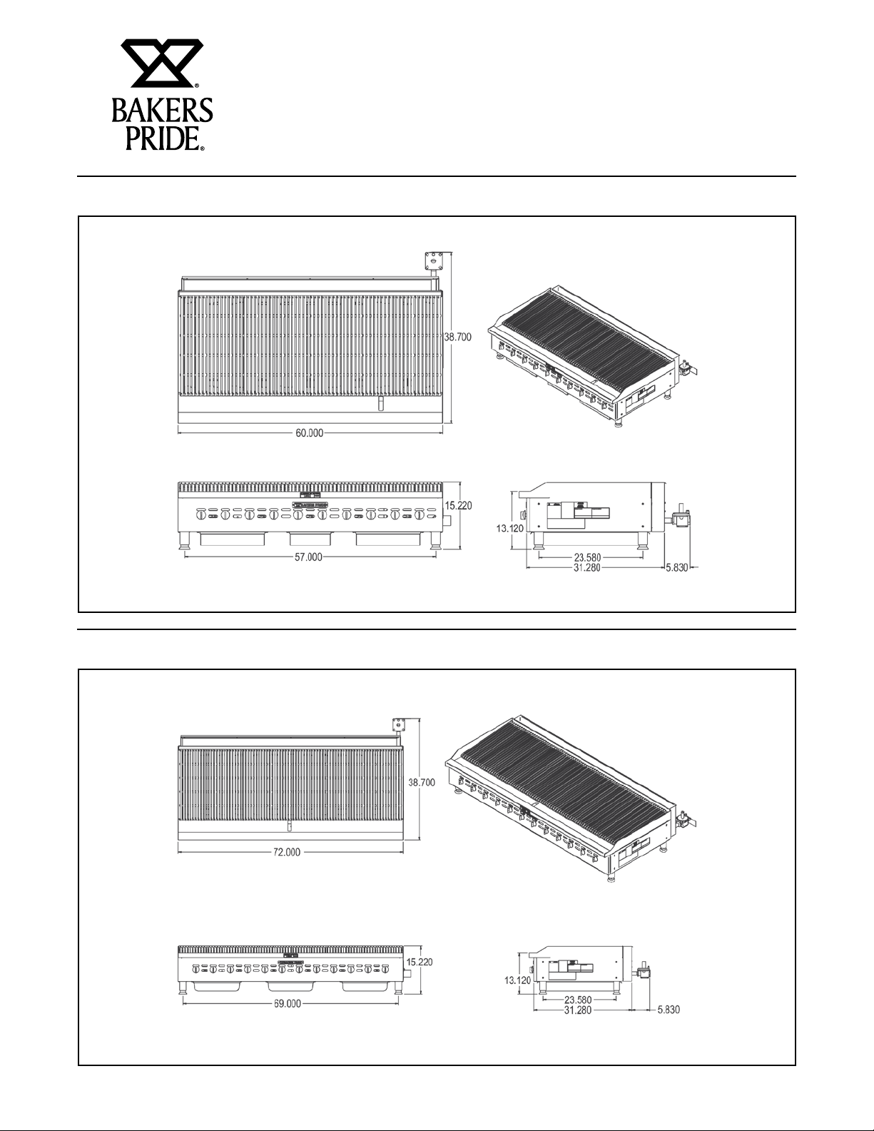
BPHDCB & BPHDCRB-2460i, 60” GAS CHARBROILER
21829800
BPHDCB & BPHDCRB-2472i, 72” GAS CHARBROILER
21829900
6
Page 9

HEAVY DUTY GAS CHARBROILER OPERATION MANUAL
WARNING
CONVERSION
• Instructions are for conversion from Natural Gas to
Propane (L.P.) on all models HDCRB & HDCB.
• The conversion should be done before connecting
the unit to the gas supply.
• Units are shipped from the factory equipped for use
on natural gas. Orifices necessary for L.P. (propane)
are provided in a bag tied to the valve on the front
panel.
1. Remove the knobs and front panel.
2. Remove the orifice fittings from the valve. Change
the orifices to the size recommended for propane
(L.P.).
3. Replace the orifice fittings into the valve.
• To change the regulator:
• Connect the regulator to the unit, connect gas and
check for leaks.
Do not use an open flame to check for leaks.
• Check the system
pressure. With the
front panel removed,
remove the plug from
the manifold.
• Place a fitting in the
plug opening and
connect a manometer.
• For Natural gas the pressure in the manifold should
be 5” water column or 12.4 millibar. For L.P. the
pressure in the manifold should be 10” water
Column of 24.9 millibar.
7
Page 10

HEAVY DUTY GAS CHARBROILER OPERATION MANUAL
NOTICE
CONVERSION
• To adjust the pressure remove the brass cap and
turn the white plastic part inside the stem of the
regulator. See picture regulator 8.
• Take a wide straight screw driver and place it in
the two notches shown in picture regulator 7 turn
clockwise to increase pressure and counter-clockwise
to reduce pressure. See picture regulator 8.
• Once the pressure has been adjusted replace the
brass cap.
LIGHTING INSTRUCTIONS
Note the blue cap on the regulator. This is the
vent. There are openings below the top rim.
NEVER block these openings your regulator will
fail to operate correctly. On at least a monthly
basis blow off any dust or grease which may
accumulate around this cap. The openings must
remain open for the regulator to function. Clean
more often in a very greasy atmosphere.
HDCB and HDCRB Broilers are furnished with either a
pilot safety valve or a standing pilot (not available in the
European Community). Please follow the instructions for
your unit.
Pilot Operation Flame Failure Gas Valve:
Operation of the gas valve pilot:
1. Turn knob on the main gas valve to the pilot
position
2. Depress knob to start gas flow to the pilot valve
3. Light pilot valve
a. Using a match or taper
4. Hold in knob for 15 to 30 seconds to heat up the
thermocouple
5. Release knob and turn to the desired gas flow
position
a. If pilot goes out repeat steps 1-4, some
thermocouples will take longer to heat up
Standing Pilot Lighting Instructions:
(Not Available in the European Community)
The pilot lights on the broilers have been set at the
factory. A screwdriver may be required for the first
lighting to adjust the flame for your elevation.
3. The valve can be accessed through an opening in
the front panel or remove the cooking grates and
light the pilot from above.
4. Turn the manual shut off valve on.
5. Hold an ignition source (match) to both openings
on the pilot tube. When the flames are established,
remove the ignition source.
6. Turn the burner knobs to “HI”. If the burner does
not ignite, promptly open the pilot valve more. If
the pilot flame appears larger than necessary, turn
it down and reset burner ignition. The pilot flame
should be as small as possible but large enough to
guarantee reliable ignition of the burners when the
knobs are turned to “HI”.
Relighting Pilot
If the pilot light should go out for any reason:
• Promptly shut off all gas at the manual shut off
valve.
• Turn off all knobs and pilot valves; wait 5 minutes to
clear gas.
• Relight following steps 4 through 6 under Standing
Pilot Lighting Instructions.
1. Turn off the manual shut off valve and wait 5
minutes to clear the gas.
2. Turn all knobs to the “OFF” position.
8
Page 11

HEAVY DUTY GAS CHARBROILER OPERATION MANUAL
CAUTION
LIGHTING INSTRUCTIONS
Lighting Main Burner:
Since the burner is lit from constantly burning pilot, turn
knobs to “HI” to put the unit in operation; then adjust to
any desired position between “LO” and “HI”.
• To light burner, turn knob to “MAX” then back off to
the desired flame level. The range of adjustment is
virtually infinite between high and off. (At the small
flame, there is a pre-set low).
• When the broiler is first heated, it will smoke until
oil used in manufacturing, preservation and dust
from storage and shipping are burned off. An hour at
“MAX” on all burners is usually sufficient.
• Turn knobs off and let cool.
• For first cooking, set the grates at maximum tilt
position and preheat before broiling. You will have to
experiment with knob settings and grate position for
each particular item.
• Keep the grease/water pan with sufficient water to
cover the entire bottom.
• Clean regularly. Grates may be removed for washing
in the sink. Brush out carbonized particles.
Thoroughly wash the grease/water pan.
European Community:
If adjustment becomes necessary in the field, it should be
done by a factory authorized and trained technician who
should seal the screw after the adjustment to safeguard
against un-authorized tampering by the end user.
All burners are lit from constantly burning pilots. Turning
the valve to the desired flame height is all that is required
to put the unit in service.
Do not permit fans to blow directly at the unit. Wherever
possible, avoid open windows next to the units’ sides
or back. Avoid wall type fans which create air crosscurrents within a room.
It is also necessary that sufficient air should be allowed
to enter the room to compensate for the amount of
air removed by any ventilating system. Otherwise, a
subnormal atmospheric pressure will occur, affecting
operation and causing undesirable working conditions.
A properly designed and installed hood will act as the
heart of the ventilating system for the room or area
in which the unit is installed, and will leave the unit
independent of changing draft conditions.
All valves must be checked and lubricated periodically.
This must be done by an authorized service
representative in your area.
Never attempt to move a grill section while cooking.
An unexpected flare could cause severe injury. Turn
off the unit, let it cool and use potholders and/or
gloves to reposition or remove. The space between
the legs at the bottom admits combustion air. DO
NOT BLOCK THIS SPACE.
Main burner air supply:
For efficient burner operation, a proper balance of gas
volume and primary air supply must be maintained
which will result in complete combustion. Insufficient air
supply results in a yellow streaming flame. Primary air
supply is controlled by an air shutter on the front of the
burner.
Loosen the screws on the front of the burner, and adjust
the air shutter to just eliminate the yellow tips of the
burner flame. Lock the air shutter in place by tightening
the screws.
9
Page 12

HEAVY DUTY GAS CHARBROILER OPERATION MANUAL
NOTICE
CAUTION
OPERATING INSTRUCTIONS
Operation
Turn the burners on about 15-20 minutes before
cooking for preheating. Set the knobs to the desired
flame height or temperature. Each valve will control
the gas flow to the burner to bring that area of the unit
up to the set temperature. If different temperature
settings are to be used, adjoining areas should be set
at progressively higher temperatures using the lowest
temperatures on the outside burners. A uniform and
systematic approach to the loading of the unit will
produce the most consistent product results.
Radiants
Place the radiants in their position as shown in Sketch
1. Make sure that the radiants are setting properly
into the slots on the front and rear supports. Radiants
should be centered over straight section of the burners.
Do not turn on gas valves without lighting the
pilots. This could cause a build up of gas and
potential explosion.
Cooking Grates
Place the top cooking grates with the grid bars sloping
toward the front as shown in Sketch 2.
Season Griddle
Heat to low temperature (300 - 350 F/150-180C)
and pour on a small amount of cooking oil, about one
ounce (30cc) per square foot of surface. Spread the oil
over the entire griddle surface with a cloth to create a
thin film. Wipe off any excess oil with a cloth. Repeat
this procedure 2 to 3 times until the griddle has a
slick, mirror-like surface.
When cooking grates are placed sloping toward
the front, the grooves on top will guide the excess
fat drippings into the grease trough. For wider
branding marks turn the cooking grate over so the
product is placed on the wider rails. There is less
grease removal with the cooking grates in this
position so there will be a little more flare ups in
this position.
Sketch 1
Sketch 2
10
Page 13

HEAVY DUTY GAS CHARBROILER OPERATION MANUAL
NOTICE
CAUTION
NOTICE
CLEANING / MAINTENANCE
Initial Cleaning:
Prior to operating your new broiler, thoroughly wash
the exterior with a mild detergent or soap solution. Do
not use abrasive cleaners, since this might damage the
cabinet finish. If the stainless steel surfaces become
discolored, scrub by rubbing only in the direction of the
finished grain.
When the broiler is first heated, it will smoke until oil
used in manufacturing, preservation and dust from
storage and shipping are burned off. An hour at “MAX”
on all burners is usually sufficient.
Cleaning:
Daily
Remove the grease pan, empty and wash it.
Grate “burn off”. The grease buildup on the grates
should be cleaned daily (more often as needed).
A. Caution: When handling grates or radiants, always
use insulated gloves to prevent burns.
B. Warning: Do not cover the top of the grid grates
during a burn off operation. Restricting the airflow
by covering the grid grates may cause them to warp.
It will also cause damage to the valves, the knobs,
the rock grates and the front panel decal.
Weekly
Thoroughly clean the exposed surfaces of broiler, sides,
front and top grease trough, with a damp cloth, then
polish with a soft, dry cloth. A detergent may be used for
cleaning. To remove discoloration, use a non- abrasive
cleaner.
After performing daily cleaning procedures, proceed with
the following:
A. Remove the radiants or rock grates. Clean reflecting
drip shield of any dust or debris with a brush.
Top cooking grates and rock grates are heavy. For
applications where you use abundant sauces,
radiants and rock grates should be cleaned more
often.
B. Burner air shutter openings must be kept clean.
C. Burner ports must be kept clean. To clean burners,
boil them in a strong solution of lye water for fifteen
to twenty minutes. Then, either brush with a wire
brush or clean gas ports with a sharp-pointed metal
instrument to insure open ports.
C. Place grates on broiler, with grid bars horizontal,
facing down.
D. Turn control knobs to “HI” for approximately 45
minutes.
E. Turn off the broiler and allow it to cool for 20
minutes.
F. Clean top and bottom surfaces of grate with a wire
brush to remove animal fats and carbonized grease.
G. Clean channels on grates with a scraper.
H. Remove grates from broiler. Clean top surface of
radiants with the wire brush. They may be cleaned
in place.
Clean the regulator at least once a month. Make
sure the vent opening is open and not blocked in
any way. Failure to do so will cause variations in
pressure. Your unit will not function as well and it
could shorten the life of the product.
Extended Shutdown:
Turn the manual shutoff valve to “OFF”; (*field installed
valve not supplied by the manufacturer), turn all control
knobs to the “OFF” position and shut off the pilot flame
by turning the adjustment on the pilot valve.
Gas shutoff valve is supplied by the manufacturer
on CE or European Community models.
11
Page 14

SERVICE / REPAIR
NOTICE
NOTICE
HEAVY DUTY GAS CHARBROILER OPERATION MANUAL
This appliance must only be serviced by an
authorized agent.
TROUBLESHOOTING GUIDE
PROBLEM POSSIBLE CAUSE
Heat does not come on when valve is
turned on.
Pilot burner will not light. Obstructed pilot orifice.
Pilot burner will not stay lit. Thermocouple is bad.
Fat appears to smoke excessively. Heat is set too high.
Food sticks to grates. Heat is set too high.
Food is undercooked inside. Heat is set too high.
Food tastes greasy or has objectionable
off-flavor.
Pilot burner not lit.
Gas valve is bad.
Pilot gas turned off at automatic pilot.
Automatic pilot valve is bad.
Gas is shut off to unit.
Thermocouple is not hot enough.
Obstructed or wrong size pilot orifice.
Gas supply is not purged of air.
Air is blowing pilot light out.
Automatic pilot valve is bad.
Moisture in the food may be turning into steam.
Griddle surface needs cleaning and/or seasoning.
Surface under food may not have been covered with enough cooking oil.
Food may not have been cooked for long enough time.
Food itself may have off flavor.
Food may have been stored improperly before cooking.
Too much griddle fat used.
Heat is set too low.
Parts protected by the manufacturer or his agent
are not to be adjusted by the installer, unless the
installer is an authorized service agent.
Place Lava Rocks Or Glo Stones With Air Spaces Between The Rocks. Do Not Cover
Please use the following amount of lava rocks or glo stones per model.
BPHDCRB 24” = Approximately 6 LBS.
BPHDCRB 36” = Approximately 9 LBS.
BPHDCRB 48” = Approximately 12 LBS.
BPHDCRB 60” = Approximately 15 LBS.
BPHDCRB 72” = Approximately 18 LBS.
12
Page 15

HEAVY DUTY GAS CHARBROILER OPERATION MANUAL
EXPLODED VIEW – BPHDCB & BPHDCRB - GAS CHARBROILER (DOMESTIC VERSION)
13
Page 16

HEAVY DUTY GAS CHARBROILER OPERATION MANUAL
PARTS LIST (DOMESTIC VERSION)
BPHDCB & BPHDCRB - GAS CHARBROILER
Item P/N Description
1 21829520 Weldm’t, Bullnose 1 1
2182620 Weldm’t, Bullnose 1 1
21829720 Weldm’t, Bullnose 1 1
21829820 Weldm’t, Bullnose 1 1
21829920 Weldm’t, Bullnose 1 1
2 21825433 Side, Firebox 2 2 2 2 2 2 2 2 2 2
3 21825022 Body, 24” Firebox 1 1
21825122 Body, 36” Firebox 1 1
21825222 Body, 48” Firebox 1 1
21825322 Body, 60” Firebox 1
21825422 Body, 72” Firebox 1 1
4 21825017 Support, Burner 1 1
21825117 Support, Burner 1 1
21825216 Support, Burner 1 1
21825316 Support, Burner 1 1
21825416 Support, Burner 1 1
5 21825027 Baffle, Front Heat 1 1
21825127 Baffle, Front Heat 1 1
21825227 Baffle, Front Heat 1 1
21825327 Baffle, Front Heat 1 1
21825427 Baffle, Front Heat 1 1
6 21825134 Divider, Firebox NA NA 1 1 1 1 2 2 2 2
7 21825126 Support, Firebox NA NA 1 1
21825217 Support, Firebox 1 1
21825317 Support, Firebox 1 1
21825417 Support, Firebox 1 1
8 21813085 Spacer 4 4 4 4 5 5 5 5 6 6
9 21829525 Manifold, 24” 1 1
21829625 Manifold, 36” 1 1
21829725 Manifold, 48” 1 1
21829825 Manifold, 60” 1 1
21829925 Manifold, 72” 1 1
10 2068500 Valve, Gas, On-Off 4 4 6 6 8 8 10 10 12 12
11 2092517 Plug, 1/8 NPTM 1 1 1 1 1 1 1 1 1 1
12 2066845 Hood, Orifice #45 4 4 6 6 8 8 10 10 12 12
13 2066855 Hood, Orifice #55 4 4 6 6 8 8 10 10 12 12
14 2068001 Valve, Pilot 90° 2 2 3 3 4 4 5 5 6 6
15 21825113 Bracket, Pilot 2 2 3 3 4 4 5 5 6 6
16 21829612 Tube, Pilot 2 2 3 3 4 4 NA NA NA NA
21829913 Tube, Pilot NA NA NA NA NA NA 5 5 6 6
17 2065845 Burner, Tube Hvy Dty 4 4 6 6 8 8 10 10 12 12
18 21825053 Support, Leg 24” 2 2
21825153 Support, Leg 36” 2 2
21825253 Support, Leg 48” 2 2
21825353 Support, Leg 60” 2 2
21825453 Support, Leg 72” 2 2
19 21825054 Panel, Right & Left Side 2 2 2 2 2 2 2 2 2 2
20 21825011 Guide, Grease Slide 2 2 4 4 4 4 6 6 6 6
21 21825032 Panel, Back 24” 1 1
21825132 Panel, Back 36” 1 1
21825232 Panel, Back 48” 1 1
21825332 Panel, Back 60" 1 1
21825432 Panel, Back 72" 1 1
BPHDCB-2424i
BPHDCRB-2424i
BPHDCB-2436i
BPHDCRB-2436i
BPHDCB-2448i
BPHDCRB-2448i
BPHDCB-2460i
BPHDCRB-2460i
BPHDCB-2472i
BPHDCRB-2472i
14
Page 17

HEAVY DUTY GAS CHARBROILER OPERATION MANUAL
PARTS LIST (DOMESTIC VERSION)
BPHDCB & BPHDCRB - GAS CHARBROILER
Item P/N Description
22 21829519 Panel, Control 24" 1 1
21829619 Panel, Control 36" 1 1
21829719 Panel, Control 48" 1 1
21829819 Panel, Control 60" 1 1
21829919 Panel, Control 72" 1 1
23 21825028 Support, Rock Grate Rear 1 1
21825128 Support, Rock Grate Rear 1 1
21825228 Support, Rock Grate Rear 1 1
21825328 Support, Rock Grate Rear 1 1
21825428 Support, Rock Grate Rear 1 1
24 21825029 Support, Rock Grate Front 1 1
21825129 Support, Rock Grate Front 1 1
21825229 Support, Rock Grate Front 1 1
21825329 Support, Rock Grate Front 1 1
21825429 Support, Rock Grate Front 1 1
25 2425210 Pan, Grease 18" NA NA 2 2 NA NA 1 1 NA NA
2425310 Pan, Grease 24" 1 1 NA NA 2 2 2 2 3 3
26 8706400 Knob, Metal Cookline .375 D Shaft 4 4 6 6 8 8 10 10 12 12
27 21825016 Radiant, S/S 4 6 8 10 12
2065844 Radiant, Cast (Optional) (N/S) 4 6 8 10 12
28 3102210 Grate, Rock Hvy Dty 4 6 8 11 13
29 21825018 Guard, Burner 4 6 8 11 12
30 21813129 Weldm't, Grate Support 1 1
21813229 Weldm't, Grate Support 1 1
21813329 Weldm't, Grate Support 1 1
21825334 Weldm't, Grate Support 1 1
21825434 Weldm't, Grate Support 1 1
31 3103900 Grate, Cooking Hvy Dty 4 4 6 6 8 8 10 10 12 12
32 21825031 Brace, Leg 2 2 2 2 2 2 2 2 2 2
33 21826134 Channel, Stiffiner NA NA 1 1
21826234 Channel, Stiffiner 1 1
21826334 Channel, Stiffiner 1 1
21826434 Channel, Stiffiner 1 1
34 2067600 Regulator, 5" W.C. & 10" W.C 1 1 1 1 1 1 1 1 1 1
35 21825024 Side, Grease Chute 1 1 1 1 1 1 1 1 1 1
36 21825026 Side, Grease Chute Left 1 1 1 1 1 1 1 1 1 1
37 8808900 Nameplate, 8" Bakers Pride 1 1 1 1 1 1 1 1 1 1
38 3100300 Brickquets, Ceramic (N/S) 20LBS 20LBS 30LBS 30LBS 40LBS 40LBS 50LBS 50LBS 60LBS 60LBS
310000 Lava, Rock 8lb Bag (Optional) (N/S) 1 2 2 3 3
39 8861000 Label, Spec 1 1 1 1 1 1 1 1 1 1
40 8809920 Decal, Improper Installation 1 1 1 1 1 1 1 1 1 1
41 8837109 Label, Orifice Size 1 1 1 1 1 1 1 1 1 1
42 8825300 Decal, Leg 1 1 1 1 1 1 1 1 1 1
43 8837130 Decal, Operating Instructions 1 1 1 1 1 1 1 1 1 1
44 43813103 Label, Hot Surface 1 1 1 1 1 1 1 1 1 1
45 43813149 Label, Hot Surface (French) 1 1 1 1 1 1 1 1 1 1
46 8835300 Inst/Op Manual (N/S) 1 1 1 1 1 1 1 1 1 1
47 8633700 Leg, 2" Dia. Hvy Dty 4 4 4 4 4 4 4 4 4
BPHDCB-2424i
BPHDCRB-2424i
BPHDCB-2436i
BPHDCRB-2436i
BPHDCB-2448i
BPHDCRB-2448i
BPHDCB-2460i
BPHDCRB-2460i
BPHDCB-2472i
BPHDCRB-2472i
4
15
Page 18

HEAVY DUTY GAS CHARBROILER OPERATION MANUAL
EXPLODED VIEWS – BPHDCB & BPHDCRB - GAS CHARBROILER (CE VERSION)
16
Page 19

HEAVY DUTY GAS CHARBROILER OPERATION MANUAL
PARTS LIST (CE VERSION)
BPHDCB & BPHDCRB - GAS CHARBROILER
Item P/N Description
1 21829520 Weldm't, Bullnose 1 1
2182620 Weldm’t, Bullnose 1 1
21829720 Weldm’t, Bullnose 1 1
21829820 Weldm’t, Bullnose 1 1
21829920 Weldm’t, Bullnose 1 1
2 21825433 Side, Firebox 2 2 2 2 2 2 2 2 2 2
3 21825036 Face, 24" Firebox CE 1 1
21825136 Face, 36" Firebox CE 1 1
21825236 Face, 48" Firebox CE 1 1
21825338 Face, 60" Firebox CE 1 1
21825438 Face, 72" Firebox CE 1 1
4 21825017 Support, Burner 1 1
21825117 Support, Burner 1 1
21825216 Support, Burner 1 1
21825316 Support, Burner 1 1
21825416 Support, Burner 1 1
5 21825037 Baffle, Front Heat CE 1 1
21825137 Baffle, Front Heat CE 1 1
21825237 Baffle, Front Heat CE 1 1
21825339 Baffle, Front Heat CE 1 1
21825439 Baffle, Front Heat CE 1 1
6 21825134 Divider, Firebox NA NA 1 1 1 1 2 2 2 2
7 21825126 Support, Firebox NA NA 1 1
21825217 Support, Firebox 1 1
21825317 Support, Firebox 1 1
21825417 Support, Firebox 1 1
8 21813085 Spacer 4 4 4 4 5 5 5 5 6 6
9 21829535 Manifold, 24" CE 1 1
21829635 Manifold, 36" CE 1 1
21829735 Manifold, 48" CE 1 1
21829835 Manifold, 60" CE 1 1
21829935 Manifold, 72" CE 1 1
10 2068300 Valve, Gas, On-Off CE 4 4 6 6 8 8 10 10 12 12
11 2092517 Plug, 1/8 NPTM 1 1 1 1 1 1 1 1 1 1
12 2066845 Hood, Orifice #45 4 4 6 6 8 8 10 10 12 12
13 2066855 Hood, Orifice #55 4 4 6 6 8 8 10 10 12 12
14 21829718 Tube, Pilot Supply CE 3 3 5 5 7 7 9 9 11 11
15 21829739 Tube, Pilot Supply CE Reverse 1 1 1 1 1 1 1 1 1 1
16 21825446 Bracket, Pilot CE 3 3 5 5 7 7 9 9 11 11
17 21825447 Bracket, Pilot CE Long 1 1 1 1 1 1 1 1 1 1
18 20932100 Pilot, Burner 4 4 6 6 8 8 10 10 12 12
19 2065845 Burner, Tube Hvy Dty 4 4 6 6 8 8 10 10 12 12
20 21825053 Support, Leg 24" 2 2
21825153 Support, Leg 36" 2 2
21825253 Support, Leg 48" 2 2
21825353 Support, Leg 60" 2 2
21825453 Support, Leg 72" 2 2
21 21825054 Panel, Right & Left Side 2 2 2 2 2 2 2 2 2 2
22 21825011 Guide, Grease Slide 2 2 4 4 4 4 6 6 6 6
BPHDCB-2424i
BPHDCRB-2424i
BPHDCB-2436i
BPHDCRB-2436i
BPHDCB-2448i
BPHDCRB-2448i
BPHDCB-2460i
BPHDCRB-2460i
BPHDCB-2472i
BPHDCRB-2472i
17
Page 20

HEAVY DUTY GAS CHARBROILER OPERATION MANUAL
PARTS LIST (CE VERSION)
BPHDCB & BPHDCRB - GAS CHARBROILER
Item P/N Description
23 21825032 Panel,Back 24” 1 1
21825132 Panel, Back 36” 1 1
21825232 Panel, Back 48” 1 1
21825332 Panel, Back 60” 1 1
21825432 Panel, Back 72” 1 1
24 21829541 Panel, Control 24" CE 1 1
21829641 Panel, Control 36" CE 1 1
21829741 Panel, Control 48" CE 1 1
21829841 Panel, Control 60" CE 1 1
21829941 Panel, Control 72" CE 1 1
25 21825028 Support, Rock Grate Rear 1 1
21825128 Support, Rock Grate Rear 1 1
21825228 Support, Rock Grate Rear 1 1
21825328 Support, Rock Grate Rear 1 1
21825428 Support, Rock Grate Rear 1 1
26 21825029 Support, Rock Grate Front 1 1
21825129 Support, Rock Grate Front 1 1
21825229 Support, Rock Grate Front 1 1
21825329 Support, Rock Grate Front 1 1
21825429 Support, Rock Grate Front 1 1
27 2425210 Pan, Grease 18" NA NA 2 2 NA NA 1 1 NA NA
2425310 Pan, Grease 24" 1 1 NA NA 2 2 2 2 3 3
28 8706400 Knob, Metal Cookline .375 D Shaft 4 4 6 6 8 8 10 10 12 12
29 21825016 Radiant, S/S 4 6 8 10 12
2065844 Radiant, Cast (Optional) (N/S) 4 6 8 10 12
30 3102210 Grate, Rock Hvy Dty 4 6 8 11 13
31 21825018 Guard, Burner 4 6 8 10 12
32 21813129 Weldm't, Grate Support 1 1
21813229 Weldm't, Grate Support 1 1
21813329 Weldm't, Grate Support 1 1
21825334 Weldm't, Grate Support 1 1
21825434 Weldm't, Grate Support 1 1
33 3103900 Grate, Cooking Hvy Dty 4 4 6 6 8 8 10 10 12 12
34 21825031 Brace, Leg 2 2 2 2 2 2 2 2 2 2
35 21826134 Channel, Stiffiner NA NA 1 1
21826234 Channel, Stiffiner 1 1
21826334 Channel, Stiffiner 1 1
21826434 Channel, Stiffiner 1 1
36 2067600 Regulator, 5" W.C. & 10" W.C. 1 1 1 1 1 1 1 1 1 1
37 21825024 Side, Grease Chute 1 1 1 1 1 1 1 1 1 1
38 21825026 Side, Grease Chute Left 1 1 1 1 1 1 1 1 1 1
39 8808900 Nameplate, 8" Bakers Pride 1 1 1 1 1 1 1 1 1 1
40 3100300 Brickquets, Ceramic (N/S) 20LBS 20LBS 30LBS 30LBS 40LBS 40LBS 50LBS 50LBS 60LBS 60LBS
310000 Lava, Rock 8lb Bag (Optional) (N/S) 1 2 2 3 3
41 8861000 Label, Spec 1 1 1 1 1 1 1 1 1 1
42 8809920 Decal, Improper Installation 1 1 1 1 1 1 1 1 1 1
43 8837109 Label, Orifice Size 1 1 1 1 1 1 1 1 1 1
44 8825300 Decal, Leg 1 1 1 1 1 1 1 1 1 1
45 8837130 Decal, Operating Instructions 1 1 1 1 1 1 1 1 1 1
46 43813103 Label, Hot Surface 1 1 1 1 1 1 1 1 1 1
47 43813149 Label, Hot Surface (French) 1 1 1 1 1 1 1 1 1 1
48 8835300 Inst/Op Manual (N/S) 1
BPHDCB-2424i
BPHDCRB-2424i
BPHDCB-2436i
BPHDCRB-2436i
BPHDCB-2448i
BPHDCRB-2448i
BPHDCB-2460i
BPHDCRB-2460i
1 1 1 1 1 1 1 1 1
BPHDCB-2472i
BPHDCRB-2472i
18
Page 21

HEAVY DUTY GAS CHARBROILER OPERATION MANUAL
PARTS LIST (CE VERSION)
BPHDCB & BPHDCRB - GAS CHARBROILER
Item P/N Description
49 8633700 Leg, 2" Dia. Hvy Dty 4 4 4 4 4 4 4 4 4 4
50 21826016 Bracket, Thermocouple 3 3 5 5 7 7 9 9 11 11
51 21826011 Bracket, Thermocouple Reverse 1 1 1 1 1 1 1 1 1 1
52 1473700 Thermocouple, CE 600mm 4 4 6 6 8 8 10 10 12 12
53 2069700 Valve, Shut Off 90° 1 1 1 1 1 1 1 1 1 1
54 2092626 Pipe, Inlet 1 1 1 1 1 1 1 1 1 1
55 8806070 Label, Delivery CE Gas Units (N/S) 1 1 1 1 1 1 1 1 1 1
56 8806075 Label, Packaging CE Units (N/S) 1 1 1 1 1 1 1 1 1 1
57 8806080 Label, CE Ventilation (N/S) 1 1 1 1 1 1 1 1 1 1
BPHDCB-2424i
BPHDCRB-2424i
BPHDCB-2436i
BPHDCRB-2436i
BPHDCB-2448i
BPHDCRB-2448i
BPHDCB-2460i
BPHDCRB-2460i
BPHDCB-2472i
BPHDCRB-2472i
19
Page 22

HEAVY DUTY GAS CHARBROILER OPERATION MANUAL
BAKERS PRIDE LIMITED WARRANTY
WHAT IS COVERED This warranty covers defects in material and workmanship under normal use, and applies only to the original purchaser
• The equipment has not been accidentally or intentionally damaged, altered or misused;
• The equipment is properly installed, adjusted, operated and maintained in accordance with National
• The serial number rating plate affixed to the equipment has not been defaced or removed.
WHO IS COVERED This warranty is extended to the original purchaser and applies only to equipment purchased for use in the U.S.A.
COVERAGE PERIOD Cyclone Convection Ovens: BCO Models: One (1) Year limited parts and labor; (1) Year limited door warranty.
GDCO Models: Two (2) Year limited parts and labor; (2) Year limited door warranty.
CO11 Models: Two (2) Year limited parts and labor; (5) Year limited door warranty.
All Other Products: One (1) Year limited parts and labor. Warranty period begins the date of dealer invoice to customer
WARRANTY This warranty covers on-site labor, parts and reasonable travel time and travel expenses of the authorized service
COVERAGE representative up to (100) miles, round trip, and (2) hours travel time. The purchaser, however, shall be responsible for
EXCEPTIONS All removable parts in Bakers Pride
providing that:
and local codes and in accordance with the installation instruction provided with the product;
or ninety (90) days after shipment date from Bakers Pride - whichever comes first.
all expenses related to travel, including time, mileage and shipping expenses on smaller counter models that may be
carried into a Factory Authorized Service Center, including the following models: PX-14, PX-16, P18, P22S, P24S, PD-4,
PDC, WS Series and BK-18.
®
and Valves, are covered for a period of SIX MONTHS. All Ceramic Baking Decks are covered for a period of THREE
MONTHS. The installation of these replacement decks is the responsibility of the purchaser. The extended Cyclone door
warranty years 3 through 5 is a parts only warranty and does not include labor, travel, mileage or any other charges.
charbroilers, including but not limited to: Burners, Grates, Radiants, Stones
EXCLUSIONS
INSTALLATION Leveling and installation of decks as well as proper installation and check out of all new equipment —per appropriate
REPLACEMENT PARTS Bakers Pride genuine Factory OEM parts receive a (90) day materials warranty effective from the date of installation by a
This Warranty is in lieu of all other warranties, expressed or implied, and all other obligations or liabilities on the manufacturer’s part. Bakers Pride
shall in no event be liable for any special, indirect or consequential damages, or in any event for damages in excess of the purchase price of the unit.
The repair or replacement of proven defective parts shall constitute a fulfillment of all obligations under the terms of this warranty.
• Negligence or acts of God,
• Failures caused by erratic voltages or gas supplies,
• Thermostat calibrations after (30) days from
equipment installation date,
• Unauthorized repair by anyone other than a Bakers
Pride Factory Authorized Service Center,
• Air and Gas adjustments,
• Damage in shipment,
• Light bulbs,
• Alteration, misuse or improper installation,
• Glass doors and door adjustments,
installation and use materials — is the responsibility of the dealer or installer, not the manufacturer.
Bakers Pride Factory Authorized Service Center.
• Thermostats and safety valves with broken capillary
tubes,
• Fuses,
• Char-broiler work decks and cutting boards,
• Tightening of conveyor chains,
• Adjustments to burner flames and cleaning of pilot
burners,
• Tightening of screws or fasteners.
• Accessories — spatulas, forks, steak turners, grate
lifters, oven brushes, scrapers, peels. etc.,
• Freight — other than normal UPS charges,
• Ordinary wear and tear.
Form #U4177A 1/07
20
Page 23

IMPORTANT FOR FUTURE REFERENCE
Please complete this information and retain this manual for the life of the equipment. For Warranty Service and/or
Parts, this information is required.
Model Number Serial Number Date Purchased
NOTES
Page 24

Food Service Equipment Group
The Standex Food Service Equipment Group (FSEG) is a manufacturer of innovative commercial food
service equipment offering a wealth of refrigeration and cooking expertise. Products include walk-in
coolers and freezers; hot and cold display cabinets, cases, and storage systems; commercial ovens,
rotisseries, and cooking equipment; and rotary vane pumps.
Ask your sales representative about how the power of all Standex brands can work for you.
www.standex.com/segments/food-service
Be sure to keep up with new product announcements
and events on social media!
 Loading...