

®
High Profile
Unit Cooler
PRODUCT DATA &
INSTALLATION
Bulletin B30-BHPA-PDI-50
1081587-50-1
High & Medium
Temperature
Air Defrost
Electrical Power:
200-220/3/50, 380-400/3/50
CONTENTS
Page
Nomenclature........................................................................................................................ 2
Features & Options..............................................................................................................2
Capacity Data...................................................................................................................... 3
Electrical Data...................................................................................................................... 3
Wiring Diagram................................................................................................................... 4
Dimensional Data................................................................................................................ 5, 6
Specifications................................................................................................................. ...... 6
Installation Instructions......................................................................................................... 7, 8
Service Parts List................................................................................................................. 9
Warranty................................................................................................................................ 11
Project Information................................................................................................................ 11
“As Built” Service Parts List................................................................................................ BACK
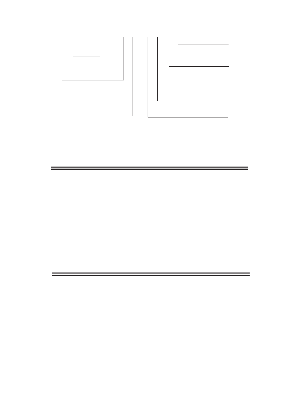
NOMENCLATURE
B HP 216 L E - T5 A - S B
B = Bally
High Profile Unit Cooler
Nominal Capacity x 1000
(standard motor/fan blade) @ 10°F TD
Application Range
H = Hi / Medium Temp 7 FPI (0°F to 35°F Evap Temp)
M = Medium Temp 6 FPI (0°F to 35°F Evap Temp)
P = Medium Temp 4 FPI (0°F to 35°F Evap Temp)
L = Low Temp 6 FPI (-5°F to -40°F Evap Temp)
V = Low Temp 4 FPI (-5°F to -40°F Evap Temp)
Defrost
A = Air
E = Electric
T = 3 Pipe Hot Gas w/ Heater
G = Reverse Cycle Hot Gas w/ Heater
H = 3 Pipe Hot gas w/ Loop
R = Reverse Cycle Hot Gas w/ Loop
STANDARD FEATURES
Throw Boosters:
N = None
B = Booster
Motor Option:
S = Standard
T = TEFC
V = High Velocity
† Not available on above
+15°F Evap. Temp. models
Generation
st
A = 1
Voltage:
T3 = 208-230/3/60
T4 = 460/3/60
T5 = 575/3/60
T7 = 200-220/3/50
T9 = 380-400/3/50
†
• Heavy gauge textured aluminum cabinet
with galvanized steel hangers, support channels
and end plates
• Hinged access panels with removable hinge
pins and captive fasteners.
• Hinged drain pan with removable hinge pins
• Rugged heavy-gauge galvanized steel rail
motor mount / support.
OPTIONAL FEATURES
• Factory mounted TX valve, solenoid valve
and thermostat
• Throw boosters
• Insulated drain pan
• St ackable design
• Schrader fitting and external equalizer line.
• Factory installed solenoid valve wire harness
• Unit shipped upright for convenient handling
and quick installation.
• TEFC motors
• Optional fin spacing
• Optional fin materials
• Optional coil coating
- 2 -
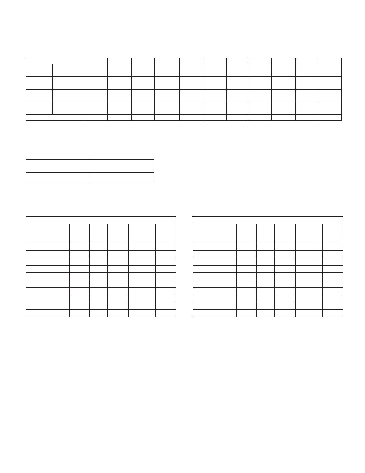
CAPACITY DATA
High and Medium Temperature Models - Capacity @ 7 F.P.I.
sledoM.pmeTmuideM/hgiHAH370AH680AH311AH031AH451AH071AH981AH332AH252AH872
yticapaC
yticapaC
yticapaC
wolFriAMFC ( )S/L
*egrahCtnaregirfeR.BL )GK(
.D.TF°1@HUTB
).D.TC°55.0@STTAW(
.D.TF°01@HUTB
).D.TC°55.5@STTAW(
.D.TF°51@HUTB
3.8@STTAW(
).D.TC°3
* Estimated, based on R404A at +25° S.S.T. with coil 30% full.
Derate capacity by 0.92 and CFM by .85 for Throw Booster Option.
0
276
)8691(
00276
)38691(
008001
)42592(
00631
)8146(
02 )9( 72 )21
0197
)7132(
00197
)86132(
056811
)35743(
00621
)6495(
( 04 )81( 04 )81( 05 )32( 06 )72( 88 )04( 89 )54( 811 )45( 751 )17(
00401
)6403(
000401
)26403(
000651
)29654(
00921
)8806(
06911
)3053(
006911
)13053(
004971
)64525(
00981
)9198(
07141
)0514(
007141
)40514(
055212
)65226(
00
502
)4769(
04651
)1854(
004651
)01854(
006432
)41786(
00591
)2029(
50Hz
09371
)4905(
009371
)53905(
058062
)30467(
00112
)7599(
04412
)0826(
004412
)89726(
006123
)79149(
00592
)12931(
08132
)9876(
008132
)49876(
007743
)148101(
00182
)06231(
08552
)2947(
008552
)42947(
007383
)683211(
00752
)82121(
Average Air Throw - ft (m)
NAFDRADNATS
ROTOMDNA
09 )72( 521 )83(
05/3/022-002
LEDOM
A7T-AH370PHB
A7T-A
H680PHB
A7T-AH311PHB
A7T-AH031PHB
A7T-AH451PHB
A7T-AH071PHB
A
7T-AH981PHB
A7T-AH332PHB
A7T-AH252PHB
A7T-AH872PHB
NAF
ROTOM
YTQ
21 6.98.0151
21 6.98.0151
25.18.113.3151
31 4.416.5102
35.17.712.9152
35.17.712.9152
+35.17.712.9152
45.16.321.5203
45.16.321.5203
45.16.321.5203
PH
ROTOM
ALF
LATOT
†
LANOITPO
RETSOOBWORHT
† Measured in open sp ace. Actual throw may be less in real
applications.
ELECTRICAL DATA
.CRIC.NIM
YTICAPMA
)A(
.XAM
ESUF
)SPMA(
680PHB
05/3/004-083
LEDOM
A9T-AH370PHB
A9T-AH
A9T-AH311PHB
A9T-AH031PHB
A9T-AH451PHB
A9T-AH071PHB
A9T-AH981PHB
A9T-AH332PHB
A9T-AH252PHB
A9T-AH872PHB
NAF
ROTOM
YTQ
21 2.47.451
21 2.47.451
25.15 6.551
31 3.68.651
35.15.71.851
35.15.71.851
+
35.15.71.851
45.1016.0151
45.1016.0151
45.1016.0151
PH
ROTOM
ALF
LATOT
.CRIC.NIM
YTICAPMA
)A(
.XAM
ESUF
)SPMA(
NOTE: 3+ indicates 3-fan “long” configuration (see dimensional data for details)
- 3 -
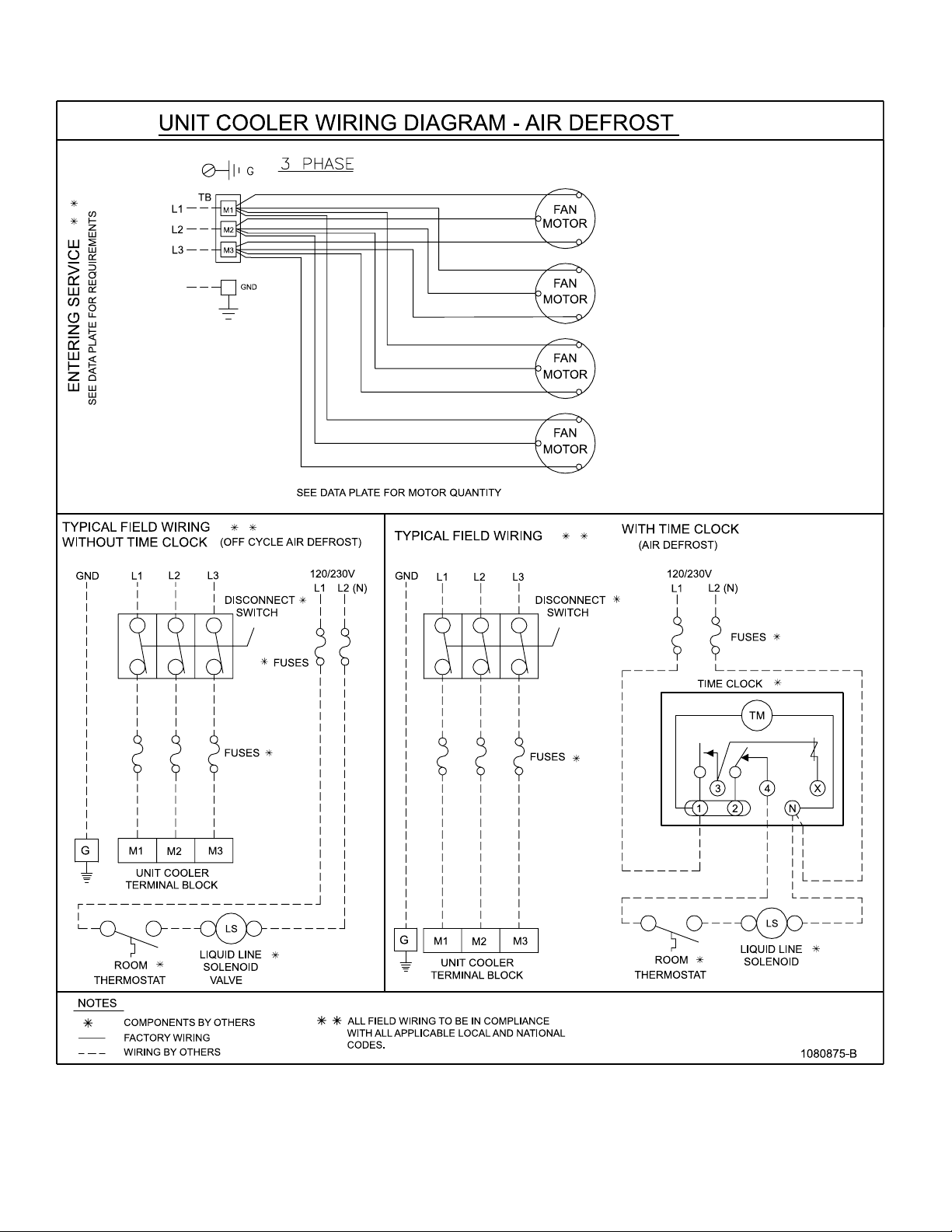
WIRING DIAGRAM
- 4 -

DIMENSIONAL DATA
2 Fan Models
Drain connections 1-1/4” FPT .
3 Fan Models
- 5 -

DIMENSIONAL DATA
3 Fan (Long) Models
Drain connections 1-1/4” FPT .
snaFfOrebmuN
.nnoCrotubirtsiD
)taewSDO(
noCnoitcuS
.n
)taewSDO(
teN.xorppA
thgieW
.BL )GK(
4 Fan Models
SPECIFICATIONS
sledoM.pmeTmuideM/hgiHAH370AH680AH311AH031AH451AH071AH981AH332AH252AH872
222 3333 4 4 4
sehcnI
)mm(
sehcnI
)mm(
8/1-1
)92(
8/5-1
)14(
076
)813(
8/3-1
)53(
8/5-1
)14(
247
)733(
8/3-1
)53(
8/1-2
)45(
738
)973(
8/3-1
)53(
8/1-2
)45(
1701
)584(
8/3-1
)53(
8/1-2
)45(
5411
)915(
8/5-1
)14(
8/1-2
)45(
8021
)845(
8/3-1
)53(
8/5-2
)76(
3921
)685(
8/3-1
)53(
8/5-2
)76(
0951
)127(
8/3-1
)53(
8/5-2
)76(
6961
)077(
8/5-1
)14(
8/5-2
)76(
9191
)078(
- 6 -

INSTALLATION INSTRUCTIONS
The installation and start-up of Unit Coolers should only
be performed by qualified refrigeration mechanics.
This equipment should be installed in accordance with
all applicable codes, ordinances and local by-laws
INSPECTION
Inspect all equipment before unpacking for visible signs of
damage or loss. Check shipping list against material
received to ensure shipment is complete.
IMPORTANT: Remember , you, the consignee, must make
any claim necessary against the transportation company .
Shipping damage or missing parts, when discovered at
the outset, will prevent later unnecessary and costly
delays.
If damage or loss during transport is evident, make
claim to carrier, as this will be their responsibility,
not the manufacturer’s.
Should carton be damaged, but damage to equipment is
not obvious, a claim should be filed for “concealed damage” with the carrier.
IMPORTANT: The electrical characteristics of the unit
should be checked at this time to make sure they correspond to those ordered and to electrical power available at
the job site.
Save all shipping papers, tags and instruction sheets for
reference by installer and owner .
LOCATION
The unit location in the room should be selected to ensure
uniform air distribution throughout the entire space to be
refrigerated. Be sure that the unit does not draw air in, or
blow directly out, through an opened door and that the
product does not obstruct the free circulation of air.
Consideration should be given to the coil location in order
to minimize the piping run length to the condensing unit
and floor drain
CLEARANCES
This evaporator draws air through the coil and discharges
air from the fan side, and thus adequate clearance should
be made on the entering face of the coil to ensure even
unrestricted air flow through the coil. This distance should
be equal to the height of the coil or more.
Ensure enough room is left at the ends of the coil for
servicing.
MOUNTING
This evaporator is supplied with shipping legs to allow
units to be shipped in an upright position. Units can be
lifted into place with shipping skid attached to mounting
legs.
Hanger brackets take up to 5/8” (15.9 mm) hanger rods.
After the evaporator is hung in place, remove the bolts
attaching the skid to the legs.
DRAIN LINE
If the evaporator is mounted flush to ceiling, the staggered hanger will provide a positive pitch for drainage.
If units are suspended below the ceiling, the installer
must provide adequate pitch to the unit by adjusting the
location of the hanger rod nuts.
Note: Check for adequate drainage by pouring water into
the drain pan.
Ensure that the drain pan has sufficient slope for
proper drainage (prevention of ice build up /
blockage in pan).
Insulated copper tube should be run from the drain
connection, sloping at least 4” (102mm) per foot. A trap
located outside of the room should be provided to
prevent warm air entering through the tubing. Connection
should be made to proper drainage facilities that comply
with local regulations.
If room temperatures are below freezing, it is necessary
to heat the drain line to prevent condensate from
freezing in the drain line. Electric heating cable or
electric tape (by others) is used for this purpose. The
drain line heater should be connected for continuous
operation; it is also recommended that the drain line be
insulated. A heat output of 20 watt s per lineal foot of 1”
(25mm) drain line in a 0°F (-18 °C) room is usually
satisfactory . 1 15 volt cable and tape is available from
your local refrigeration wholesaler. Two 1 15 volt s heaters
(by others) of the same wattage may be wired in series
for use on 230 volt system
- 7 -

INSTALLATION INSTRUCTIONS (cont’d)
PIPING
Refrigerant line sizes are important and may not be the
same size as the coil connections (depends on the
length of run). If in doubt, consult “Recommended
refrigerant line sizes” charts.
WIRING
Wire system in accordance with governing standards
and local codes. Enclosed typical wiring diagrams are
for reference only . Refer to unit data plate for operating
current, minimum ampacity and maximum fuse sizing
for fan motors.
NOTE: Electrical wiring is to be sized in accordance
with minimum ampacity rating.
For ease of identifying the proper wiring terminals, unit
wiring is colour coded and terminal block connections
are identified. When fan delay thermostats (combination fan delay and defrost termination) are installed, on
start-up, the fans do not operate until the coil temperature is reduced to approximately 20 °F (-6.7 °C). It is
normal for the fans to cycle a few times until the room
temperature is brought down. At higher evaporating
temperatures this control is of an adjustable type, and
proper adjustment is required.
The defrost termination control is adjustable and may
be set at a minimum of 40 °F (4.4 °C) (fully CW) to a
maximum of 75 °F (23.8 °C) (fully CCW). Normal setting
is 55 °F (12.8 °C). This can be increased if the defrost
heaters are terminated too soon (frost still left) or if
terminated too long (steaming of coil). Time clock
should be set for a fail-safe termination of approximately
45 minutes.
A hinged end panel provides quick access to the electrical compartment.
SYSTEM CHECK
Before Start-Up:
1. All wiring should be in accordance with local codes.
2. All refrigerant lines should be properly sized.
3. Electric defrost systems should include a liquid line
solenoid valve.
4. Thorough evacuation and dehydration has been
performed.
5. The suction, discharge and receiver service valves
must be open.
6. The system should include a liquid line drier moisture
indicator and suction filter.
7. Pour enough water into the drain pan to allow a good
check on drainage and seal the trap.
After Start-Up:
1. If necessary , temporarily by-pass fan delay control to
run fans until room temp is lowered. (Run jumper wire
from terminal N to F on circuit terminal block).
2. Check the compressor oil level to ensure the correct
oil charge.
3. Be sure that the expansion valve is properly set to
provide the correct amount of superheat (should be
around 70% of operating T .D.)
4. Heavy moisture loads are usually encountered when
starting the system for the first time. If the coil
temperature is below freezing, this will cause a
rapid build-up of frost on the coil. During the initial pull
down, frost build-up should be watched and defrosted
manually as required.
5. Check for proper evaporator fan blade rotation.
MAINTENANCE
1. Periodic checking and cleaning of the coil surface
when necessary should be done, using a whisk or
brush. Drain pans are hinged to provide convenient
access to the inside coil surface (except hot gas loop
pans).
2. Ensure coil and pan does not have any excessive ice
build-up from improper defrost operation. Any build-up
of ice can cause fins and refrigerant tubes to be
crushed. When replacing heater elements, first remove
heater slot covers and heater clips
3. Motors are permanently lubricated type and require
no further lubrication.
- 8 -

SERVICE PARTS LIST
SROTOMSLEDOM#TRAPPDO#TRAPCFET
05/3/022-002MPR058PH1031,680,37073708011470801
05/3/022-002MPR0411PH5.1 872,252,
05/3/004-083MPR058PH1031,680,37073708011470801
05/3/004-083MPR0411PH5.1 872
SEDALBNAFSLEDOM#TRAP
SROTOMPH1ROF031,680,3709470801
SROTOMPH5.1ROF872,25
.CSIMSLEDOM#TRAP
DRAUGNAFLLA4358701
SROTOM-KCOLBLANIMRETLLA7105401
332,981,071,451,31193708013470801
,252,332,981,071,451,31193708013470801
2,332,981,071,451,311 0570801
- 9 -

NOTES
- 10 -

FINISHED GOODS WARRANTY
The terms and conditions as described below in the General Warranty Policy cover all products
manufactured by National Refrigeration.
GENERAL WARRANTY POLICY
Subject to the terms and conditions hereof, the Company warrants all Products, including Service
Parts, manufactured by the Company to be free of defects in material or workmanship, under normal
use and application for a period of one (1) year from the original date of installation, or eighteen (18)
months from the date of shipment from the Company, whichever occurs first. Any replacement
part(s) so supplied will be warranted for the balance of the product’s original warranty. The part(s) to
be replaced must be made available in exchange for the replacement part(s) and reasonable proof of
the original installation date of the product must be presented in order to establish the effective date
of the warranty , failing which, the ef fective date will be based upon the date of manufacture plus thirty
(30) days. Any labour, material, refrigerant, transportation, freight or other charges incurred in connection with the performance of this warranty will be the responsibility of the owner at the current
rates and prices then in effect. This warranty may be transferred to a subsequent owner of the
product.
THIS WARRANTY DOES NOT COVER
(a) Damages caused by accident, abuse, negligence, misuse, riot, fire, flood, or Acts of God (b) damages
caused by operating the product in a corrosive atmosphere (c) damages caused by any unauthorized
alteration or repair of the system affecting the product’s reliability or performance (d) damages caused
by improper matching or application of the product or the product’s components (e) damages caused
by failing to provide routine and proper maintenance or service to the product (f) expenses incurred for
the erecting, disconnecting, or dismantling the product (g) parts used in connection with normal
maintenance, such as filters or belts (h) products no longer at the site of the original installation (i)
products installed or operated other than in accordance with the printed instructions, with the local
installation or building codes and with good trade practices (j) products lost or stolen.
No one is authorized to change this WARRANTY or to create for or on behalf of the Company any
other obligation or liability in connection with the Product(s). There is no other representation, warranty
or condition in any respect, expressed or implied, made by or binding upon the Company other than the
above or as provided by provincial or state law and which cannot be limited or excluded by such law , nor
will we be liable in any way for incidental, consequential, or special damages however caused.
The provisions of this additional written warranty are in addition to and not a modification of or subtraction
from the statutory warranties and other rights and remedies provided by Federal, Provincial or State
laws.
PROJECT INFORMATION
metsyS
rebmuNledoM pU-tratSfoetaD
rebmuNlaireS rotcartnoCecivreS
tnaregirfeRenohP
ylppuSlacirtcelExaF
- 11 -

“AS BUILT” SERVICE PARTS LIST
04/14/2008
Service Parts ListService Parts List
Service Parts List
Service Parts ListService Parts List
LL
abelabel
L
abel
LL
abelabel
TT
o Be Ao Be A
T
o Be A
TT
o Be Ao Be A
HEREHERE
HERE
HEREHERE
ttachedttached
ttached
ttachedttached
®
General Sales, PGeneral Sales, P
General Sales, P
General Sales, PGeneral Sales, P
135 Little Nine Drive, Morehead City135 Little Nine Drive, Morehead City
135 Little Nine Drive, Morehead City
135 Little Nine Drive, Morehead City135 Little Nine Drive, Morehead City
252-240-2829 • 1-800-24-BALL252-240-2829 • 1-800-24-BALL
252-240-2829 • 1-800-24-BALL
252-240-2829 • 1-800-24-BALL252-240-2829 • 1-800-24-BALL
e-mail: ballysales@ballyrefboe-mail: ballysales@ballyrefbo
e-mail: ballysales@ballyrefbo
e-mail: ballysales@ballyrefboe-mail: ballysales@ballyrefbo
Due to Manufacturer’s policy of continuous product improvement,
the Manufacturer reserves the right to make changes without notice.
arar
ts & Serts & Ser
ar
ts & Ser
arar
ts & Serts & Ser
vice Manufacturing & Engineeringvice Manufacturing & Engineering
vice Manufacturing & Engineering
vice Manufacturing & Engineeringvice Manufacturing & Engineering
xx
x
xx
, NC 28557, NC 28557
, NC 28557
, NC 28557, NC 28557
Y • FY • F
AX: 252-240-0384AX: 252-240-0384
Y • F
AX: 252-240-0384
Y • FY • F
es.com • wwwes.com • www
es.com • www
es.com • wwwes.com • www
AX: 252-240-0384AX: 252-240-0384
.ballyrefbo.ballyrefbo
.ballyrefbo
.ballyrefbo.ballyrefbo
xx
es.comes.com
x
es.com
xx
es.comes.com
DISTRIBUTED BY:
 Loading...