


OPERATOR'S MANUAL
Liquid Propane Gas (LPG) Grill
Model MEV808ALP
FREE HELP
FROM THE GRILL EXPERTS
Do not return to the store. At Grand Hall we're the experts on this product and trained to help
you with:
ŸAssembly questions
ŸGrill operation
ŸReplacement of damaged ormissingparts
visit www.grandhall.com or call:
1- 800-770-9769
Monday - Friday 8:00am-4:30pm CST
IMPORTANT:
ŸNOTETO ASSEMBLER /INSTALLER:
Leave this manual with the consumer.
ŸNOTETOCONSUMER:
Keep thismanual for future reference.
ŸRECORDYOURSERIAL#__________________
(see silver CSA label on main body of grill)
 !
!
 WARNING
 !
!
ŸFailure to comply with these instructions could result in a fire or explosion that could cause seriousbodily injury, death or property damage.
ŸWhether this grill was assembled by you or someone else, you must read this entire manual before using your grill to ensure the grill is properly assembled, installed and maintained.
ŸUse your grill at least 3 feet away from any wall or surface. Use your grill at least 3 feet away from combustible objects that can melt or catch fire such as vinyl or wood siding, fences and overhangs or sources of ignition including pilot lights on water heaters and live electrical appliances.
ŸTHISGASAPPLIANCEISDESIGNEDFOROUTDOORUSEONLY.
ŸNever use your gas grill in a garage, porch, shed, breezeway or any other enclosed area.
ŸNever obstruct the flow of ventilation air around your gas grill housing.
ŸNever disconnect the gas regulator or any gas fitting while your grill is lit. A lit grill can ignite leaking gas and cause a fire or explosion which could result in property damage, personal injury or death.
Manual # P80162004F - Date:2007/11/15

|
Table |
of |
Contents |
|
||
Primary Safety Warnings ........................... |
1-3 |
|||||
Pre-Assembly |
Instructions.............................. |
3 |
||||
Part Diagrams |
and |
Lists .......................... |
4-6 |
|||
Assembly |
Instructions............................... |
7-10 |
||||
Use & Care |
Instructions: |
|
||||
• |
Gas Safety and Leak Tests........... |
11-13 |
||||
• |
Lighting |
Instructions ................................. |
14 |
|||
• |
Troubleshooting |
.......................................... |
|
15 |
||
• |
Cleaning |
and |
Maintenance ................ |
16-17 |
||
• |
Frequently Asked |
Questions ............ |
A2-A3 |
|||
Warranty Terms............................ |
|
Back |
Cover |
|||
! |
DANGER |
! |
IF YOU SMELL GAS:
1.Shut off gas to the appliance.
2.Extinguish any open flame.
3.Open lid.
4.If odor continues, keep away from the appliance and immediately call your gas supplier or your fire department.
 !
!
 WARNING
 !
!
1.Do not store or use gasoline or other flammable liquids or vapors in the vicinity of this or any other appliance.
2.An LP cylinder not connected for use shall not be stored in the vicinity of this or any other appliance.
 !
!
 WARNING
 !
!
•LPG grill models must be used with Liquid Propane Gas and the regulator assembly supplied. Natural Gas models must be used with Natural Gas only. Any attempt to convert
the grill from one fuel type to another is extremely hazardous and will void the warranty.
•Keep gas regulator hose away from hot grill surfaces and dripping grease. Avoid unnecessary twisting of hose. Visually inspect hose prior to each use for cuts, cracks, excessive wear or other damage. If the hose appears damaged do not use the gas grill. Call Grand Hall at 1-800-770-9769 for a certified replacement hose.
•California Proposition 65
Combustion byproductsproduced whenusing this product contain chemicals known to the State of California to cause cancer, birth defects, or other reproductive harm.
Brass components on the grill, such as hose fittings, propane cylinder valves (sold separately) and burner valve stems, contain lead which is known to the State of California to cause cancer, birthdefects, or other reproductiveharm.
•Never use charcoal or lighter fluid in this gas grill. Failure to comply with these instructions could result in a grease fire or explosion that could cause serious bodily injury, death or propertydamage.
•TheGrease Draining Tray and Grease Receptacle must be visually inspected before each grill use. RemoveanygreaseandwashGrease Draining Tray and Grease Receptacle with a mild soap and warm water solution. Failure to comply with these instructions could result in a grease fire or explosion that could cause serious bodilyinjury, death or property damage.
2

Pre-Assembly Instructions For Your Safety
 !
!
 WARNING
 !
!
Failure to comply with these instructions could result in a fire or explosion that could cause serious bodily injury, death or property damage.
Spiders and small insects can spin webs and nest in the grill Burner Tubes during transit and warehousing which can lead to a gas flow obstruction resulting in a fire in and around the Burner Tubes. This type of "FLASHBACK FIRE" can cause serious grill damage and create an unsafe operating condition for the user.
To reduce the chance of FLASHBACK FIRE you must clean the Burner Tubes as follows before assembling your grill.
Also do this at least once a month in summer and fall or whenever spiders are active in your area, and if your grill has not been used for an extended period of time.
1.Remove the screw from the rear of each Burner using a Phillips Head Screwdriver.
2.Carefully lift each Burner up and away from the Gas Valve Orifice.
3.Check and clean Burner/Venturi Tubes for insects and insect nests. A clogged tube can lead to a fire beneath the grill.
4.Refer to the figure below and perform one of these 3 cleaning methods:
METHOD 1: Bend a stiff wire or wire coat hanger into a small hook as shown and run the hook through the Burner Tube and inside the Burner several times to remove debris.
TO CLEAN BURNER
TUBE,INSERT HOOK Burner Port
HERE
9 


Burner Foot
METHOD 2: Use a bottle brush with a flexible handle and run the brush through the Burner Tube and inside the Burner several times to remove any debris.
METHOD 3: Use an air hose to force air through each Burner Tube. The forced air should pass debris or obstructions through the Burner and out the Ports.
For safe operation ensure the Gas Valve Assembly Orifice is inside the Burner Tube before using your grill. See figure. If the Orifice is not inside the Burner Tube, lighting the Burner may cause explosion and/or fire resulting in serious bodily injury and/or property damage.
Gas Valve
To expedite the assembly process follow these general guidelines:
Tools Required for Assembly:
•protective work gloves
•protective eyewear
•Phillips Head Screwdriver
 You will need assistance from another person to handle the grill head and other large, heavy parts.
 Open Lid of shipping carton and remove top sheet of cardboard and / or packing materials. Lay cardboard sheet on floor and use as a work surface to protect floor and grill parts from scratches.
 You may slice the carton front corners with a utility knife to lay open the carton front panel. This allows you to raise the grill head Lid and remove the components packed inside, making it easier to lift.
 Use the Hardware and Part Diagrams to ensure all items are included and free of damage.
 Do not assemble or operate the grill if it appears damaged. If there are damaged or missing parts when you unpack the shipping box or you have questions during the assembly process, call the:
GrillInformationCenter1-800-770-9769
8am-4:30pm CST, Monday through Friday
 NOTE: This gas grill is designed to be used with two 20lb LP Gas tanks (not included) for 8 burner operation. A tank placed on the right will operate the four right-side burners. A tank placed on the left will operate the four left-side burners.
Grill Installation Codes
The installation must conform with local codes or, in the absence of local codes, with the National Fuel Gas Code, ANSI Z223.1/NFPA 54, or the Natural Gas and Propane Installation Code, CSA B149.1, as applicable, including: 1. The appliance and its individual shutoff valve must be
disconnected from the gas supply piping system during any pressure testing of that system at test pressures in excess of 1/2 psi (3.5 kPa).
2. The appliance must be isolated from the gas supply piping system by closing its individual manual shutoff valve during any pressure testing of the gas supply piping system at test pressure equal to or less than 1/2 psi (3.5 kPa).
Orifice
3
Hardware Pack Parts List for Model MEV808ALP
The following table illustrates a breakdown of the |
hardware pack. It highlights what parts are used in |
||||
the various stages of assembly. |
|
|
|
||
|
|
|
|
|
|
|
PART # |
PART DESCRIPTION |
|
QTY |
PURPOSE OF PART |
|
|
|
|
|
|
|
P06002030A |
Hardware Pack |
|
1 |
For use in assembly |
|
|
|
|
|
|
|
S112G0306A |
Phillips Head Screw 3/16"x3/8" |
|
4 |
Secures the Lid Handle on the Left and Right Lid |
|
|
|
|
|
|
|
S112G0408A |
Phillips Head Screw 1/4"x1/2" |
|
12 |
Secures the Bowl Handle on the Left and Right Bowl |
|
|
|
|
|
Support Bracket |
|
|
|
|
|
|
|
S196G0408A |
Thumbscrew 1/4"x1/2" |
|
4 |
Secures the Tank Holders on the Cart Frame |
|
S411G0408A |
Plain Washer 1/4" |
|
4 |
|
|
|
|
|||
|
|
|
|
|
|
|
S112G0408A |
Phillips Head Screw 1/4"x1/2" |
|
16 |
Secures the Casters on the Cart Frame |
|
|
|
|
|
|
Hardware Pack Diagram for Model MEV808ALP
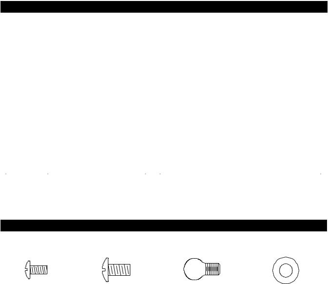
Phillips |
Head Screw 3/16"x3/8" |
Phillips |
Head Screw 1/4"x1/2" |
Thumbscrew 1/4"x1/2" |
Plain |
Washer 1/4" |
QTY. 4 |
|
QTY. 28 |
QTY. 4 |
QTY. 4 |
||
Part # |
S112G0306A |
Part # |
S112G0408A |
Part # S196G0408A |
Part |
# S411G0408A |
* Two Batteries/AA included in the Hardware Pack.
4

|
Parts |
Diagram |
for |
Model |
MEV808ALP |
|
|
|
1 |
|
|
|
|
|
|
3 |
|
|
2 |
|
|
|
4 |
|
|
|
|
|
|
5 |
|
|
|
|
|
|
6 |
|
|
|
|
|
|
7 |
|
|
|
|
|
|
8 |
|
|
|
|
|
|
9 |
|
|
|
|
|
|
10 |
|
|
45 |
|
|
|
48 |
|
|
|
|
44 |
|
|
|
|
42 |
|
13 |
|
|
|
|
11 |
|
16 |
|
|
|
|
|
|
|
|
|
|
14 |
|
|
|
|
|
|
|
15 |
|
|
|
|
|
|
|
|
47 |
24 |
|
22 |
12 |
|
17 |
|
|
|
18 |
|||
26 |
|
|
|
|
|
|
27 |
|
|
|
25 |
21 20 46 |
19 |
28B |
|
|
|
|
||
|
|
|
23 |
|
||
28A |
|
|
29 |
|
|
|
|
41 |
|
|
|
|
|
|
|
|
|
|
|
|
|
|
|
|
|
30 |
|
|
33 |
|
|
|
31 |
|
|
|
|
|
20 |
|
|
|
|
|
|
|
|
|
|
|
|
|
|
32 |
|
|
|
|
|
|
34 |
|
|
|
|
|
|
35 |
|
|
36 |
20 |
|
|
|
39 |
|
37 |
|
38 |
|
|
|
|
|
40 |
43 |
|
|
5

Parts List for Model MEV808ALP
KEY |
PART DESCRIPTION |
PART # |
QTY |
1 |
Lid, Left |
P00127045K |
1 |
2 |
Lid, Right |
P00128045K |
1 |
3 |
Lid Handle |
P00203006M |
2 |
4 |
C ooking Grid |
P01601002E |
3 |
5 |
Savor PlateT M |
P01705018E |
8 |
6 |
Burner |
P020080234 |
8 |
7 |
Gas Collector Box with Electrode |
P02609012B |
8 |
8 |
Burner Bracket |
P022160184 |
1 |
9 |
Greas e Tray Heat Shield |
P06903044A |
2 |
10 |
Wind Shield As sem bly |
Y0480002 |
1 |
11 |
Bowl Panel, Rear |
P0072520JA |
1 |
12 |
Bowl Panel, Front |
P0075701JA |
1 |
13 |
Bowl Panel, Left |
P0072020JA |
1 |
14 |
Bowl Panel, Right |
P0072120JA |
1 |
15 |
Bowl Support Bracket, Right |
P01306024D |
1 |
16 |
Electric Wire Set |
P02615044A |
1 |
17 |
Lighting Stick |
P05313009B |
2 |
18 |
Bowl Handle |
P00203024D |
2 |
19 |
Protective Pad |
P05518010I |
4 |
20 |
Latch As s em bly |
P05517002L |
8 |
21 |
H os e Bracket |
P05341001G |
2 |
22 |
Gas Valve/Manifold As s em bly Bracket |
P03324004H |
1 |
23 |
R egulator w ith H os e/Tw o Stage (LPG) |
P03624004A |
2 |
24 |
Gas Valve / Manifold As s em bly, Left |
Y0060496 |
1 |
25 |
Gas Valve / Manifold As s em bly, Right |
Y0060497 |
1 |
26 |
C ontrol Panel , Upper |
P02911058I |
1 |
27 |
C ontrol Panel , Low er |
P02911911L |
1 |
28A |
C ontrol Knob |
P03411111K |
8 |
28B |
C ontrol Knob Seat |
P03415014S |
8 |
29 |
Electric Ignitor, 4-port |
P02502164C |
2 |
30 |
Greas e Tray |
P02717065B |
1 |
31 |
Greas e Receptacle |
P02701065B |
2 |
32 |
Tank Hook |
P04001007C |
2 |
33 |
C art Leg, Left |
P00901056C |
1 |
34 |
C art Leg, Right |
P00902056C |
1 |
35 |
C art Fram e Bracket |
P03334002D |
2 |
36 |
C art Fram e |
P03335002D |
1 |
37 |
C art Seat |
P04518001A |
4 |
38 |
Tank Holder |
P04002007C |
2 |
39 |
C as ter, 4 in., without Brake |
P05120001D |
2 |
40 |
C as ter, 4 in., with Brake |
P05120002D |
2 |
41 |
N am e Plate |
P00402060A |
1 |
42 |
Savor PlateT M Bracket |
P033280524 |
16 |
43 |
Greas e Tray Bracket, Lower |
P05330014G |
2 |
44 |
Bowl Seat |
P04524003A |
4 |
45 |
Bowl Bracket |
P03304026H |
1 |
46 |
Lighting Stick Bracket |
P05528003O |
2 |
47 |
Electric Ignitor Protector Bracket |
P03327048Q |
2 |
48 |
Bowl Support Bracket, Left |
P01306025D |
1 |
|
C over |
P07007047A |
1 |
|
Operator's Manual |
P80162004H |
1 |
|
H ardware Pack |
P06002030A |
1 |
For the repair or replacement parts you need call our Grill Information Center at 1-800-770-9769
To |
obtain the correct replacement parts for your gas grill, |
please refer to the part |
numbers in this parts |
|
list. |
The following information is required to ensure you receive the correct parts: |
|
||
1. |
Model and Serial Number (see CSA label on grill) |
|
|
|
2. |
Part |
Number |
|
|
3. |
Part |
Description |
|
|
4. |
Quantity of parts needed |
|
|
|
Important: Use only factory authorized parts. The use of any part that is not factory authorized can be |
||||
dangerous and will also void your product warranty. Keep |
this Operator's Manual |
for convenient referral |
||
and for |
part replacement. |
|
|
|
6
1
2
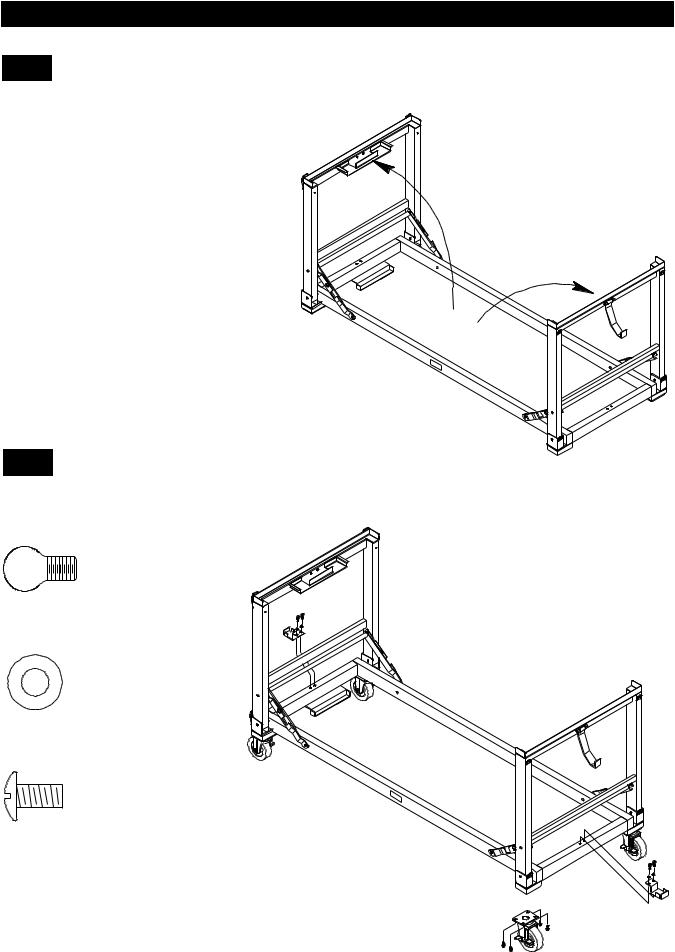
Assembly Instructions
Assemble Cart
 With an assistant, lift Cart out of shipping carton and place it on the cardboard work surface.
 Unfold the Cart Legs and straighten the Cart Frame Bracket until a click sound is heard. CAUTION: Do not stand, lean or apply pressure to the Cart Frame Bracket once assembled.
Install Tank Holders and Casters
 Install Tank Holders to each side of Cart Frame. Tighten securely using 4 Thumbscrews and washers.
 Install Casters to each Cart Leg.
Tighten securely using 16 Phillips Head Screws.
Thumbscrew 1/4"x1/2"
QTY. 4
Part # S196G0408A
Plain Washer 1/4"
QTY. 4
Part # S411G0408A
Phillips Head Screw 1/4"x1/2"
QTY. 16
Part # S112G0408A
Casters Installation Code
The installation shall be made with a connector that complies with the Standard for Connectors for Movable Gas Appliances, ANSI Z21.69-CSA6.16.
7

3 |
Install Handles |
Install Lid Handles to Left and Right Lid. |
Tighten securely using 4 Phillips Head Screws 3/16"x3/8".  Install Bowl Handles to each Bowl Support Bracket.
Tighten securely using 12 Phillips Head Screws1/4"x1/2".
Phillips Head Screw 3/16"x3/8"
QTY. 4
Part # S112G0306A
Phillips Head Screw 1/4"x1/2"
QTY. 12
Part # S112G0408A
4 |
Install Grill Bowl |
With an assistant, lift and position Grill Bowl onto the Cart. |
Lock 4 Latches on Grill Bowl and Cart.
8

5 |
Assemble and Install Grease Tray |
Position Grease Receptacles to the Holders under Grease Tray. |
 Slide the assembled Grease Tray side tabs over the side brackets on the Grill Cart Legs. The Grease Tray is required to be present and centered for your safety.
Grease Tray
FREE HELP FROM THE GRILL EXPERTS. At Grand Hall we're the experts on this product and trained to help you with assembly and grill operation or if there are damaged or missing parts when you unpack this unit from the shipping box. Do not return to the store.
GRILL INFORMATION CENTER
Visit www.grandhall.com or call 1-800-770-9769 Monday - Friday 8:00am - 4:30pm CST
9
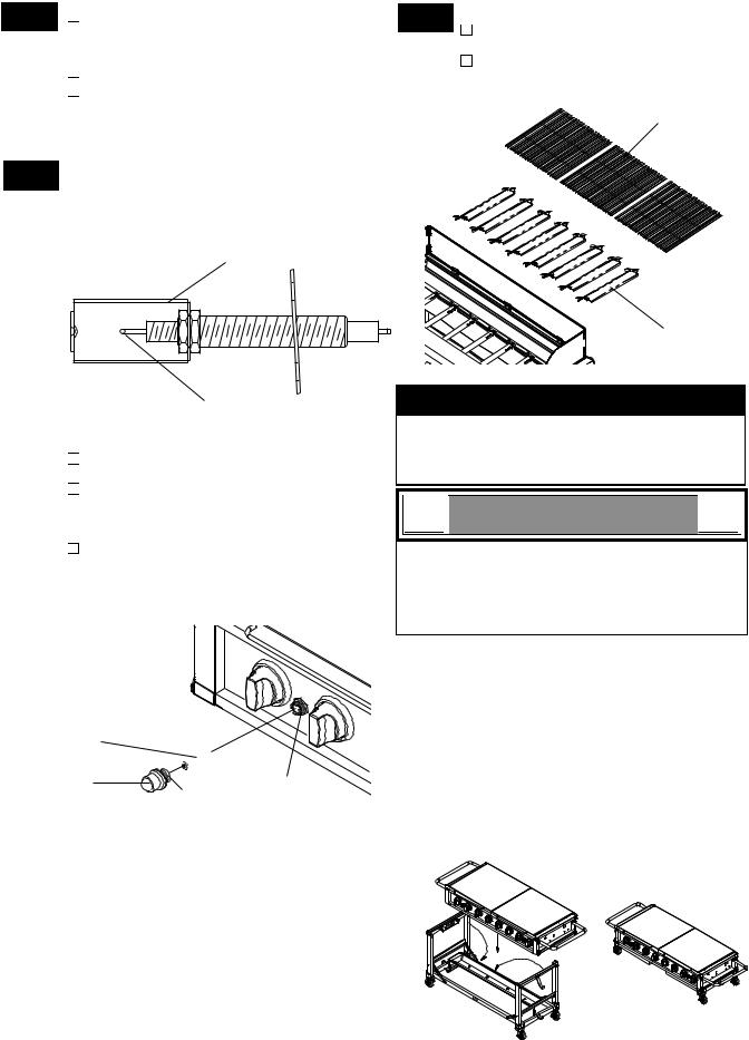
6 |
Install Ignitor Batteries |
|
|
8 |
Install Cooking Components |
|
Unscrew Ignitor Cap from |
Control |
Panel. |
Place |
the Savor Plates TM on lower ledge |
||
|
Place supplied AA battery |
into the |
Ignitor |
|
above |
Burners. |
|
Slot with positive pole facing you. |
|
|
|||
|
|
|
Place |
Cooking Grids on bowl ledge. |
||
|
Position the Cap and Spring over the AA |
|
||||
|
|
|
|
|||
|
battery and tighten onto Control Panel. |
|
|
|
||
|
Repeat to install the other AA battery |
|
|
Cooking Grids |
||
|
into the Ignitor Slot. |
|
|
|
|
|
7 |
With the |
assistance of another person, |
perform |
this Electrode Check before |
proceeding.
This test will ensure that the Spark Electrode Tips are properly positioned so your grill lights easily and properly.
Gas Collector Box
Spark Electrode Tip
Be sure all Control Knobs are set to "OFF" and open the Grill Lids.
Have your assistant stand behind to the right of the grill and look toward the front
of the |
grill |
bowl. Never put your face |
||
inside |
the |
Grill Head. |
|
|
Press |
the |
Ignitor Cap. You should hear |
||
a "clicking" |
sound. |
Your |
assistant should |
|
see a |
blue spark |
within |
each Gas |
|
Collector Box. If a spark is present the Electrode Tips are properly positioned.
AA Battery

 -
-
Ignitor Cap |
+ |
Ignitor Slot |
|
Spring |
|
If no spark is seen, the Spark Gap needs to be adjusted as follows
•If the gap between the Spark Electrode Tip and Receiver is more than 3/16" use long nose pliers to gently squeeze the Gas Collector Box to narrow gap.
•Recheck the Electrode again, if no "clicking" sound is heard:
AA Battery is installed backwards.
-Electric wires may be loose. Remove the AA Battery and inspect the Ignitor
Junction Box found behind the Control
Panel and reconnect any loose wires.-
Savor PlateTM
Final Grill Assembly Step
When you have finished assembling your grill be sure that all screws are tightened for safe operation of your grill.
 !
!
 WARNING
 !
!
Failure to read and follow the Use and Care Instructions could result in a fire or explosion that could cause serious bodily injury, death or property damage.
Transporting or Storing your grill:
1.Lock grill Casters.
2.Remove LP Gas tank and Grease Tray from your grill. Place Grease Tray on Lower Grease Tray Bracket. See Fig.1.
3.Loosen 4 Latches on Grill Bowl and Cart. With an assistant, lift and position Grill Bowl on a cardboard surface.
4.Fold the Cart Legs onto Cart Frame. See Fig.1.
5.With an assistant, lift and position Grill Bowl onto the folded Cart. See Fig.1.
Lock 4 Latches on Grill Bowl and Cart. See Fig.2.
6.Be sure grill is secured tightly and covered when being transported.
Fig. 1 |
Fig. 2 |
10
USE AND CARE INSTRUCTIONS
CORRECT LP GAS TANK USE
LP Gas grill models are designed for use with two standard 20 lb. Liquid Propane Gas (LP Gas) tanks, not included with grill. Never connect your gas grill to an LP Gas tank that exceeds this capacity. A tank of approximately 12 inches in diameter by 18-1/2 inches high is the maximum size LP Gas tank to use. You must use an "OPD" gas tank which offers a listed Overfill Prevention Device. This safety feature prevents tank from being overfilled which can cause malfunction of LP Gas tank, regulator and/or grill.
The LP Gas tank must be constructed and marked in accordance with the Specifications for LP-Gas Cylinders of the U.S. Department of Transportation (D.O.T.) or the National Standard of Canada, CAN/ CSA-B339, Cylinders, Spheres and Tubes for Transportation of Dangerous Goods; and Commission, as applicable.
The LP Gas tank must have a shutoff valve, terminating in an LP Gas supply tank valve outlet, that is compatible with a Type 1 tank connection device. The LP Gas tank must also have a safety relief device that has a direct connection with the vapor space of the tank.
The tank supply system must be arranged for vapor withdrawal.
The LP Gas |
tank |
used must have a collar |
to protect the |
tank |
valve. |
Never connect an unregulated LP gas tank to your gas grill. The gas regulator assembly supplied with your gas grill is adjusted to have an outlet pressure of 11" water column (W.C.) for connection to an LP gas tank. Only use the regulator and hose assembly supplied with your gas grill. Replacement regulators and hose assemblies must be those specified by the Manufacturer.
Have your LP Gas dealer check the release valve after every filling to ensure it remains free of defects.
Always keep LP Gas tank in upright position.
Do not subject the LP Gas tank to excessive heat.
Never store an LP Gas tank indoors. If you store your gas grill in the garage always disconnect the LP Gas tank first and store it safely outside.
LP Gas tanks must be stored outdoors in a wellventilated area and out of the reach of children.
Disconnected LP Gas tanks must not be stored in a building, garage or any other enclosed area.
The regulator and hose assembly can be seen after opening the doors (if applicable) and must be inspected before each use of the grill. If there is excessive abrasion or wear or if the hose is cut, it must be replaced prior to using the grill again.
Never light your gas grill with the lid closed or before checking to ensure the burner tubes are fully seated over the gas valve orifices.
Never allow children to operate your grill. Do not allow children or pets to play near your grill.
Use of alcohol, prescription or non-prescription drugs can impair your ability to properly assemble and safely operate your grill.
 Keep fire extinguisher readily accessible. In the event of a oil/grease fire, do not attempt to extinguish with water. Use type B extinguisher or smother with dirt, sand or baking soda.
 Keep your grill covered during freezing rain or snow. Sleet and snow can block the regulator vent
hole |
resulting in improper and potentially dangero- |
us |
regulator pressure. |
 Use your grill on a level, stable surface in an area clear of combustible materials.
 Do not leave grill unattended when in use.
 Do not move the appliance when in use.
 Cover your grill when not in use.
 Allow the grill to cool before moving or storing.
  Do not use your grill as a heater.
 This grill is not intended to be installed in or on recreational vehicles and/or boats.
 !
!
 WARNING
 !
!
A.Do not store a spare LP-Gas tank under or near this appliance.
B. Never fill the tank beyond 80 percent full; and
C.If the information in "(a)" and "(b)" is not followed exactly, a fire causing death or serious injury may occur.
! |
WARNING |
! |
• Use your grill at least 3 feet away from any wall or surface. Use your grill at least 3 feet
|
away |
from combustible |
objects that can melt |
|
or catch fire such as vinyl or wood siding, |
||
|
fences and overhangs or sources of ignition |
||
|
including pilot lights on water heaters and live |
||
• |
electrical appliances. |
|
|
Outdoor cooking gas appliance shall not be |
|||
|
used |
under overhead |
combustible construction. |
•Never use your gas grill in a garage, porch, shed, breezeway or any other enclosed area.
•Never obstruct the flow of ventilation air around
your gas grill housing.
•In windy conditions, always position the front of grill to face oncoming wind to reduce smoke and heat blowing in your face and prevent potential hazards to self and grill.
3ft. |
3ft. |
|
WIND |
DIRECTION |
11

USE AND CARE INSTRUCTIONS
NOTE about LP Gas Tank Exchange Programs
ŸMany retailers that sell grills offer you the option of replacing your empty LP Gas tank through an exchange service. Use only those reputable exchange companies that inspect, precision fill, test and certify their tanks. Exchange your tank only for an OPD safety featureequipped tank as described in the LP Gas tank section of this manual.
ŸAlways keep new and exchanged LP Gas tanks in an upright position during use, transit or storage.
ŸLeak test new and exchange LP Gas tanks BEFORE connecting one to your grill.
How to Leak Test your LP Gas Tank
For your safety:
ŸAll leak tests must be repeated each time your LP Gas tank is exchanged of refilled.
ŸWhen checking for gas leaks do not smoke.
ŸDo not use an open flame to check for gas leaks.
ŸYour grill must be leak tested outdoors in a wellventilated area, away from ignition sources such as gas fired or electrical appliances. During the leak test, keep your grill away from open flames or sparks.
ŸDo not use household cleaning agents. Damage to gas assembly components can result.
Use a clean paintbrush and a 50/50 mild soap and water solution.
Brush soapy solution onto LP Gas tank in the areas indicated by the arrows. See diagram.
If growing bubbles appear do not use or move the LP Gas tank. Call an LP Gas Supplier or your Fire Department.
! |
|
WARNING |
! |
If |
growing bubbles appear do not use or move |
||
the LP Gas tank. Contact an LP Gas Supplier
or |
your fire department! |
|
|
! |
|
|
|
|
WARNING |
! |
|
Before using this gas appliance read all instructions and perform all gas leak-check procedures even if the product was pre-assembled by the retailer or manufacturer.
LP Gas Model only:
Secure two 20lb LP Gas Tanks to Gas Grill
Turn your LP Gas Tank Valves clockwise to the closed or OFF positon.
Hang your gas tanks on the top Tank Hooks. The ring foot of the gas tanks will rest on the Tank Holder.
Cylinders Installation Code
The handling, storage, and transporation of all sizes of gas cylinders must be in accordance with ANSI/NFPA 58, Storage and Handling of liquid Petroleum Gases, or the CSA B149.1, Natural Gas and Propane Installation Code.
LP Gas Model only:
Connect Regulator with Hose to your LPG Tanks
Turn all Burner Valves to the OFF position.
Inspect the valve connection port and regulator assembly for damage or debris. Remove any debris. Never use damaged or plugged equipment.
Connect the regulator assembly to the tank valve and HAND TIGHTEN nut clockwise to a full stop. DO NOT use a wrench to tighten because it could damage the Quick Coupling Nut and result in a hazardous condition.
Open the tank valve fully (counterclockwise) and use a soapy water solution to check all connections for leaks before attempting to light
your |
grill. See |
"Checking for LP Gas Leaks". |
If a |
leak is found, turn the tank valve off and |
|
do not use your |
grill until the leak is repaired. |
|
|
|
Type 1 connection per |
|
|
ANSI Z83.11-2006 |
|
|
Quick |
|
|
Coupling Nut |
CAUTION: When the appliance is not in use the gas must be turned off at the tanks.
12

USE AND CARE INSTRUCTIONS
Check all connections for LP Gas Leaks
Never |
test for leaks |
with |
a flame. Prior to first use, |
at the |
beginning of |
each |
season, or every time |
your LP Gas tank is changed, you must check for gas leaks. Follow these three steps:
 Make a soap solution by mixing one part liquid detergent and one part water.
 Turn the grill Control Knobs to the full OFF position, then turn the gas ON at source.
 Apply the soap solution to all gas connections indicated by the arrows. See diagram. If bubbles appear in the soap solution the connections are not properly sealed. Check each fitting and tighten or repair as necessary.
CAUTION: Always open both left and right Lids as shown before lighting your grill.
Two Stage Regulator |
Lock Casters while |
|
with Hose (LPG) |
||
your grill is in use |
||
|
LP Gas Tank
Gas Valve / Manifold Assembly
 !
!
 WARNING
 !
!
If you have a gas leak that cannot be repaired by tightening, turn off the gas at the source, disconnect fuel line from your grill and call 1-800-770-9769 or your gas supplier for repair assistance.
Never disconnect the gas regulator or any gas fitting while your grill is lit. A lit grill can ignite leaking gas and cause a fire or explosion which could result in property damage, personal injury or death.
Disconnecting A Liquid Propane Gas (LPG) Tank From Your Grill
 Make sure the Burner Valves and LP Gas tank valve are off. (Turn clockwise to close.)
 Detach the hose and regulator assembly from the
LP Gas tank valve by turning the Quick Coupling
Nut counterclockwise.
13
 Loading...