

Baja WD250U Service Manual

WD250U Service Manual
For any questions please contact Baja Motorsports at 888-863-2252

Content
Content...........................................................................................................................2
Chapter I General description........................................................................................6
Section 2 Special tools, instruments & meters.............................................................. 7
(I) Special tools....................................................................................................7
Section 3 Identication code, label of model and engine No........................................9
Section 4 Points for attention in maintenance................................................................9
Section 5 Specication................................................................................................. 13
I. How to use conversion table of unit............................................................... 13
(1) How to use conversion table........................................................................ 13
(2) Denition of unit..........................................................................................13
II. Basic specication.........................................................................................14
III. ATV body..................................................................................................... 15
IV. Electric system............................................................................................. 16
V. Maintenance specication of engine............................................................. 18
Section 6 Wiring diagram of ATV................................................................................ 21
(I) Technical explanation and requirement, details of relative component........ 21
(II) Wiring diagram (1)...................................................................................... 23
(III) Wiring diagram (2)..................................................................................... 24
(IV) Wiring diagram (3)..................................................................................... 25
Section 7 Requirements for torque of fastener............................................................. 26
(1) ATV body..................................................................................................... 26
(2) Engine.......................................................................................................... 28
(3) General torque specication........................................................................ 30
Section 8 Lubrication................................................................................................... 31
(1) Lubrication oil way........................................................................................31
(2) Lubrication diagram..................................................................................... 32
Section 9 Lubrication point and type of lubricants...................................................... 34
(1) ATV body..................................................................................................... 34
(2) Engine.......................................................................................................... 35
Chapter II Maintenance and adjustment of vehicle...................................................... 36
Section 1 Periodic maintenance/lubrication................................................................ 36
Section 2 Disassembly and assembly of cushion, fender and fuel tank....................... 37
(I) Cushion......................................................................................................... 37
(II) Rear fender.................................................................................................. 38
(III) Fuel tank..................................................................................................... 40
(IV) Front fender................................................................................................ 42
2

Section 3 Maintenance and adjustment of vehicle body.................................................................... 44
(I) Wear inspection of front and rear brake............................................................................ 44
(II) Adjustment of front brake..................................................................................................44
(III) Adjustment of free clearance of left lever and rear brake pedal.......................................45
(IV) Position adjustment of steering lever............................................................................. 47
(V) Lubricating oil level inspection of rear driving gearcase................................................. 47
(VI) Replacement of engine oil of rear driving gearcase....................................................... 48
(VII) Rubber sleeve inspection of rear wheel fork................................................................. 49
(VIII) Inspection of steering system....................................................................................... 49
(IX) Adjustment of toe-in of front wheel............................................................................... 50
(X) Inspection of front/rear shock absorber........................................................................... 51
(XI) Adjustment of rear shock absorber............................................................................... 51
(XII) Inspection of tire.......................................................................................................... 52
(XIII) Inspection of rim........................................................................................................ 53
Section 4 Maintenance and adjustment of electrical appliance......................................................... 54
(I) Inspection of battery......................................................................................................... 54
(II) Inspection of fuse............................................................................................................ 55
(III) Replacement of headlight lamp.......................................................................................56
Section 5 Maintenance and adjustment of engine.............................................................................. 58
(I) Adjustment of clutch......................................................................................................... 58
(II) Cleaning of air lter.........................................................................................................58
(III) Inspection of spark plug................................................................................................. 60
(IV) Adjustment of idle speed.............................................................................................. 61
(V) Adjustment of free clearance of throttle grip................................................................. 61
(VI) Adjustment of speed limiter........................................................................................... 62
(VII) Adjustment of valve clearance.................................................................................... 63
(VIII) Adjustment of timing chain tension.............................................................................65
(IX) Inspection of ignition timing........................................................................................ 66
(X) Measuring of compressive force..................................................................................... 67
(XI) Inspection oil quantity of engine................................................................................... 68
(XII) Replacement of engine oil and inspection of oil ow.................................................. 69
Chapter III Repair and maintenance of vehicle body.........................................................................71
Section 1 Rear driving gearcase and driving shaft.............................................................................71
(I) Troubleshooting.................................................................................................................72
(II) Inspection.........................................................................................................................72
(III) Troubleshooting table.....................................................................................................73
(IV) Disassembly.................................................................................................................. 74
(V) Inspection.........................................................................................................................77
(VI) Pad choice of main driving gear and shift gear............................................................ 79
(VII) Installation....................................................................................................................80
3

Section 3 Rear wheel/Rear brake/Rear wheel axle................................................................ 81
(I) Removal steps....................................................................................................... 83
(II) Inspection stepes.................................................................................................. 85
(III) Installation steps................................................................................................. 88
Section 4 Steering operation system...................................................................................... 92
(I) Removal steps of steering bar................................................................................ 93
(II) Removal steps of steering vertical column welding............................................ 94
(III) Inspection content............................................................................................... 95
(IV) Installation steps................................................................................................. 96
(V) Installation steps of steering bar.......................................................................... 99
Section 5 Front shock absorber and front wheel fork............................................................ 100
(I) Disassembly........................................................................................................... 101
(II) Inspection steps.................................................................................................... 103
(III) Installment steps................................................................................................. 104
Section 6 Rear shock absorber and rear wheel fork............................................................... 107
(I) Disassembling steps.............................................................................................. 108
(II) Checking steps..................................................................................................... 110
(III) Mounting steps................................................................................................... 112
Chapter IV Electric appliance................................................................................................ 115
Section 1 Electric assembly.................................................................................................... 115
Section 2 Inspect switch......................................................................................................... 116
(I) Inspect switch........................................................................................................ 116
(II) Inspect the switch circuit..................................................................................... 117
Section 3 Check headlight lamp............................................................................................. 118
Wire diagram.............................................................................................................. 119
Section 4 Troubleshooting the ignition system failure........................................................... 120
Section 5 Running starting circuit.......................................................................................... 124
Section 6 Troubleshooting electric starting system................................................................ 125
Section 7 Starting motor......................................................................................................... 128
Section 8 Check starting motor............................................................................................... 129
Section 9 Battery will not hold charge.................................................................................... 131
Section 10 Troubleshooting.................................................................................................... 133
Section 11 Inspection of lighting system................................................................................ 135
(I) Headlight not working........................................................................................... 135
(II) Taillight not working............................................................................................ 136
Section 12 Troubleshooting.................................................................................................... 137
(I) If indicated lamp is out of work............................................................................. 137
Section 13 Inspection of signal system.................................................................................. 139
(I) If the neutral indicated lamp is out work............................................................... 139
(II) If the reverse indicated lamp is out work............................................................. 140
(III) If the HB indicated lamp is out work.................................................................. 141
Chapter V Engine................................................................................................................... 142
Section 1 Disassembly of Engine........................................................................................... 142
(I) Remove the engine from nished ATV.................................................................. 142
(II) Disassembly of engine......................................................................................... 145
4

Section 2 Inspection and maintanence of engine............................................................................... 159
Section 3 Assembly and adjustment of engine................................................................................... 183
(I) Closing assembly of left & right crankcase...................................................................... 183
(II) Assembly of right crankcase............................................................................................ 187
(III) Assembly of left crankcase............................................................................................. 196
(IV) Selection and installation of adjusting washer............................................................... 207
(V) Assembly of cylinder head.............................................................................................. 209
(VI) Manual starting mechanism and others.......................................................................... 209
(VII) Mount the engine on the nished vehicle..................................................................... 219
Chapter VI Vehicle Troubleshooting.................................................................................................. 220
(I) Starting trouble/difculty................................................................................................... 227
5
Chapter I General Description
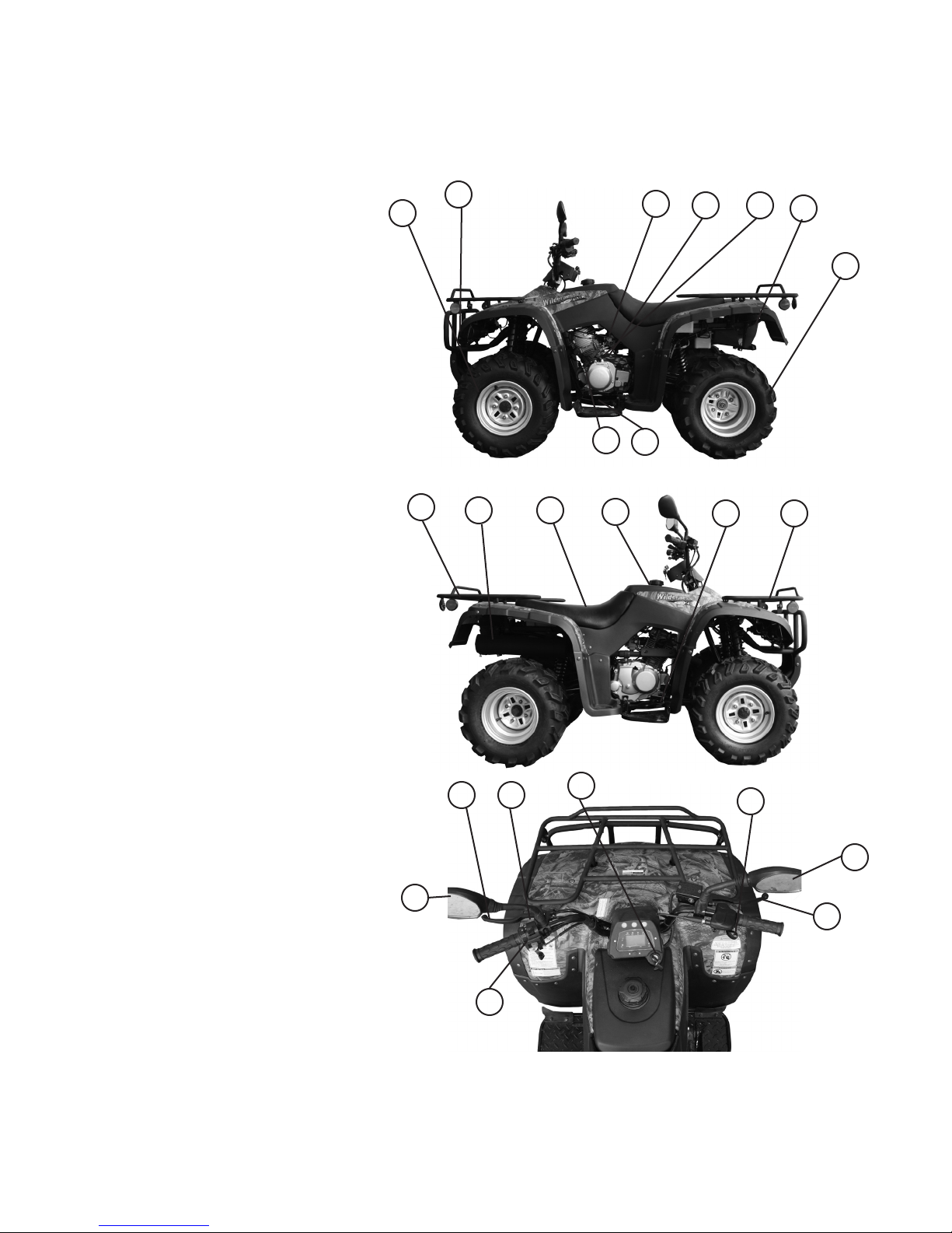
Section 1 Description
1. Front wheel
2. Headlight
3. Forward/Reverse lever
4. Shift pedal
5. Fuel valve
6. Hand-operated lever
7. Air choke
8. Taillight
9. Rear wheel
10. Rear luggage carrier
11. Exhaust silencer
12. Cushion
13. Fuel tank cover
14. Rear brake pedal
15. Front luggage carrier
16. Left rear brake lever
17. Hand-operated parking brake
18. Main switch lock
19. Throttle grip
20. Right front brake lever
21. Left switch unit
22. Left and right mirror
2
1
3
10
11 12 13
16 17
18
5
4
6 7
14 15
19
8
9
22
CAUTION:
The ATV you purchased may be slightly different from the pictures in the
manual due to improvements.
22
20
21
6

Section 2 Special tools, instruments and meters
(I) Special tools
There are special tools needed to properly adjust and assemble this unit. These tools are
intended to prevent maintenance defects and damage.
1. Wrench for valve adjustment, mainly used to adjusting the valve clearance. Specication:
3mm, 90890-01311
2. Puller for piston pin, used for removing piston pin.
3. Remover for rotator, mainly for pulling the magneto rotator from crank.
4. Clamp for rotator, for clamping magneto rotator when removing it to prevent it’s rotation due
to torque force.
5. Stop rotating meter for rotator, used for removing and assembling rotator of kick starter.
6. Puller for crank, for disassembling crank from crankcase.
7. Puller for rocker shaft, used for the removing rocker shaft.
8. Compressing tools for spring of valve, for xing and compressing spring when assembling
valve lock clamp.
9. Assembling and disassembling tools for valve guide.
10. Assembling buffer, used for assembling crank and balancing gear.
11. Hollow sleeve, for assembling crank and balancing gear.
12. Assembling tool for crank, used for assembling crank and balancing gear.
13. Assembling and disassembling joint for universal coupling.
14. Assembling and disassembling disc, used for assembling and disassembling reverse gear.
15. Fixed puller for gear.
7
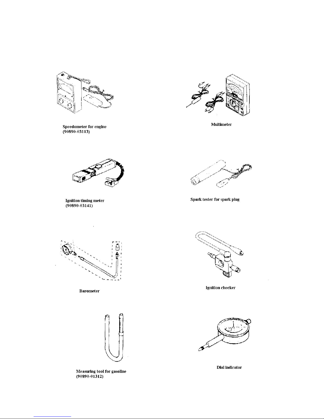
(II) Instruments and meters
The following instruments and meters can be selected with
reference to the same type of vehicle.
8
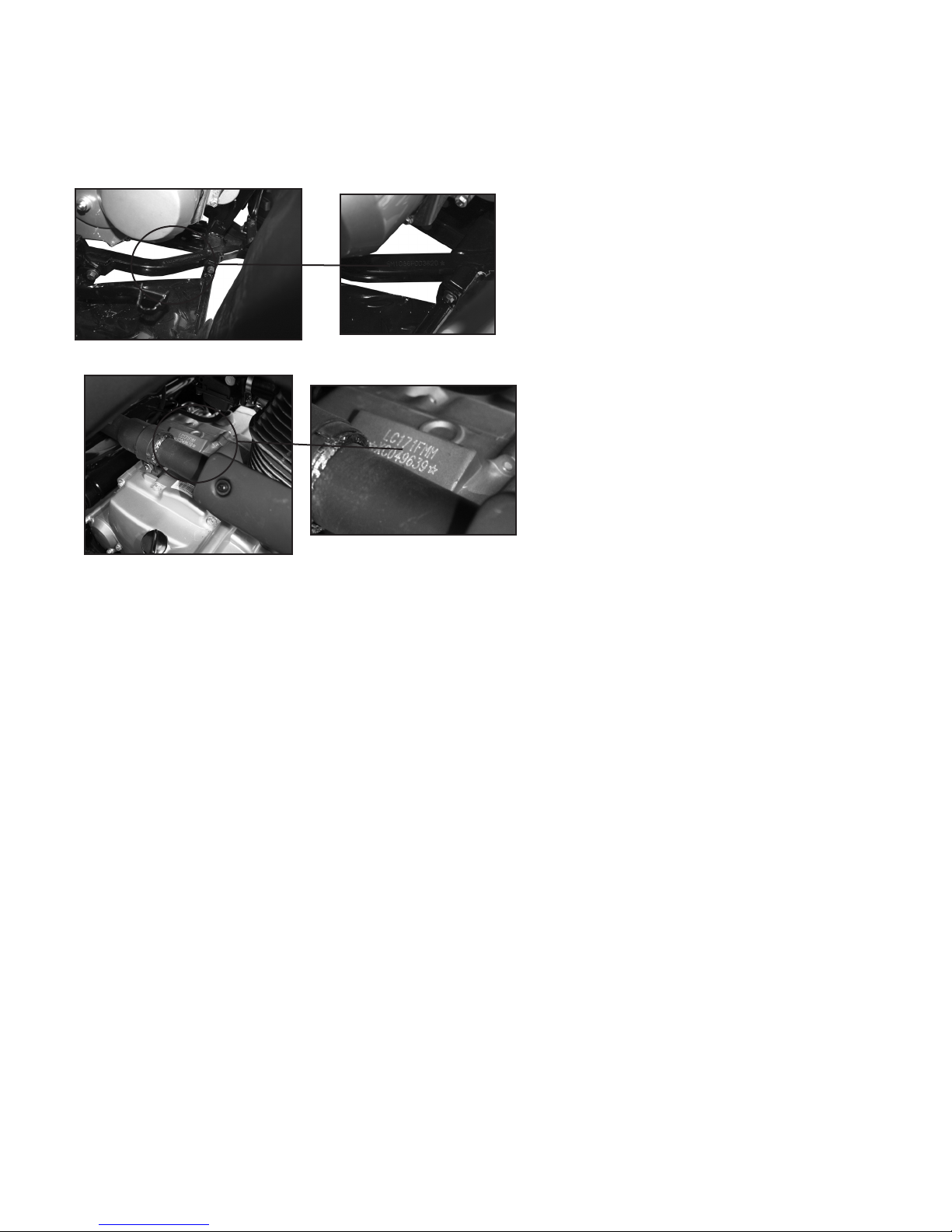
Section 3 Identication code, label
of model and engine No.
Identication code
Engraved in the left or right side of the front
supporting main tube of engine of frame
Engine No.
This is engraved on the top middle part of the
right crankcase of engine.
Section 4 Points for attention in maintenance
1. Preparation when disassembling
1.1 First clean the dirt and mud from the vehicle before removing or disassebmling.
1.2 Use proper cleaning device and tools.
1.3 Keep all the components away from re. Pay attention to hot surfaces such as the engine,
exhuast etc.
1.4 When disassembling the ATV, keep alike parts such as gear pairs, cylinder, piston, etc.
together. When assembling or replacing these components they should be kept in pairs.
1.5 When disassembling the engine, clean all components and place in a tray in the order of disassembly, not only increasing the assembling speed, but also ensuring the correct assembly.
2. Replace the components
When replacing components use only the products, lubricants and grease recommened by manufacturer.
3. Oil seal, shim, O-ring, clip, split pin, elastic washer
3.1 When disassembling to maintain the engine, to ensure that the reassembled engine has good
sealing and connected parts are xed and reliable, the oil seal, shim, o-ring, clip, split pin and
elastic washer should be replaced, be sure to keep lip of oil seal, surface of shim and o-ring in a
clean condition.
3.2 When reassembling, apply lubricant to all the alike components and bearings,
apply grease for oil seal.
9
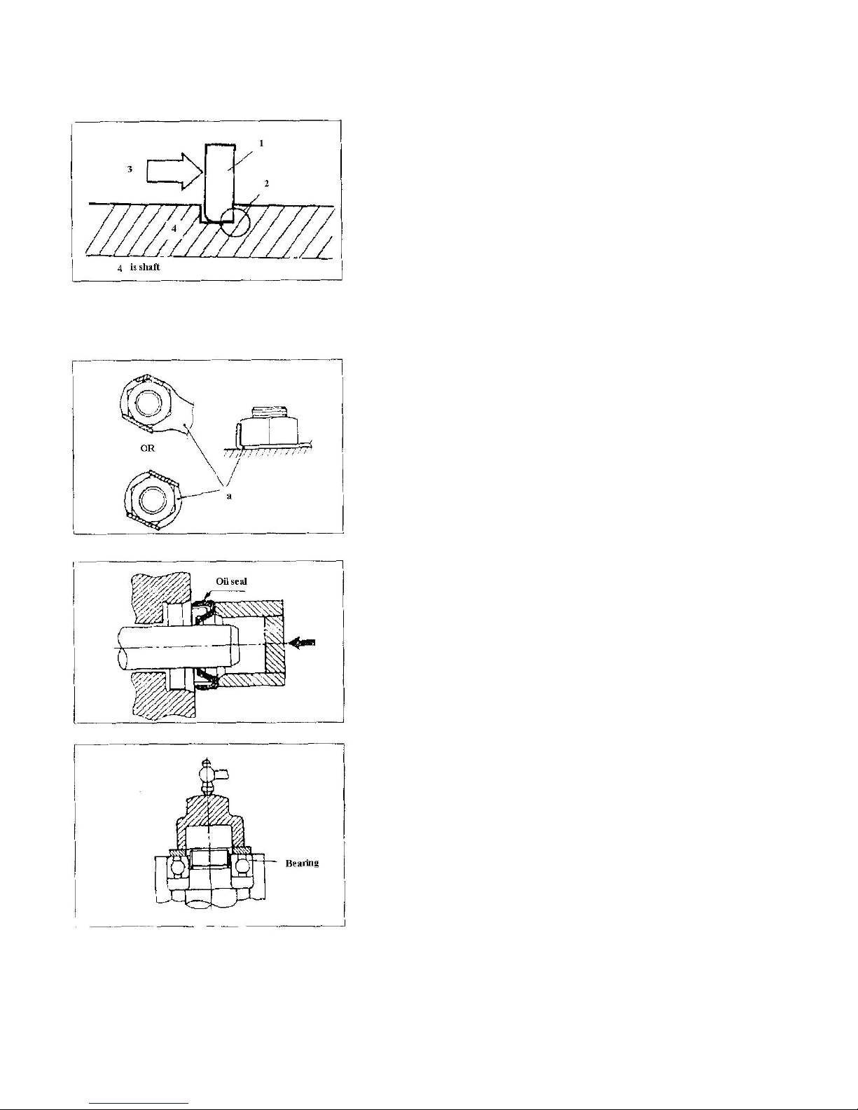
4. Clip
4.1 Before assembling, check all the clips carefully.
Replace with a new one after removing from piston
pin. When mounting clip ring (1), make the sharp
end face (2) on the opposite position of
impacted face (3) of clip. (see gure at left)
5. Locking washer/shim and location pin
5.1 When reassembling, replace all locking washer/
shim and location pin (a) . After bolt or nut is in the
lock position, bend and x both ends of locking shim
along head of bolt or direction of nut.
6. Bearing and oil seal
6.1 When assembling bearing and oil seal, put the
mark (specication of manufacturer) outside. When
assembling oil seal, apply a thin layer of lithiumbased grease on the lip of oil seal.
CAUTION:
Do not dry inside of bearing by blowing out with
compressed air, this will cause damage to the surface
of the bearing.
10
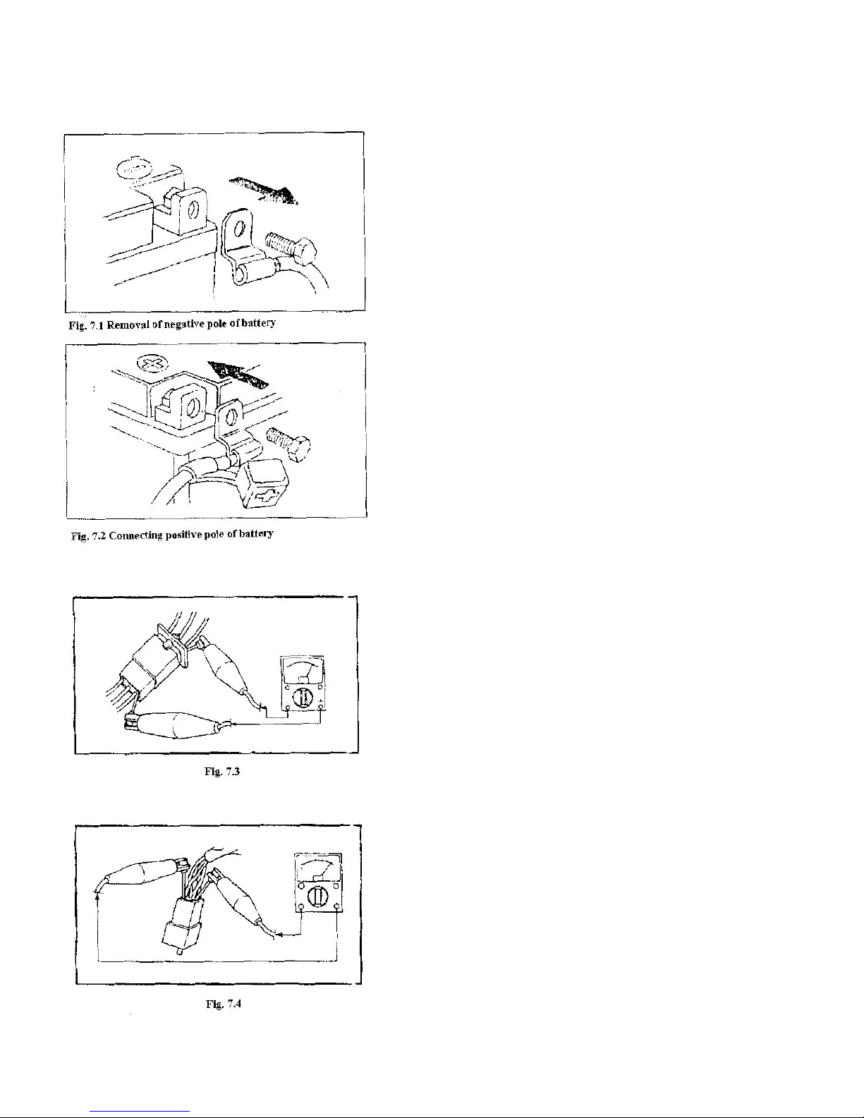
7. Check of electric parts
7.1 Make sure there is no rust, dirt or moisture at the
connection, if there is blow it dry or clean.
7.2 The electrolyte inside the battery is corrosive,
take extra precautions as to not get this on your
body.
7.3 When repairing wires on electrical parts, remove
the wire on the terminal of negative pole of battery
(see gure 7.1). When tightening or loosening bolt
on terminal of battery, do not let the wrench contact
the engine or other metal parts of the vehicle body to
avoid electric shock.
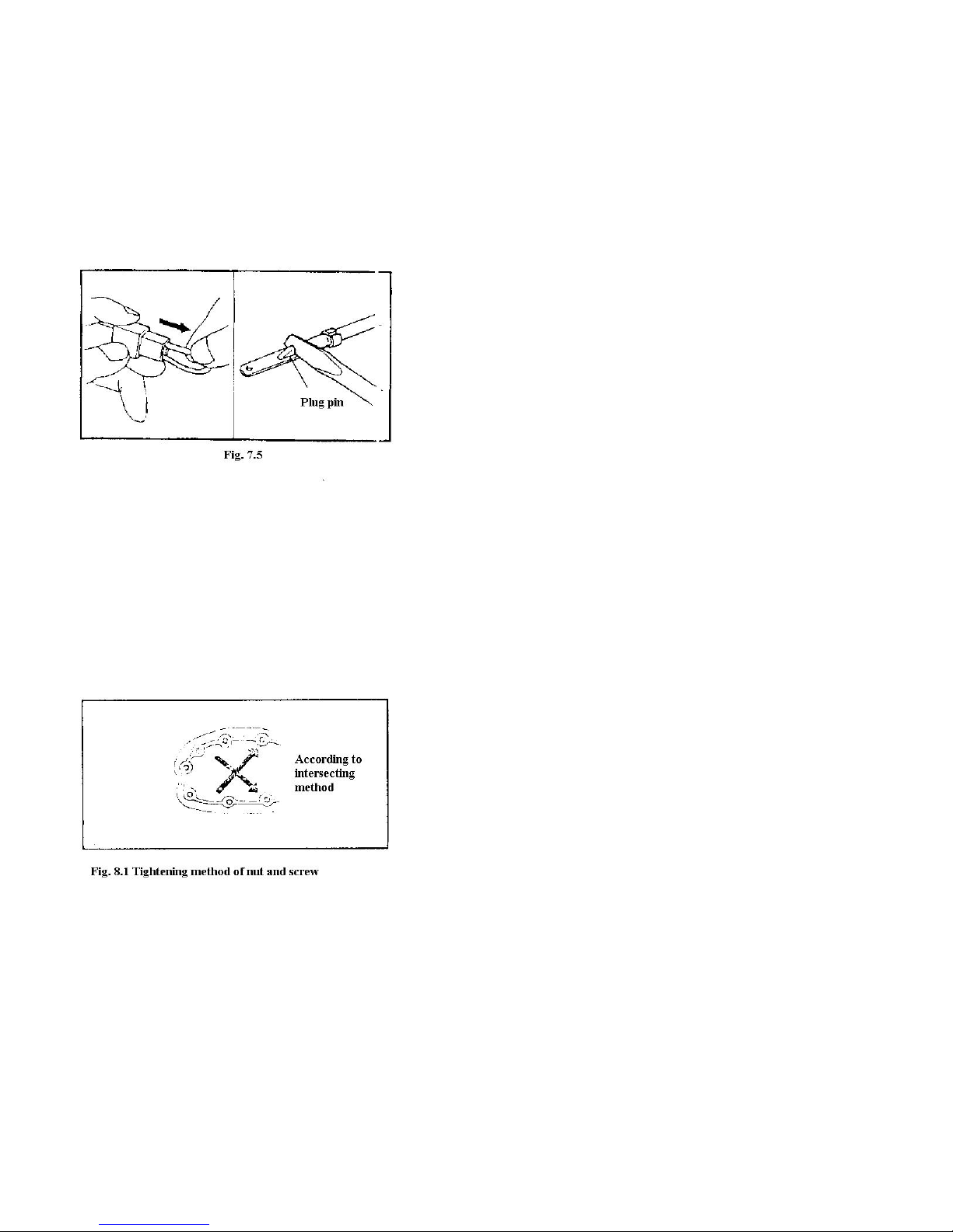
7.4 When connecting the wire to battery, rst connect the positive pole then connect the negative pole.
After wires are connected, apply clean grease on the
terminal to increase resistence of rust.
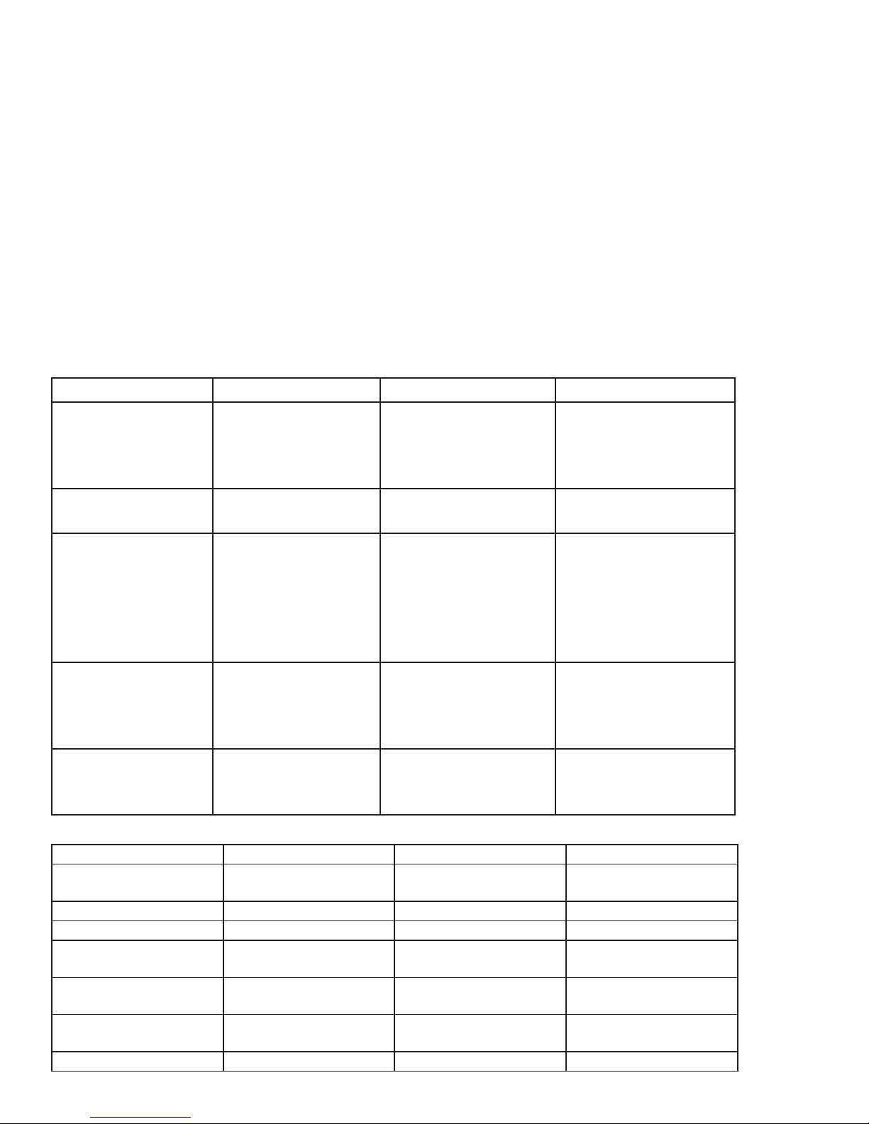
7.5 Check the terminal of connector
A. Grip the two terminals of connector together,
check with the multimeter (see gures 7.3 and 7.4)
11
B. If there is slack in the joint, bend the plug pin
upward, then connect with connector plug (see gure
7.5)
7.6 Before mounting the new fuse, check if the load
of fuse on the components are correct, especially the
portion being broken regularly, then mount the fuse
having proper current value.
7.7 There are two kinds of wire connectors, a single-
head connector, another a multi-head connector.
Before connecting single-head connector, make sure
there are no defects on the housing of the joints.
When inserting the joint, after defects are xed, put
plastic coating on.
In general, multi-head connectors are plastic and
designed to lock. When disassembling the connector,
rst open lock; when connecting again make sure the
joints are in good condition and there are no bends
or twists. After connecting, align the lock device and
lock.
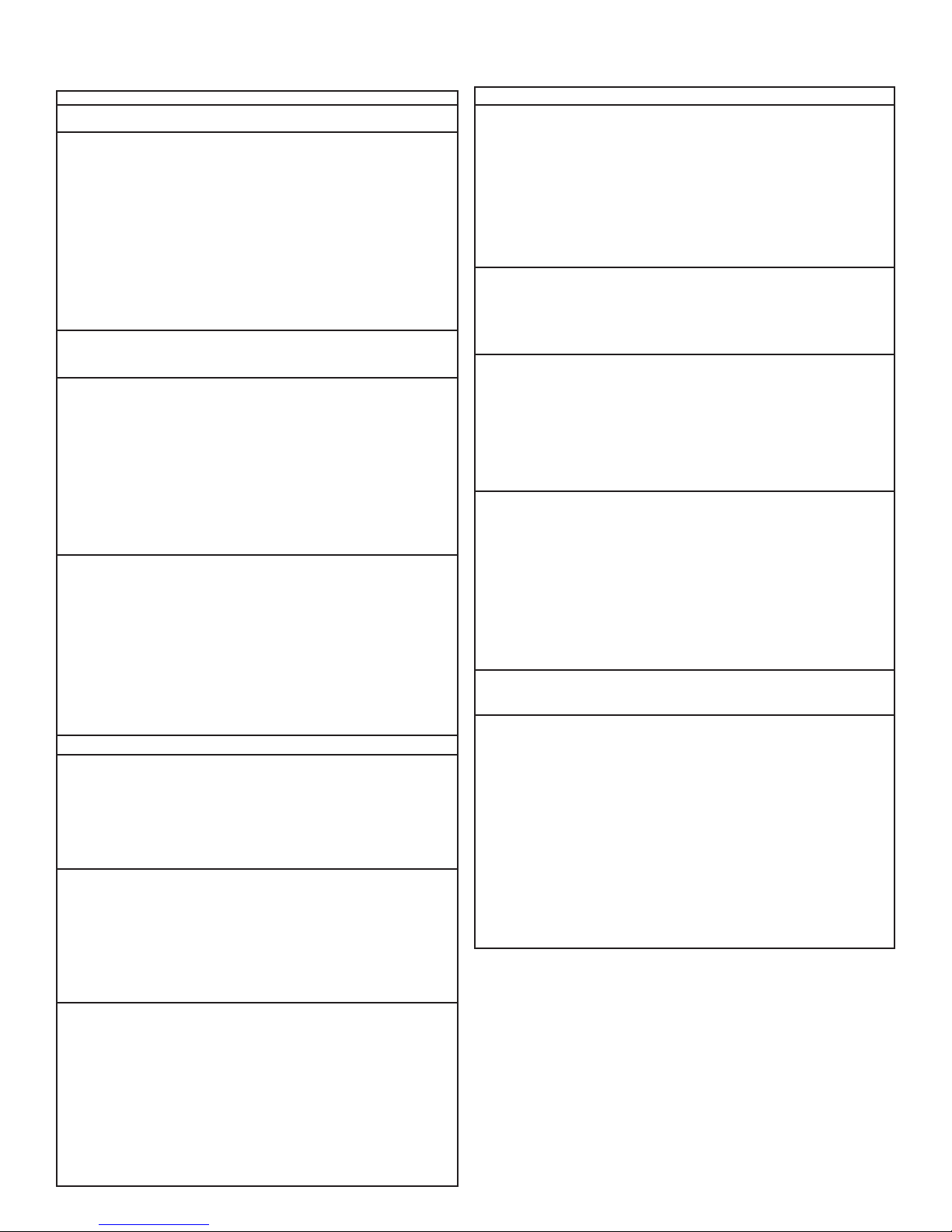
8. Use torque spanner to tighten screw and nut, and
as per specied torque. It should be tightened in
steps from big to small, from inside to outside and
along the direction of a diagonal line that intersects
(see gure 8.1).
12
Section5Specication
I. How to use conversion table of unit
(1) How to use a conversion table
All the specied documents in this manual are taken SI and Metric as unit. With the following
conversion table, metric unit could ne conversed into imperial unit.
Metric Multiply Imperial
mm 0.03937 in
2mm x 0.03937 = 0.08in
Conversion Table
Known Unit Multiply Product
Torque m•kg
m•kg
cm•kg
cm•kg
Weight kg
g
Length km/hr
km
m
m
cm
mm
Volume/capacity cc(cm³)
cc(cm²)
lit(liter)
lit(liter)
Others kg/mm
kg/cm²
Centrigrade
7.233
86.794
0.0723
0.8679
2.205
0.03527
06.214
0.6214
3.281
1.094
0.3937
0.03937
0.03527
0.06102
0.8799
0.2199
55.997
14.2234
9/5(˚C)+32
ft.lb
in•lb
ft•lb
in•lb
lb
oz
mph
mi
ft
yd
in
in
oz(IMP lig.)
cu•in
qt(IMP lig.)
gal(IMP liq.)
lb/in
psi(lb/in2)
Fahrenheit(˚F)
(2) Denition of unit
Unit Read Denition Measurement
mm
cm
kg kilogram 10³Gram Weight
N Newton 1 lilo x meter/second Force
Nm
m•kg
Pa
N/mm
L
cm³
r/min Revolutions per minute − Rotational speed
Millimeter
Centimeter
Newton meter
Meter kilogram
Pascal
Newton per millimeter
Liter
Cubic centimeter ¯ ¯
10ֿ³Meter
10ֿ²Meter
Newton x meter
Meter x kilo
Newton x meter²
Newton/centimeter
13
Length
Length
Torque
Torque
Pressure
Rigid of spring
II.Basicspecication
Item Specications
Dimension:
Overall length 1960mm
Overall width 1010mm
Overall height 1120mm
Height of cushion 780mm
Axle base 1160mm
Front wheel distance 785mm
Rear wheel distance 770mm
Min.ground clearance 155mm
Min.turning radius 2900mm
Basic weight:
Engine oil(with full tank) 220kg
Engine Single-cylinder, 4
stroke, air cooled
Displacement 229.6cm³
Cylinder bore x stroke 71 x 58mm
Compression ratio 8.7:1
Starting system Electric starter or
handoperated starter
Lubrication system Pressure splash
Engien oil SAE20W40,
SAE10W30,
SAE5W30
Classication of Model SE,SF,SG or
recommended engine oil above
Periodic oil replacement 1.5L
Replace lter 1.6L
Overall capacity 1.8L
Oil capacity of gearbox 0.27L
Model: SAE80API”GL-4”
gear oil of standard
double curved face
Capacity of fuel tank 12L, Non-lead gas #90
Capacity of reserve fuel tank 1.6L
Carburetor:
Type Vacuum lm type
Type of spark plug D7RTC
Clearance of spark plug 0.6-0.7mm
Type of clutch Wet automatic
centrifugal type
Output
Primary reduction system Gear driving
Reduction ratio 73/22(3.318)
Secondary reduction system Axle driving
Reduction ratio 19/18x46/11(4.414)
Output type Non-cycle,5 gear
forward, gear back
Operation Left-foot operation
Item Specications
Shifting type
1st speed 34/12(2.833)
2nd speed 34/19(1.789)
3rd speed 29/22(1.318)
4th speed 26/25(1.040)
5th speed 23/28(0.821)
Reverse gear 73/22x34/12x19/18x46/11(41.5)
Frame
Bracket Steel tube
Caster angle 13˚
Toe-in of tire 0-5mm
Tire
Type Vacuum
Spec. of front wheel AT22x7-10
Spec. of rear wheel AT22x10-10
Pressure of front wheel 20kpa
Pressure of rear wheel 25kpa
Brake
Type of front brake Drum(full-closed)
Operation Right-hand
Type of rear brake Drum(full-closed)
Operation Left-hand and right foot
Front suspension Independent
Rear suspension Center shock absorber
Spec. of shock absorber
Front shock absorber Spring/oil pressure
Rear shock absorber Spring/oil pressure
Electric system
Ignition system C.D.I
Magneto system A.C. magneto
Battery/capacity Free of maintenance,
12N14-BS/12V, 14AH
Headlight 12V, 25W/25Wx2
Taillight 12V,10Wx1
Neutral indicator 12V,3Wx1
Reverse indicator 12V,3Wx1
High-beam indicator 12V,3Wx1
14
III. ATV body
Item Standard Limit
Front
Wheel
Front Brake
Rear
Wheel
Rear
Brake
Steering system
Type of steering bearing
Type Spock rim, tubeless tire
Material of rim Steel plate
Size of tire AT22x7-10
Size of rim AT 10x5.5
Radial runout of rim 2.0mm
Lateral swing of rim 2.0mm
Type Hydraulic disc
Type Spoke rim, tubeless tire
Material of rim Steel plate
Sixe of tire AT22x10-10
Size of rim AT 10x8.0
Radial runout of rim 2.0mm
Lateral swing of rim 2.0mm
Type Drum type
Outside diameter of brake drum 160mm 161mm
Thickness of friction piece 4.0mm 2.0mm
Powder metallurgy sliding
bearing
Free length of back spring of brake
shoe
Free play of brake lever (left) 5-7mm
Brake lever
and brake
pedal
Free play of brake lever (right) 5-7mm
Free play of rear brake pedal 20-30mm
Free play of throttle grip 3-5mm
71.0mm
15
III. ATV body
Item Specication Limit
Elastic coefcient of spring K1 10N/mm/0-117mm
Front suspension
system
Rear suspension
system
Rear wheel fork
Free length of suspending spring 293mm
Stroke of shock absorber 117mm
Pre-tension force of spring is
adjustable or not
Elastic coefcient K2 49N/mm/8-85mm
Free length of suspending spring 263mm
Assembling length 244mm
Stroke of shock absorber 85mm
Pre-tension force of spring is
adjustable or not
Assembling free play (left-end) 1.0mm
Assembling free play (right-end) 1.0mm
IV. Electric system
Not adjustable
Adjustable
Spark plug
Ignition coil
Ignition system
Item Standard
Voltage of electric system 12V
Type D7RTC
Resistence 10Ω
Clearance of spark plug 0.6-0.7mm
Resistence of primary coil At 20˚C(68˚F), 0.5-1.5Ω
Resistence of secondary oil At 20˚C(68 ˚F), 4.6-7.6Ω
Clearance of min. spark 6mm(0.24in)
Ignition timming (before upper
stop point
Advancing angle of ignition (before ipper stop point)
Type of ignition advance
10˚/2300r/min
30˚/4300r/min
16
IV. Electric system
Item Standard
Resistence of induction coil/color At 20˚C (68˚F), 189-231Ω Blue-black
Magneto
Resistence of source coil/color At 20˚C (68˚F), 470-530Ω yellow/green-red
Type of C.D.I. Electric capacity contactless type
Rectier
Charging
system
Battery
Broken
circuit of
system
Relay of cutoff current
Electric start-
ing motor
system
Electric
starting relay
system
No-loading adjusting voltage 14.1-14.9V
Voltage-resisting value 200V
Type A·C magneto
Rated output voltage At 2000r/min 14-15V
Coil resistence/color At 20˚C (68˚F) 1.0-1.2˚ white-white
Specic gravity 1.28
Type/capacity 12N14-BS/12V, 14Ah
Type Fuse
Main fuse 20A
Reserved fuse 20A
Coil resistence At 20˚C (68˚F), 72-88Ω
Diode Yes
Type Constant mesh type
Output power 0.35KW
Resistence of armature coils At 20˚C (68˚F), 0.004-0.005Ω
Ampere 100A
coils resistence At 20˚C (68˚F), 4.8-5.3Ω
17
V.MaintenanceSpecicationofEngine
Item Standard Limit
Axle Drive
Meshing clearance of last end gear
Meshing clearance of middle gear (forward)
Meshing clearance of middle gear (backward)
Lubrication system:
Type of oil lter
Type of oil pump
Clearance of side
Endface clearance “A” or “B”
Releasing pressure of safety valve
Cylinder
Bore size
0.1-0.2mm
0.1-0.2mm
0.10-0.25mm
Wire lter net
Rotor type, pressure splash type lubrication
0.04-0.09mm
0.15mm
80-120Kpa
70.97-71.02mm
(Distance between measuring point and
upper endface of cylinder is 40mm) 71.10mm
0.09mm
0.20mm
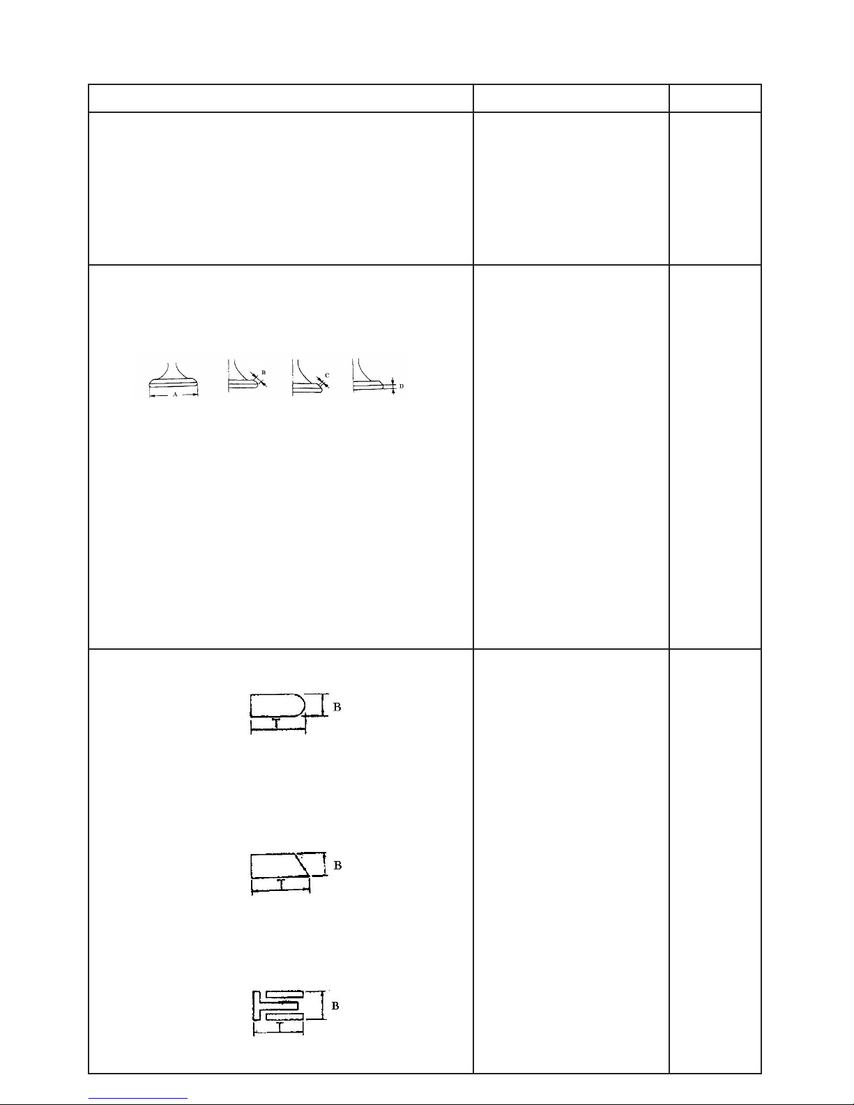
Cylinder head
Flatness of lower endface
Timing chain
Type of timing chain
Tension type of timing chain
Pneumatic camshaft:
Driving method
Roundness tolerance of camshaft
Outside diameter of camshaft
Cam size
Exhaust: A
B
C
Intake: A
B
C
Rocker arm/ Rocker arm shaft
Outside diameter of shaft
Inside diameter of rocker arm
Clearance between arm and shaft
Valve spring
Inside spring
Free length:intake/exhaust
Setting length when valve is closed:intake/exhaust
Compressing pressure when assembling:intake/exhaust
Limit value of squareness:intake/exhaust
Twisting direction of spring(topview):intake/exhaust
Measure the surface warp of every portion
on the lower endface of cylinder head with
ruler.
Roller chain
Free adjustment
Chain driven
24.96-24.98mm
36.582-36.682mm
30.252-30.352mm
6.572-6.692mm
36.537-36.637mm
30.131-30.231mm
6.527-6.647mm
11.981-11.991
12.000-12.018
0.009-0.037
35.5mm
30.5mm
82.4-100.0N
counterclockwise
0.10mm
0.03mm
36.482
30.152
36.437mm
30.031mm
2.5˚/1.6mm
18
V.MaintenanceSpecicationofEngine
Item Standard Limit
Valve spring:
Outside spring:
Free length: intake/exhaust
Setting length when valve is closed:
Compressing pressure when assembling:intake/exhaust
Limit value of sqaureness:intake/exhaust
Twisting direction of spring (top view):intake/exhaust
Valve, valve seal, valve guide
Valve clearance (it’s cold): intake
exhaust
Size of valve
37.2mm
32.0mm
162.8-200.1N
clockwise
0.05-0.09
0.11-0.15
2.5˚/1.6mm
A-diameter of valve head exhaust
intake
B-width of valve face intake/exhaust
C-width of valve set intake/exhaust
D-limit thickness intake/exhuast
Outside diametes of valve stem exhaust
intake
Inside diameter of valve guide: intake/exhaust
Clearance between valve stem and guide:
exhaust
intake
Roundness of valve seem
Piston ring:
First ring
Type
Size (BxT)
Clearance of endface (in assembling)
Clearance of side (in assembling)
Second ring
28.4-28.6mm
33.9-34.1mm
1.7-2.8mm
0.9-1.1mm
0.8-1.2mm
5.960-5.975mm
5.975-5.990mm
6.000-6.012mm
0.025-0.052mm
0.10-0.037mm
Bucket-shaped back round
1.2x2.8mm
0.15-0.30mm
0.03-0.07mm
1.6mm
0.10mm
0.08mm
0.03mm
0.4mm
0.12mm
Type
Size (BxT)
Clearance of endface (in assembling)
Clearnace of side (in assembling)
Oil ring
Size (BxT)
Clearance of endface (in assembling)
19
Flat type
1.2x2.8mm
0.15-0.30mm
0.02-0.06mm
2.5x2.8mm
0.2-0.7mm
0.4mm
0.12mm
V.MaintenanceSpecicationofEngine
Item Standard Limit
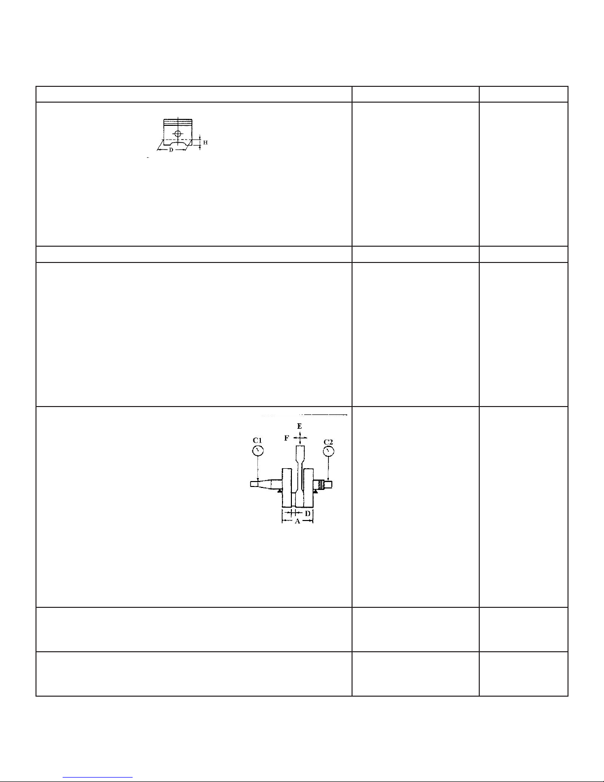
Piston
Piston size “D”
Measuring point “H” (from bottom line of piston lower portion)
Piston offset
Direction of piston offset
Clearance between piston and cylinder
Outside diameter of piston pin
Inside diameter of pin hole
Driving method of balancing block gear driving
Connecting rod of crank
Limit value of runout: C1
C2
Width of crank “A”
Small end free play of connecting rod “F”
Big end free play of connecring rod “D”
Big end radial clearance of connecting rod “E”
Automatic centrifugal clutch
Clutch shoe: quantity
thickness
Clutch messhing revolution
Clutch stalled revolution
Free length of back spring of brake shoe
Clutch:
Action method of clutch
Clutch piece: quantity
thickness
Friction piece: quantity
thickness
Spring of clutch: quantity
free length
Shifting mechanism
shifting method
beding limit of fork guide
Transmission device
offset limit of spindle
offset limit of transmission output shaft
70.92-70.97mm
4.0mm
0.5mm
Inward
0.04-0.006
15.991-16.000mm
16.002-16.013mm
55.95-56.00mm
0.8-1.0mm
0.35-0.65mm
0.010-0.025mm
3 pieces
2.0mm
1800-2100r/min
3200-3600r/min
32.47mm
Outside pushing type
4 pieces
1.45-1.75mm
5 pieces
2.94-3.06mm
4
35.1mm
shift gear cam drunk and
fork 0.8mm
0.15mm
0.03mm
0.06mm
2.0mm
1.5mm
2.8mm
32.9mm
0.08mm
0.08mm
20

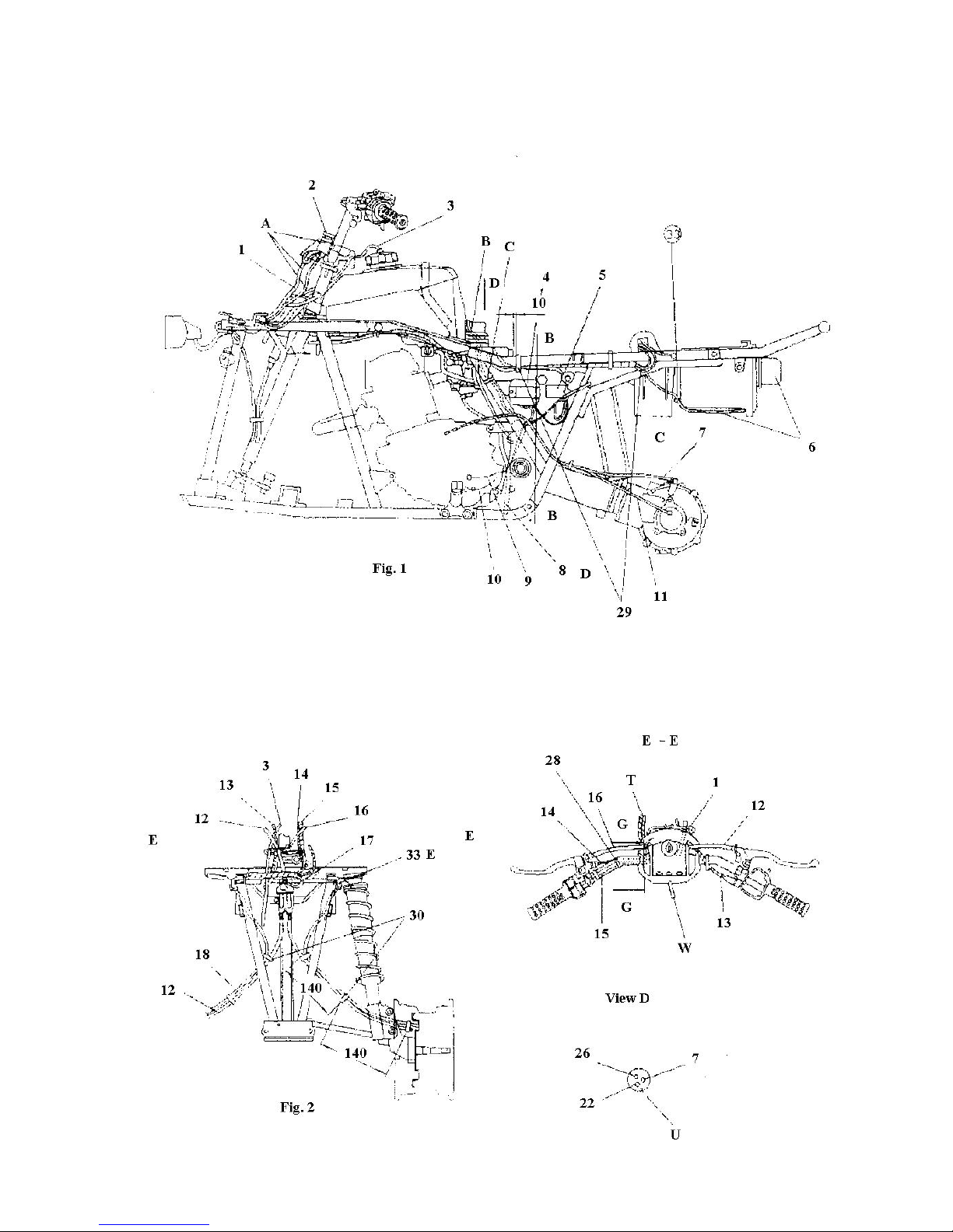
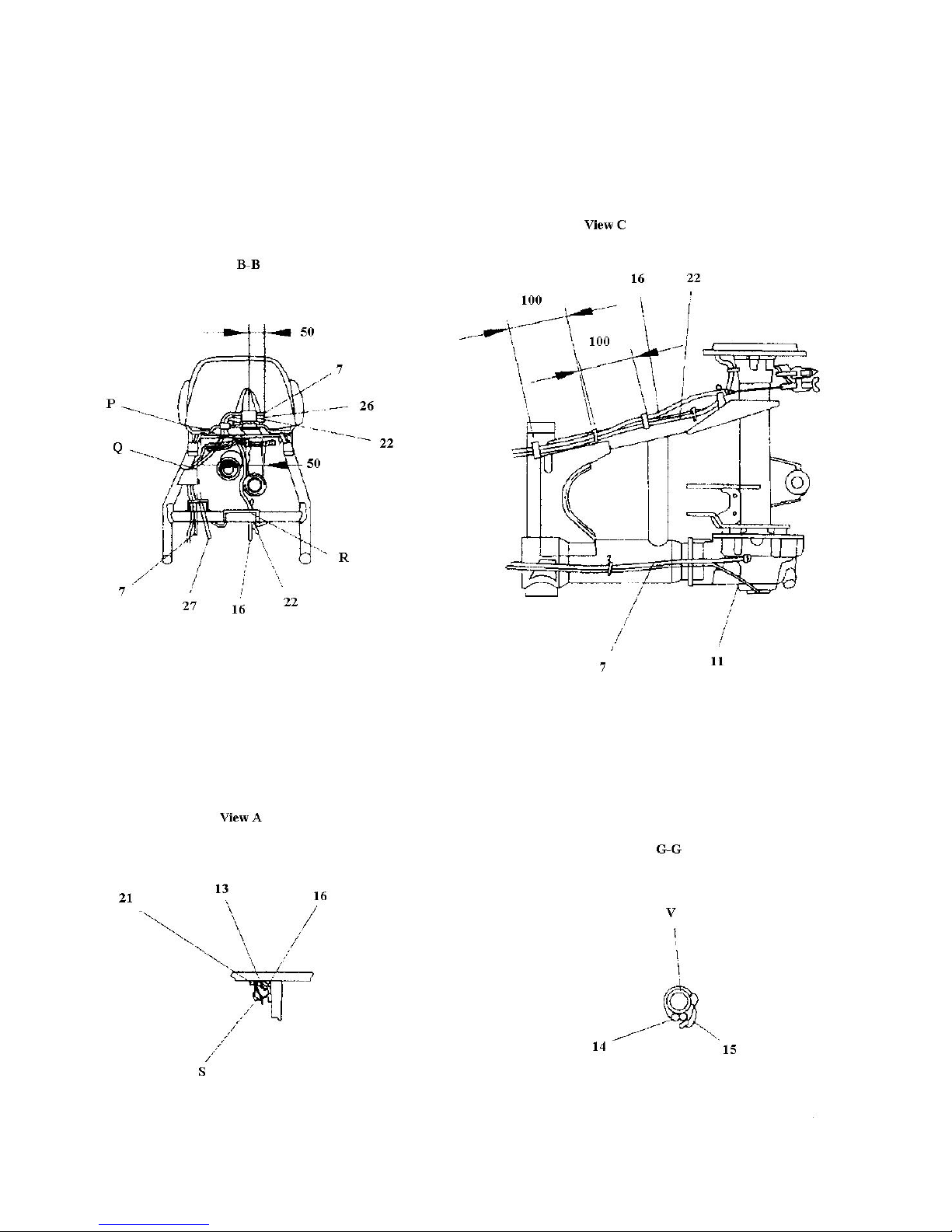
Section6Wiringdiagram
(I) Technical explanation and requirements, details of relative component.
1. Technical explanation
[A] Main switch wire, indicator wire, mileage
meter wire (mounting digital mileage meter)
must be put through the guide grip of holding
seat of steering bar (see gure 1).
[B] Rear brake vent-pipe, carburetor vent-pipe
and vent-pipe of rear driving gearbox must be
inserted into the hole of supporting pad of ventpipe (see gure 1 also see view D).
[C] Neutral and reverse switch wire, mileage
meter wire (moutning with digital mileage meter) should be xed with bands (see gure 1).
[D] After putting overow pipe of carburetor
through two rear xing part of engine (on the
frame) put it ino the proper position between
engine and rear arm. NOTE: overow pipe
must not be blocked (see gure 1).
[S] After putting rear brake cable, throttle
cable, wire of starting motor and mileage meter
(mounting with digital mileage meter) through
wire hook 2, bend wire hook 2 according to the
method of view A.
[P] Starting motor wire and mileage meter wire
(mount with digital mileage meter) must be put
through the hole of the plastic grip in the fuel
tank support of frame (see gure B-B)
[R] Rear brake cable, rear brake vent-pipe
and mileage wire (mount with digital mileage
meter) must be rst put through wire hook 2,
then connect with respective matching unit (see
gure B-B).
[Q] Wire of reverse switch, neutral switch and
mileage meter (mount wih digital mileage meter) must be xed with bands (see gure B-B).
[T] When assembling the wire for ser. No.14
and No.15 do not put through the guide clip of
holding seat of steering bar See gure E-E).
[W] After putting the fuel tank vent tube though
the hole of main switch, lead it to the lower
right side of steering bar, then put it through the
wire hook on the frame. NOTE: Hose must be
unlocked (see gure E-E).
[V] The leading wire on the switch units of
steering bar, must be bound with the band (see
gure G-G).
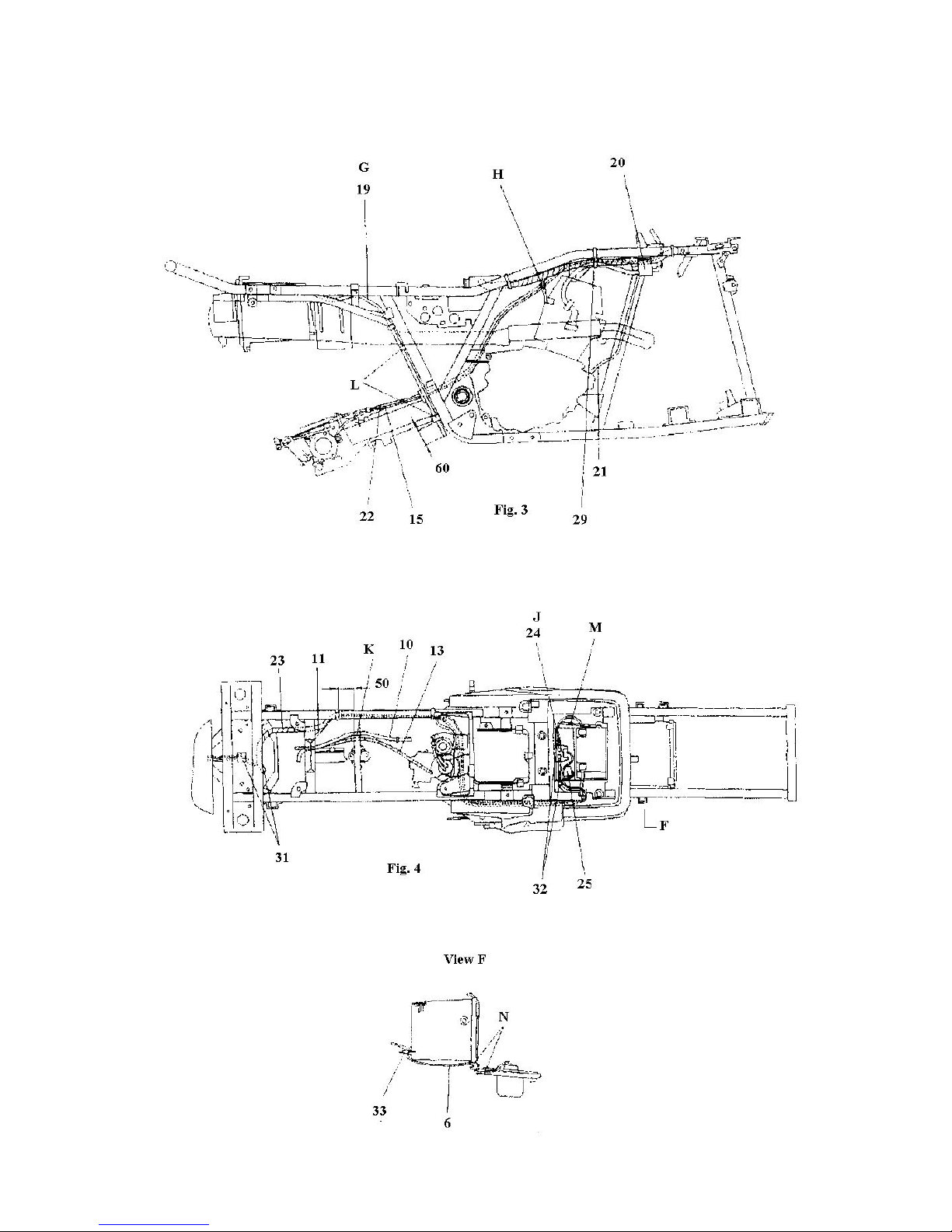
[E] After the vent-tube of the front brake is put
through the plastic clip hole on the frame the
excess should be put in the proper position of
frame (see gure 2).
[G] After the vent-pipe of battery is checked and
free of twists, insert it in the preset hole of rear
fender (If free of maintenance battery is used,
then this item of requirement isn’t needed)
[H] Wire of rear brake cable, rear brake ventpipe and mileage meter (mounted with a digital
mileage meter) should be put through the cable
frame welded on the frame. (see gure3).
[F] Wire of starting motor must be rst put
through the plastic clip on the frame, then connected with the matching units (see gure 3).
[L] Vent-tube of battery should be put through
the plastic clip xed on the frame. (see gure3).
[K] The throttle cable wire, rear brake cable and
mileage meter (mounted using a digital mileage meter) should be pout through the cable
guide frame welded to the frame. (throttle cable
should be mounted on the inner side)
(see gure 4).
[J] Insert the starting relay into the rear fender
(see gure 4).
[M] After putting the vent-tube of battery
through the plastic clip mounted on the rear
fender, insert into the hole on rear fender (combine with G) (see gure [G]) (see gure 4).
21

[U] When assembling, mount supporting pad of
vent-tube should be free of leaks, and pay attention to let the direction of mark upward (see
view D).
[N] Taillight wire must be put through the slot
hole preset by tool kit from the bottom of tool
kit (see view F).
2. Technical requirement
1) In this drawing the wiring condition and position for
all wires are marked. When finished assembling, wiring
should be done as per the drawing.
2) For the wiring and fixing method that cannot be
marked in this drawing, necessary technical explanation
has been made and should be followed.
3. Details of relative component
Ser. #Code Name Qty
33 SSA0-000512-0 Wire clip 4 3
32 SSA0-000511-0 Wire clip 3 2
31 SSA0-000510-0 Wire clip 2 3
30 SSA0-000509-0 Wire clip 1 2
29 JS150.00-039 Cable band 6
28 JS150.00-03 Steering bar band 2
27 C.D.I magneto wire 1
26 Vent tube-carb. 1
25 JS150.00-06 Cut-ff relay 1
24 FG-802000-0 Starting relay 1
23 SSA5-320000-0 Cable 1
22 SSA0-000516-0
21
20
19 Vent tube-battery 1
18 SSA0-000515-0
17 Wire of headlight 1
16 SSA4-230000-0 Rear brake cable 1
15
14 Wire of cltch wire 1
13 SSA4-210000-0 Throttle cable 1
12 SSA4-220000-0
11
10
9
Vent tube-rear brake
Wire of starting motor
High voltage coils and wire
Vent tube-front brake
Wire of handlebar switch
Front brake cable units
Wire of mileage meter
Wire of neutral switch
Wire of reverse switch
1
1
1
1
1
1
1
1
1
8
7 SSA0-000517-0
Overow hose-carb.
Vent tube of gearbox
6 SSA5-630000-0 Taillight unit 1
5 FG-803000-0 C.D.I 1
4 FG-805000-0 Rectier 1
3
Vent tube of gearbox
2 SSA5-510000-0 Main switch lock 1
1 SSA0-012000-0 Wire clip unit 1
22
1
1
1
(II) Wiring diagram (1)
23
(III) Wiring diagram (2)
24
(IV) Wiring diagram (1)
25
Section7Requirementsfortorquefastening
(I) ATV Body
Torque value of fasteners
LockingcomponentandlocationonATV Hard-
ware
Size of
thread
Qty Nm m·kg ft·lb
Front wheel rim & front brake hub Nut M10x1.25 8 55 5.5 40
Front brake hub & steering vertical post Nut M12x1.25 2 25 2.5 18
Front brake cam arm & cam shaft Nut M6x30 2 9 0.9 6.5
Front brake & front shock absorber Bolt M12x50 4 78 7.8 56
Front shock absorber & frame Nut M35x1.5 2 55 5.5 40
Steering veritcal post & pulling rod Nut M12x1.25 2 25 2.5 18
Pulling rod & nut Nut M12x1.25 4 30 3 22
Steering vertical post & end of pulling rod Nut M12x1.25 2 25 2.5 18
Steering vertical post (lower) & frame Nut M10 1 30 3 22
Holding seat of steering vertical post & frame
Steering vertical post & upper/lower holding seat of
steering bar
Bolt M8x60 2 23 2.3 17
Bolt M8x60 4 20 2 14
Front wheel fork & frame Bolt M10x70 4 45 4.5 32
Front wheel fork & brake Nut M12x1.25 2 25 2.5 18
Engine upper connecting plate & frame (upper)
Engine assy & engine upper connecting plate
Bolt M8x16 2 33 3.3 24
Bolt M8x55 1 33 3.3 24
Engine assy & frame (front) Bolt M8x65 1 48 4.8 35
Engine assy & frame (rear upper) Bolt M8x105 1 33 3.3 24
Engine assy & frame (rear lower) Bolt M8x105 1 33 3.3 24
Front fender & frame Bolt M6x16 2 7 0.7 5.1
Front fender ap & front fender supporting rod
Screw M6x16 2 7 0.7 5.1
Bumper & frame Bolt M8x16 4 11 1.1 8
Front luggage carrier & bumper Bolt M6x16 2 11 1.1 8
Front luggage carrier & frame Bolt M8x16 2 34 3.4 25
Front fender & front luggage carrier Bolt M6x20 2 7 0.7 5.1
Rear fender & frame Bolt M6x16 2 7 0.7 5.1
Rear luggage carrier & frame Bolt M6x40 2 7 0.7 5.1
26

(I) ATV Body
Torque value of fasteners
LockingcomponentandlocationonATV Hard-
Size of thread Qty Nm m·kg ft·lb
ware
Rear fender & rear luggage carrier Bolt M8x16 2 7 0.7 5.1
Left & right foot rest & frame Bolt M6x20 4 65 6.5 47
Left & right foot rest & frame Bolt M10x22 2 30 3 22
Supporting weld in foot rest & bracket weld Bolt M8x16 4 30 3 22
Rear rim & hub Nut M10x1.25 8 55 5.5 40
Rear wheel axle & nut Nut M16 2 150 15 110
Rear brake cam arm & cam shaft Nut M6x30 1 9 0.9 6.5
Rear brake show & rear axle housing Bolt M8x1.25 4 28 2.8 20
Rear wheel fork & frame (left) Bolt M22x1.5 1 130 13 94
Rear wheel fork & frame (right)
Rear arm ahst & nut (right)
Bolt M22x1.5 1 6 0.6 4.3
Nut M22x1.5 1 130 13 94
Rear wheel fork unit & rear driving gearbox Nut M10x1.25 4 55 5.5 40
Rear wheel axle bushing & rear driving gearbox
Rear shock absorber (upper) & frame
Bolt M10x1.25x25 4 55 5.5 40
Bolt M12x75 1 50 5 36
Lower cover of gearbox
Bolt M8x12 2 17 1.7 12
Rear wheel axle bushing & rear wheel fork Bolt M12x1.25x25 4 103 10.3 74
Fuel tank & frame Bolt M6x35 2 10 1 7.2
Oil draining bolt of rear driving gearbox Bolt M12x1.25 1 23 2.3 17
Oiling bolt of rear driving gearbox Bolt M12x1.25 1 23 2.3 17
27
(II) Engine
Torque value of fasteners
Lockingcomponentandlocationon
engine
Hardware Size of
thread
Qty Nm m·kg ft·lb Remarks
Observing screw hole of cylinder head cap nut M6 1 7 0.7 5.1
Cylinder head ange bolt M8 4 22 2.2 16 apply oil
to washer
Cylinder head & cylinder Bolt M8 2 22 2.2 26
Sprocket cover Screw M6 2 7 0.7 5.1
Valve cover Bolt M6 5 10 1 7.2
Bearing stop plate of camshaft Bolt M6 2 8 0.8 5.8 apply oil
to washer
Spark plug M12 1 17.5 1.75 12.5
Cylinder Bolt M6 2 10 1 7.2
Balancing shaft gear Nut M14x1.0 1 50 5 36 apply oil
to washer
Starting ratchet disc Bolt M10x1.25 1 50 5 36
Locking nut (adjusting screw of valve clear-
Nut M6 2 14 1.4 10
nace)
Cam timing sprocket Bolt M10 1 60 6 43
Chain tensioner Bolt M6 2 10 1 7.2
Chain tensioner cover Bolt M6 1 7 0.7 5.1
Upper guide plate of chain Bolt M6 2 8 0.8 5.8
Oil pump Screw M6 3 7 0.7 5.1
Oil draining screw plug Plug M35 1 43 4.3 31
Fine lter cover of engine oil (draining oil) Bolt M6 1 10 1 7.2
Fine lter cover of engine oil Bolt M6 2 10 1 7.2
Carburetor seat & cylinder head Bolt M6 2 12 1.2 8.7
Carburetor & carburetor seat Bolt M6 2 12 1.2 8.7
Carburetor & carb. connecting pipe Hose clip M5 1 2 0.2 1.4
Aif lter box & carb. connecting pipe Hose clip M5 1 2 0.2 1.4
Aif lter box & intake pipe Hose clip M5 1 2 0.2 1.4
Silencer & frame Bolt M8 2 34 3.4 25
Silencer & exhaust pipe Bolt M8 1 20 2 1.4
twist w/cable
guide part
28
(II) Engine
Torque value of fasteners
Lockingcomponentandlocationon
engine
Hardware Size of
thread
Qty Nm m·kg ft·lb Remarks
Exhaust pipe Bolt M6 2 10 1 7.2
Crankcase (closing case) Screw M6 11 7 0.7 5.1
Left side cover Screw M6 6 7 0.7 5.1
Left crankcase cover Screw M6 8 7 0.7 5.1
Right crankcase cover Screw M6 9 7 0.7 5.1
Bearing clamp of right crankcase cover Screw M6 3 7 0.7 5.1
Bearing clamp of left crankcase cover Screw M5 3 7 0.7 5.1
Right connecting box Screw M6 3 7 0.7 5.1
Main clutch Nut M22 1 78 7.8 56
Assitant clutch spring Bolt M5 4 6 0.6 4.3
Assitant clutch hub Nut M14 1 50 5 36
Shift cam star-shapped gear Screw M6 1 12 1.2 8.7
Locking nut (clutch releasing adjustable screw) Nut M8 1 15 1.5 11
Starting surpassing clutch Bolt M8 3 30 3 22
Connecting plate of starting motor Screw M6 2 7 0.7 5.1
apply tightening agent
apply tightening agent
Use lock
washer
Use lock
washer
apply tightening agent
Apply tightening agent, rivet
to prevent
lossen
Output gear Nut M16 1 60 6 43
Left case bearing clamp of driving shaft Screw M8 3 25 2.5 18
Rear cover bearing
Reverse gear
inner-hex-
agonal screw
sleeve
Special-shaped
nut (L.H)
2 50 5 36
1 50 5 36
Rear cover Bolt M8 4 23 2.3 17
Front joint Nut M12 1 60 6 43
Reverse gear lever unit Bolt M6 2 12 1.2 8.7
Reverse gear lever unit Bolt M14 1 15 1.5 11
Locking nut of length adjuster of connecting
Nut M8 1 15 1.5 11
rod (reverse gear operation bar assy)
Locking nut of length adjuster of connecting
Nut M8 1 15 1.5 11
rod (reverse gear operation bar assy)
Reverse gear operation rod & reverse gear
Flange nut M6 1 10 1 7.2
lever mechanism
apply tightening agent
apply tightening agent
apply tightening agent
apply tightening agent
29
(II) Engine
Torque value of fasteners
Lockingcomponentandlocationon
engine
Shift pedal Bolt M6 1 10 1.0 7.2
Megneto stator Screw M6 3 7 0.7 5.1
Neutral switch M12 1 20 2.0 14
Reverse gear switch M12 1 20 2.0 14
Hand-started driving disc Screw pin M6 1 12 1.2 8.7
Hardware Size of
thread
Qty Nm m·kg ft·lb
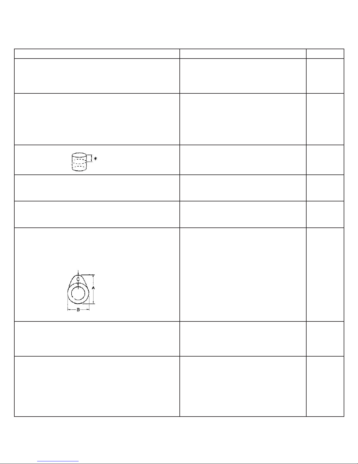
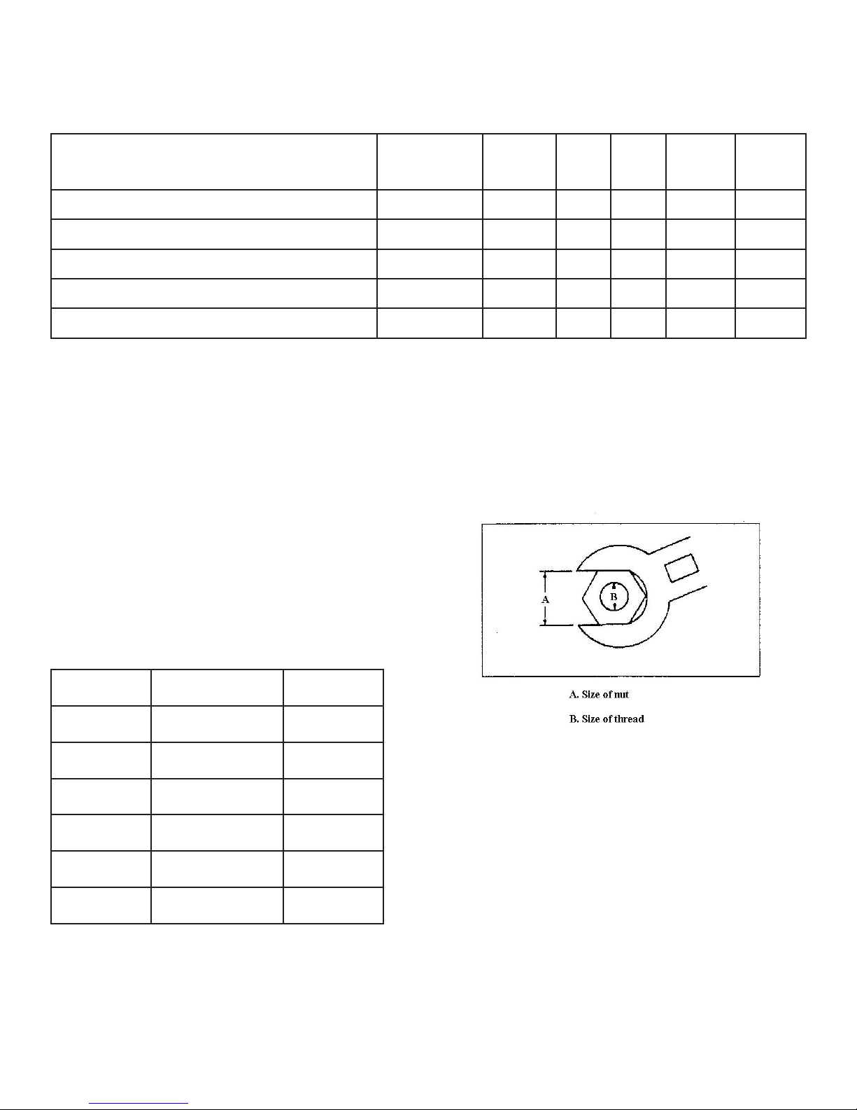
(III) General torque specication
General torque specication (standard screw)
This gure is a screw locking specication
drawn by International Standard Association.
In order to avoid twisting or unbalancing when
locking screw, cross lock as stated below.
* When measuring torque force, standard torque
force testing spanner must be used.
A (Nut) B (Screw) m·kg
10mm 6mm 0.6
12mm 8mm 1.5
14mm 10mm 3.0
17mm 12mm 5.5
19mm 14mm 8.5
22mm 16mm 13.0
30
 Loading...