

Baja Pulsar200 Owner's manual

Pulsar 200
Users Guide
Stern Technologies, Inc.
Raleigh, NC
Phone: (919) 832-8441
Fax: (919) 832-8441 ext 15
Email: info@sterntech.com
Page 1 of 53
Pulsar Users manual.doc

Table of Contents
Description of the Pulsar 200...................................................................................... 4
Glossary...................................................................................................................... 5
Use of the Guide ......................................................................................................... 7
Pulsar Field Updates ................................................................................................... 7
Section I - Checking Out the Pulsar.................................................................................... 8
Unpacking................................................................................................................... 8
Inspection.................................................................................................................... 8
Care and Handling ...................................................................................................... 8
Guaranty...................................................................................................................... 8
Do Not Open the Pulsar Enclosure!............................................................................ 9
Powering on the Pulsar for the First Time .................................................................. 9
Pulsar Power-on Self Tests (POST)........................................................................ 9
Pulsar 200 Generic Display..................................................................................... 9
Checking the Brightness Control ............................................................................ 9
Section II – Operation of the Pulsar 200........................................................................... 10
Design Goals......................................................................................................... 10
Display Screen.......................................................................................................... 10
Gauge Formats .......................................................................................................... 10
Alarms....................................................................................................................... 12
Status Bar .................................................................................................................. 12
Pilot Controls ............................................................................................................ 12
Inputs......................................................................................................................... 13
Data Logging............................................................................................................. 15
Section III – Installation.................................................................................................... 17
IMPORTANT NOTICE............................................................................................ 17
Installation Planning ................................................................................................. 17
Tools and Materials Required................................................................................... 17
Pulsar 200 Panel Mounting....................................................................................... 17
Installing the Exhaust Gas Temperature (EGT) Probes............................................ 19
Installing the Cylinder Head Temperature (CHT) Probes ........................................ 19
Probe Characteristics................................................................................................. 20
Thermocouple Wiring Harness ................................................................................. 20
Installing Sensors ...................................................................................................... 20
Power and Ground Wiring........................................................................................ 20
Routing the Wiring Harness ...................................................................................... 21
Checking the Installation.......................................................................................... 21
Power on Menu......................................................................................................... 21
Diagnostic Screens and Menus ................................................................................. 22
Section IV - Description................................................................................................... 24
Overview................................................................................................................... 24
Description of Pulsar 200...................................................................................... 24
Inputs..................................................................................................................... 25
Operation Mode ........................................................................................................ 27
Display Pages........................................................................................................ 27
Page 2 of 53
Pulsar Users manual.doc

Specifications............................................................................................................ 28
General Specifications .......................................................................................... 28
Technical Specifications ....................................................................................... 29
Section IV – Configuring the Pulsar 200.......................................................................... 31
Configuration Overview ................................................................................................... 31
Methods of Pulsar Configuration.............................................................................. 31
Sensor Overview............................................................................................................... 31
What is a Sensor?.......................................................................................................... 31
What type of Sensors Can the Pulsar Use?................................................................... 32
Configuration Editor......................................................................................................... 33
Pulsar Connection Utility.................................................................................................. 50
Page 3 of 53
Pulsar Users manual.doc

Description of the Pulsar 200
The Pulsar is an electronic data collection and display device designed specifically for
use in experimental aircraft. The Pulsar 200 has a number of inputs specifically
configured for tachometer and thermocouple inputs. The Pulsar 200 also provides 15
configurable general-purpose inputs suitable for monitoring a wide variety of engine
related sensors. The general-purpose Pulsar inputs can also be used to monitoring nonengine related parameters.
The Pulsar is housed in a single module measuring 6.25 ” W x 4.0” H x 3.0” D. The color
liquid crystal display (LCD) measures 4.0” W x 3.0” H and 5.0” diagonally. The Pulsar
will fit into a standard radio stack. The Pulsar faceplate bezel mounts through the front of
the panel.
The Pulsar will work with power inputs ranging from 8 VDC to 28 VDC. Its current draw
is about one amp at 12 VDC with the display at maximum intensity. The Pulsar provides
an input for backup power system. It will detect a failure of the primary power input and
automatically switch to the backup power. The backup power source is external to the
Pulsar.
The user interfaces consists of the 5” diagonal LCD and a single control knob. As show
below in figure 1-1, large digital readouts and color-coded gauges make the Pulsar
display easy to read and comprehend. Control knob is the only input required during
normal operation. This pilot-friendly design allows scanning of monitored parameters
with minimal pilot distraction.
Figure 1-1
Page 4 of 53
Pulsar Users manual.doc

Glossary
Alarm Levels: Alarm levels define the point at which a data value is out of limits. When a data
value is out of limits, it will go into an alarm state. The user can define both minimum and
maximum alarm limits for the Pulsar.
Alarm: The audio and/or visual warnings produced by the Pulsar when a data value is outside of its
defined limits.
Block: During normal operation, the Pulsar display is divided into six equal squares – called blocks.
The user can control the type of information shown in each display block.
Cylinder head temperature (CHT): The temperature, measured by thermocouple, at the top of the
engine cylinder.
Data Logging: Users can selected inputs to monitor and store internally. The Pulsar will place
readings from the selected inputs into a section of memory that is saved even through power on-off
cycles. This section of memory can be downloaded from the Pulsar. The downloaded data is used
for historical analysis of operation.
Display: The Pulsar uses a color video monitor for its display. The Pulsar display can show highresolution graphics and text. During normal operation, the Pulsar display is divide d into six equal
blocks.
Download and Downloading: Downloading is the transfer of electronic information from one
computing device to another.
Engine parameter: An engine parameter is any engine data monitored by the Pulsar. A parameter
may be a directly monitored value, such as oil temperature. An engine parameter may also be a
calculated value, such as the EGT span – the difference from the highest to lowest EGT reading.
Exhaust gas temperature (EGT): The temperature, as measure by thermocouple, at the immediate
outlet of each cylinder’s exhaust port.
Fuel totalizer: A summary status of important fuel system information. The fuel totalizer reports on
fuel flow, fuel pressure, fuel used, fuel remaining (volume) and flight time to empty.
Inputs: External electrical signals brought into the Pulsar on its back panel pins. The external
electrical signals are typically from sensors.
Liquid crystal display (LCD) The Pulsar display is a liquid crystal display (LCD). Modern LCD
technology allows the use of displays that are compact, rugged and low power while still producing
high brightness and full color.
Page: The user can control the Pulsar display to show different views of monitored data. The
control knob switches from one view of display data to the next. Each unique screen of the display
with its associated gauges and data represents a Page.
Range: The span from a gauge’s minimum value to its maximum value is its range. A temperature
gauge that displays from 100 to 250 ºF has a range of 150 ºF.
Red line: Indicates the danger zone alarm for a data value.
Sensors: Sensors are devices for converting physical properties (such as pressure, temperature and
flow) into electrical signals. The Pulsar can then read these electrical signals.
Set Up: The initial steps required to prepare the Pulsar for operation. Set up steps may include
setting Pulsar alarm limits or customizing the display.
Page 5 of 53
Pulsar Users manual.doc

Thermistor: A temperature sensor that changes its resistance in response to a change in
temperature. Thermistors are typically used for measuring lower temperatures (up to 200 °F).
Thermocouple: A temperature sensor constructed by welding two wires of different metal alloys
into a junction. A temperature difference between the bi-metallic junction and a remote section of
the wires will produce a very small voltage differential. For different combinations of metals linear
voltage vs. temperature charts can be produced. Thermocouples are used for measuring high
temperatures (up to several thousand degrees Fahrenheit).
Yellow line: Indicates the warning or caution zone alarm for a data value.
Page 6 of 53
Pulsar Users manual.doc

Use of the Guide
The Pulsar Basic User’s Guide is divided into six sections.
Section I – Checking out the Pulsar 200 describes the initial preparation and handling
steps.
Section II – Operation of the Pulsar 200 describes the operation of the unit including
inputs, outputs, the display, pilot controls and data logging.
Section III - Installation covers the mounting of the unit, sensor installation, and wiring
connections.
Section IV – Description shows how to download the Pulsar 200 customization software
from the supplied CD-ROM to your PC.
Section V – Configuring the Pulsar 200 describes the procedure for basic customization
of the software for your Pulsar 200.
Section VI – Specifications provides detailed electrical and mechanical specifications for
the Pulsar 200 and other useful information.
The basic software configuration has many present selections. For complete
customization of all the configurations of the Pulsar 200 refer to the Pulsar 200 Advanced
User’s Guide.
Pulsar Field Updates
From time to time Stern Technologies will provide updates for the Pulsar. These updates
may add new features or correct reported problems. The field updates will change the
program memory resident on the Pulsar. Field update distribution will be via CD-ROM or
from the Stern Technologies web site.
Field updates must be downloaded to the Pulsar using the front panel serial port and a
PC. Windows application documentation provides detailed instructions for performing
Pulsar field updates.
Page 7 of 53
Pulsar Users manual.doc

SECTION I - CHECKING OUT THE PULSAR
Unpacking
Unpack the Pulsar and verify that you have received the following materials:
? Pulsar 200
? Packing list and/or detail receipt
? Connector/harness kit (contents will vary depending on order - see packing list for
specific items delivered)
? Sensor package (contents will vary depending on order – see packing list for
specific items delivered)
? Pulsar 200 User’s Guide
? AC power adapter
? *Pulsar 200 Configuration CD-ROM
? *Serial data cable (3.5mm audio jack to 9-pin DB)
* - Optional material for PC-based customization of the Pulsar.
Inspection
? Carefully inspect the contents of this package for damage. If damage is found, save all
packaging for carrier insurance claims.
? Inspect the contents of the shipment to ensure receipt of all component parts and
materials.
? Visually inspect all components for proper identification or damage. Report any
discrepancies to Stern Technologies within 15 days.
Care and Handling
The Pulsar can withstand rugged use. However, standard precautions for electronic
equipment are required:
? Do not expose to rain or water
? Handle with care – do not drop
? Be sure that all electrical connections are correct and properly made
? The Pulsar display may be cleaned with a soft cloth and mild non-abrasive
cleaning solution
? If the display cracks, it is possible for the liquid crystal to escape from the panel.
Use soap and immediately wash any contact with the liquid crystal.
Guaranty
Stern Technologies provides a 60-day money back guaranty on all its products. This
provides you with ample time to determine that you are pleased with your purchase. If at
any time during this 60-day period you determine that you would like to return the
product please contact Stern Technologies customer support department for a return
Page 8 of 53
Pulsar Users manual.doc

material authorization (RMA) number. Do not return material to Stern Technologies
without first obtaining an RMA number.
Stern Technologies will not charge a restock fee for equipment returned complete and
undamaged during the initial 60-day evaluation period.
Do Not Open the Pulsar Enclosure!
There are no user serviceable parts or adjustments inside the Pulsar. Opening the Pulsar
enclose will break the internal safety seals and VO ID your warranty and guaranty.
Powering on the Pulsar for the First Time
Connect the supplied AC voltage adapter to the Pulsar rear panel connector J1 (six pin
connector). The connector on the AC voltage adapter is keyed and cannot be inserted
incorrectly. Plug the AC voltage adapter into a convenient AC outlet.
Pulsar Power -on Self Tests (POST)
? When powered on the Pulsar will test its internal memory and processors. A screen
message will briefly display the results of the power-on self-test (POST).
? After a successful completion of the POST the Pulsar will proceed to normal operation
mode.
? If any errors are detected during the POST the Pulsar will attempt to repair the errors
and will inform the user. Note if errors keep reoccurring you should contact Stern
Technologies as soon as possible.
Pulsar 200 Generic Display
? The Pulsar 200 ships with generic software loaded. After a successful power-on, the
first page of the generic display is shown. Rotate the control knob clockwise to
change display pages.
? Rotate the control knob counter-clockwise to return to the first display page. When the
display stops changing, you have scrolled through to the first (turning counterclockwise) or the last (turning clockwise) page in the display.
Checking the Brightness Control
? The control knob on the front panel adjusts display brightness when the knob is
pushed in and turned.
? Turning counter clockwise dims the display. If the knob continues to be rotated in the
counter-clockwise direction (while being pushed in) the background will change to
black for low light viewing.
Page 9 of 53
Pulsar Users manual.doc

SECTION II – OPERATION OF THE PULSAR 200
Design Goals
The major design goals for the Pulsar 200 are:
? To present many engine parameters in an easy to comprehend format
? To make selections of engine data simple and easy
? To provide the aircraft owner with an extremely flexible customization of all the
Pulsar’s operating characteristics (displays, inputs selections, special functions,
parameter ranges and alarm levels)
Display Screen
? The five-inch diagonal color screen presents sensor data from 36 inputs (such as
cylinder head temperatures) as well as calculated data (such as rate of change of
cylinder head temperature)
? Up to ten different display pages can be assessed during normal operation. Each page
has six individual blocks – two rows of three columns. Each block can be set to
display one or multiple gauge formats.
? The control knob is used to scroll between display pages.
Figure 2-1: Pulsar display screen
Gauge Formats
Each display page block can be set to display one or multiple gauge formats. Five
different types of gauge formats are available: four types of analog gauges and one type
of text gauge. The gauge format selected will depend on the parameter or parameters to
be displayed and the preference of the user. The five gauge formats are shown below:
Some of the gauges include special features. The multi-bar gauge indicates which of the
parameters shown has the highest value (up pointer) and which has the lowest value
(down pointer).
Page 10 of 53
Pulsar Users manual.doc
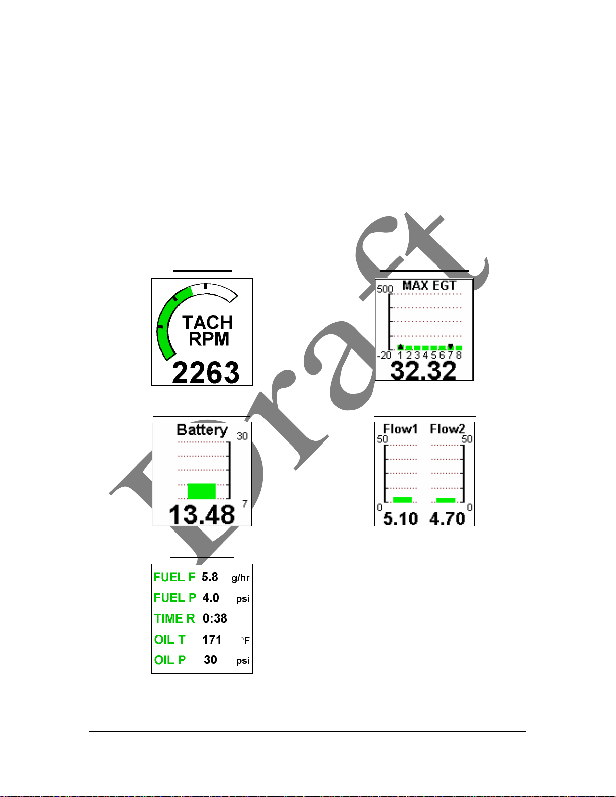
The user can configure text gauges to display up to five parameters in one block. For
diagnostic purposes, an entire page can be devoted to text gauges. This allows
simultaneous viewing and comparison up to 30 parameters.
The user can also set the range of a gauge. For example, the RPM range might be set
from 0 to 3000 RPM for a Lycoming engine – or it could be set from 0 to 3500 for a
Jabiru engine.
The user sets the alarm limits separately from the gauge displays. Alarms can be set for
minimum and maximum values. Alarm limits can be set to indicate a warning range
(yellow) and a danger range (red).
Figure 2-2: Gauge Formats
Arc gauge Multi-bar gauge
Single bar gauge Double bar gauge
Text gauge
Page 11 of 53
Pulsar Users manual.doc

Alarms
The user can configure different alarm levels on the Pulsar. A warning level alarm
(normally indicated with a yellow color) tells the pilot a parameter is about to enter a
dangerous level. A danger level alarm (normally indicated with a red color) tells the pilot
a parameter has entered the danger zone.
The Pulsar provides both audio and visual indications for alarms. If the audio alarm pins
on the J1 connector are attached to an audio device (such as an intercom), a tone will be
generated when an alarm is active. In addition, the gauge containing the out-of -level
parameter will be display in its alarm color (yellow or red – depending on the alarm
level) and begin to blink.
The pilot can acknowledge this alarm by pushing in the control knob. The audio alarm
and display blinking will stop. The gauge will remain in its alarm color as long as the
value of the parameter stays in the alarm range. An alarm status indicator will also appear
in a status area at the bottom of the display. The alarm status will always be display, even
if the pilot switches pages.
If the parameter remains at the danger alarm level (red), the alarm sequence (audio and
display blinking) will reoccur every 5 minutes to remind the pilot of the alarmed
parameter. The user can modify this interval if desired.
Status Bar
A status bar is placed at the bottom of each page and is the same for all pages. The status
bar includes the date and time and indicates if any parameters are in an alarm condition.
If multiple parameters are in an a larm condition, only one alarm is shown.
The time display is in 24-hour format. The user can set both date and time. The format
for the date and time display is:
MM/DD/YYYY HH/MM/SS
Pilot Controls
A single knob on the front panel provides the pilot with three functions during normal
operation.
1. Page Selection – Turning the control knob scrolls the display pages. Turning the
knob counter clockwise will scroll up toward the first page. Turning the knob
clockwise will scroll down toward the last page. Scrolling will stop when the
reaching the first or last page .
2. Acknowledge – The pilot acknowledges warnings and alarms by pushing in the
control knob.
3. Screen brightness – The pilot can push in and turn the control knob to adjust the
screen brightness. Turning counter clockwise will dim the screen while turning
clockwise will brighten the screen. As the screen dims, the screen contrast will
Page 12 of 53
Pulsar Users manual.doc

change from dark characters on a light background to light characters on a dark
background.
The control knob is a lso used for various selections when the Pulsar is in menu mode.
Inputs
The Pulsar directly monitors 36 inputs. In many applications, not all of the inputs are
used.
Some Pulsar inputs work with specific types of signals such as thermocouple voltages or
the signals from magneto P leads. The configurable inputs can handle signals from a
variety of sender types.
Page 13 of 53
Pulsar Users manual.doc

Table 2-1: Pulsar Inputs
Input Connector Pins Input Type
J2-9 (-), J2-10 (+) thermocouple
J2-11 (-), J2-12 (+) thermocouple
J2-13 (-), J2-14 (+) thermocouple
J2-15 (-), J2-16 (+) thermocouple
J3-9 (-), J3-10 (+) thermocouple
J3-11 (-), J3-12 (+) thermocouple
J3-13 (-), J3- (+) thermocouple
J3-15 (-), J3-8 (+) thermocouple
J2-1 (-), J2-2 (+) thermocouple
J2-3 (-), J2-4 (+) thermocouple
J2-5 (-), J2-6 (+) thermocouple
J2-7 (-), J2-8 (+) thermocouple
J3-1 (-), J3-2 (+) thermocouple
J3-3 (-), J3-4 (+) thermocouple
J3-5 (-), J3-6 (+) thermocouple
J3-7 (-), J3-8 (+) Thermocouple
J4-15 (+), J4-16 (-) Inductive input
J5-1 AC voltage (coil, magne to, alternator)
J4-1 AC voltage (coil, magneto, alternator)
J5-15 Configurable
J4-11 Configurable
J5-13 Configurable
J5-14 Configurable
J5-11 Configurable
J5-12 Configurable
J5-6 Configurable
J4-6 Configurable
J5-3 Configurable
J4-3 Configurable
J5-9 Configurable
J4-9 Configurable
J4-14 Configurable
J4-13 Configurable
J4-12 Configurable
J1-1 (+), J1-2 (-) Voltage
J1-3 (+), J1-4 (-) Voltage
J1-6(+), J1-5(-) Alarm Output
Configurable inputs will accurately measure resistive, voltage or frequency output
senders.
? The input range for resistive senders is from 10 ohms to 12,000 ohms
? The input range for voltage senders is from 0.4V DC to 4.5V DC
? The input range for frequency senders is 5 Hz to 10,000 Hz.
? The input range for coil inputs is 0 Hz to 500 Hz.
Page 14 of 53
Pulsar Users manual.doc
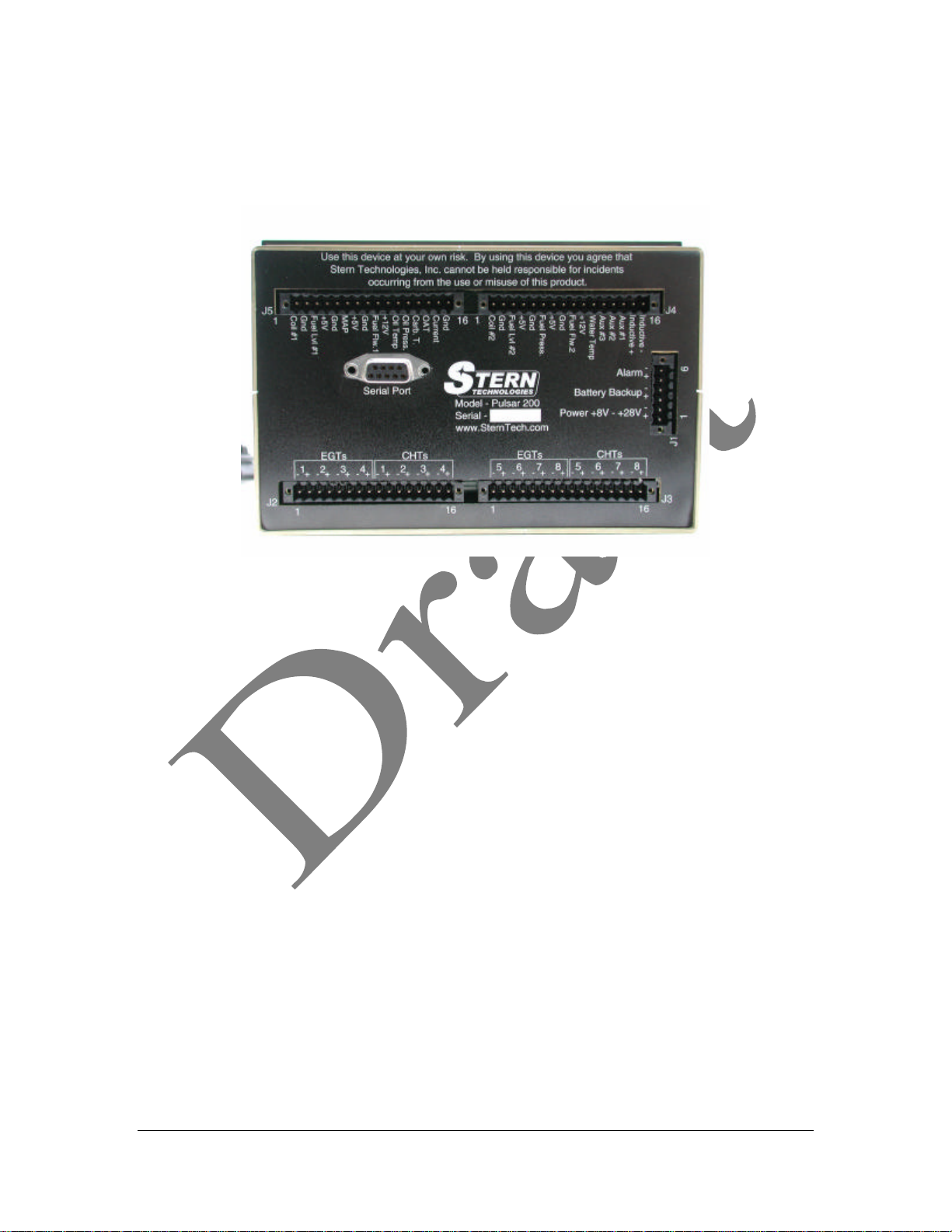
Figure 2-4 shows the rear panel connections for the Pulsar. J1 through J5 are printed
circuit board mounted connectors. Sensor inputs are terminated to cable plugs with a
screw down latch. These connections are gas tight and provide long-term reliability.
Figure 2-4: Pulsar Rear Panel Connections
Data Logging
The Pulsar 200 provides a data logging capability. The user determines the parameters to
log and the rate of data logging ( the maximum data logging rate is 10 samples per
second). The depth of data logging (number of hours that can be record) is determined
by:
1. the number of parameters logged, and
2. the frequency of data logging
Logging twelve parameters (for example: 4 EGT’s, 4 CHT’s, tachometer, oil pressure, oil
temperature and fuel flow) at a sample rate of once per second (all parameters record
each second) will provide approximately 100 hours of data recording time. Each sample
includes a time and date stamp.
Users retrieve logged data from the Pulsar front panel serial port. A PC is required to
download data from the Pulsar. Downloaded data can be directly imported into a number
of computer programs for analysis or graphing. Figure 2-5 shows data logged by the
Pulsar and graphed in a Microsoft Excel spreadsheet. Chapter xx provides details on data
logging, downloading and analysis.
Page 15 of 53
Pulsar Users manual.doc
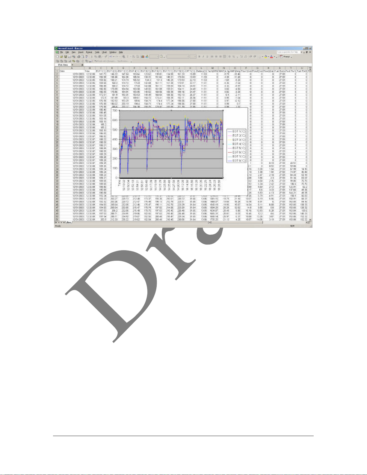
Figure 2-5: Logged Pulsar data graphed in an Excel spreadsheet
Page 16 of 53
Pulsar Users manual.doc
 Loading...