

Baja BLASTER 6.5 Setup Instructions

BAJA BLASTER 6.5 SET UP INSTRUCTIONS
1. Remove cardboard carton from
metal frame
2. Remove operating instructions
and owners manual located on top of
Go-Kart.
3. Remove hardware box
4. Remove bolts as indicated in photo
from both sides of metal frame
5. Carefully remove metal
frame
E - REV - A
1
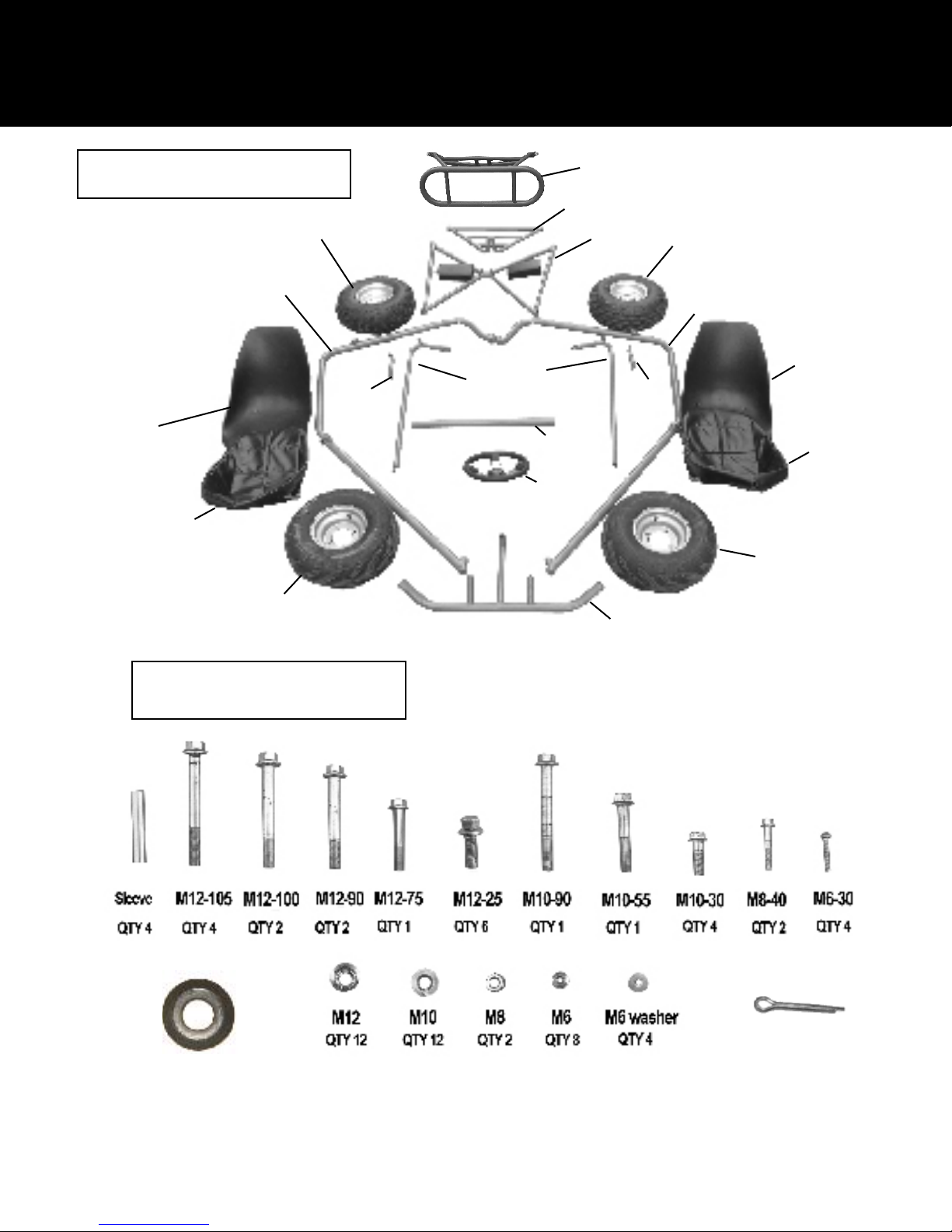
Parts and Hardware
6. Remove parts from crate, layout
according to diagram
Rear tire
Right Brush
Guard
Seat
Seat cover
Nerf
Brace
Left and
right Nerf
Bars
Cross Support
steering
wheel
Rear bumper
Rear Rack
Cross braces
Nerf
Brace
Rear Tire
Left Brush
Guard
Seat
Seat cover
Front tire
Front Tire
7. Remove parts from hardware box
and layout accordingly.
Rubber Grommets
QTY 8
Front bumper
Cotter Pin
QTY 2
2
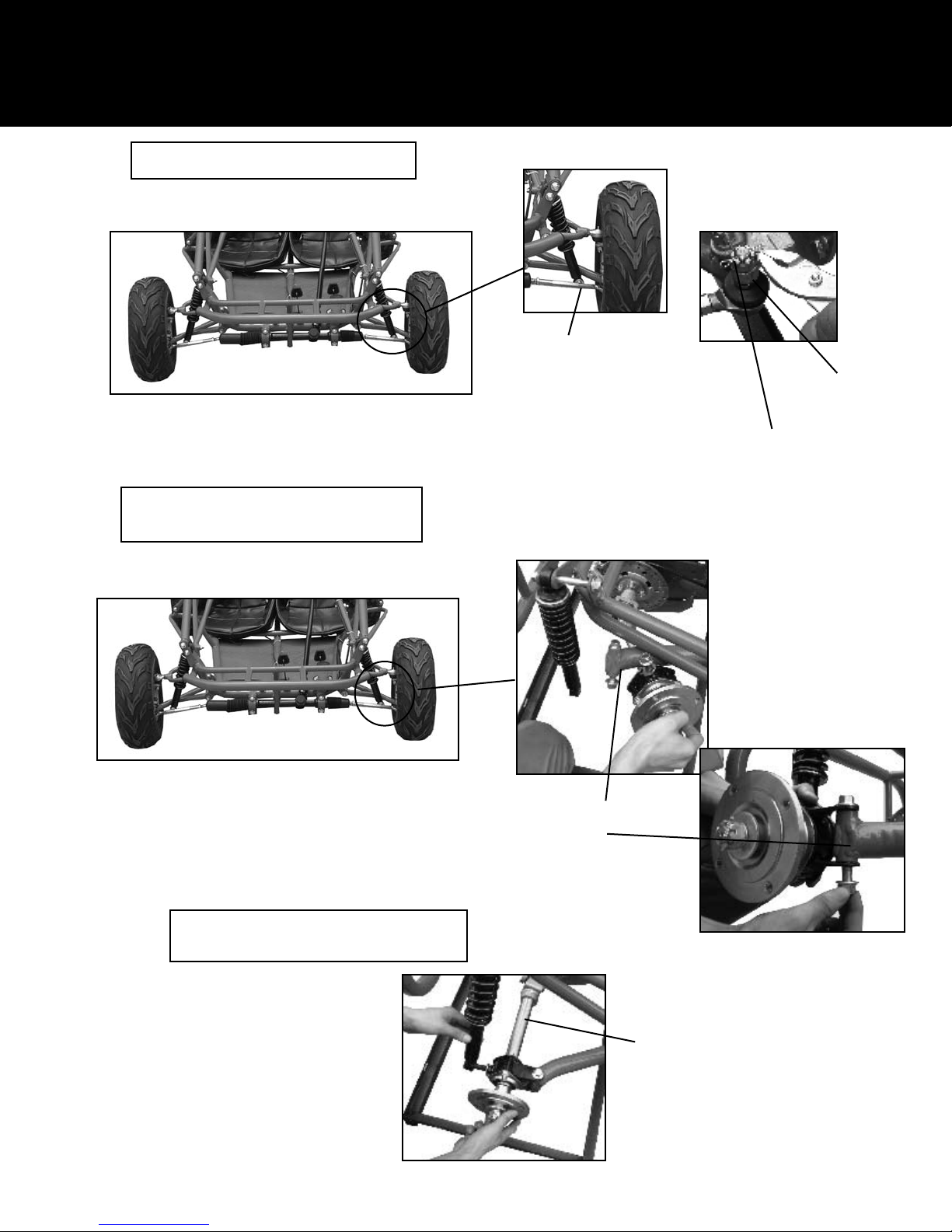
Tie Rod and Rear Shock Assembly
8. Attach Tie rod to spindle assembly
Tie Rod
9. To attach rear axle to support bar you
must rst remove the rear bumper
Castle nut
Cotter pin
NOTE: The rear guard has been removed to show
detail.This assembly must be performed with
removing the rear guard.
10. Attach rear shock to axle using
bolt and nut already attached to shock.
Trailing arm axle support
Axle
3
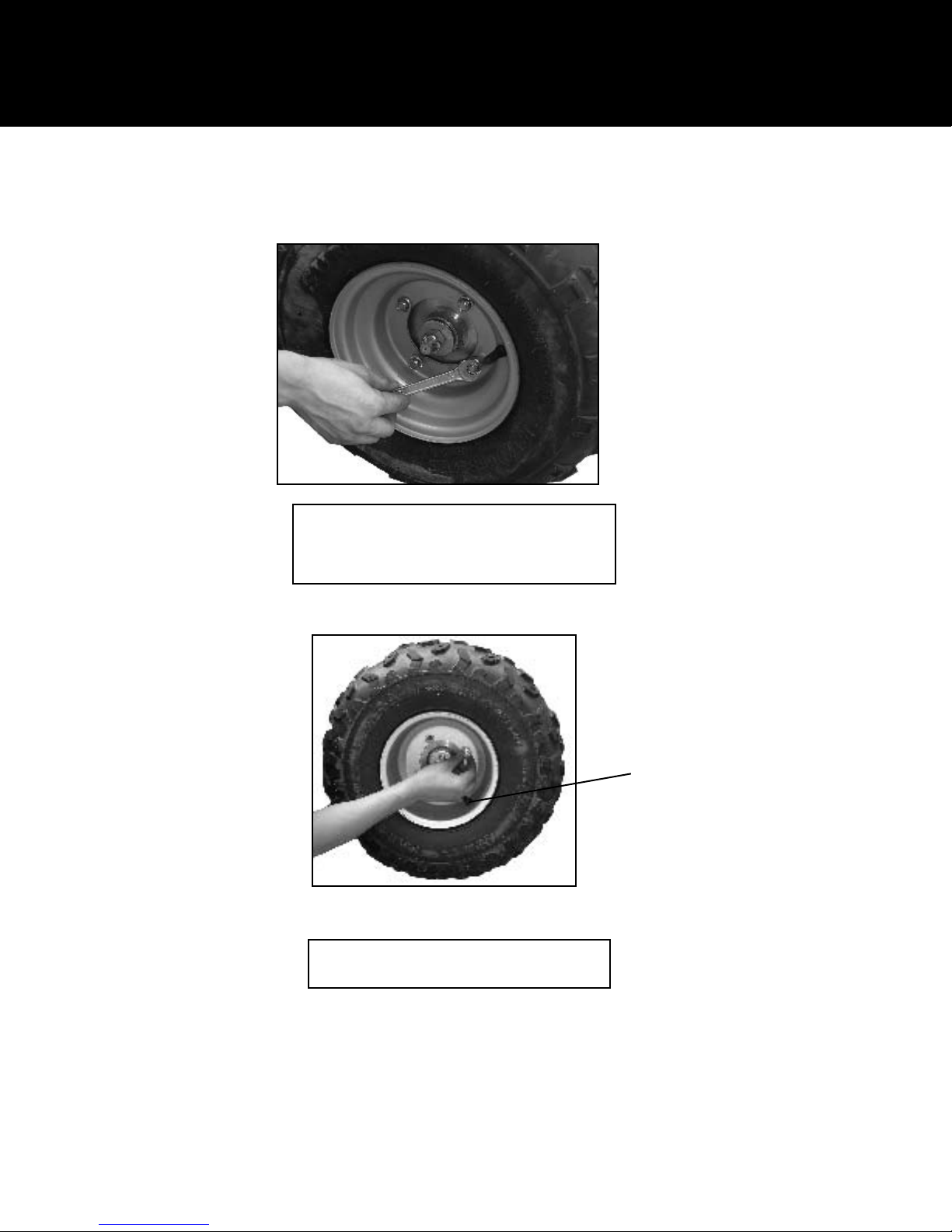
Front and Rear Wheel Assembly
NOTE: The front rim is not as “Deep” as the rear
rim on the side containing the air ll valve.
11. Attach front wheels using 4 M10 nuts
Torque lug nuts to 33ft.lbs. Make sure the
air ll valve is facing out.
12. Attach rear wheels using M10 nuts.
Torque lug nuts to 33ft. lbs.
4
The rear wheels have “Deeper” rims
on the side with the air ll valve.
 Loading...