

Page 1
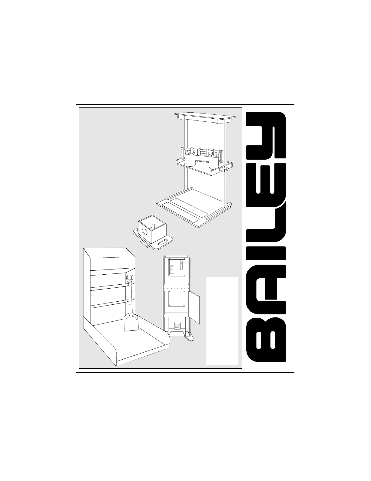
6000 Series
Work Simulation Devices
Product Manual
Covers
Models:
6030
6031
6044
6045
6046
6047
6048
6049
BAILEY MANUFACTURING COMPANY
800-321-8372 • FAX: 800-224-5390
C0914
Mail: P.O. Box 130, Lodi, OH 44254-0130
Shipments: 118 Lee St., Lodi, OH 44254
Page 2

Important
Read This First
Bailey Manufacturing Company is proud of the
reputation we have earned as a leader in the
physical, occupational, and sports medicine industry
for more than 50 years. Our products are made
from the highest quality materials and built in the USA
by skilled craftsmen.
Prior to shipping, this product was thoroughly
inspected to ensure the highest quality standards and
your total satisfaction. If you experience any
problems, please follow the instructions outlined in
the Warranty & Support Section of this manual.
Contact either your dealer or Bailey at 1-800-321-
8372.
Please take a moment now and record the following
information for future reference:
Date of Purchase [delivery date]:
Bailey Dealer:
Packing Slip #:
Serial Number:
Date of Manufacture:
Model Number:
Page 3

6000 Series Work Simulation Devices Page 3
Contents: Pages:
Product Section 4 thru 18
General Information 4
Parts 4 - 7
Assembly 7 - 13
Operation 14 -17
Safety 17
Maintenance & Cleaning 18
Troubleshooting 18
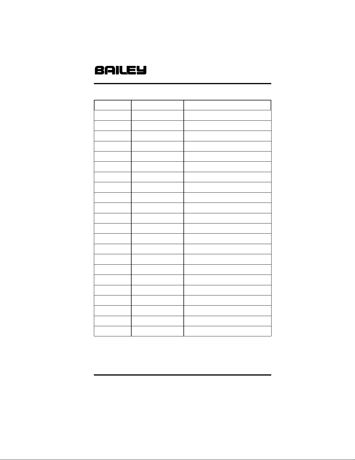
Inspection & Service Logsheet 23
Warranty & Support Section 19 thru 22
Warranty Terms 19
Product Support & Assistance 20
Product Registration 21
Damage & Loss In Transit 21
Returns 22
BAILEY MANUFACTURING COMPANY
800-321-8372 • FAX: 800-224-5390
Page 4

Page 4 6000 Series Work Simulation Devices
General Information:
Read entire Product Manual before assembling and using
this product. If you have any questions regarding the
following information, please contact a Bailey Customer
Service Representative at 1-800-321-8372.
Features & Specifications, Model 6030:
• Removable weight holder with weight keeper.
• Variety of fasteners included.
• Maximum load capacity of 80 lb. / 36 Kg.
Features & Specifications, Model 6031:
• Convenient wall mount with height adjustment.
• Variety of fasteners included.
• Mounting hardware not included.
Features & Specifications, Model 6044:
• Composed of 102 individual parts [including supplied
hardware] for hand assembly simulation.
• Includes Hex Key tool.
Features & Specifications, Model 6045:
• Three (3) angled shelves at multiple heights.
• Shovel included.
• Recommended work material is SAND [not included].
Features & Specifications, Models 6046 & 6047:
• Basic electrical assembly supplies included.
• Not to be wired with live current [see Safety section].
Features & Specifications, Model 6048:
• Sorting bins with adjustable upper separators.
• Six (6) assorted fixed lower sorting bins.
Features & Specifications, Model 6049:
• Eight (8) position adjustable [6” increments] height shelf.
• Fixed postion upper shelf.
• Maximum load capacity 80 lb. / 36 Kg.
Parts:
Your new Work Simulation Device is shipped “knocked
down”, with all hardware and parts included for final
assembly. Models 6030, 6044 & 6046 are shipped fully
assembled and ready to use.
BAILEY MANUFACTURING COMPANY
800-321-8372 • FAX: 800-224-5390
Page 5

6000 Series Work Simulation Devices Page 5
Parts [cont’d]:
Inspect the unit carefully, immediately upon removal from
packaging, to ensure that the unit is in good condition and all
materials are present before starting assembly.
Note: Bailey Manufacturing Company waives any
responsibility for concealed freight damage not reported
within five (5) days of receiving shipment. Refer to Product
Warranty and Support Section of this Manual for more
information.
The following parts are supplied with these Models:
Model 6030 Lifting/Bolt Center:
• (1) EA. #A6020WH, Removable 6 1/2” Weight Holder
• (1) EA. #19250 Weight Keeper
• (10) EA. #1408 3/8-16 x 1 1/2” Hex Head Screw
• (5) EA. #2560 3/8-16 Hex Nut
• (20) EA. #3610 3/8 SAE Flatwasher
• (5) EA. #2630 3/8-16 Wing Nut
Model 6031 Work Station:
• (1) EA. #21443 3/8-16 x 1/2” Male Height Adjust Knob
• (2) EA. #16050 1/2-13 Female Round Knob
• (2) EA. #21426 3/8-16 Female Ball Knob
• (2) EA. Snap-on Finger Strap
• (12) EA. # 1408 3/8-16 x 1 1/2” Hex Head Screw
• (2) EA. #1503 1/2-13 x 1 1/4” Hex Head Screw
• (5) EA. #2560 3/8-16 Hex Nut
• (5) EA. #2630 3/8-16 Wing Nut
• (1) EA. #3425 3/8-16 x 3/8” Socket Set Screw
• (1) EA. # 3450 3/16” Hex Key
• (20) EA. #3610 3/8 SAE Flatwasher
Model 6044 Hand Assembly Device:
• (2) EA. Shaft
• (22) EA. #15151 Shaft Collar with Setscrew
• (4) EA. #1290 1/4-20 x 2 1/4” Hex Head Screw
• (4) EA. #1291 1/4-20 x 2 1/4” Slotted Head Screw
• (4) EA. # 1420 3/8-16 x 2 1/4” Hex Head Screw
• (4) EA. #2540 1/4-20 Hex Nut
[continued on page 6]
BAILEY MANUFACTURING COMPANY
800-321-8372 • FAX: 800-224-5390
Page 6

Page 6 6000 Series Work Simulation Devices
Parts [cont’d from page 5]:
Model 6044 Hand Assembly Device [Cont’d]:
• (4) EA. #2610 1/4-20 Wing Nut
• (4) EA. #2560 3/8-16 Hex Nut
• (1) EA. #3451 5/32 Hex Key
• (16) EA. #3581 1/4” SAE Flatwasher
• (8) EA. #3610 3/8” SAE Flatwasher
Model 6045 Shoveling Station:
• (8) EA. #2300 3/8-16 x 2” Carriage Bolt
• (8) EA. #2560 3/8-16 Hex Nut
• (8) EA. #3597 3/8 Lockwasher
• (8) EA. #3610 3/8 SAE Flatwasher
• (1) EA. #16212 Shovel
Model 6046 Tabletop Electrical Assembly Center:
• (12) EA. #15255 Twist-on Wire Connector
• (6) EA. #15256 Conduit Fitting
• (24) EA. #15257 Crimp-on Lug Terminal
• (20) FT. #15258 14 AWG Wire, White
• (20) FT. #15259 14 AWG Wire, Green
• (20) FT. #15260 14 AWG Wire, Red
Model 6047 Deluxe Electrical Assembly Center:
• (2) EA. Cabinet Support
• (4) EA. #1275 1/4-20 x 1” Hex Head Screw
• (4) EA. #3581 1/4” SAE Flatwasher
• (24) EA. #15255 Twist-on Wire Connector
• (12) EA. #15256 Conduit Fitting
• (24) EA. #15257 Crimp-on Lug Terminal
• (20) FT. #15258 14 AWG Wire, White
• (20) FT. #15259 14 AWG Wire, Green
• (20) FT. #15260 14 AWG Wire, Red
Model 6048 Sorting Bin:
• (4) EA. Upper Bin Divider
Model 6049 Adjustable Height Shelf:
• (1) EA. Base Assembly
• (2) EA. Upright Support Tube
• (1) EA. Adjustable Shelf Assembly
• (1) EA. Top Shelf Assembly
BAILEY MANUFACTURING COMPANY
800-321-8372 • FAX: 800-224-5390
Page 7

6000 Series Work Simulation Devices Page 7
Parts [Cont’d]:
Model 6049 Adjustable Height Shelf:
• (4) EA. #1405 3/8-16 x 1 1/4” Hex Head Screw
• (4) EA. #1420 3/8-16 x 2 1/2” Hex Head Screw
• (4) EA. #2560 3/8-16 Hex Nut
• (12) EA. #3597 3/8 Lockwasher
• (4) EA. #3610 3/8 SAE Flatwasher
• (2) EA. #15031 Plunger Assembly
Assembly:
The following Work Simulation Devices are shipped fully
assembled and need no assembly or installation:
• Model 6030 Lifting/Bolt Center
• Model 6044 Hand Assembly Device
• Model 6046 Tabletop Electrical Assembly Center
For all “knocked down” devices, the following minimum tools
are required:
• 7/16” wrench
• 9/16” wrench
Any of these additional tools will make assembly easier:
• 7/16” socket and drive ratchet
• 9/16” socket and drive ratchet
Model 6031 Wall Installation:
Note: Due to wide variances in wall and building
construction, no mounting hardware or detailed
hardware recommendations are provided. Consult an
installation contractor or design professional who is
familiar with your particular wall construction and
materials. They can ensure compliance with the Uniform
Building Code and any applicable local codes.
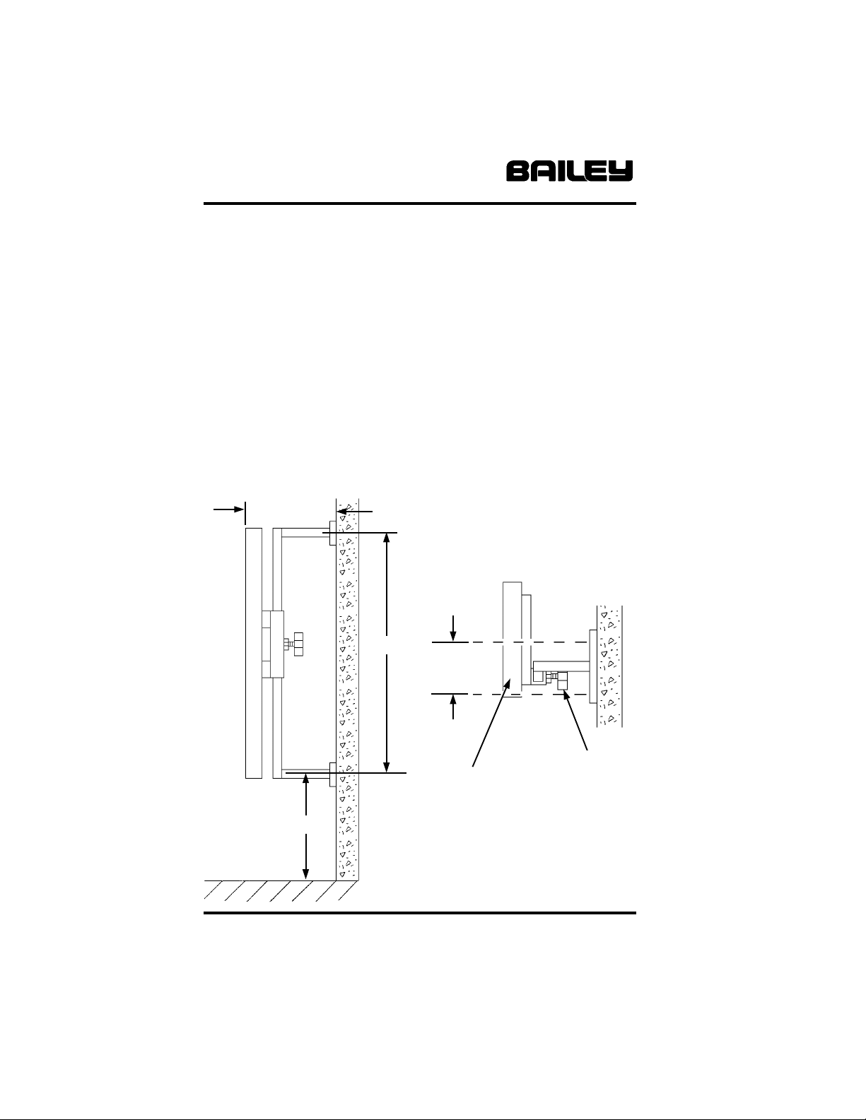
Determine a permanent location for wall mounting, and mark
the wall using the location dimensions in Figure 1, page 8.
[continued on page 8]
BAILEY MANUFACTURING COMPANY
800-321-8372 • FAX: 800-224-5390
Page 8
Page 8 6000 Series Work Simulation Devices
Model 6031 Wall Installation [Cont’d]:
The following minimum materials are required for installation:
• Four (4) each fasteners, 5/16” diameter, for mounting
upper and lower brackets to the wall.
After obtaining proper wall fasteners, install per fastener
manufacturers instructions and mount both brackets to the
wall. Tighten all fasteners securely. Loosen height Adjust
Knob and check adjustment; retighten in desired location.
Check all components for tighness and proper fit. Review
Operation section before placing unit into service.
Figure 1
Model 6031 Work Station Installation
7 1/4”[min.]
Top View
47 3/8”
5”
Work Surface
Board
10” w x 48” h
21
Side View
Height Adjust
BAILEY MANUFACTURING COMPANY
800-321-8372 • FAX: 800-224-5390
#21443
Knob
Page 9
6000 Series Work Simulation Devices Page 9
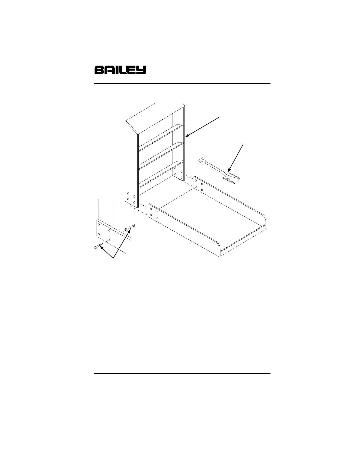
Figure 2
Model 6045 Shoveling Work Station Assembly
Shelf Unit
#16212
Shovel
Base
#2300 3/8 x 2 Carriage Bolt, (8) EA
#3610 3/8 Flatwasher, (8) EA
#3597 3/8 Lockwasher, (8) EA
#2560 3/8 Hex Nut, (8) EA
Model 6045 Assembly:
Locate the Base where the finished unit is to be used. Slide
the upright Shelf into the Base as shown in Figure 2, above,
and align the holes in both parts. Install all eight (8) sets of
fasteners with Hex nuts and Washers on the inside, and
tighten securely.
Check all components for tighness and proper fit. Review
Operation section before placing unit into service.
[continued on page 10]
BAILEY MANUFACTURING COMPANY
800-321-8372 • FAX: 800-224-5390
Page 10
Page 10 6000 Series Work Simulation Devices
Assembly [Cont’d]:
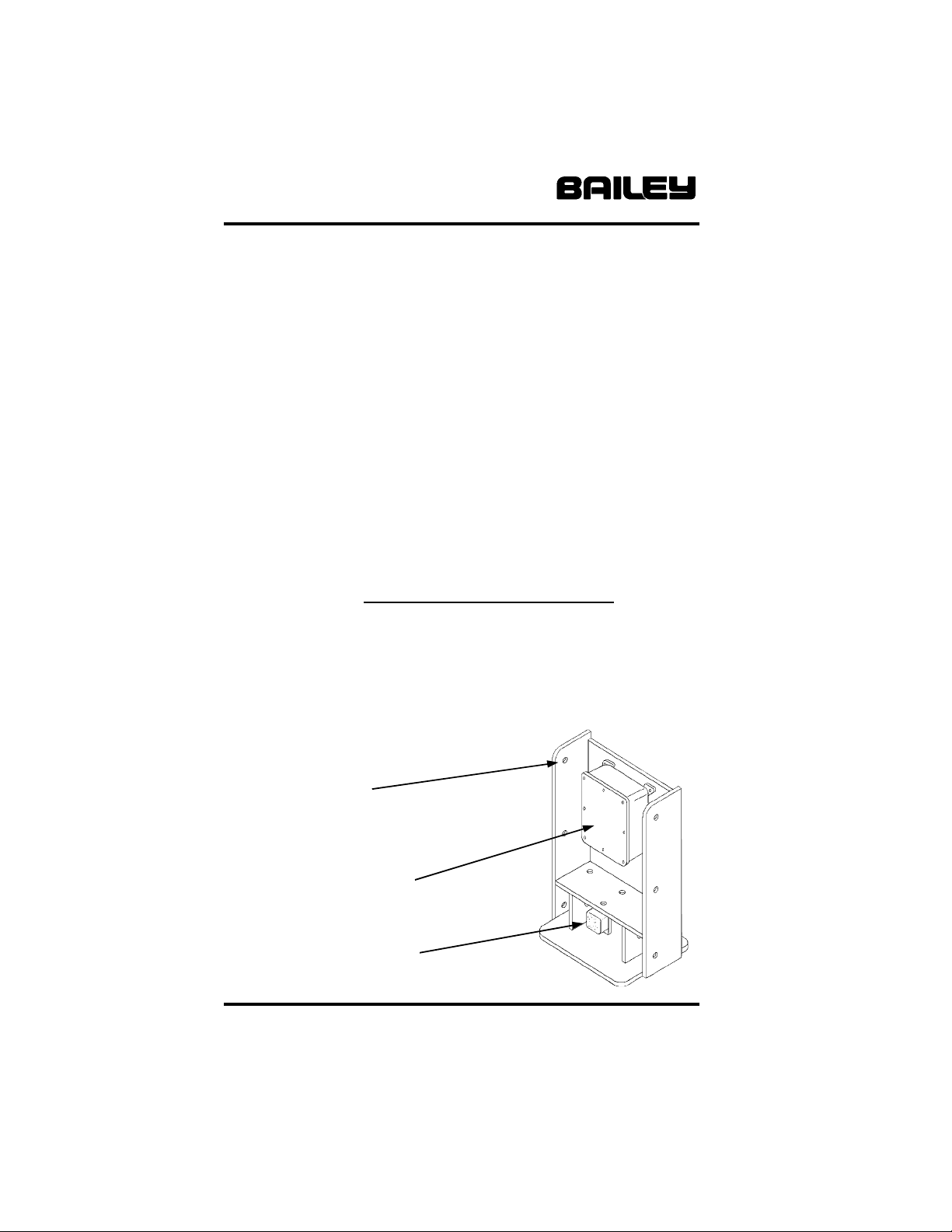
Model 6046 Assembly [Figure 3, below]:
The Tabletop Electrical Assembly Center is preassembled.
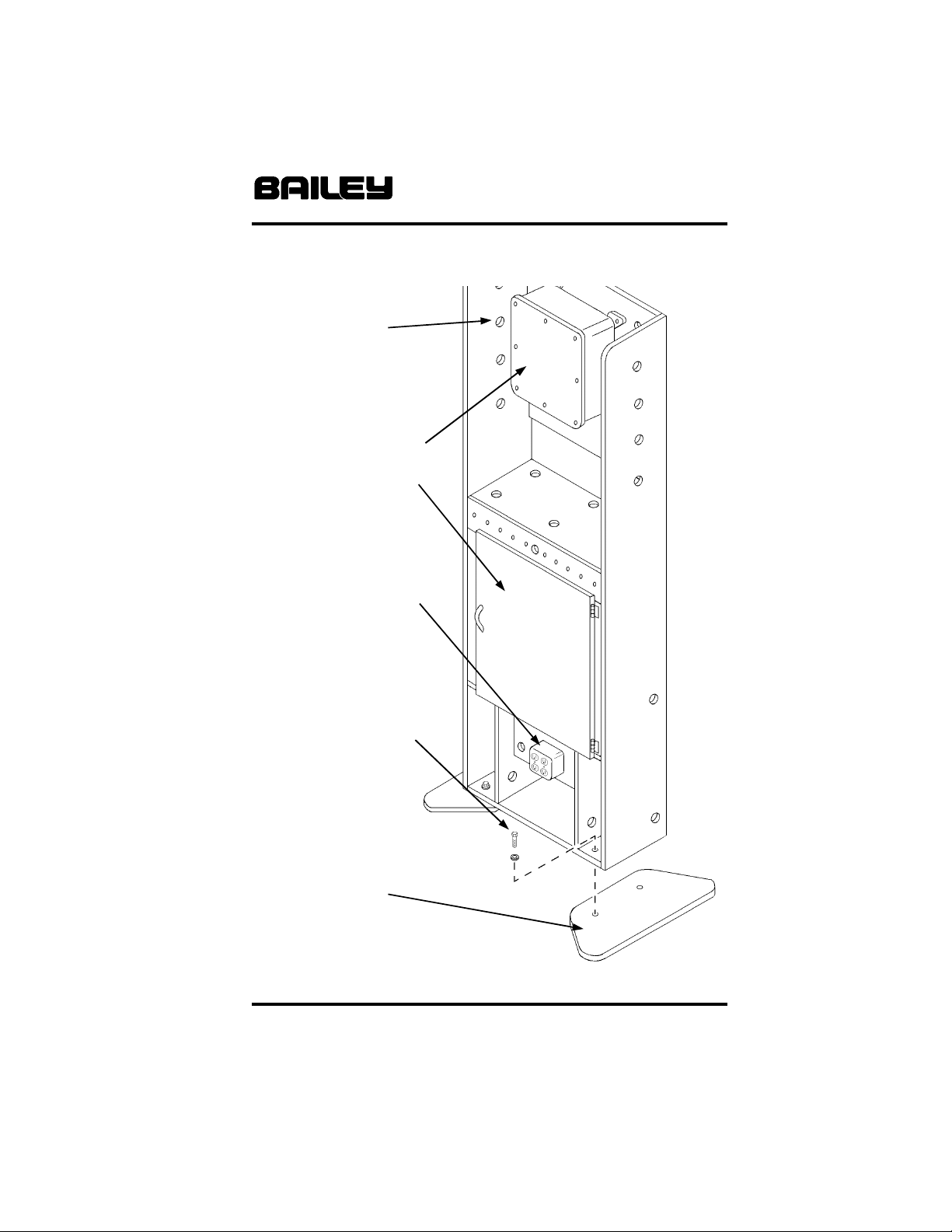
Model 6047 Assembly [Figure 4, opposite page]:
Attach the two (20) Cabinet Supports to the main cabinet,
one on each side as shown in Figure 4, opposite page.
Fasten each support using two (2) Hex head Screws and
Flatwashers, and tighten securely. Reverse Lower Cabinet
Door handle from shipping position [inside] and reinstall.
Check all components for tighness and proper fit. Review
Operation section before placing unit into service.
Warning: These products are intended for work
simulation only.
Do not use with live current!
Figure 3
Model 6046 Tabletop
Electrical Assembly Center [preassembled]
Holes for routing
simulated wiring
(wiring supplies
included)
Simulated Junction Box
(with removable cover)
Simulated electrical
outlet box (see Safety
section before using)
BAILEY MANUFACTURING COMPANY
800-321-8372 • FAX: 800-224-5390
Page 11
6000 Series Work Simulation Devices Page 11
Figure 4
Model 6047 Deluxe Electrical Assembly Center
Holes for routing
simulated wiring
[wiring supplies
included]
Simulated Junction Box
with removable cover
[one inside lower
cabinet, not shown]
Simulated electrical outlet
box (see Safety section
before using)
#1275 1/4 x 1 Hex Head
Screw, (4) EA
#3581 1/4 Flatwasher
(4) EA
Cabinet Support
(2) EA
BAILEY MANUFACTURING COMPANY
800-321-8372 • FAX: 800-224-5390
Page 12

Page 12 6000 Series Work Simulation Devices
Assembly, [Cont’d]:
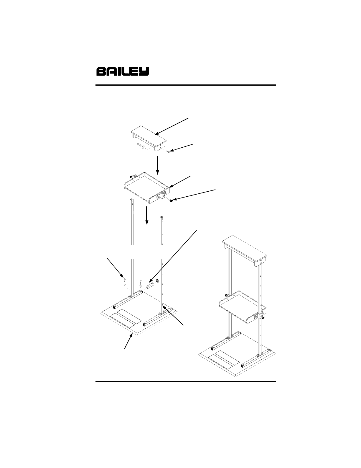
Model 6049 Assembly [Refer to Figure 5, opposite page]:
Place all parts in the location where the unit will be used. The
Base is supplied preassembled, with four (4) 3/8 x 1 1/4” Hex
Head screws and Washers installed in the two (2) Base
Tubes, where the vertical Uprights attach to them.
In order not to “lose” a Tube Insert in a Base Tube by
removing these screws all at once, remove only one (1) set of
screws and washers from each Base Tube at a time. Attach
each Upright to the Base with this screw and washer set first,
then remove the second set, and attach the Upright with
these. Note that the holes in both Uprights must face
outward. Do not tighten these screws completely at this
time. If a Tube Insert becomes “lost” inside the Base Tube,
remove the rear End Cap and the 3/8 Hex Head Screw, and
the Insert will slide out of the Tube.
With both Uprights attached to the Base, place preassembled
Adjustable Shelf over the Uprights until at the lowest
adjustment hole location. Install the two (2) Plunger
Assemblies and fully engage them both in the lowest holes.
Install Top Shelf to the uprights using four (4) 3/8 x 2 1/2” Hex
Head screws, Lockwashers and Hex Nuts as shown.
Tighten lower Upright mounting screws securely. Pull
plungers back and slide Adjustable Shelf up until locked into
the uppermost holes. Tighten the Top Shelf mounting screws
securely. Check Adjustable Shelf operation by engaging and
locking into all Upright hole positions.
Check all components for tighness and proper fit. Review
Operation section before placing unit into service.
BAILEY MANUFACTURING COMPANY
800-321-8372 • FAX: 800-224-5390
Page 13
6000 Series Work Simulation Devices Page 13
Figure 5
Model 6049 Adjustable Shelf
Top Shelf
#1420 3/8 x 2 1/2” Hex Screw (4)
EA
#3597 3/8 Lockwasher, (4) EA
#3610 3/8 Flatwasher, (4) EA
Pre-assembled Adjustable Shelf
#15031
Plunger Assembly, (2)
#1415 3/8 x 2” Hex Screw, (4) EA
#3597 3/8 Lockwasher, (4) EA
Tube Insert, (2) EA
End Cap, (4) EA
#1405 3/8 x 1 1/4” Hex Screw (4) EA
#3597 3/8 Lockwasher, (4) EA
Pre-assembled Base
& Base Tubes
BAILEY MANUFACTURING COMPANY
800-321-8372 • FAX: 800-224-5390
Upright
(2) EA
Assembled Unit
Page 14

Page 14 6000 Series Work Simulation Devices
Operation:
Model 6030 Lift Box/Bolt Center:
Caution: Each facility must use its own definition of a safe lift.
Identify the patients body mechanics with preliminary tests
using empty Lift Boxes. In all cases, the back should be
stable, with the legs and arms used for power. Always
consider ergonomic factors when designing work simulation
tasks.
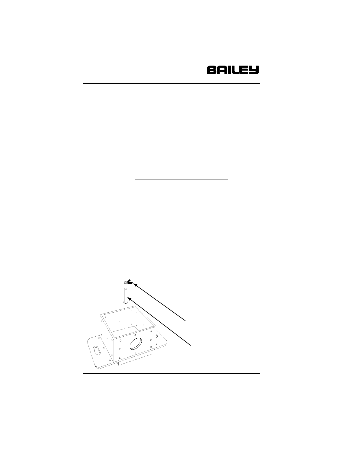
The Disk Weight Holder [Figure 7, page 16] may be removed
by unscrewing by hand; the Weight Keeper is removed by
squeezing the Tabs together and lifting off of the Holder. Use
the supplied hardware kit to simulate hand dexterity tasks.
Model 6031 Work Station [Refer to Figure 1, page 8]:
Adjust the working height of the unit by loosening the Height
Adjust Knob, behind the work surface. Retighten the Knob
when in the desired location. Do not overtighten! Use the
supplied hardware kit to simulate standing assembly tasks.
Model 6044 Hand Assembly Device:
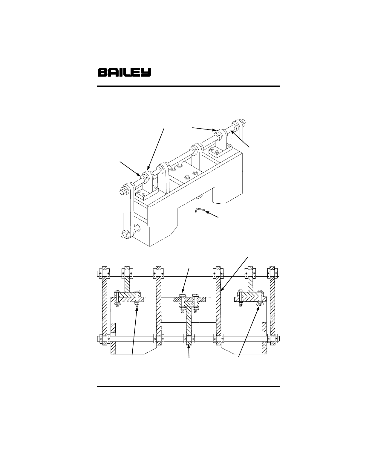
This preassembled unit provides a challenging task routine
for advanced assembly techniques. Refer to the diagrams in
Figure 6, opposite page, if reassembly proves difficult. The
5/32” Hex Key required for removing and installing the Shaft
Collars is supplied with the unit.
Model 6045 Shoveling Station:
The Shoveling Station [Figure 2, page 9] is designed for use
with any type of sand or other small granular material [not
included]. A Shovel is supplied with the unit.
The Station has three shelves at entry heights of 15”, 30”
and 43”. These shelves are angled toward the back in order
to allow the shoveled material to return to the Base with a
minimum of loss.
[continued on page 16]
BAILEY MANUFACTURING COMPANY
800-321-8372 • FAX: 800-224-5390
Page 15
6000 Series Work Simulation Devices Page 15
Figure 6
Model 6044
Hand Assembly Device [preassembled]
Fully Assembled
View
#15151
Shaft Collar
(22) EA
Fully Assembled
Cutaway View
Top
Bracket
(2) EA
3/8 Hex Head
Screw, Washer,
Hex Nut
(4) EA
7/8” Shaft
(2) EA
Main
Housing
(1) EA
5/32 Hex Key
[supplied] for Shaft
Collar removal
and installation
Shaft
Bracket
(4) EA
1/4” Hex Head
Screw, Washer,
Hex Nut
(4) EA
Bottom
Bracket
(1) EA
1/4” Round Head
Screw, Washer,
BAILEY MANUFACTURING COMPANY
800-321-8372 • FAX: 800-224-5390
Wing Nut
(4) EA
Page 16
Page 16 6000 Series Work Simulation Devices
Operation [Cont’d]:
Models 6046 & 6047 Electrical Assembly Centers:
Electrical Assembly Centers feature actual industry standard
parts and supplies for use in simulated work tasks. The
Junction boxes have removable covers and internal terminal
strips; the cabinets feature pass-through holes for wiring runs
[Refer to Figures 3 & 4, pages 10 & 11]. Industrial trade tools
are not supplied and may be required for some realistic work
simulations.
Warning: These products are intended for work
simulation only.
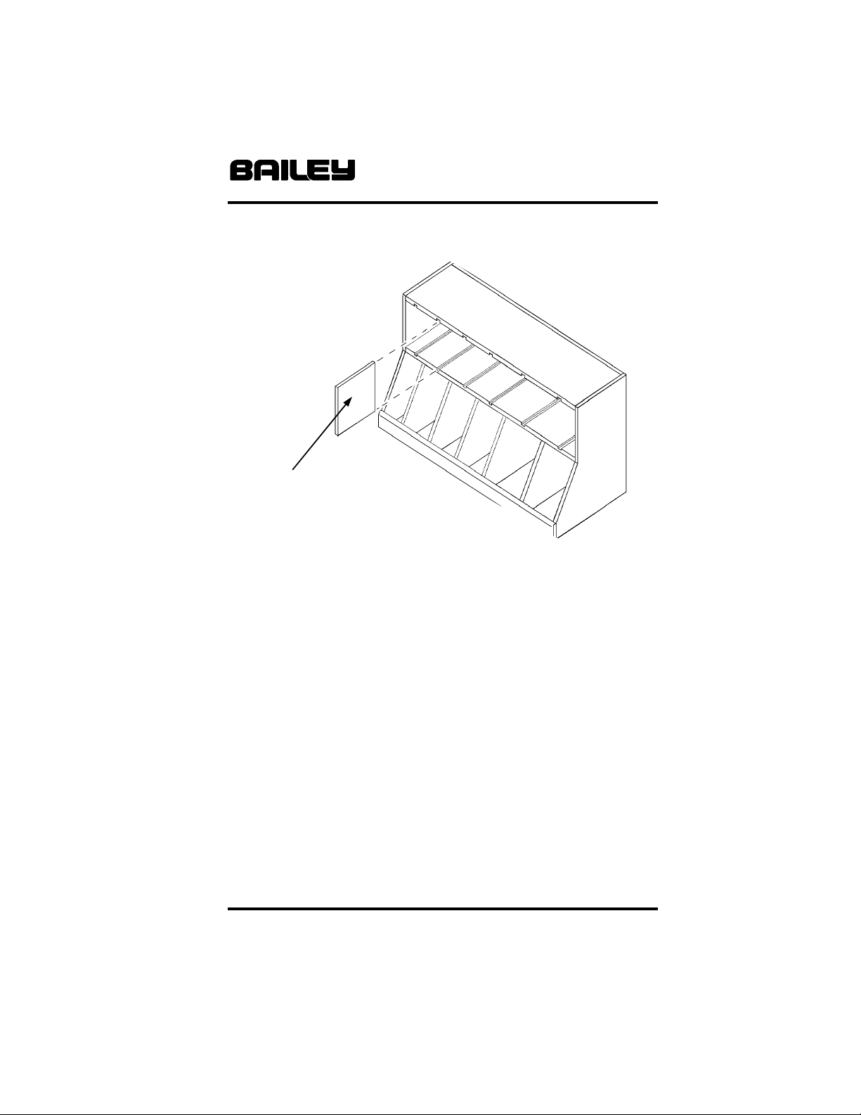
Model 6048 Sorting Bin:
This Sorting Bin features six fixed lower bins and five variable
upper bins. The four (4) Sort Bin Dividers may be inserted
into the upper bin grooves in any arrangement [see Figure 8,
opposite page].
Model 6049 Adjustable Height Shelf Unit [Figure 5, page 13]:
The Adjustable Shelf has eight (8) fixed locations. Ensure
Plungers are fully engaged before usig the Shelf! When
adjusting shelf height, both Plungers must be retracted at the
same time before raising or lowering.
Do not use with live current!
Figure 7
Model 6030
Lifting/Bolt Center
[preassembled]
Weight Keeper
Disk Weight
Holder
BAILEY MANUFACTURING COMPANY
800-321-8372 • FAX: 800-224-5390
Page 17
6000 Series Work Simulation Devices Page 17
Figure 8
Model 6048 Sorting Bin
[preassembled]
Sort Bin Divider
(4) EA
Model 6049 Adjustable Height Shelf Unit [Cont’d]:
For the easiest adjustment, approach the Shelf from behind,
or use two people. Note: Due to the vertical, space-saving
design of this unit, some movement in the Uprights will be
noticeable while in use. The unit is stable as long as the
combined load on both shelves does not exceed the load
rating on Page 4. Avoid placing the entire load on the top
shelf.
Safety:
Be safe! All Bailey Work Simulation Devices are designed to
allow the therapist to create protocols based upon a patients
previous work experience rehabilitation goals. Always design
work simulation tasks within NIOSH and OSHA guidelines,
and observe product Load Ratings as stated on page 4
where applicable.
BAILEY MANUFACTURING COMPANY
800-321-8372 • FAX: 800-224-5390
Page 18

Page 18 6000 Series Work Simulation Devices
Maintenance & Cleaning:
Regularly inspect components for wear and proper
adjustment. Should the unit need attention, remove from
service until the unit is returned to its original condition. A
convenient Inspection and Service Logsheet is provided on
page 23 for recordkeeping.
To help keep your product in good condition, clean as
required using abrasive free and solvent free products. Test
any cleaner or disinfectant on a small, inconspicuous location
before using. Discontinue use if surface softens, discolors, or
loses gloss.
Never use any cleaners or disinfectants containing harsh
solvents on product surfaces. Check their Material Safety
Data Sheet and consult the manufacturer with any questions.
Some chemicals will severely shorten the life of your plastic
parts and lacquer coated wood finishes.
For light soiling, we recommend liquid dish soap and water,
or liquid cleanser and water applied sparingly with a soft
bristle brush. For difficult stains or disinfection, use a solution
of 10% household bleach [sodium hypochlorite] and 90%
water applied sparingly with a soft white cloth. Rinse with
water dampened cloth to remove any remaining soap,
cleanser or bleach solution.
Troubleshooting:
Your new Bailey Work Simulation Device will provide years of
reliable service. In the event the Table does not function
correctly, inspect all components for tightness and proper
condition.
For detailed information or component replacement, contact
Bailey Customer Service at the number on this page. Have
your date of purchase and Bailey Dealer information
handy for faster service.
BAILEY MANUFACTURING COMPANY
800-321-8372 • FAX: 800-224-5390
Page 19

6000 Series Work Simulation Devices Page 19
Five Year Limited Warranty:
Bailey Manufacturing Company warrants the products we
manufacture to be free of defects in materials, workmanship,
or design under normal use and service conditions for five
years after the date of original purchase (two years for Bailey
Basics). Resale products and components manufactured by
others will carry the warranty of the manufacturer. If the
product and/or equipment should become defective within the
designated warranty period, Bailey Manufacturing Company
will repair or replace it (at our option) free of charge, including
return transportation to you, provided you deliver the
equipment or product prepaid to Bailey Manufacturing
Company at 118 Lee Street, Lodi, Ohio 44254. Please
receive “authorization” before returning product to the factory,
as Bailey Manufacturing Company will not accept collect
shipments. Bailey Manufacturing Company reserves the right
to repair or replace component parts without return of the
entire unit.
This warranty does not include damage resulting from
accident, abuse, or misuse of the product and expressly
excludes normal wearing of parts or defect caused by
transportation, accident, fire, flood, alteration, or negligence.
Bailey’s warranty liability is limited to that stated above; other
than the warranty stated above, there are no warranties
expressed or implied. Bailey will have no responsibility for
consequential or incidental damages.
BAILEY MANUFACTURING COMPANY
800-321-8372 • FAX: 800-224-5390
Page 20

Page 20 6000 Series Work Simulation Devices
Product Support:
Bailey Manufacturing Company is totally committed to
producing the finest quality physical, occupational, and sports
medicine products. Our goal is your total satisfaction. If you
experience any problems, please feel free to contact a Bailey
Customer Service Representative at 1-800-321-8372
between the hours of 8:30 AM and 4:30 PM Eastern Time
weekdays.
The following information is provided to help ensure that your
experience with Bailey is a positive one. Please read this
information carefully before you unpack or begin assembly.
If You Need Assistance:
To provide the best possible service to our customers and
dealers, warranty claims should be made directly to Bailey.
Since Bailey is in the best position to solve the customer’s
problem, it will speed up the process and help ensure total
customer satisfaction. Should you encounter any problem
with our products or services, please contact a Bailey
Customer Service Representative at 1-800-321-8372
between the hours of 8:30 AM and 4:30 PM Eastern Time,
weekdays. Please have the date of purchase and Bailey
dealer information recorded inside the front cover of this
manual, or a copy of your packing list available to help our
customer service representative provide you with the fastest
service. In most cases, you will also want to notify your dealer
to enable them to provide any further assistance.
BAILEY MANUFACTURING COMPANY
800-321-8372 • FAX: 800-224-5390
Page 21

6000 Series Work Simulation Devices Page 21
Registration:
Product registration will be accomplished through the use of
the enclosed Product Registration Form. Please take time to
complete this Form and return it to Bailey. We also ask that
you answer a few simple questions concerning our products
and services. Our goal is your total satisfaction, and this
information will be used to improve our products and services
for you...the customer. Please take a moment to record your
purchase inside the front cover of this manual. Note the date
and the name of your Bailey dealer.
Damage or Loss in Transit:
All of our equipment is thoroughly inspected and carefully
packed before leaving our plant. It is receipted for by the
carrier as having been shipped in good condition. Any loss or
damage which occurs to the equipment in route will be solely
through negligence of the carrier and all claims must be filed
directly with the carrier. Important; If a shipment is delivered
to you in a visibly damaged condition or in a quantity that is
less than is enumerated on the Bill of Lading or delivery
receipt, insist on a notation of this damage or shortage by the
delivering carrier’s agent on the delivery receipt or freight bill.
When a shipment has been delivered to you in apparent good
condition, but upon opening the containers or crate, damage
is discovered, notify the delivering carrier immediately upon
discovery. This notification must be made within 5 days of
receipt of the shipment. Insist upon an inspection and
inspection report. You must retain all packaging, including the
carton or crate in which the damaged item was shipped, until
inspection has been made. All claims must be made by you,
the consignee, directly to the carrier or its agents.
BAILEY MANUFACTURING COMPANY
800-321-8372 • FAX: 800-224-5390
Page 22

Page 22 6000 Series Work Simulation Devices
Returns:
Merchandise to be returned must have proper authorization.
Please contact your dealer for assistance with this procedure.
A reference (return authorization or RA) number is to be
clearly marked on all cartons and correspondence. Freight
charges are to be prepaid, as collect shipments are not
accepted. Items must be in the original packaging and
returned within 30 days of the invoice date. Returns that are
not the result of a warranty claim are subject to a restocking
fee of 20% to cover inspection and handling. Any damage
due to use, mishandling, or improper packing of the return will
be noted and deducted from the credit issued. Special order
items may not be returned for credit. Bailey Customer Service
Representatives will complete a “Returned Merchandise
Information” form to clearly identify all information concerning
the returned merchandise.
Specifications:
Due to continuous improvements in design, materials, and
construction techniques, specifications in the Bailey catalog
are subject to change without notice. In all cases, the
equipment shipped will be of equal or superior quality. Bailey
Manufacturing Company also reserves the right to
discontinue the manufacture of any product at such time as
we consider necessary.
Customer Service:
When service is required, it is nearly impossible to place a
value on it. For that reason we have an extremely competent
Customer Service Department available to assist you with
answers to your questions or recommendations in your
planning process. In the unlikely event that a product may be
in need of repair, our staff will assist with prompt identification
of the required replacement part. Have the date of purchase
and the name of your Bailey dealer handy for reference.
Please contact us at 1-800-321-8372 between the hours of
8:30 AM and 4:30 PM Eastern Time weekdays for
assistance.
BAILEY MANUFACTURING COMPANY
800-321-8372 • FAX: 800-224-5390
Page 23
6000 Series Work Simulation Devices Page 23
Inspection & Service Logsheet
DATE BY DESCRIPTION
BAILEY MANUFACTURING COMPANY
800-321-8372 • FAX: 800-224-5390
Page 24

BAILEY MANUFACTURING COMPANY
800-321-8372 • FAX: 800-224-5390
Mail: P.O. Box 130, Lodi, OH 44254-0130
Shipments: 118 Lee St., Lodi, OH 44254
 Loading...